EP3260286B1 - Fülleinrichtung für eine rundläuferpresse - Google Patents
Fülleinrichtung für eine rundläuferpresse Download PDFInfo
- Publication number
- EP3260286B1 EP3260286B1 EP17170118.8A EP17170118A EP3260286B1 EP 3260286 B1 EP3260286 B1 EP 3260286B1 EP 17170118 A EP17170118 A EP 17170118A EP 3260286 B1 EP3260286 B1 EP 3260286B1
- Authority
- EP
- European Patent Office
- Prior art keywords
- filling
- stirrer
- stirrer blade
- blade wheel
- cavities
- Prior art date
- Legal status (The legal status is an assumption and is not a legal conclusion. Google has not performed a legal analysis and makes no representation as to the accuracy of the status listed.)
- Active
Links
Images
Classifications
-
- B—PERFORMING OPERATIONS; TRANSPORTING
- B30—PRESSES
- B30B—PRESSES IN GENERAL
- B30B15/00—Details of, or accessories for, presses; Auxiliary measures in connection with pressing
- B30B15/30—Feeding material to presses
- B30B15/302—Feeding material in particulate or plastic state to moulding presses
- B30B15/308—Feeding material in particulate or plastic state to moulding presses in a continuous manner, e.g. for roller presses, screw extrusion presses
-
- B—PERFORMING OPERATIONS; TRANSPORTING
- B30—PRESSES
- B30B—PRESSES IN GENERAL
- B30B11/00—Presses specially adapted for forming shaped articles from material in particulate or plastic state, e.g. briquetting presses, tabletting presses
- B30B11/02—Presses specially adapted for forming shaped articles from material in particulate or plastic state, e.g. briquetting presses, tabletting presses using a ram exerting pressure on the material in a moulding space
- B30B11/08—Presses specially adapted for forming shaped articles from material in particulate or plastic state, e.g. briquetting presses, tabletting presses using a ram exerting pressure on the material in a moulding space co-operating with moulds carried by a turntable
-
- B—PERFORMING OPERATIONS; TRANSPORTING
- B01—PHYSICAL OR CHEMICAL PROCESSES OR APPARATUS IN GENERAL
- B01F—MIXING, e.g. DISSOLVING, EMULSIFYING OR DISPERSING
- B01F27/00—Mixers with rotary stirring devices in fixed receptacles; Kneaders
- B01F27/05—Stirrers
- B01F27/11—Stirrers characterised by the configuration of the stirrers
- B01F27/112—Stirrers characterised by the configuration of the stirrers with arms, paddles, vanes or blades
- B01F27/1125—Stirrers characterised by the configuration of the stirrers with arms, paddles, vanes or blades with vanes or blades extending parallel or oblique to the stirrer axis
-
- B—PERFORMING OPERATIONS; TRANSPORTING
- B01—PHYSICAL OR CHEMICAL PROCESSES OR APPARATUS IN GENERAL
- B01F—MIXING, e.g. DISSOLVING, EMULSIFYING OR DISPERSING
- B01F27/00—Mixers with rotary stirring devices in fixed receptacles; Kneaders
- B01F27/05—Stirrers
- B01F27/11—Stirrers characterised by the configuration of the stirrers
- B01F27/19—Stirrers with two or more mixing elements mounted in sequence on the same axis
- B01F27/192—Stirrers with two or more mixing elements mounted in sequence on the same axis with dissimilar elements
-
- B—PERFORMING OPERATIONS; TRANSPORTING
- B01—PHYSICAL OR CHEMICAL PROCESSES OR APPARATUS IN GENERAL
- B01F—MIXING, e.g. DISSOLVING, EMULSIFYING OR DISPERSING
- B01F27/00—Mixers with rotary stirring devices in fixed receptacles; Kneaders
- B01F27/80—Mixers with rotary stirring devices in fixed receptacles; Kneaders with stirrers rotating about a substantially vertical axis
- B01F27/84—Mixers with rotary stirring devices in fixed receptacles; Kneaders with stirrers rotating about a substantially vertical axis with two or more stirrers rotating at different speeds or in opposite directions about the same axis
-
- B—PERFORMING OPERATIONS; TRANSPORTING
- B30—PRESSES
- B30B—PRESSES IN GENERAL
- B30B11/00—Presses specially adapted for forming shaped articles from material in particulate or plastic state, e.g. briquetting presses, tabletting presses
- B30B11/003—Presses specially adapted for forming shaped articles from material in particulate or plastic state, e.g. briquetting presses, tabletting presses using a roller with radially arranged vanes dividing the pressing space in separate chambers
-
- B—PERFORMING OPERATIONS; TRANSPORTING
- B30—PRESSES
- B30B—PRESSES IN GENERAL
- B30B15/00—Details of, or accessories for, presses; Auxiliary measures in connection with pressing
- B30B15/30—Feeding material to presses
- B30B15/302—Feeding material in particulate or plastic state to moulding presses
-
- B—PERFORMING OPERATIONS; TRANSPORTING
- B30—PRESSES
- B30B—PRESSES IN GENERAL
- B30B15/00—Details of, or accessories for, presses; Auxiliary measures in connection with pressing
- B30B15/30—Feeding material to presses
- B30B15/302—Feeding material in particulate or plastic state to moulding presses
- B30B15/304—Feeding material in particulate or plastic state to moulding presses by using feed frames or shoes with relative movement with regard to the mould or moulds
-
- B—PERFORMING OPERATIONS; TRANSPORTING
- B01—PHYSICAL OR CHEMICAL PROCESSES OR APPARATUS IN GENERAL
- B01F—MIXING, e.g. DISSOLVING, EMULSIFYING OR DISPERSING
- B01F2101/00—Mixing characterised by the nature of the mixed materials or by the application field
- B01F2101/22—Mixing of ingredients for pharmaceutical or medical compositions
-
- B—PERFORMING OPERATIONS; TRANSPORTING
- B29—WORKING OF PLASTICS; WORKING OF SUBSTANCES IN A PLASTIC STATE IN GENERAL
- B29C—SHAPING OR JOINING OF PLASTICS; SHAPING OF MATERIAL IN A PLASTIC STATE, NOT OTHERWISE PROVIDED FOR; AFTER-TREATMENT OF THE SHAPED PRODUCTS, e.g. REPAIRING
- B29C31/00—Handling, e.g. feeding of the material to be shaped, storage of plastics material before moulding; Automation, i.e. automated handling lines in plastics processing plants, e.g. using manipulators or robots
- B29C31/04—Feeding of the material to be moulded, e.g. into a mould cavity
- B29C31/042—Feeding of the material to be moulded, e.g. into a mould cavity using dispensing heads, e.g. extruders, placed over or apart from the moulds
- B29C31/047—Feeding of the material to be moulded, e.g. into a mould cavity using dispensing heads, e.g. extruders, placed over or apart from the moulds combined with moving moulds
Definitions
- the invention relates to a filling device for filling cavities of a rotary press, comprising a filling material reservoir and a filling chamber connected to the filling material reservoir with a filling opening, from which filling material can enter the cavities of the rotary press.
- the cavities of a rotary press are filled, metered and/or pre-compressed by means of a filling device with the molding compound to be pressed by the ram of the rotary press.
- the upper and lower punches of the rotary press work together in the cavities for pressing compacts.
- the quality of the pellets produced depends significantly on the quality of the cavity filling. Quality features of the pellets produced are, for example, weight, breaking strength, density distribution and proportion of active ingredients. A reproducible quality of the pellets is an important quality feature according to the pharmacopoeia and requires a reproducible quality of the cavity filling.
- the quality of the cavity filling can be understood, for example, as the fluctuation range of the filling quantities and/or the density distribution of the molding compound within a single cavity and/or the integrity of the molding compound. For example, a uniform weight of all compacts produced can be ensured by a small range of fluctuation in the filling quantities.
- the filling devices must ensure that the quality of the cavity filling is given even with the high performance of today's rotary presses.
- Known filling devices are based on different concepts, such as chamber filling shoes, single or multi-chamber filling systems.
- Agitator impellers are often driven in rotation in the filling chambers of the filling devices.
- Agitator impellers are used in particular in high-performance rotary presses.
- agitator impellers with different numbers and different forms of impellers known.
- the agitator blades constantly transport the molding compound to the cavities, so that the availability of sufficient molding compound to fill the cavities is ensured even at high speeds of the rotary press.
- agitator blades loosen up the molding compound, which has a positive effect on flowability. As a result, a constant quality of cavity filling can be guaranteed even with high tableting performance.
- the effect of the agitator blades of the agitator wheels on the quality of the cavity filling depends, among other things, on the molding compound to be pressed.
- the agitator blades can have a significant effect on the transport quantity of the molding compound and/or on the degree of prevention of bridging and/or loosening.
- disadvantageous effects such as segregation or heating of the molding compound can be prevented.
- a specific agitator blade configuration can ensure good transport of the molding compound to the cavities. However, it does not offer any satisfactory loosening of the molding compound at all times.
- an impeller configuration that ensures good loosening of the molding compound for example, may not ensure satisfactory transport of the molding compound to the cavities. In this respect, there is a conflict of objectives in practice.
- the invention is therefore based on the object of providing a filling device of the type mentioned at the outset, which also satisfactorily fulfills different requirements with regard to cavity filling.
- the invention solves the problem in that a first rotatingly driven agitator wheel with agitator blades and a second rotatingly driven agitator wheel with agitator blades are arranged in the filling chamber, the first and second agitator wheel having different geometry and/or direction of rotation and/or their rotational speed differ.
- the filling device according to the invention is intended for use in a rotary press, in particular a rotary tablet press.
- the rotary press can also be a multiple rotary press, in particular a double rotary press. Several, in particular two, filling devices, pressing stations, ejector stations, etc. are then provided. This is known per se.
- the rotor of such a rotary press has a rotary drive, which drives the rotor, in particular the die plate with the upper and lower punches, to rotate at the rotor speed, for example via a drive shaft.
- the die table can be designed in one piece or be made up of die segments.
- the cavities can be formed by bores made directly in the die table or by detachable matrices inserted in receptacles of the die table.
- the cavities of the die table are filled with a filling material, for example in powder form.
- the filling material is then pressed in a known manner by the upper and lower punches of the rotary press in the cavities to form a compact, in particular a tablet.
- the compacts are ejected from the rotary press in an ejector station.
- the The ejector station can, for example, comprise a stripper which is arranged directly above the die plate and which strips the ejected pellets from the die plate rotating under the stripper in the direction of a discharge channel.
- the filling device comprises a filling material reservoir, which can be connected to the filling chamber via a feed section, for example.
- the filling material reaches the filling chamber from the filling material reservoir, for example via the feed section, in particular due to the force of gravity.
- the filling material reservoir can be funnel-shaped.
- the filling chamber When mounted in the rotary press, the filling chamber is located directly above the die plate, so that during operation filling material falls out of the filling chamber through the filling opening, in particular due to the force of gravity, into the cavities of the die plate rotating under the filling chamber.
- the filling chamber can be a so-called filling shoe.
- At least two rotationally driven impellers are arranged in the filling chamber of the filling device.
- the impellers each have impellers.
- the filling device has one or more rotary drives which drive the agitator impellers in rotation.
- the agitator blades of the impeller wheels are distributed over the circumference of the impeller wheel and rotate in the filling chamber filled with the filling material.
- the first and second agitator impellers differ in terms of their geometry and/or their direction of rotation and/or their rotational speed.
- the geometry of the agitator blades of the first and second agitator blades can differ.
- the agitator blades can have different cross sections.
- the agitator blades of one impeller can be thicker than the agitator blades of the other impeller.
- the direction of rotation or the speed of rotation and in particular the geometry of the agitator blades influence the availability and Flowability of the filling material in different dimensions.
- the selection of the impeller configuration to be used depends on the nature of the filling material to be compressed.
- the provision according to the invention of at least two agitator impellers of different configurations in a filling chamber allows the advantages of different agitator impeller configurations, in particular agitator blade geometries, to be combined with one another. In this way it is possible to resolve the conflict of objectives that exists in the prior art when only one agitator impeller is used in a filling chamber. In this way, even at very high speeds of the rotor of the rotary press and correspondingly very high pressing capacities, a reliably constant quality of the cavity filling and thus of the compacts can be achieved.
- the first impeller and the second impeller are arranged one above the other in the filling chamber. Furthermore, in the variant in which the agitator impellers differ in terms of their geometry, the first agitator impeller and the second agitator impeller are driven in rotation via concentric rotary axes. In this case, one of the agitator impellers is driven in rotation via a hollow axle, in which the axis of rotation of the other agitator impeller is arranged so that it can rotate independently.
- the agitating blades of one of the first and second impellers may be formed of a flat bar, and the agitating blades of the other of the first and second impellers may be formed of a round bar.
- the agitator blade with the agitator blades formed from a round rod can be arranged in the filling chamber above the agitator blade wheel with the agitator blades formed from a flat rod.
- the above-described combination of the effects of the agitator blades is used particularly advantageously.
- the agitator blades of the first and/or second impeller wheel can each lie in a preferably horizontal plane. In particular, they lie in a cross-section through the agitator impeller in a preferably horizontal plane.
- the agitator blades of an impeller can each be connected at the same height to the axis of rotation of the impeller and in this configuration have no changes in direction over their length, such as bends or offsets, particularly in the direction of the axis of rotation.
- the agitator blades of the first and/or second impeller wheel do not lie in a preferably horizontal plane, in particular in the cross section through the impeller wheel.
- the agitator blades can be connected to the axis of rotation of the agitator blade wheel at the same level. However, they then have one or more changes in direction over their length, such as curvatures or offsets, etc., in particular in the direction of the axis of rotation.
- a combination of the aforementioned configurations is also possible, ie that the agitator blades are one of the first and second Impeller lie in such a plane and the impellers of the other of the first and second impeller are not in such a plane.
- the agitator impeller whose agitator blades do not lie in one plane can be arranged above the agitator impeller whose agitator blades lie in one plane.
- At least one third rotating impeller is arranged in the filling chamber, with the at least one third impeller differing from the first and/or second impeller in terms of its geometry and/or its direction of rotation and/or its speed of rotation .
- this agitator impeller the same configurations can be present as explained above for the first and/or second agitator impeller.
- At least one further filling chamber of the filling device can be provided above or to the side of the (first) filling chamber.
- At least one further agitator impeller driven in rotation can be arranged in the at least one further filling chamber.
- a control device can be provided which controls the speed and/or the direction of rotation of the first and second agitator impellers. This can be the machine control of the rotary press, for example. Of course, the control device can also control other agitator impellers that are provided, if appropriate.
- the invention also relates to a rotary press comprising a rotor which can be rotated by means of a rotary drive, the rotor having an upper punch guide for the upper press punch of the rotary press and a lower punch guide for the lower press punch of the rotary press and one between the punch guides arranged die plate, wherein the pressing rams interact with cavities of the die plate, further comprising a filling device according to the invention, through which filling material to be pressed is filled into the cavities of the die plate, further comprising at least one upper pressure device and at least one lower pressure device, which in operation with the upper Press rams and interact with the lower press rams for pressing the filling material in the cavities of the die table, and comprising an ejection device in which compacts produced in the cavities are ejected from the rotary press.
- the rotary press can be designed as basically explained above.
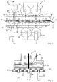
- the rotary press shown in the figures in particular a rotary tablet press, comprises a rotor which is driven in rotation by a rotary drive (not shown in detail) and has a die plate 10 which has a plurality of cavities 12 .
- the cavities 12 can be formed, for example, by bores in the die table 10 .
- the rotor further comprises a plurality of upper punches 14 and lower punches 16 which are synchronous with the die table 10 run around Each pair of upper punch 14 and lower punch 16 is associated with a bore 12 .
- the axial movement of the punches 14 and 16 as the rotor rotates is controlled by upper cams 18 and lower cams 20 .
- the rotary press also includes a filling device 22 which has a filling chamber 24 .
- the filling device 22 also includes a funnel-shaped filling material reservoir 29 which is connected to the filling chamber 24 via a feed section 31 .
- powdered filling material flows from the filling material reservoir 29 via the feed section 31 into the filling chamber 24 due to the force of gravity, and from there via a filling opening provided on the underside of the filling chamber 24 again due to the force of gravity into the cavities 12 of the die table 10.
- the rotary press also includes a pressing station 30.
- the pressing station 30 has a pre-pressing device with an upper pre-compression roller 32 and a lower pre-compression roller 34 and a main pressing device with an upper main pressure roller 36 and a lower main pressure roller 38.
- the rotary press also includes an ejector station 40, in this case with a Stripper 42, which feeds the pellets 44 produced in the rotary press, in particular tablets, to a pellet outlet 46 for further processing.
- a control device for operating the rotary press is shown at reference number 48 .
- the control device 48 is connected, inter alia, to the rotary drive of the rotor and the rotary drive of the impeller wheels 26, 28 of the filling device 22 via lines that are not shown in detail.
- the first agitator blade wheel 26 has a plurality of agitator blades 50 which are connected to an axis of rotation 54 at the same height.
- the impeller wheel 28 also has a plurality of impellers 52 which are also connected to the axis of rotation 54 at the same height.
- the agitator blades 52 of the second impeller wheel 28 are located in the in 2 example shown in a horizontal plane. In particular, they have no changes in direction in the direction of the axis of rotation 54.
- the agitator blades 52 of the second impeller wheel 28 are formed from a flat bar.
- the agitator blades 50 of the first impeller wheel 26, on the other hand do not lie in a horizontal plane, but are each cranked.
- the stirring blades 50 of the first stirring impeller 26 are formed of a round bar.
- the rotor is driven in rotation at a rotor speed set by the control device 48 .
- the agitator impellers 26, 28 are driven to rotate at a speed controlled by the control device 48.
- the cavities 12 pass under the filling opening of the filling chamber 24 .
- the filling material to be pressed is filled into the cavities 12 via the filling opening, as explained.
- the fill level is predetermined by the lower punches 16 that are partially moved into the cavities 12 .
- the filling material in the cavities 12 is pressed by the upper punch 14 and lower punch 16, namely successively by the pre-compression rollers 32, 34 and the main pressure rollers 36, 38.
- the upper punches can be removed from the cavities 12 retracted and the compacts 44 produced are ejected from the lower punches 16 onto the upper side of the die table 10, so that they are scraped by the stripper 42 from the upper side of the die table 10 and the compacts outlet 46 is fed for further processing.
- the combination of two differently designed impellers 26, 28 shown in the embodiment shown in the figures ensures optimal loosening of the filling material in the filling chamber 24 on the one hand and optimal transport of the filling material into the cavities 12 on the other.
Landscapes
- Engineering & Computer Science (AREA)
- Mechanical Engineering (AREA)
- Chemical & Material Sciences (AREA)
- Chemical Kinetics & Catalysis (AREA)
- Basic Packing Technique (AREA)
- Processing And Handling Of Plastics And Other Materials For Molding In General (AREA)
Description
- Die Erfindung betrifft eine Fülleinrichtung zum Befüllen von Kavitäten einer Rundläuferpresse, umfassend ein Füllmaterialreservoir und eine mit dem Füllmaterialreservoir in Verbindung stehende Füllkammer mit einer Befüllöffnung, aus der Füllmaterial in die Kavitäten der Rundläuferpresse gelangen kann.
- Die Kavitäten einer Rundläuferpresse werden mittels einer Fülleinrichtung mit der durch die Stempel der Rundläuferpresse zu verpressenden Pressmasse befüllt, dosiert und/oder vorverdichtet. Ober- und Unterstempel der Rundläuferpresse wirken in den Kavitäten zum Pressen von Presslingen zusammen. Die Qualität der hergestellten Presslinge hängt signifikant von der Qualität der Kavitätenbefüllung ab. Qualitätsmerkmale der hergestellten Presslinge sind beispielsweise Gewicht, Bruchfestigkeit, Dichteverteilung und Wirkstoffanteil. Eine reproduzierbare Qualität der Presslinge ist ein wichtiges Qualitätsmerkmal nach dem Arzneibuch und setzt eine reproduzierbare Qualität der Kavitätenbefüllung voraus. Als Qualität der Kavitätenbefüllung kann zum Beispiel die Schwankungsbreite der Füllmengen und/oder die Dichteverteilung der Pressmasse innerhalb einer einzelnen Kavität und/oder die Unversehrtheit der Pressmasse verstanden werden. Beispielsweise kann durch eine geringe Schwankungsbreite der Füllmengen ein gleichförmiges Gewicht aller hergestellten Presslinge gewährleistet werden.
- Die Fülleinrichtungen müssen gewährleisten, dass die Qualität der Kavitätenbefüllung auch bei der hohen Leistung heutiger Rundläuferpressen gegeben ist. Bekannte Fülleinrichtungen basieren auf unterschiedlichen Konzepten, wie zum Beispiel Kammerfüllschuhen, Ein- oder Mehrkammer-Füllsystemen. Häufig werden in den Füllkammern der Fülleinrichtungen Rührflügelräder drehend angetrieben. Rührflügelräder werden insbesondere bei Hochleistungsrundläuferpressen eingesetzt. Dabei sind Rührflügelräder mit unterschiedlicher Anzahl und unterschiedlichen Formen von Rührflügeln bekannt. Durch die Rührflügel wird permanent Pressmasse zu den Kavitäten transportiert, so dass auch bei hohen Geschwindigkeiten der Rundläuferpresse die Verfügbarkeit ausreichender Pressmasse zur Befüllung der Kavitäten sichergestellt ist. Darüber hinaus lockern Rührflügel die Pressmasse auf, wodurch die Fließfähigkeit positiv beeinflusst wird. Hierdurch kann auch bei hoher Tablettierleistung eine gleichbleibende Qualität der Kavitätenbefüllung gewährleistet werden.
- Die Auswirkung der Rührflügel der Rührflügelräder auf die Qualität der Kavitätenbefüllung ist unter anderem abhängig von der zu verpressenden Pressmasse. Die Rührflügel können signifikanten Einfluss auf die Transportmenge der Pressmasse und/oder auf das Maß der Verhinderung von Brückenbildung und/oder der Auflockerung haben. Außerdem können durch Auswahl geeigneter Rührflügel nachteilige Effekte, wie beispielsweise eine Entmischung oder Erwärmung der Pressmasse, verhindert werden. Es ist allerdings schwierig, eine Rührflügelkonfiguration zu finden, die alle unterschiedlichen Zielstellungen realisiert. Beispielsweise kann eine bestimmte Rührflügelkonfiguration einen guten Transport der Pressmasse zu den Kavitäten gewährleisten. Sie bietet dabei aber keine jederzeit zufriedenstellende Auflockerung der Pressmasse. Umgekehrt kann eine Rührflügelkonfiguration, die beispielsweise eine gute Auflockerung der Pressmasse gewährleistet, möglicherweise keinen zufriedenstellenden Transport der Pressmasse zu den Kavitäten gewährleisten. Insoweit besteht in der Praxis also ein Zielkonflikt.
- Aus
CN 104 228 126 A undKR 10/2001 0 037 750 A - Aus
US 1,686,804 A ist eine Fülleinrichtung mit mehreren Rührflügeln bekannt, die entlang einer Längsachse versetzt an einer Spindel angeordnet sind. DieUS 1,686,804 offenbart eine Fülleinrichtung nach dem Oberbegriff des Anspruchs 1 bzw. des Anspruchs 2. - Ausgehend von dem erläuterten Stand der Technik liegt der Erfindung daher die Aufgabe zugrunde, eine Fülleinrichtung der eingangs genannten Art bereitzustellen, die auch unterschiedliche Anforderungen hinsichtlich der Kavitätenbefüllung zufriedenstellend erfüllt.
- Die Erfindung löst die Aufgabe durch die Gegenstände der unabhängigen Ansprüche 1 und 2.
- Vorteilhafte Ausgestaltungen finden sich in den abhängigen Ansprüchen, der Beschreibung und den Figuren.
- Für eine Fülleinrichtung der eingangs genannten Art löst die Erfindung die Aufgabe dadurch, dass in der Füllkammer ein erstes drehend angetriebenes Rührflügelrad mit Rührflügeln und ein zweites drehend angetriebenes Rührflügelrad mit Rührflügeln angeordnet sind, wobei sich erstes und zweites Rührflügelrad hinsichtlich ihrer Geometrie und/oder ihrer Drehrichtung und/oder ihrer Drehgeschwindigkeit unterscheiden.
- Die erfindungsgemäße Fülleinrichtung ist zum Einsatz in einer Rundläuferpressen, insbesondere einer Rundläufer-Tablettenpresse vorgesehen. Bei der Rundläuferpresse kann es sich auch um einen Mehrfachrundläufer, insbesondere einen Doppelrundläufer, handeln. Es sind dann mehrere, insbesondere zwei Fülleinrichtungen, Pressstationen, Auswerferstationen etc. vorgesehen. Dies ist an sich bekannt. Der Rotor einer solchen Rundläuferpresse besitzt einen Drehantrieb, der den Rotor, insbesondere die Matrizenscheibe mit den Ober- und Unterstempeln, beispielsweise über eine Antriebswelle mit der Rotordrehzahl drehend antreibt. Die Matrizenscheibe kann einstückig ausgebildet sein oder aus Matrizensegmenten aufgebaut sein. Die Kavitäten können durch unmittelbar in die Matrizenscheibe eingebrachte Bohrungen oder durch in Aufnahmen der Matrizenscheibe eingesetzte lösbare Matrizen gebildet sein. In der Fülleinrichtung werden die Kavitäten der Matrizenscheibe mit einem beispielsweise pulverförmigen Füllmaterial befüllt. Anschließend wird das Füllmaterial in bekannter Weise durch die Ober- und Unterstempel der Rundläuferpresse in den Kavitäten zu einem Pressling, insbesondere einer Tablette, verpresst. Nach dem Ausstoßen der Presslinge aus denKavitäten, beispielsweise durch die Unterstempel der Rundläuferpresse, werden die Presslinge in einer Auswerferstation aus der Rundläuferpresse ausgeworfen. Die Auswerferstation kann beispielsweise einen unmittelbar oberhalb der Matrizenscheibe angeordneten Abstreifer umfassen, der die ausgestoßenen Presslinge von der unter dem Abstreifer hindurchdrehenden Matrizenscheibe in Richtung eines Ablaufkanals abstreift.
- Die Fülleinrichtung umfasst ein Füllmaterialreservoir, das beispielsweise über einen Zuführabschnitt mit der Füllkammer verbunden sein kann. Aus dem Füllmaterialreservoir gelangt das Füllmaterial beispielsweise über den Zuführabschnitt insbesondere schwerkraftbedingt in die Füllkammer. Das Füllmaterialreservoir kann trichterförmig ausgestaltet sein. Die Füllkammer befindet sich im in der Rundläuferpresse montierten Zustand unmittelbar oberhalb der Matrizenscheibe, so dass im Betrieb Füllmaterial aus der Füllkammer durch die Befüllöffnung insbesondere schwerkraftbedingt in die Kavitäten der unter der Füllkammer hindurchdrehenden Matrizenscheibe fällt. Die Füllkammer kann ein sogenannter Füllschuh sein.
- Erfindungsgemäß sind in der Füllkammer der Fülleinrichtung mindestens zwei drehend angetriebene Rührflügelräder angeordnet. Die Rührflügelräder besitzen jeweils Rührflügel. Die Fülleinrichtung besitzt einen oder mehrere Drehantriebe, der bzw. die die Rührflügelräder drehend antreiben. Die Rührflügel der Rührflügelräder sind über den Umfang des Rührflügelrads verteilt angeordnet und drehen in der mit dem Füllmaterial gefüllten Füllkammer. Das erste und zweite Rührflügelrad unterscheiden sich dabei hinsichtlich ihrer Geometrie und/oder ihrer Drehrichtung und/oder ihrer Drehgeschwindigkeit. Dabei kann sich insbesondere die Geometrie der Rührflügel von erstem und zweitem Rührflügelrad unterscheiden. Beispielsweise können die Rührflügel unterschiedliche Querschnitte besitzen. So können zum Beispiel die Rührflügel des einen Rührflügelrads dicker sein als die Rührflügel des anderen Rührflügelrads. Die Drehrichtung bzw. die Drehgeschwindigkeit und insbesondere die Geometrie der Rührflügel beeinflussen die Verfügbarkeit und Fließfähigkeit des Füllmaterials in unterschiedliche Maße. Die Auswahl der einzusetzenden Rührflügelkonfiguration hängt von der Beschaffenheit des zu verpressenden Füllmaterials ab. Durch das erfindungsgemäße Vorsehen mindestens zweier Rührflügelräder unterschiedlicher Konfiguration in einer Füllkammer können die Vorteile unterschiedlicher Rührflügelradkonfigurationen, insbesondere Rührflügelgeometrien miteinander kombiniert werden. So ist es möglich, den im Stand der Technik bei Einsatz nur eines Rührflügelrads in einer Füllkammer bestehenden Zielkonflikt aufzulösen. Auf diese Weise kann auch bei sehr hohen Geschwindigkeiten des Rotors der Rundläuferpresse und entsprechend sehr hohen Pressleistungen eine zuverlässig gleichbleibende Qualität der Kavitätenbefüllung und damit der Presslinge erreicht werden.
- Das erste Rührflügelrad und das zweite Rührflügelrad sind in der Füllkammer übereinander angeordnet. Weiter sind bei der Variante der sich hinsichtlich ihrer Geometrie unterscheidenden Rührflügelräder das erste Rührflügelrad und das zweite Rührflügelrad über konzentrische Drehachsen drehend angetrieben. Hierbei wird eines der Rührflügelräder über eine Hohlachse drehend angetrieben, in der die Drehachse des anderen der Rührflügelräder unabhängig drehbar angeordnet ist.
- Die Rührflügel eines von erstem und zweitem Rührflügelrad können aus einem Flachstab gebildet sein und die Rührflügel des anderen von erstem und zweitem Rührflügelrad können aus einem Rundstab gebildet sein. Bei einigen Füllmaterialien kann beispielsweise durch einen rechteckigen Querschnitt der Rührflügel zwar mehr Füllmaterial zu den Kavitäten transportiert werden, das Füllmaterial allerdings nicht immer ausreichend aufgelockert werden. Eine solche Auflockerung wird dagegen bei solchen Füllmaterialien durch einen runden Querschnitt der Rührflügel erreicht, der allerdings nicht immer einen ausreichenden Transport des Füllmaterials zu den Kavitäten gewährleistet. Durch die Kombination beispielsweise eines rechteckigen Querschnitts von Rührflügeln des einen Rührflügelrads mit einem runden Querschnitt der Rührflügel des anderen Rührflügelrads können ohne erhebliche Erhöhung der Drehzahl der Rührflügelräder jederzeit ein optimaler Füllmaterialtransport und Füllmaterialauflockerung und damit eine optimale Füllmaterialverfügbarkeit für die Kavitätenbefüllung gewährleistet werden. Eine erhöhte mechanische Belastung des Füllmaterials durch eine im Stand der Technik erforderliche starke Erhöhung der Rührflügelraddrehzahl wird so vermieden. Beispielsweise bei übereinander angeordneten Rührflügelrädern kann das Rührflügelrad mit den aus einem Rundstab gebildeten Rührflügeln in der Füllkammer oberhalb des Rührflügelrads mit den aus einem Flachstab gebildeten Rührflügeln angeordnet sein. Dadurch wird die oben erläuterte Kombination der Wirkungen der Rührflügel besonders vorteilhaft genutzt.
- Nach einer weiteren Ausgestaltung können die Rührflügel von erstem und/oder zweitem Rührflügelrad jeweils in einer vorzugsweise horizontalen Ebene liegen. Sie liegen insbesondere im Querschnitt durch das Rührflügelrad in einer vorzugsweise horizontalen Ebene. Die Rührflügel eines Rührflügelrads können dabei jeweils auf gleicher Höhe an der Drehachse des Rührflügelrads angebunden sein und besitzen bei dieser Ausgestaltung über ihre Länge keine Richtungsänderungen, wie Krümmungen oder Kröpfungen, insbesondere in Richtung der Drehachse.
- Es ist auch möglich, dass die Rührflügel von erstem und/oder zweitem Rührflügelrad nicht in einer vorzugsweise horizontalen Ebene liegen, insbesondere im Querschnitt durch das Rührflügelrad. Wiederum können die Rührflügel auf gleicher Höhe an der Drehachse des Rührflügelrads angebunden sein. Sie besitzen dann aber über ihre Länge eine oder mehrere Richtungsänderungen, wie zum Beispiel Krümmungen oder Kröpfungen etc., insbesondere in Richtung der Drehachse. Es ist dabei insbesondere auch eine Kombination der vorgenannten Ausgestaltungen möglich, also dass die Rührflügel eines von erstem und zweitem Rührflügelrad in einer solchen Ebene liegen und die Rührflügel des anderen von erstem und zweitem Rührflügelrad nicht in einer solchen Ebene liegen. Beispielsweise bei in der Füllkammer übereinander angeordneten Rührflügelrädern kann das Rührflügelrad, dessen Rührflügel nicht in einer Ebene liegen, oberhalb des Rührflügelrads angeordnet sein, dessen Rührflügel in einer Ebene liegen.
- Nach einer weiteren Ausgestaltung kann vorgesehen sein, dass in der Füllkammer mindestens ein drittes drehend angetriebenes Rührflügelrad angeordnet ist, wobei sich das mindestens eine dritte Rührflügelrad von dem ersten und/oder zweiten Rührflügelrad hinsichtlich seiner Geometrie und/oder seiner Drehrichtung und/oder seiner Drehgeschwindigkeit unterscheidet. Es können hinsichtlich dieses Rührflügelrads die gleichen Ausgestaltungen vorliegen wie oben zu dem ersten und/oder zweiten Rührflügelrad erläutert.
- Oberhalb oder seitlich der (ersten) Füllkammer kann mindestens eine weitere Füllkammer der Fülleinrichtung vorgesehen sein. In der mindestens einen weiteren Füllkammer kann mindestens ein weiteres drehend angetriebenes Rührflügelrad angeordnet sein.
- Weiterhin kann eine Steuereinrichtung vorgesehen sein, die die Drehzahl und/oder die Drehrichtung des ersten und zweiten Rührflügelrads steuert. Es kann sich dabei beispielsweise um die Maschinensteuerung der Rundläuferpresse handeln. Natürlich kann die Steuereinrichtung auch gegebenenfalls weitere vorgesehene Rührflügelräder entsprechend steuern.
- Die Erfindung betrifft außerdem eine Rundläuferpresse umfassend einen mittels eines Drehantriebs drehbaren Rotor, wobei der Rotor eine obere Stempelführung für obere Pressstempel der Rundläuferpresse und eine untere Stempelführung für untere Pressstempel der Rundläuferpresse sowie eine zwischen den Stempelführungen angeordnete Matrizenschreibe aufweist, wobei die Pressstempel mit Kavitäten der Matrizenscheibe zusammenwirken, weiter umfassend eine erfindungsgemäße Fülleinrichtung, durch die zu verpressendes Füllmaterial in die Kavitäten der Matrizenscheibe gefüllt wird, weiter umfassend mindestens eine obere Druckeinrichtung und mindestens eine untere Druckeinrichtung, die im Betrieb mit den oberen Pressstempeln und mit den unteren Pressstempeln zum Verpressen des Füllmaterials in den Kavitäten der Matrizenscheibe zusammenwirken, und umfassend eine Auswurfeinrichtung, in der in den Kavitäten erzeugte Presslinge aus der Rundläuferpresse ausgeworfen werden. Die Rundläuferpresse kann ausgestaltet sein wie grundsätzlich oben erläutert.
- Ein Ausführungsbeispiel der Erfindung wird nachfolgend anhand von Figuren näher erläutert. Es zeigen schematisch:
- Fig. 1
- eine erfindungsgemäße Rundläuferpresse in einer abgewickelten Darstellung des Rotors, und
- Fig. 2
- eine vergrößerte Detailansicht der Rundläuferpresse aus
Fig. 1 in einer Schnittansicht. - Soweit nichts anderes angegeben ist, bezeichnen in den Figuren gleiche Bezugszeichen gleiche Gegenstände.
- Die in den Figuren gezeigte Rundläuferpresse, insbesondere Rundläufer-Tablettenpresse, umfasst einen durch einen nicht näher dargestellten Drehantrieb drehend angetriebenen Rotor mit einer Matrizenscheibe 10, die eine Mehrzahl von Kavitäten 12 aufweist. Die Kavitäten 12 können beispielsweise durch Bohrungen der Matrizenscheibe 10 gebildet sein. Weiter umfasst der Rotor eine Mehrzahl von Oberstempeln 14 und Unterstempeln 16, die mit der Matrizenscheibe 10 synchron umlaufen. Jeweils ein Paar aus Oberstempel 14 und Unterstempel 16 ist dabei einer Bohrung 12 zugeordnet. Die axiale Bewegung der Oberstempel 14 und Unterstempel 16 im Zuge der Drehung des Rotors wird durch obere Steuerkurvenelemente 18 und untere Steuerkurvenelemente 20 gesteuert. Die Rundläuferpresse umfasst weiterhin eine Fülleinrichtung 22, die eine Füllkammer 24 aufweist. In der Füllkammer 24 sind vorliegend ein erstes Rührflügelrad 26 und ein zweites Rührflügelrad 28 übereinander angeordnet. Die Rührflügelräder 26, 28 werden in dem gezeigten Beispiel von einem gemeinsamen Drehantrieb drehend angetrieben. Die Ausgestaltung der Rührflügelräder wird nachfolgend anhand von
Figur 2 noch näher erläutert. Die Fülleinrichtung 22 umfasst darüber hinaus ein trichterförmiges Füllmaterialreservoir 29, das über einen Zuführabschnitt 31 mit der Füllkammer 24 in Verbindung steht. Auf diese Weise gelangt in dem vorliegenden Beispiel pulverförmiges Füllmaterial aus dem Füllmaterialreservoir 29 über den Zuführabschnitt 31 schwerkraftbedingt in die Füllkammer 24 und aus dieser über eine an der Unterseite der Füllkammer 24 vorgesehene Befüllöffnung wiederum schwerkraftbedingt in die Kavitäten 12 der Matrizenscheibe 10. - Außerdem umfasst die Rundläuferpresse eine Pressstation 30. Die Pressstation 30 besitzt eine Vorpresseinrichtung mit einer oberen Vordruckrolle 32 und einer unteren Vordruckrolle 34 sowie eine Hauptpresseinrichtung mit einer oberen Hauptdruckrolle 36 und einer unteren Hauptdruckrolle 38. Darüber hinaus umfasst die Rundläuferpresse eine Auswerferstation 40, vorliegend mit einem Abstreifer 42, der die in der Rundläuferpresse hergestellten Presslinge 44, insbesondere Tabletten, einem Presslingsablauf 46 zur weiteren Verarbeitung zuführt.
- Eine Steuereinrichtung zum Betrieb der Rundläuferpresse ist bei dem Bezugszeichen 48 gezeigt. Die Steuereinrichtung 48 ist über nicht näher dargestellte Leitungen unter anderem mit dem Drehantrieb des Rotors und dem Drehantrieb der Rührflügelräder 26, 28 der Fülleinrichtung 22 verbunden.
- In
Fig. 2 ist zu erkennen, dass das erste Rührflügelrad 26 mehrere Rührflügel 50 aufweist, die auf gleicher Höhe an einer Drehachse 54 angebunden sind. Auch das Rührflügelrad 28 besitzt mehrere Rührflügel 52, die ebenfalls auf gleicher Höhe an der Drehachse 54 angebunden sind. Die Rührflügel 52 des zweiten Rührflügelrads 28 befinden sich in dem inFig. 2 gezeigten Beispiel in einer horizontalen Ebene. Sie besitzen insbesondere keine Richtungsänderungen in Richtung der Drehachse 54. Dabei sind die Rührflügel 52 des zweiten Rührflügelrads 28 aus einem Flachstab gebildet. Die Rührflügel 50 des ersten Rührflügelrads 26 liegen dagegen nicht in einer horizontalen Ebene, sondern sind jeweils gekröpft. Darüber hinaus sind die Rührflügel 50 des ersten Rührflügelrads 26 aus einem Rundstab gebildet. - Im Betrieb der Rundläuferpresse wird der Rotor mit einer durch die Steuereinrichtung 48 eingestellten Rotordrehzahl drehend angetrieben. Gleichzeitig werden die Rührflügelräder 26, 28 mit einer durch die Steuereinrichtung 48 gesteuerten Drehzahl drehend angetrieben. Im Zuge der Drehung der Matrizenscheibe 10 laufen die Kavitäten 12 unter der Befüllöffnung der Füllkammer 24 hindurch. Über die Befüllöffnung wird das zu verpressende Füllmaterial wie erläutert in die Kavitäten 12 gefüllt. Die Füllhöhe wird durch die teilweise in die Kavitäten 12 eingefahrenen Unterstempel 16 vorgegeben. Im Bereich der Pressstation 30 erfolgt die Verpressung des in den Kavitäten 12 befindlichen Füllmaterials durch die Oberstempel 14 und Unterstempel 16, nämlich sukzessive durch die Vordruckrollen 32, 34 und die Hauptdruckrollen 36, 38. Nach dem Verpressen des Füllmaterials können die Oberstempel aus den Kavitäten 12 zurückgezogen und die hergestellten Presslinge 44 von den Unterstempeln 16 auf die Oberseite der Matrizenscheibe 10 ausgestoßen werden, so dass sie von dem Abstreifer 42 von der Oberseite der Matrizenscheibe 10 angestreift und den Presslingsablauf 46 zur weiteren Verarbeitung zugeführt werden.
- Die bei dem in den Figuren gezeigten Ausführungsbeispiel gezeigte Kombination zweier unterschiedlich ausgestalteter Rührflügelräder 26, 28 gewährleistet eine optimale Auflockerung des Füllmaterials in der Füllkammer 24 einerseits und einen optimalen Transport des Füllmaterials in die Kavitäten 12 andererseits.
-
- 10
- Matrizenscheibe
- 12
- Kavitäten
- 14
- Oberstempel
- 16
- Unterstempel
- 18
- Obere Steuerkurvenelemente
- 20
- Untere Steuerkurvenelemente
- 22
- Fülleinrichtung
- 24
- Füllkammer
- 26
- Erstes Rührflügelrad
- 28
- Zweites Rührflügelrad
- 29
- Füllmaterialreservoir
- 30
- Pressstation
- 31
- Zuführabschnitt
- 32
- Obere Vordruckrolle
- 34
- Untere Vordruckrolle
- 36
- Obere Hauptdruckrolle
- 38
- Untere Hauptdruckrolle
- 40
- Auswerferstation
- 42
- Abstreifer
- 44
- Presslinge
- 46
- Presslingsablauf
- 48
- Steuereinrichtung
- 50
- Rührflügel
- 52
- Rührflügel
- 54
- Drehachse
Claims (13)
- Fülleinrichtung zum Befüllen von Kavitäten (12) einer Rundläuferpresse, umfassend ein Füllmaterialreservoir (29) und eine mit dem Füllmaterialreservoir (29) in Verbindung stehende Füllkammer (24) mit einer Befüllöffnung, aus der Füllmaterial in die Kavitäten (12) der Rundläuferpresse gelangen kann, wobei in der Füllkammer (24) ein erstes drehend angetriebenes Rührflügelrad (26) mit Rührflügeln (50) und ein zweites drehend angetriebenes Rührflügelrad (28) mit Rührflügeln (52) übereinander angeordnet sind, dadurch gekennzeichnet, dass das erste Rührflügelrad (26) und das zweite Rührflügelrad (28) über konzentrische Drehachsen drehend angetrieben sind, wobei sich erstes und zweites Rührflügelrad (26, 28) hinsichtlich ihrer Drehrichtung und/oder ihrer Drehgeschwindigkeit unterscheiden.
- Fülleinrichtung zum Befüllen von Kavitäten (12) einer Rundläuferpresse, umfassend ein Füllmaterialreservoir (29) und eine mit dem Füllmaterialreservoir (29) in Verbindung stehende Füllkammer (24) mit einer Befüllöffnung, aus der Füllmaterial in die Kavitäten (12) der Rundläuferpresse gelangen kann, dadurch gekennzeichnet, dass in der Füllkammer (24) ein erstes drehend angetriebenes Rührflügelrad (26) mit Rührflügeln (50) und ein zweites drehend angetriebenes Rührflügelrad (28) mit Rührflügeln (52) übereinander angeordnet sind, und wobei sich erstes und zweites Rührflügelrad (26, 28) hinsichtlich ihrer Geometrie unterscheiden, dadurch gekennzeichnet, dass das erste Rührflügelrad (26) und das zweite Rührflügelrad (28) über konzentrische Drehachsen drehend angetrieben sind, wobei eines der Rührflügelräder über eine Hohlachse drehend angetrieben wird, in der die Drehachse des anderen der Rührflügelräder unabhängig drehbar angeordnet ist.
- Fülleinrichtung nach Anspruch 1 oder 2, dadurch gekennzeichnet, dass die Rührflügel (50, 52) eines von erstem und zweitem Rührflügelrad (26, 28) aus .../2 einem Flachstab gebildet sind und die Rührflügel (50, 52) des anderen von erstem und zweitem Rührflügelrad (26, 28) aus einem Rundstab gebildet sind.
- Fülleinrichtung nach Anspruch 3, dadurch gekennzeichnet, dass das Rührflügelrad (26, 28) mit den aus einem Rundstab gebildeten Rührflügeln (50, 52) in der Füllkammer (24) oberhalb des Rührflügelrads (26, 28) mit den aus einem Flachstab gebildeten Rührflügeln (50, 52) angeordnet ist.
- Fülleinrichtung nach einem der vorhergehenden Ansprüche, dadurch gekennzeichnet, dass die Rührflügel (50, 52) von erstem und/oder zweitem Rührflügelrad (26, 28) jeweils in einer Ebene liegen.
- Fülleinrichtung nach einem der vorhergehenden Ansprüche, dadurch gekennzeichnet, dass die Rührflügel (50, 52) von erstem und/oder zweitem Rührflügelrad (26, 28) nicht in einer Ebene liegen.
- Fülleinrichtung nach einem der vorhergehenden Ansprüche, dadurch gekennzeichnet, dass die Rührflügel (50, 52) von erstem und/oder zweitem Rührflügelrad (26, 28) eine oder mehrere Kröpfungen aufweisen.
- Fülleinrichtung nach Anspruch 1, dadurch gekennzeichnet, dass eines der Rührflügelräder über eine Hohlachse drehend angetrieben wird, in der die Drehachse des anderen der Rührflügelräder unabhängig drehbar angeordnet ist.
- Fülleinrichtung nach einem der vorhergehenden Ansprüche, dadurch gekennzeichnet, dass in der Füllkammer (24) mindestens ein drittes drehend angetriebenes Rührflügelrad angeordnet ist, wobei sich das mindestens eine dritte Rührflügelrad von dem ersten und/oder zweiten Rührflügelrad (26, 28) hinsichtlich seiner Geometrie und/oder seiner Drehrichtung und/oder seiner Drehgeschwindigkeit unterscheidet.
- Fülleinrichtung nach einem der vorhergehenden Ansprüche, dadurch gekennzeichnet, dass oberhalb oder seitlich der Füllkammer (24) mindestens eine weitere Füllkammer vorgesehen ist.
- Fülleinrichtung nach Anspruch 10, dadurch gekennzeichnet, dass in der mindestens einen weiteren Füllkammer mindestens ein weiteres drehend angetriebenes Rührflügelrad angeordnet ist.
- Fülleinrichtung nach einem der vorhergehenden Ansprüche, dadurch gekennzeichnet, dass eine Steuereinrichtung (48) vorgesehen ist, die die Drehzahl und/oder die Drehrichtung des ersten und zweiten Rührflügelrads (26, 28) steuert.
- Rundläuferpresse umfassend einen mittels eines Drehantriebs drehbaren Rotor, wobei der Rotor eine obere Stempelführung für obere Pressstempel der Rundläuferpresse und eine untere Stempelführung für untere Pressstempel der Rundläuferpresse sowie eine zwischen den Stempelführungen angeordnete Matrizenschreibe aufweist, wobei die Pressstempel mit Kavitäten (12) der Matrizenscheibe (10) zusammenwirken, weiter umfassend eine Fülleinrichtung (22) nach einem der vorhergehenden Ansprüche, durch die zu verpressendes Füllmaterial in die Kavitäten (12) der Matrizenscheibe (10) gefüllt wird, weiter umfassend mindestens eine obere Druckeinrichtung und mindestens eine untere Druckeinrichtung, die im Betrieb mit den oberen Pressstempeln und mit den unteren Pressstempeln zum Verpressen des Füllmaterials in den Kavitäten (12) der Matrizenscheibe (10) zusammenwirken, und umfassend eine Auswurfeinrichtung, in der in den Kavitäten (12) erzeugte Presslinge aus der Rundläuferpresse ausgeworfen werden.
Applications Claiming Priority (1)
| Application Number | Priority Date | Filing Date | Title |
|---|---|---|---|
| DE102016110556.2A DE102016110556B4 (de) | 2016-06-08 | 2016-06-08 | Fülleinrichtung für eine Rundläuferpresse |
Publications (2)
| Publication Number | Publication Date |
|---|---|
| EP3260286A1 EP3260286A1 (de) | 2017-12-27 |
| EP3260286B1 true EP3260286B1 (de) | 2022-09-07 |
Family
ID=58698995
Family Applications (1)
| Application Number | Title | Priority Date | Filing Date |
|---|---|---|---|
| EP17170118.8A Active EP3260286B1 (de) | 2016-06-08 | 2017-05-09 | Fülleinrichtung für eine rundläuferpresse |
Country Status (4)
| Country | Link |
|---|---|
| US (1) | US10471674B2 (de) |
| EP (1) | EP3260286B1 (de) |
| DE (1) | DE102016110556B4 (de) |
| PL (1) | PL3260286T3 (de) |
Families Citing this family (7)
| Publication number | Priority date | Publication date | Assignee | Title |
|---|---|---|---|---|
| DE102016110556B4 (de) | 2016-06-08 | 2018-09-20 | Fette Compacting Gmbh | Fülleinrichtung für eine Rundläuferpresse |
| DE102017130885B4 (de) * | 2017-12-21 | 2020-01-23 | Fette Compacting Gmbh | Verfahren zum Regeln der Rotordrehzahl eines Rotors einer Rundläufertablettenpresse sowie Rundläufertablettenpresse |
| DE102018204440A1 (de) * | 2018-03-22 | 2019-09-26 | Glatt Maschinen- Und Apparatebau Ag | Befülleinheit und Verfahren zum Befüllen von Kavitäten einer Tablettenpresse mit einem zu verpressendem Füllmaterial |
| DE102020127990A1 (de) | 2020-10-23 | 2022-04-28 | Syntegon Technology Gmbh | Fülleinheit für eine Rundlaufpresse und ein Verfahren zur Bereitstellung einer optimierten Rundlaufpresse |
| DE102020127992B3 (de) | 2020-10-23 | 2022-03-10 | Syntegon Technology Gmbh | Fülleinheit für eine Rundlaufpresse und ein Verfahren zur Bereitstellung einer optimierten Rundlaufpresse |
| DE102021123339B3 (de) | 2021-09-09 | 2022-08-25 | Fette Compacting Gmbh | Fülleinrichtung zum Befüllen von Kavitäten einer Rundläuferpresse sowie Rundläuferpresse und System zum kontinuierlichen Verarbeiten von pulverförmigen Produkten |
| DE102021134197A1 (de) * | 2021-12-22 | 2023-06-22 | Horst Zerhoch | Pulverzuführung für eine Tablettenpresse |
Family Cites Families (11)
| Publication number | Priority date | Publication date | Assignee | Title |
|---|---|---|---|---|
| US1686804A (en) * | 1927-02-12 | 1928-10-09 | Adino F Files | Dispensing machine |
| NL122550C (de) * | 1961-09-26 | |||
| BE795172A (fr) * | 1972-02-14 | 1973-05-29 | Wennberg Olov C G | Dispositif pour echarger des matieres en vrac d'un recipient |
| JPS56139752A (en) * | 1980-04-01 | 1981-10-31 | Kikusui Seisakusho Ltd | Powder feeder in rotary tablet machine |
| KR20010037750A (ko) * | 1999-10-19 | 2001-05-15 | 이원우 | 로타리식 정제 압축성형기 |
| DE10215263A1 (de) * | 2002-04-06 | 2003-10-16 | Ballard Power Systems | Verfahren und Vorrichtung zur Pulverbefüllung von Presswerkzeugen |
| DE102010005780B4 (de) | 2010-01-27 | 2013-07-11 | Fette Compacting Gmbh | Rundläufer-Tablettenpresse und Verfahren zum Pressen von Tabletten in einer Rundläufer-Tablettenpresse |
| MX2014003607A (es) * | 2011-10-04 | 2015-01-16 | Sanwa Kagaku Kenkyusho Co | Dispositivo de llenado de material en polvo proporcionado con un mecanismo de recuperacion de material en polvo redundante y maquina de moldeo por compresion giratoria. |
| KR101639875B1 (ko) * | 2014-06-03 | 2016-07-15 | 한미약품 주식회사 | 임펠러형 피더를 갖는 정제형 제품 타정기 |
| CN104228126B (zh) * | 2014-08-25 | 2016-02-10 | 北京国药龙立科技有限公司 | 一种强迫加料器 |
| DE102016110556B4 (de) | 2016-06-08 | 2018-09-20 | Fette Compacting Gmbh | Fülleinrichtung für eine Rundläuferpresse |
-
2016
- 2016-06-08 DE DE102016110556.2A patent/DE102016110556B4/de not_active Expired - Fee Related
-
2017
- 2017-05-09 EP EP17170118.8A patent/EP3260286B1/de active Active
- 2017-05-09 PL PL17170118.8T patent/PL3260286T3/pl unknown
- 2017-06-08 US US15/617,502 patent/US10471674B2/en active Active
Also Published As
| Publication number | Publication date |
|---|---|
| DE102016110556B4 (de) | 2018-09-20 |
| US20170355162A1 (en) | 2017-12-14 |
| EP3260286A1 (de) | 2017-12-27 |
| DE102016110556A1 (de) | 2017-12-14 |
| PL3260286T3 (pl) | 2022-12-19 |
| US10471674B2 (en) | 2019-11-12 |
Similar Documents
| Publication | Publication Date | Title |
|---|---|---|
| DE102016110556B4 (de) | Fülleinrichtung für eine Rundläuferpresse | |
| EP3165355B1 (de) | Verfahren zum betreiben einer rundläufer-tablettenpresse und rundläufer-tablettenpresse | |
| DE3842274C2 (de) | Rundlauf-Tablettenpresse | |
| DE69516640T2 (de) | Verfahren und Vorrichtung zur Herstellung von Getreideaggregaten auf industrieller Basis | |
| EP2110231B1 (de) | Rundläufer-Tablettenpresse | |
| EP2065174B1 (de) | Füllvorrichtung für eine Rundlauf-Tablettenpresse | |
| DE3615677A1 (de) | Granuliervorrichtung mit einer gelochten hohlwalze | |
| DE1953838A1 (de) | Pulververdichtungspresse | |
| DE69405010T2 (de) | Rundlauf-tablettiermaschine | |
| AT392210B (de) | Tablettiermaschine | |
| EP4232275B1 (de) | Fülleinheit für eine rundlaufpresse und ein verfahren zur bereitstellung einer optimierten rundlaufpresse | |
| DE1303676B (de) | ||
| DE1752695C3 (de) | Verfahren zum Herstellen von Tabletten aus einem Brei und Vorrichtung zur Durchführung des Verfahrens | |
| DE102007060335B4 (de) | Ablaufvorrichtung für Preßlinge einer Rundläuferpresse | |
| DE2454168B2 (de) | Tablettenpresse fuer pulver- oder granulatfoermiges material mit umlaufendem matrizenring | |
| EP0813472B1 (de) | Vorrichtung zur herstellung von tabletten | |
| DE2556168C2 (de) | Ballenpresse zum Pressen von Altmaterial | |
| EP2269813B1 (de) | Pressstempel für eine Rundläuferpresse | |
| DE102021123339B3 (de) | Fülleinrichtung zum Befüllen von Kavitäten einer Rundläuferpresse sowie Rundläuferpresse und System zum kontinuierlichen Verarbeiten von pulverförmigen Produkten | |
| DE3714624A1 (de) | Schneckenpresse sowie verfahren zur herstellung von handhabbaren presslingen aus abfallpapier | |
| DE102023125660B3 (de) | Verfahren zur Versuchspressung von Presslingen in einer Rundläuferpresse | |
| DE1202055B (de) | Vorrichtung zum Herstellen gepresster Futterkuchen | |
| EP4232274B1 (de) | Fülleinheit für eine rundlaufpresse und ein verfahren zur bereitstellung einer optimierten rundlaufpresse | |
| DE531256C (de) | Ausstossvorrichtung fuer um eine waagerechte Achse umlaufende Formpresse mit auswechselbaren Formkaesten fuer plastische Stoffe | |
| DE102014117012B4 (de) | Verfahren zum Fördern von Presslingen in einer Rundläuferpresse und Rundläuferpresse zum Erzeugen von Presslingen |
Legal Events
| Date | Code | Title | Description |
|---|---|---|---|
| PUAI | Public reference made under article 153(3) epc to a published international application that has entered the european phase |
Free format text: ORIGINAL CODE: 0009012 |
|
| STAA | Information on the status of an ep patent application or granted ep patent |
Free format text: STATUS: THE APPLICATION HAS BEEN PUBLISHED |
|
| AK | Designated contracting states |
Kind code of ref document: A1 Designated state(s): AL AT BE BG CH CY CZ DE DK EE ES FI FR GB GR HR HU IE IS IT LI LT LU LV MC MK MT NL NO PL PT RO RS SE SI SK SM TR |
|
| AX | Request for extension of the european patent |
Extension state: BA ME |
|
| STAA | Information on the status of an ep patent application or granted ep patent |
Free format text: STATUS: REQUEST FOR EXAMINATION WAS MADE |
|
| 17P | Request for examination filed |
Effective date: 20180627 |
|
| RBV | Designated contracting states (corrected) |
Designated state(s): AL AT BE BG CH CY CZ DE DK EE ES FI FR GB GR HR HU IE IS IT LI LT LU LV MC MK MT NL NO PL PT RO RS SE SI SK SM TR |
|
| STAA | Information on the status of an ep patent application or granted ep patent |
Free format text: STATUS: EXAMINATION IS IN PROGRESS |
|
| 17Q | First examination report despatched |
Effective date: 20200207 |
|
| GRAP | Despatch of communication of intention to grant a patent |
Free format text: ORIGINAL CODE: EPIDOSNIGR1 |
|
| STAA | Information on the status of an ep patent application or granted ep patent |
Free format text: STATUS: GRANT OF PATENT IS INTENDED |
|
| RIC1 | Information provided on ipc code assigned before grant |
Ipc: B30B 15/30 20060101ALI20220511BHEP Ipc: B30B 11/08 20060101ALI20220511BHEP Ipc: B30B 11/00 20060101AFI20220511BHEP |
|
| INTG | Intention to grant announced |
Effective date: 20220610 |
|
| GRAS | Grant fee paid |
Free format text: ORIGINAL CODE: EPIDOSNIGR3 |
|
| GRAA | (expected) grant |
Free format text: ORIGINAL CODE: 0009210 |
|
| STAA | Information on the status of an ep patent application or granted ep patent |
Free format text: STATUS: THE PATENT HAS BEEN GRANTED |
|
| AK | Designated contracting states |
Kind code of ref document: B1 Designated state(s): AL AT BE BG CH CY CZ DE DK EE ES FI FR GB GR HR HU IE IS IT LI LT LU LV MC MK MT NL NO PL PT RO RS SE SI SK SM TR |
|
| REG | Reference to a national code |
Ref country code: GB Ref legal event code: FG4D Free format text: NOT ENGLISH |
|
| REG | Reference to a national code |
Ref country code: CH Ref legal event code: EP Ref country code: AT Ref legal event code: REF Ref document number: 1516689 Country of ref document: AT Kind code of ref document: T Effective date: 20220915 |
|
| REG | Reference to a national code |
Ref country code: DE Ref legal event code: R096 Ref document number: 502017013749 Country of ref document: DE |
|
| REG | Reference to a national code |
Ref country code: IE Ref legal event code: FG4D Free format text: LANGUAGE OF EP DOCUMENT: GERMAN |
|
| REG | Reference to a national code |
Ref country code: LT Ref legal event code: MG9D |
|
| REG | Reference to a national code |
Ref country code: NL Ref legal event code: MP Effective date: 20220907 |
|
| PG25 | Lapsed in a contracting state [announced via postgrant information from national office to epo] |
Ref country code: SE Free format text: LAPSE BECAUSE OF FAILURE TO SUBMIT A TRANSLATION OF THE DESCRIPTION OR TO PAY THE FEE WITHIN THE PRESCRIBED TIME-LIMIT Effective date: 20220907 Ref country code: RS Free format text: LAPSE BECAUSE OF FAILURE TO SUBMIT A TRANSLATION OF THE DESCRIPTION OR TO PAY THE FEE WITHIN THE PRESCRIBED TIME-LIMIT Effective date: 20220907 Ref country code: NO Free format text: LAPSE BECAUSE OF FAILURE TO SUBMIT A TRANSLATION OF THE DESCRIPTION OR TO PAY THE FEE WITHIN THE PRESCRIBED TIME-LIMIT Effective date: 20221207 Ref country code: LV Free format text: LAPSE BECAUSE OF FAILURE TO SUBMIT A TRANSLATION OF THE DESCRIPTION OR TO PAY THE FEE WITHIN THE PRESCRIBED TIME-LIMIT Effective date: 20220907 Ref country code: LT Free format text: LAPSE BECAUSE OF FAILURE TO SUBMIT A TRANSLATION OF THE DESCRIPTION OR TO PAY THE FEE WITHIN THE PRESCRIBED TIME-LIMIT Effective date: 20220907 Ref country code: FI Free format text: LAPSE BECAUSE OF FAILURE TO SUBMIT A TRANSLATION OF THE DESCRIPTION OR TO PAY THE FEE WITHIN THE PRESCRIBED TIME-LIMIT Effective date: 20220907 Ref country code: ES Free format text: LAPSE BECAUSE OF FAILURE TO SUBMIT A TRANSLATION OF THE DESCRIPTION OR TO PAY THE FEE WITHIN THE PRESCRIBED TIME-LIMIT Effective date: 20220907 |
|
| PG25 | Lapsed in a contracting state [announced via postgrant information from national office to epo] |
Ref country code: HR Free format text: LAPSE BECAUSE OF FAILURE TO SUBMIT A TRANSLATION OF THE DESCRIPTION OR TO PAY THE FEE WITHIN THE PRESCRIBED TIME-LIMIT Effective date: 20220907 Ref country code: GR Free format text: LAPSE BECAUSE OF FAILURE TO SUBMIT A TRANSLATION OF THE DESCRIPTION OR TO PAY THE FEE WITHIN THE PRESCRIBED TIME-LIMIT Effective date: 20221208 |
|
| PG25 | Lapsed in a contracting state [announced via postgrant information from national office to epo] |
Ref country code: SM Free format text: LAPSE BECAUSE OF FAILURE TO SUBMIT A TRANSLATION OF THE DESCRIPTION OR TO PAY THE FEE WITHIN THE PRESCRIBED TIME-LIMIT Effective date: 20220907 Ref country code: RO Free format text: LAPSE BECAUSE OF FAILURE TO SUBMIT A TRANSLATION OF THE DESCRIPTION OR TO PAY THE FEE WITHIN THE PRESCRIBED TIME-LIMIT Effective date: 20220907 Ref country code: PT Free format text: LAPSE BECAUSE OF FAILURE TO SUBMIT A TRANSLATION OF THE DESCRIPTION OR TO PAY THE FEE WITHIN THE PRESCRIBED TIME-LIMIT Effective date: 20230109 Ref country code: CZ Free format text: LAPSE BECAUSE OF FAILURE TO SUBMIT A TRANSLATION OF THE DESCRIPTION OR TO PAY THE FEE WITHIN THE PRESCRIBED TIME-LIMIT Effective date: 20220907 |
|
| PG25 | Lapsed in a contracting state [announced via postgrant information from national office to epo] |
Ref country code: SK Free format text: LAPSE BECAUSE OF FAILURE TO SUBMIT A TRANSLATION OF THE DESCRIPTION OR TO PAY THE FEE WITHIN THE PRESCRIBED TIME-LIMIT Effective date: 20220907 Ref country code: IS Free format text: LAPSE BECAUSE OF FAILURE TO SUBMIT A TRANSLATION OF THE DESCRIPTION OR TO PAY THE FEE WITHIN THE PRESCRIBED TIME-LIMIT Effective date: 20230107 Ref country code: EE Free format text: LAPSE BECAUSE OF FAILURE TO SUBMIT A TRANSLATION OF THE DESCRIPTION OR TO PAY THE FEE WITHIN THE PRESCRIBED TIME-LIMIT Effective date: 20220907 |
|
| REG | Reference to a national code |
Ref country code: DE Ref legal event code: R097 Ref document number: 502017013749 Country of ref document: DE |
|
| PG25 | Lapsed in a contracting state [announced via postgrant information from national office to epo] |
Ref country code: NL Free format text: LAPSE BECAUSE OF FAILURE TO SUBMIT A TRANSLATION OF THE DESCRIPTION OR TO PAY THE FEE WITHIN THE PRESCRIBED TIME-LIMIT Effective date: 20220907 Ref country code: AL Free format text: LAPSE BECAUSE OF FAILURE TO SUBMIT A TRANSLATION OF THE DESCRIPTION OR TO PAY THE FEE WITHIN THE PRESCRIBED TIME-LIMIT Effective date: 20220907 |
|
| P01 | Opt-out of the competence of the unified patent court (upc) registered |
Effective date: 20230530 |
|
| PLBE | No opposition filed within time limit |
Free format text: ORIGINAL CODE: 0009261 |
|
| STAA | Information on the status of an ep patent application or granted ep patent |
Free format text: STATUS: NO OPPOSITION FILED WITHIN TIME LIMIT |
|
| PG25 | Lapsed in a contracting state [announced via postgrant information from national office to epo] |
Ref country code: DK Free format text: LAPSE BECAUSE OF FAILURE TO SUBMIT A TRANSLATION OF THE DESCRIPTION OR TO PAY THE FEE WITHIN THE PRESCRIBED TIME-LIMIT Effective date: 20220907 |
|
| 26N | No opposition filed |
Effective date: 20230608 |
|
| PG25 | Lapsed in a contracting state [announced via postgrant information from national office to epo] |
Ref country code: SI Free format text: LAPSE BECAUSE OF FAILURE TO SUBMIT A TRANSLATION OF THE DESCRIPTION OR TO PAY THE FEE WITHIN THE PRESCRIBED TIME-LIMIT Effective date: 20220907 |
|
| PG25 | Lapsed in a contracting state [announced via postgrant information from national office to epo] |
Ref country code: MC Free format text: LAPSE BECAUSE OF FAILURE TO SUBMIT A TRANSLATION OF THE DESCRIPTION OR TO PAY THE FEE WITHIN THE PRESCRIBED TIME-LIMIT Effective date: 20220907 |
|
| PG25 | Lapsed in a contracting state [announced via postgrant information from national office to epo] |
Ref country code: MC Free format text: LAPSE BECAUSE OF FAILURE TO SUBMIT A TRANSLATION OF THE DESCRIPTION OR TO PAY THE FEE WITHIN THE PRESCRIBED TIME-LIMIT Effective date: 20220907 Ref country code: LU Free format text: LAPSE BECAUSE OF NON-PAYMENT OF DUE FEES Effective date: 20230509 |
|
| REG | Reference to a national code |
Ref country code: IE Ref legal event code: MM4A |
|
| PG25 | Lapsed in a contracting state [announced via postgrant information from national office to epo] |
Ref country code: IE Free format text: LAPSE BECAUSE OF NON-PAYMENT OF DUE FEES Effective date: 20230509 |
|
| PG25 | Lapsed in a contracting state [announced via postgrant information from national office to epo] |
Ref country code: IE Free format text: LAPSE BECAUSE OF NON-PAYMENT OF DUE FEES Effective date: 20230509 |
|
| REG | Reference to a national code |
Ref country code: AT Ref legal event code: MM01 Ref document number: 1516689 Country of ref document: AT Kind code of ref document: T Effective date: 20230509 |
|
| PG25 | Lapsed in a contracting state [announced via postgrant information from national office to epo] |
Ref country code: AT Free format text: LAPSE BECAUSE OF NON-PAYMENT OF DUE FEES Effective date: 20230509 |
|
| PG25 | Lapsed in a contracting state [announced via postgrant information from national office to epo] |
Ref country code: AT Free format text: LAPSE BECAUSE OF NON-PAYMENT OF DUE FEES Effective date: 20230509 |
|
| PG25 | Lapsed in a contracting state [announced via postgrant information from national office to epo] |
Ref country code: BG Free format text: LAPSE BECAUSE OF FAILURE TO SUBMIT A TRANSLATION OF THE DESCRIPTION OR TO PAY THE FEE WITHIN THE PRESCRIBED TIME-LIMIT Effective date: 20220907 |
|
| PG25 | Lapsed in a contracting state [announced via postgrant information from national office to epo] |
Ref country code: BG Free format text: LAPSE BECAUSE OF FAILURE TO SUBMIT A TRANSLATION OF THE DESCRIPTION OR TO PAY THE FEE WITHIN THE PRESCRIBED TIME-LIMIT Effective date: 20220907 |
|
| PGFP | Annual fee paid to national office [announced via postgrant information from national office to epo] |
Ref country code: GB Payment date: 20250522 Year of fee payment: 9 |
|
| PGFP | Annual fee paid to national office [announced via postgrant information from national office to epo] |
Ref country code: BE Payment date: 20250520 Year of fee payment: 9 Ref country code: IT Payment date: 20250530 Year of fee payment: 9 |
|
| PGFP | Annual fee paid to national office [announced via postgrant information from national office to epo] |
Ref country code: FR Payment date: 20250523 Year of fee payment: 9 |
|
| PGFP | Annual fee paid to national office [announced via postgrant information from national office to epo] |
Ref country code: CH Payment date: 20250601 Year of fee payment: 9 |
|
| PG25 | Lapsed in a contracting state [announced via postgrant information from national office to epo] |
Ref country code: CY Free format text: LAPSE BECAUSE OF FAILURE TO SUBMIT A TRANSLATION OF THE DESCRIPTION OR TO PAY THE FEE WITHIN THE PRESCRIBED TIME-LIMIT; INVALID AB INITIO Effective date: 20170509 |
|
| PG25 | Lapsed in a contracting state [announced via postgrant information from national office to epo] |
Ref country code: HU Free format text: LAPSE BECAUSE OF FAILURE TO SUBMIT A TRANSLATION OF THE DESCRIPTION OR TO PAY THE FEE WITHIN THE PRESCRIBED TIME-LIMIT; INVALID AB INITIO Effective date: 20170509 |
|
| PGFP | Annual fee paid to national office [announced via postgrant information from national office to epo] |
Ref country code: DE Payment date: 20250710 Year of fee payment: 9 |
|
| PG25 | Lapsed in a contracting state [announced via postgrant information from national office to epo] |
Ref country code: TR Free format text: LAPSE BECAUSE OF FAILURE TO SUBMIT A TRANSLATION OF THE DESCRIPTION OR TO PAY THE FEE WITHIN THE PRESCRIBED TIME-LIMIT Effective date: 20220907 |
|
| PGFP | Annual fee paid to national office [announced via postgrant information from national office to epo] |
Ref country code: PL Payment date: 20260330 Year of fee payment: 10 |