EP3260377A1 - Dispositif de production de corps structurel et procédé de production de corps structurel - Google Patents
Dispositif de production de corps structurel et procédé de production de corps structurel Download PDFInfo
- Publication number
- EP3260377A1 EP3260377A1 EP16772359.2A EP16772359A EP3260377A1 EP 3260377 A1 EP3260377 A1 EP 3260377A1 EP 16772359 A EP16772359 A EP 16772359A EP 3260377 A1 EP3260377 A1 EP 3260377A1
- Authority
- EP
- European Patent Office
- Prior art keywords
- current
- conductive member
- composite material
- structure manufacturing
- current application
- Prior art date
- Legal status (The legal status is an assumption and is not a legal conclusion. Google has not performed a legal analysis and makes no representation as to the accuracy of the status listed.)
- Granted
Links
Images




Classifications
-
- B—PERFORMING OPERATIONS; TRANSPORTING
- B64—AIRCRAFT; AVIATION; COSMONAUTICS
- B64D—EQUIPMENT FOR FITTING IN OR TO AIRCRAFT; FLIGHT SUITS; PARACHUTES; ARRANGEMENT OR MOUNTING OF POWER PLANTS OR PROPULSION TRANSMISSIONS IN AIRCRAFT
- B64D45/00—Aircraft indicators or protectors not otherwise provided for
- B64D45/02—Lightning protectors; Static dischargers
-
- B—PERFORMING OPERATIONS; TRANSPORTING
- B32—LAYERED PRODUCTS
- B32B—LAYERED PRODUCTS, i.e. PRODUCTS BUILT-UP OF STRATA OF FLAT OR NON-FLAT, e.g. CELLULAR OR HONEYCOMB, FORM
- B32B27/00—Layered products comprising a layer of synthetic resin
- B32B27/06—Layered products comprising a layer of synthetic resin as the main or only constituent of a layer, which is next to another layer of the same or of a different material
- B32B27/08—Layered products comprising a layer of synthetic resin as the main or only constituent of a layer, which is next to another layer of the same or of a different material of synthetic resin
-
- B—PERFORMING OPERATIONS; TRANSPORTING
- B32—LAYERED PRODUCTS
- B32B—LAYERED PRODUCTS, i.e. PRODUCTS BUILT-UP OF STRATA OF FLAT OR NON-FLAT, e.g. CELLULAR OR HONEYCOMB, FORM
- B32B27/00—Layered products comprising a layer of synthetic resin
- B32B27/28—Layered products comprising a layer of synthetic resin comprising synthetic resins not wholly covered by any one of the sub-groups B32B27/30 - B32B27/42
- B32B27/288—Layered products comprising a layer of synthetic resin comprising synthetic resins not wholly covered by any one of the sub-groups B32B27/30 - B32B27/42 comprising polyketones
-
- B—PERFORMING OPERATIONS; TRANSPORTING
- B32—LAYERED PRODUCTS
- B32B—LAYERED PRODUCTS, i.e. PRODUCTS BUILT-UP OF STRATA OF FLAT OR NON-FLAT, e.g. CELLULAR OR HONEYCOMB, FORM
- B32B27/00—Layered products comprising a layer of synthetic resin
- B32B27/36—Layered products comprising a layer of synthetic resin comprising polyesters
-
- B—PERFORMING OPERATIONS; TRANSPORTING
- B32—LAYERED PRODUCTS
- B32B—LAYERED PRODUCTS, i.e. PRODUCTS BUILT-UP OF STRATA OF FLAT OR NON-FLAT, e.g. CELLULAR OR HONEYCOMB, FORM
- B32B27/00—Layered products comprising a layer of synthetic resin
- B32B27/38—Layered products comprising a layer of synthetic resin comprising epoxy resins
-
- B—PERFORMING OPERATIONS; TRANSPORTING
- B32—LAYERED PRODUCTS
- B32B—LAYERED PRODUCTS, i.e. PRODUCTS BUILT-UP OF STRATA OF FLAT OR NON-FLAT, e.g. CELLULAR OR HONEYCOMB, FORM
- B32B5/00—Layered products characterised by the non- homogeneity or physical structure, i.e. comprising a fibrous, filamentary, particulate or foam layer; Layered products characterised by having a layer differing constitutionally or physically in different parts
- B32B5/22—Layered products characterised by the non- homogeneity or physical structure, i.e. comprising a fibrous, filamentary, particulate or foam layer; Layered products characterised by having a layer differing constitutionally or physically in different parts characterised by the presence of two or more layers which are next to each other and are fibrous, filamentary, formed of particles or foamed
- B32B5/24—Layered products characterised by the non- homogeneity or physical structure, i.e. comprising a fibrous, filamentary, particulate or foam layer; Layered products characterised by having a layer differing constitutionally or physically in different parts characterised by the presence of two or more layers which are next to each other and are fibrous, filamentary, formed of particles or foamed one layer being a fibrous or filamentary layer
- B32B5/26—Layered products characterised by the non- homogeneity or physical structure, i.e. comprising a fibrous, filamentary, particulate or foam layer; Layered products characterised by having a layer differing constitutionally or physically in different parts characterised by the presence of two or more layers which are next to each other and are fibrous, filamentary, formed of particles or foamed one layer being a fibrous or filamentary layer another layer next to it also being fibrous or filamentary
-
- B—PERFORMING OPERATIONS; TRANSPORTING
- B32—LAYERED PRODUCTS
- B32B—LAYERED PRODUCTS, i.e. PRODUCTS BUILT-UP OF STRATA OF FLAT OR NON-FLAT, e.g. CELLULAR OR HONEYCOMB, FORM
- B32B7/00—Layered products characterised by the relation between layers; Layered products characterised by the relative orientation of features between layers, or by the relative values of a measurable parameter between layers, i.e. products comprising layers having different physical, chemical or physicochemical properties; Layered products characterised by the interconnection of layers
- B32B7/04—Interconnection of layers
- B32B7/08—Interconnection of layers by mechanical means
-
- B—PERFORMING OPERATIONS; TRANSPORTING
- B64—AIRCRAFT; AVIATION; COSMONAUTICS
- B64C—AEROPLANES; HELICOPTERS
- B64C1/00—Fuselages; Constructional features common to fuselages, wings, stabilising surfaces or the like
-
- B—PERFORMING OPERATIONS; TRANSPORTING
- B64—AIRCRAFT; AVIATION; COSMONAUTICS
- B64C—AEROPLANES; HELICOPTERS
- B64C1/00—Fuselages; Constructional features common to fuselages, wings, stabilising surfaces or the like
- B64C1/06—Frames; Stringers; Longerons ; Fuselage sections
- B64C1/12—Construction or attachment of skin panels
-
- B—PERFORMING OPERATIONS; TRANSPORTING
- B64—AIRCRAFT; AVIATION; COSMONAUTICS
- B64C—AEROPLANES; HELICOPTERS
- B64C3/00—Wings
- B64C3/26—Construction, shape, or attachment of separate skins, e.g. panels
-
- B—PERFORMING OPERATIONS; TRANSPORTING
- B64—AIRCRAFT; AVIATION; COSMONAUTICS
- B64C—AEROPLANES; HELICOPTERS
- B64C3/00—Wings
- B64C3/34—Tanks constructed integrally with wings, e.g. for fuel or water
-
- B—PERFORMING OPERATIONS; TRANSPORTING
- B64—AIRCRAFT; AVIATION; COSMONAUTICS
- B64F—GROUND OR AIRCRAFT-CARRIER-DECK INSTALLATIONS SPECIALLY ADAPTED FOR USE IN CONNECTION WITH AIRCRAFT; DESIGNING, MANUFACTURING, ASSEMBLING, CLEANING, MAINTAINING OR REPAIRING AIRCRAFT, NOT OTHERWISE PROVIDED FOR; HANDLING, TRANSPORTING, TESTING OR INSPECTING AIRCRAFT COMPONENTS, NOT OTHERWISE PROVIDED FOR
- B64F5/00—Designing, manufacturing, assembling, cleaning, maintaining or repairing aircraft, not otherwise provided for; Handling, transporting, testing or inspecting aircraft components, not otherwise provided for
-
- B—PERFORMING OPERATIONS; TRANSPORTING
- B64—AIRCRAFT; AVIATION; COSMONAUTICS
- B64F—GROUND OR AIRCRAFT-CARRIER-DECK INSTALLATIONS SPECIALLY ADAPTED FOR USE IN CONNECTION WITH AIRCRAFT; DESIGNING, MANUFACTURING, ASSEMBLING, CLEANING, MAINTAINING OR REPAIRING AIRCRAFT, NOT OTHERWISE PROVIDED FOR; HANDLING, TRANSPORTING, TESTING OR INSPECTING AIRCRAFT COMPONENTS, NOT OTHERWISE PROVIDED FOR
- B64F5/00—Designing, manufacturing, assembling, cleaning, maintaining or repairing aircraft, not otherwise provided for; Handling, transporting, testing or inspecting aircraft components, not otherwise provided for
- B64F5/10—Manufacturing or assembling aircraft, e.g. jigs therefor
-
- F—MECHANICAL ENGINEERING; LIGHTING; HEATING; WEAPONS; BLASTING
- F16—ENGINEERING ELEMENTS AND UNITS; GENERAL MEASURES FOR PRODUCING AND MAINTAINING EFFECTIVE FUNCTIONING OF MACHINES OR INSTALLATIONS; THERMAL INSULATION IN GENERAL
- F16B—DEVICES FOR FASTENING OR SECURING CONSTRUCTIONAL ELEMENTS OR MACHINE PARTS TOGETHER, e.g. NAILS, BOLTS, CIRCLIPS, CLAMPS, CLIPS OR WEDGES; JOINTS OR JOINTING
- F16B5/00—Joining sheets or plates, e.g. panels, to one another or to strips or bars parallel to them
- F16B5/02—Joining sheets or plates, e.g. panels, to one another or to strips or bars parallel to them by means of fastening members using screw-thread
-
- F—MECHANICAL ENGINEERING; LIGHTING; HEATING; WEAPONS; BLASTING
- F16—ENGINEERING ELEMENTS AND UNITS; GENERAL MEASURES FOR PRODUCING AND MAINTAINING EFFECTIVE FUNCTIONING OF MACHINES OR INSTALLATIONS; THERMAL INSULATION IN GENERAL
- F16B—DEVICES FOR FASTENING OR SECURING CONSTRUCTIONAL ELEMENTS OR MACHINE PARTS TOGETHER, e.g. NAILS, BOLTS, CIRCLIPS, CLAMPS, CLIPS OR WEDGES; JOINTS OR JOINTING
- F16B5/00—Joining sheets or plates, e.g. panels, to one another or to strips or bars parallel to them
- F16B5/08—Joining sheets or plates, e.g. panels, to one another or to strips or bars parallel to them by means of welds or the like
-
- B—PERFORMING OPERATIONS; TRANSPORTING
- B32—LAYERED PRODUCTS
- B32B—LAYERED PRODUCTS, i.e. PRODUCTS BUILT-UP OF STRATA OF FLAT OR NON-FLAT, e.g. CELLULAR OR HONEYCOMB, FORM
- B32B2260/00—Layered product comprising an impregnated, embedded, or bonded layer wherein the layer comprises an impregnation, embedding, or binder material
- B32B2260/02—Composition of the impregnated, bonded or embedded layer
- B32B2260/021—Fibrous or filamentary layer
- B32B2260/023—Two or more layers
-
- B—PERFORMING OPERATIONS; TRANSPORTING
- B32—LAYERED PRODUCTS
- B32B—LAYERED PRODUCTS, i.e. PRODUCTS BUILT-UP OF STRATA OF FLAT OR NON-FLAT, e.g. CELLULAR OR HONEYCOMB, FORM
- B32B2260/00—Layered product comprising an impregnated, embedded, or bonded layer wherein the layer comprises an impregnation, embedding, or binder material
- B32B2260/04—Impregnation, embedding, or binder material
- B32B2260/046—Synthetic resin
-
- B—PERFORMING OPERATIONS; TRANSPORTING
- B32—LAYERED PRODUCTS
- B32B—LAYERED PRODUCTS, i.e. PRODUCTS BUILT-UP OF STRATA OF FLAT OR NON-FLAT, e.g. CELLULAR OR HONEYCOMB, FORM
- B32B2262/00—Composition or structural features of fibres which form a fibrous or filamentary layer or are present as additives
- B32B2262/10—Inorganic fibres
- B32B2262/106—Carbon fibres, e.g. graphite fibres
-
- B—PERFORMING OPERATIONS; TRANSPORTING
- B32—LAYERED PRODUCTS
- B32B—LAYERED PRODUCTS, i.e. PRODUCTS BUILT-UP OF STRATA OF FLAT OR NON-FLAT, e.g. CELLULAR OR HONEYCOMB, FORM
- B32B2307/00—Properties of the layers or laminate
- B32B2307/20—Properties of the layers or laminate having particular electrical or magnetic properties, e.g. piezoelectric
-
- B—PERFORMING OPERATIONS; TRANSPORTING
- B32—LAYERED PRODUCTS
- B32B—LAYERED PRODUCTS, i.e. PRODUCTS BUILT-UP OF STRATA OF FLAT OR NON-FLAT, e.g. CELLULAR OR HONEYCOMB, FORM
- B32B2605/00—Vehicles
- B32B2605/18—Aircraft
-
- B—PERFORMING OPERATIONS; TRANSPORTING
- B64—AIRCRAFT; AVIATION; COSMONAUTICS
- B64U—UNMANNED AERIAL VEHICLES [UAV]; EQUIPMENT THEREFOR
- B64U20/00—Constructional aspects of UAVs
- B64U20/60—UAVs characterised by the material
- B64U20/65—Composite materials
-
- F—MECHANICAL ENGINEERING; LIGHTING; HEATING; WEAPONS; BLASTING
- F16—ENGINEERING ELEMENTS AND UNITS; GENERAL MEASURES FOR PRODUCING AND MAINTAINING EFFECTIVE FUNCTIONING OF MACHINES OR INSTALLATIONS; THERMAL INSULATION IN GENERAL
- F16B—DEVICES FOR FASTENING OR SECURING CONSTRUCTIONAL ELEMENTS OR MACHINE PARTS TOGETHER, e.g. NAILS, BOLTS, CIRCLIPS, CLAMPS, CLIPS OR WEDGES; JOINTS OR JOINTING
- F16B2200/00—Constructional details of connections not covered for in other groups of this subclass
- F16B2200/93—Fastener comprising feature for establishing a good electrical connection, e.g. electrostatic discharge or insulation feature
Definitions
- the present invention relates to a structure manufacturing device and a structure manufacturing method for manufacturing a structure including a first conductive member and a second conductive member each having conductivity.
- a lightweight and high-strength material with high durability has been required as an airframe material used for the main wing, the integral tank, and the like of an aircraft.
- a lightweight metal material such as an aluminum alloy
- a composite material composed of a resin material reinforced with carbon fibers has been used as an airframe material.
- Metal (e.g., titanium alloy) fasteners have been used for joining airframe materials for main wings and the like to structure members for its reinforcement. If a contact resistance between a metal fastener and an airframe material is high, a stroke current flowing through the fastener due to a lightning strike may pass through the fastener without being adequately guided to the airframe material, and may be guided into the airframe, thereby causing a spark.
- PTL 1 discloses a conductive cap that is mounted so as to cover a portion of a fastener penetrating through a structure member such that an electric field is not concentrated on the corners of the fastener, thereby suppressing sparks caused when current due to a lightning strike flows through the fastener.
- the present invention employs the following solutions.
- a structure manufacturing device is a structure manufacturing device for manufacturing a structure including a first conductive member and a second conductive member each having conductivity, including: a current application unit configured to apply a current having a predetermined current value to a gap portion that is present between the first conductive member and the second conductive member and has a higher electrical resistance than the first conductive member and the second conductive member in order to decrease the electrical resistance of the gap portion.
- the structure manufacturing device In the structure manufacturing device according to one aspect of the present invention, application of the current having the predetermined current value to the gap portion present between the first conductive member and the second conductive member of the structure decreases the electrical resistance of the gap portion.
- the structure is manufactured in which a stroke current flowing through the second conductive member due to a lightning strike is easily guided from the second conductive member to the first conductive member.
- the structure can be manufactured in which generation of sparks due to lightning strikes is suppressed without increasing the weight of the structure and work for quality management.
- the first conductive member may be composed of a metal or a composite material composed of a resin material reinforced with carbon fibers
- the current application unit may be configured to carbonize part of the resin material or melt part of the metal in order to decrease the electrical resistance of the gap portion.
- part of the resin material contained in the composite material in the first conductive member is carbonized to decrease the electrical resistance of the gap portion or part of the metal in the first conductive member is melted, so that the structure can be manufactured in which generation of sparks due to lightning strikes is suppressed.
- the second conductive member may be a fastening member that is inserted in a fastening hole in the first conductive member and couples the first conductive member and another member with each other, and the gap portion may be a gap formed between the fastening hole and the fastening member.
- part of the fastening hole formed in the first conductive member is melted or carbonized and the electrical resistance of the gap formed between the fastening hole and the fastening member can be reduced.
- the current application unit may be configured to apply the current having the predetermined current value with a maximum value in the range of 0.1 kA to 50 kA.
- the electrical resistance of the gap portion can be decreased while suppressing damage to the first conductive member and the second conductive member due to current applied to the gap portion.
- the current application unit may be configured to apply the current having the predetermined current value with a maximum value in the range of 1 kA to 5 kA.
- the electrical resistance of the gap portion can be decreased as appropriate while further suppressing damage to the first conductive member and the second conductive member due to current applied to the gap portion.
- the current application unit may be configured to apply current such that the current application time from the initiation to termination of current application is in the range of 300 ⁇ s to 1 s.
- the electrical resistance of the gap portion can be decreased while suppressing damage to the first conductive member and the second conductive member due to extended current application time.
- a structure manufacturing method is a structure manufacturing method of manufacturing a structure including a first conductive member and a second conductive member each having conductivity, including: a current application step of applying a current having a predetermined current value to a gap portion that is present between the first conductive member and the second conductive member and has a higher electrical resistance than the first conductive member and the second conductive member in order to decrease the electrical resistance of the gap portion.
- the structure manufacturing method In the structure manufacturing method according to one aspect of the present invention, application of the current having the predetermined current value to the gap portion present between the first conductive member and the second conductive member of the structure decreases the electrical resistance of the gap portion.
- the structure is manufactured in which a stroke current flowing through the second conductive member due to a lightning strike is easily guided from the second conductive member to the first conductive member.
- the structure can be manufactured in which generation of sparks due to lightning strikes is suppressed without increasing the weight of the structure and work for quality management.
- the first conductive member may be composed of a metal or a composite material composed of a resin material reinforced with carbon fibers, and the current application unit may carbonize part of the resin material or melt part of the metal in order to decrease the electrical resistance of the gap portion.
- part of the resin material contained in the composite material in the first conductive member is carbonized or part of the metal in the first conductive member is melted to decrease the electrical resistance of the gap portion, so that the structure can be manufactured in which generation of sparks due to lightning strikes is suppressed.
- the second conductive member may be a fastening member that is inserted in a fastening hole in the first conductive member and couples the first conductive member and another member with each other, and the gap portion may be a gap formed between the fastening hole and the fastening member.
- part of the fastening hole formed in the first conductive member is melted or carbonized and the electrical resistance of the gap formed between the fastening hole and the fastening member can be reduced.
- the current application step may apply the current having the predetermined current value with a maximum value in the range of 0.1 kA to 50 kA.
- the electrical resistance of the gap portion can be decreased while suppressing damage to the first conductive member and the second conductive member due to current applied to the gap portion.
- the current application step may apply the current having the predetermined current value with a maximum value in the range of 1 kA to 5 kA.
- the electrical resistance of the gap portion can be decreased as appropriate while further suppressing damage to the first conductive member and the second conductive member due to current applied to the gap portion.
- the current application unit may apply current such that the current application time from the initiation to termination of current application is in the range of 300 ⁇ s to 1 s.
- the electrical resistance of the gap portion can be decreased while suppressing damage to the first conductive member and the second conductive member due to extended current application time.
- the present invention can provide a structure manufacturing device and a structure manufacturing method for manufacturing a structure in which generation of sparks due to lightning strikes is suppressed without increasing the weight of the structure and work for quality management.
- a structure manufacturing device 100 according to one embodiment of the present invention will now be described with reference to the drawings.
- the structure manufacturing device 100 is a device for manufacturing a structure 30 by applying current to the structure 30 in which two plate-like composite materials, a composite material 31 (first conductive member), which is a resin material reinforced with carbon fibers, and a composite material 33 (another member) are coupled with each other with bolts 32 (second conductive members; fastening members) and nuts 34.
- first conductive member which is a resin material reinforced with carbon fibers
- composite material 33 another member
- the structure manufacturing device 100 includes a constant-current power supply 10 for applying a current having an arbitrary set current value, and a constant-current path 20 for electrically connecting the constant-current power supply 10 to the structure 30.
- the constant-current path 20 includes a first constant-current path 21 for electrically connecting one terminal of the constant-current power supply 10 to one terminal of the structure 30, and a second constant-current path 22 for electrically connecting the other terminal of the constant-current power supply 10 and the other terminal of the structure 30.
- the constant-current power supply 10 is a device providing control such that current having the waveform described below and shown in Fig. 4 is applied to the structure 30 through the constant-current path 20.
- the composite materials 31 and 33 included in the structure 30 are a carbon fiber reinforced plastic (CFRP) which is a resin material reinforced with carbon fibers.
- CFRP carbon fiber reinforced plastic
- the resin material may be, for example, a thermosetting resin, such as an unsaturated polyester or epoxy resin, or a thermoplastic resin, such as polyether ether ketone (PEEK).
- the composite materials 31 and 33 have carbon fibers as a reinforcing material and therefore have conductivity sufficiently lower than that of metal.
- the structure may be formed by adding conductive particles or fibers to a resin material to increase the conductivity of the composite materials 31 and 33.
- the structure 30 includes the plate-like composite material 31, the plate-like composite material 33, and the bolt 32 that couples them with each other.
- the structure 30 is a structure in which the composite material 31 and the composite material 33 are coupled with each other with the bolts 32 inserted into fastening holes 31a in the composite material 31 and fastening holes 33a in the composite material 33 and fastened with the nuts 34.
- the bolts 32 and the nuts 34 are conductive members formed of metal materials.
- the bolts 32 and the nuts 34, which are composed of metals, have higher conductivity than the composite materials 31 and 33.
- each bolt 32 is male-threaded, and the inner peripheral surface of each nut 34 is female-threaded.
- the bolt 32 is fastened with the nut 34 by fastening the male-thread in the distal end portion of the bolt 32 with the female-thread on the inner peripheral surface of the nut 34.
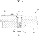
- Fig. 3 is an enlarged view of the main portion of the structure 30 shown in Fig. 2B , in the state before application of current from the constant-current power supply 10 in the structure manufacturing device 100.
- a gap 35 (a gap portion) is formed between the inner peripheral surface of the fastening hole 31a formed in the composite material 31 and the outer peripheral surface 32b of the bolt 32.
- a gap 36 (a gap portion) is formed between the inner peripheral surface of the fastening hole 33a formed in the composite material 33 and the outer peripheral surface 32b of the bolt 32.
- the gap 35 is a portion that has a higher electrical resistance than the composite material 31 and the bolts 32.
- the gap 36 is a portion that has a higher electrical resistance than the composite material 33 and the bolts 32.
- the structure 30 is used, for example, as an integral tank which is a fuel tank integrated with the main wing of an aircraft and has a wing structure that is a sealed structure that does not leak a liquid fuel.
- a head 32a of the bolt 32 is exposed, forming a part of the skin of the main wing. Accordingly, the head 32a of the bolt 32 having higher conductivity than the composite material 31 tends to be struck by lightning.
- a current having a predetermined current value is applied to the gaps 35 and 36 to decrease the electrical resistances of the gaps 35 and 36 such that stroke current easily flows through the composite materials 31 and 33, thereby suppressing generation of sparks.
- the predetermined current value is a current value high enough to carbonize part of a resin material in the composite material 31 defining the gap 35 and part of a resin material in the composite material 33 defining the gap 36, thereby decreasing the electrical resistances of the gaps 35 and 36.
- this predetermined current value is a current value sufficiently lower than a current value assumed to be a stroke current due to a lightning strike, such that the composite materials 31 and 33 are not broken down by the current application.
- Fig. 4 is a graph showing the relationship between the current value that the constant-current power supply 10 shown in Fig. 1 applies to the structure 30, and the application time.
- the horizontal axis indicates the application time lapsed from the initiation of current application across the structure 30 by the constant-current power supply 10 through the constant-current path 20, and the vertical axis indicates the value of the current applied by the constant-current power supply 10 at each application time.
- the maximum current is Imax, and the current at 50 ⁇ s after the initiation of current application is 0.9•Imax.
- the Imax value set by the constant-current power supply 10 satisfies the following equation (1). 0.1 kA ⁇ Imax ⁇ 50 kA
- the Imax value set by the constant-current power supply 10 satisfy the following equation (2). 1 kA ⁇ Imax ⁇ 5 kA
- the application time T from the initiation of current application by the constant-current power supply 10 to the termination of the current application preferably satisfies the following equation (3).
- s indicates second. 300 ⁇ s ⁇ T ⁇ 1 s
- the application time T be set to about 500 ⁇ s.
- a method of manufacturing the structure 30 with the use of the structure manufacturing device 100 according to this embodiment is implemented through the following steps.
- the composite material 31 and the composite material 33 are coupled with each other through the bolts 32 and the nuts 34, thereby forming the structure 30.
- a terminal of the composite material 31 corresponding to one terminal of the structure 30 is connected to the first constant-current path 21, and a terminal of the composite material 33 corresponding to the other terminal of the structure 30 is connected to the second constant-current path 22.
- the constant-current power supply 10 applies a current having the waveform shown in Fig. 4 and applies a current having a predetermined current value to the gaps 35 and 36 (current application step).
- Application of the current having the predetermined current value to the gaps 35 and 36 carbonizes part of a resin material in the composite material 31 defining the gap 35 and part of a resin material in the composite material 33 defining the gap 36, thereby decreasing the electrical resistances of the gaps 35 and 36.
- the structure 30 in which the electrical resistances of the gaps 35 and 36 are reduced is manufactured.
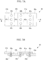
- carbon fibers 31b are exposed on an end surface, corresponding to a cut surface made by cutting, of the composite material 31 composed of a resin material reinforced with the carbon fibers 31b. Multiple carbon fibers 31b exposed on the end surface in this manner are separated from each other without a contact. Accordingly, if a stroke current flows through the composite material 31, discharge in a gap (a gap portion) defined between the adjacent carbon fibers 31b may cause a phenomenon (edge glow phenomenon) in which sparks occur.
- a current having the waveform shown in Fig. 4 is applied from the constant-current power supply 10 to the structure 30. Accordingly, part of a resin layer 31c between the adjacent carbon fibers 31b exposed on the end surface of the composite material 31 is carbonized, and the carbonized part of the resin layer 31c increases the conductivity of the adjacent carbon fibers 31b and decreases the electrical resistance of the gap between the adjacent carbon fibers 31b. Therefore, in the event of a lightning strike, a phenomenon (edge glow phenomenon) in which sparks occur due to discharge is suppressed on the end surface of the structure 30.
- the structure in which current is applied from the constant-current power supply 10 of the structure manufacturing device 100 is made by coupling the composite material 31 and the composite material 33 with each other through the bolts 32, but the structure may have another form.
- a structure 40 is applicable in which a composite material 43a and a composite material 43b are coupled with both ends of the composite material 41a and a composite material 41b is coupled with the end of the composite material 43b.
- the composite material 41a and the composite material 43a are coupled with each other through a bolt 42a inserted into a fastening hole at one end of the composite material 41a and fastened with a nut 44a.
- the composite material 41a and a composite material 43b are coupled with each other through a bolt 42b inserted into a fastening hole at the other end of the composite material 41a and fastened with a nut 44b.
- the composite material 41b and the composite material 43b are coupled with each other through a bolt 42c inserted into a fastening hole at one end of the composite material 41b and fastened with a nut 44c.
- the first constant-current path 21 of the structure manufacturing device 100 is connected to an end of the composite material 43a, which is an end of the structure 40
- the second constant-current path 22 of the structure manufacturing device 100 is connected to an end of the composite material 41b, which is an end of the structure 40.
- the constant-current power supply 10 applies a current having a predetermined current value to the structure 40 through the constant-current path 20, thereby decreasing the electrical resistances of a joint where the bolt 42a for the composite material 41a is inserted, a joint where the bolt 42b for the composite material 41a is inserted, and a joint where the bolt 42c for the composite material 41b is inserted.
- a current having a predetermined current value is applied to the gap 35 (gap portion) present between the composite material 31 (the first conductive member) of the structure 30 and the bolt 32 (the second conductive member), so that the electrical resistance of the gap 35 decreases.
- the current having the predetermined current value is applied to the gap 35 (gap portion) present between the composite material 33 of the structure 30 and the bolt 32, so that the electrical resistance of the gap 35 decreases.
- the structure 30 can be manufactured in which generation of sparks due to lightning strikes is suppressed without increasing the weight of the structure and work for quality management.
- the composite material 31 and the composite material 33 are a material composed of a resin material reinforced with carbon fibers.
- the constant-current power supply 10 is configured to partially carbonize the resin materials in the composite materials 31 and 33 to decrease the electrical resistances of the gaps 35 and 36.
- parts of the resin materials contained in the composite materials 31 and 33 are carbonized to decrease the electrical resistances of the gaps 35 and 36, so that the structure 30 can be manufactured in which generation of sparks due to lightning strikes is suppressed.
- the bolt 32 is a fastening member that is inserted into the fastening hole 31a in the composite material 31 so that the composite material 31 and the composite material 33 (another member) can be coupled with each other. Further, the gap 35 is formed between the fastening hole 31a and the bolt 32.
- part of the fastening hole 31a formed in the composite material 31 is carbonized and the electrical resistance of the gap 35 formed between the fastening hole 31a and the bolt 32 can be reduced.
- the constant-current power supply 10 applies a current with the maximum value in the range of 0.1 kA to 50 kA. It is more preferable that the maximum value of the applied current be in the range of 1 kA to 5kA.
- the electrical resistance of the gap 35 can be decreased while suppressing damage to the composite material 31 and the bolt 32 due to current applied to the gap 35.
- the constant-current power supply 10 applies current such that the current application time T from the initiation to termination of current application is in the range of 300 ⁇ s to 1 s.
- the current application time T is increased, so that the electrical resistance of the gap 35 can be decreased while suppressing damage to the composite material 31 and the bolt 32.
- the composite material 31 and the composite material 33 into which the metal bolt 32 is inserted are carbon fiber reinforced plastics composed of resin materials reinforced with carbon fibers, which is not necessarily the case.
- a metal such as an aluminum alloy (not shown in the drawing) may be used instead of a carbon fiber reinforced plastic.
- a metal has higher conductivity than a carbon fiber reinforced plastic
- a metal may have sufficiently lower conductivity than the bolt 32 when the surface of the metal is oxidized.
- the head 32a of the bolt 32 tends to be struck by lightning.
- a current having a predetermined current value is applied to the gaps 35 and 36 to decrease the electrical resistances of the gaps 35 and 36 such that the stroke current easily flows through the metals, thereby suppressing generation of sparks.
- a predetermined current value is a current value high enough to melt part of the metal defining the gap 35 and part of the metal defining the gap 36, thereby decreasing the electrical resistances of the gaps 35 and 36.
- this predetermined current value is a current value sufficiently lower than a current value assumed to be a stroke current due to a lightning strike, such that the metals are not broken down by the current application.
- the value of the current applied by the constant-current power supply in the structure manufacturing device according to the other embodiment to the structure in which the metals are coupled with each other may be greater than the value of the current applied by the constant-current power supply 10 in the aforementioned structure manufacturing device 100 to the structure 30 in which the composite materials 31 and 33 are coupled with each other. This is because the stroke current flows from the bolt more easily and the risk of damage is lower even with a higher current in the structure in which the metals are coupled with each other.
Landscapes
- Engineering & Computer Science (AREA)
- Aviation & Aerospace Engineering (AREA)
- Mechanical Engineering (AREA)
- General Engineering & Computer Science (AREA)
- Manufacturing & Machinery (AREA)
- Transportation (AREA)
- Connection Of Plates (AREA)
- Moulding By Coating Moulds (AREA)
- Insulators (AREA)
- Current-Collector Devices For Electrically Propelled Vehicles (AREA)
- Spark Plugs (AREA)
- Extrusion Moulding Of Plastics Or The Like (AREA)
- Forging (AREA)
- Lining Or Joining Of Plastics Or The Like (AREA)
Applications Claiming Priority (2)
| Application Number | Priority Date | Filing Date | Title |
|---|---|---|---|
| JP2015073319A JP2016190627A (ja) | 2015-03-31 | 2015-03-31 | 構造体製造装置、構造体製造方法、および構造体 |
| PCT/JP2016/058625 WO2016158476A1 (fr) | 2015-03-31 | 2016-03-18 | Dispositif de production de corps structurel et procédé de production de corps structurel |
Publications (3)
| Publication Number | Publication Date |
|---|---|
| EP3260377A1 true EP3260377A1 (fr) | 2017-12-27 |
| EP3260377A4 EP3260377A4 (fr) | 2018-03-21 |
| EP3260377B1 EP3260377B1 (fr) | 2020-03-04 |
Family
ID=57005683
Family Applications (1)
| Application Number | Title | Priority Date | Filing Date |
|---|---|---|---|
| EP16772359.2A Active EP3260377B1 (fr) | 2015-03-31 | 2016-03-18 | Dispositif de production de corps structurel et procédé de production de corps structurel |
Country Status (7)
| Country | Link |
|---|---|
| US (1) | US20180079527A1 (fr) |
| EP (1) | EP3260377B1 (fr) |
| JP (1) | JP2016190627A (fr) |
| CN (1) | CN107428419B (fr) |
| BR (1) | BR112017020617A2 (fr) |
| CA (1) | CA2980711C (fr) |
| WO (1) | WO2016158476A1 (fr) |
Cited By (1)
| Publication number | Priority date | Publication date | Assignee | Title |
|---|---|---|---|---|
| EP3511579A1 (fr) * | 2018-01-15 | 2019-07-17 | Subaru Corporation | Structure de fixation |
Families Citing this family (2)
| Publication number | Priority date | Publication date | Assignee | Title |
|---|---|---|---|---|
| JP6770987B2 (ja) * | 2018-03-12 | 2020-10-21 | 株式会社Subaru | 複合材構造体、航空機及び雷電流の誘導方法 |
| EP3792173B1 (fr) * | 2019-09-16 | 2022-04-27 | SKF Aerospace France | Système de sécurité destiné à être utilisé dans un aéronef |
Family Cites Families (10)
| Publication number | Priority date | Publication date | Assignee | Title |
|---|---|---|---|---|
| FR2626629B1 (fr) * | 1988-01-29 | 1990-03-09 | Aerospatiale | Procede et dispositif de fixation d'elements de structures d'aeronefs protegees contre la foudre, et outil pour la mise en oeuvre de ce procede |
| US4897143A (en) * | 1988-03-22 | 1990-01-30 | The Boeing Company | Method for conditioning composite structures |
| US4933227A (en) * | 1988-12-30 | 1990-06-12 | Ppg Industries, Inc. | Aircraft windshield |
| JP5237170B2 (ja) * | 2009-03-30 | 2013-07-17 | 三菱重工業株式会社 | 複合材タンク、翼、および、複合材タンクの製造方法 |
| US8791375B2 (en) * | 2010-12-16 | 2014-07-29 | The Boeing Company | Electrically conductive bushing connection to structure for current path |
| JP6113544B2 (ja) * | 2013-03-26 | 2017-04-12 | 三菱重工業株式会社 | 燃料タンク、主翼、航空機胴体、航空機及び移動体 |
| JP6214222B2 (ja) * | 2013-06-04 | 2017-10-18 | ローム株式会社 | 半導体装置の製造方法 |
| JP6509205B2 (ja) * | 2013-06-26 | 2019-05-08 | アーコニック インコーポレイテッドArconic Inc. | 抵抗溶接用ファスナー、装置及び方法 |
| JP5729429B2 (ja) * | 2013-07-29 | 2015-06-03 | トヨタ自動車株式会社 | 接合構造、及び接合構造の製造方法 |
| JP5908052B2 (ja) * | 2014-02-07 | 2016-04-26 | 株式会社神戸製鋼所 | 異材パネル構造体 |
-
2015
- 2015-03-31 JP JP2015073319A patent/JP2016190627A/ja active Pending
-
2016
- 2016-03-18 BR BR112017020617-0A patent/BR112017020617A2/pt not_active IP Right Cessation
- 2016-03-18 EP EP16772359.2A patent/EP3260377B1/fr active Active
- 2016-03-18 CA CA2980711A patent/CA2980711C/fr active Active
- 2016-03-18 CN CN201680018619.2A patent/CN107428419B/zh not_active Expired - Fee Related
- 2016-03-18 US US15/561,162 patent/US20180079527A1/en not_active Abandoned
- 2016-03-18 WO PCT/JP2016/058625 patent/WO2016158476A1/fr not_active Ceased
Cited By (2)
| Publication number | Priority date | Publication date | Assignee | Title |
|---|---|---|---|---|
| EP3511579A1 (fr) * | 2018-01-15 | 2019-07-17 | Subaru Corporation | Structure de fixation |
| US11873113B2 (en) | 2018-01-15 | 2024-01-16 | Subaru Corporation | Fastening structure |
Also Published As
| Publication number | Publication date |
|---|---|
| WO2016158476A1 (fr) | 2016-10-06 |
| CN107428419A (zh) | 2017-12-01 |
| EP3260377A4 (fr) | 2018-03-21 |
| JP2016190627A (ja) | 2016-11-10 |
| CN107428419B (zh) | 2020-12-01 |
| US20180079527A1 (en) | 2018-03-22 |
| CA2980711C (fr) | 2020-12-01 |
| EP3260377B1 (fr) | 2020-03-04 |
| BR112017020617A2 (pt) | 2018-06-26 |
| CA2980711A1 (fr) | 2016-10-06 |
Similar Documents
| Publication | Publication Date | Title |
|---|---|---|
| EP2500272A2 (fr) | Structure de couplage pour composants de cellule d'aéronef | |
| DE102007003276B4 (de) | Luft- und Raumfahrzeug mit einem CFK-Bauteil und einem Metallbauteil, wobei das CFK-Bauteil und das Metallbauteil über wenigstens ein Verbindungselement mit einem Verbindungsabschnitt miteinander verbunden sind | |
| US8186614B2 (en) | Protection against direct lightning strikes in riveted areas of CFRP panels | |
| JP5473892B2 (ja) | 耐雷ファスナ、航空機 | |
| US8587916B2 (en) | Lightning protection fastener, aircraft assembly, and method of manufacturing aircraft assembly component | |
| JP5611097B2 (ja) | 耐雷防爆用ファスナ | |
| EP2551187A1 (fr) | Bouchon, structure fixée utilisant celui-ci et avion doté de ladite structure fixée | |
| EP2909486B1 (fr) | Fabrication d'une liaison hybride | |
| EP2028100B1 (fr) | Attache | |
| JP2009227166A (ja) | 航空機組立品 | |
| RU2641404C2 (ru) | Топливный бак, основные крылья, корпус летательного аппарата, летательный аппарат и транспортное средство | |
| EP3683139B1 (fr) | Surface de commande de vol pour aéronef et procédé de fabrication dudit de surface de commande de vol | |
| EP3260377B1 (fr) | Dispositif de production de corps structurel et procédé de production de corps structurel | |
| JP2016175634A (ja) | 金属間及び複合材料と金属との間の填隙剤 | |
| CA2857837C (fr) | Systemes de fixation assurant une protection contre les effets electromagnetiques | |
| JP2011051517A (ja) | 航空機の翼 | |
| DE102012001859B4 (de) | Verbindungsanordnung und Verfahren zum Verbinden wenigstens eines ersten Bauteils aus einem kohlefaserverstärkten Verbundwerkstoff mit wenigstens einem zweiten Bauteil | |
| EP2979976B1 (fr) | Réservoir de carburant, ailes principales, fuselage d'aéronef, aéronef et corps mobile | |
| US20210372373A1 (en) | Spar structure with integrated down conductor element for lightning protection system | |
| DE102010040338A1 (de) | Befestigungselement für blitzschlaggefährdete Bauteile | |
| EP2722531A1 (fr) | Fabrication d'une liaison hybride | |
| JP2013163473A (ja) | 耐雷ファスナ、航空機、治具、航空機の組立方法 |
Legal Events
| Date | Code | Title | Description |
|---|---|---|---|
| STAA | Information on the status of an ep patent application or granted ep patent |
Free format text: STATUS: THE INTERNATIONAL PUBLICATION HAS BEEN MADE |
|
| PUAI | Public reference made under article 153(3) epc to a published international application that has entered the european phase |
Free format text: ORIGINAL CODE: 0009012 |
|
| STAA | Information on the status of an ep patent application or granted ep patent |
Free format text: STATUS: REQUEST FOR EXAMINATION WAS MADE |
|
| 17P | Request for examination filed |
Effective date: 20170918 |
|
| AK | Designated contracting states |
Kind code of ref document: A1 Designated state(s): AL AT BE BG CH CY CZ DE DK EE ES FI FR GB GR HR HU IE IS IT LI LT LU LV MC MK MT NL NO PL PT RO RS SE SI SK SM TR |
|
| AX | Request for extension of the european patent |
Extension state: BA ME |
|
| A4 | Supplementary search report drawn up and despatched |
Effective date: 20180220 |
|
| RIC1 | Information provided on ipc code assigned before grant |
Ipc: B64C 1/12 20060101ALI20180214BHEP Ipc: B64C 1/00 20060101ALI20180214BHEP Ipc: B32B 7/08 20060101ALI20180214BHEP Ipc: B64F 5/00 20170101AFI20180214BHEP Ipc: B64D 45/02 20060101ALI20180214BHEP Ipc: F16B 1/00 20060101ALN20180214BHEP Ipc: F16B 5/02 20060101ALI20180214BHEP |
|
| DAV | Request for validation of the european patent (deleted) | ||
| DAX | Request for extension of the european patent (deleted) | ||
| RIC1 | Information provided on ipc code assigned before grant |
Ipc: B64C 1/00 20060101ALI20190822BHEP Ipc: F16B 1/00 20060101ALN20190822BHEP Ipc: B64C 1/12 20060101ALI20190822BHEP Ipc: B64D 45/02 20060101ALI20190822BHEP Ipc: B32B 7/08 20190101ALI20190822BHEP Ipc: F16B 5/02 20060101ALI20190822BHEP Ipc: B64F 5/00 20170101AFI20190822BHEP |
|
| GRAP | Despatch of communication of intention to grant a patent |
Free format text: ORIGINAL CODE: EPIDOSNIGR1 |
|
| STAA | Information on the status of an ep patent application or granted ep patent |
Free format text: STATUS: GRANT OF PATENT IS INTENDED |
|
| INTG | Intention to grant announced |
Effective date: 20191002 |
|
| RIC1 | Information provided on ipc code assigned before grant |
Ipc: B64C 1/00 20060101ALI20190924BHEP Ipc: B64C 1/12 20060101ALI20190924BHEP Ipc: B64D 45/02 20060101ALI20190924BHEP Ipc: B64F 5/00 20170101AFI20190924BHEP Ipc: F16B 1/00 20060101ALN20190924BHEP Ipc: B32B 7/08 20190101ALI20190924BHEP Ipc: F16B 5/02 20060101ALI20190924BHEP |
|
| GRAS | Grant fee paid |
Free format text: ORIGINAL CODE: EPIDOSNIGR3 |
|
| GRAA | (expected) grant |
Free format text: ORIGINAL CODE: 0009210 |
|
| STAA | Information on the status of an ep patent application or granted ep patent |
Free format text: STATUS: THE PATENT HAS BEEN GRANTED |
|
| AK | Designated contracting states |
Kind code of ref document: B1 Designated state(s): AL AT BE BG CH CY CZ DE DK EE ES FI FR GB GR HR HU IE IS IT LI LT LU LV MC MK MT NL NO PL PT RO RS SE SI SK SM TR |
|
| REG | Reference to a national code |
Ref country code: GB Ref legal event code: FG4D |
|
| REG | Reference to a national code |
Ref country code: CH Ref legal event code: EP |
|
| REG | Reference to a national code |
Ref country code: AT Ref legal event code: REF Ref document number: 1240097 Country of ref document: AT Kind code of ref document: T Effective date: 20200315 |
|
| REG | Reference to a national code |
Ref country code: DE Ref legal event code: R096 Ref document number: 602016031132 Country of ref document: DE |
|
| REG | Reference to a national code |
Ref country code: IE Ref legal event code: FG4D |
|
| PG25 | Lapsed in a contracting state [announced via postgrant information from national office to epo] |
Ref country code: NO Free format text: LAPSE BECAUSE OF FAILURE TO SUBMIT A TRANSLATION OF THE DESCRIPTION OR TO PAY THE FEE WITHIN THE PRESCRIBED TIME-LIMIT Effective date: 20200604 Ref country code: RS Free format text: LAPSE BECAUSE OF FAILURE TO SUBMIT A TRANSLATION OF THE DESCRIPTION OR TO PAY THE FEE WITHIN THE PRESCRIBED TIME-LIMIT Effective date: 20200304 Ref country code: FI Free format text: LAPSE BECAUSE OF FAILURE TO SUBMIT A TRANSLATION OF THE DESCRIPTION OR TO PAY THE FEE WITHIN THE PRESCRIBED TIME-LIMIT Effective date: 20200304 |
|
| REG | Reference to a national code |
Ref country code: NL Ref legal event code: MP Effective date: 20200304 |
|
| PG25 | Lapsed in a contracting state [announced via postgrant information from national office to epo] |
Ref country code: GR Free format text: LAPSE BECAUSE OF FAILURE TO SUBMIT A TRANSLATION OF THE DESCRIPTION OR TO PAY THE FEE WITHIN THE PRESCRIBED TIME-LIMIT Effective date: 20200605 Ref country code: HR Free format text: LAPSE BECAUSE OF FAILURE TO SUBMIT A TRANSLATION OF THE DESCRIPTION OR TO PAY THE FEE WITHIN THE PRESCRIBED TIME-LIMIT Effective date: 20200304 Ref country code: BG Free format text: LAPSE BECAUSE OF FAILURE TO SUBMIT A TRANSLATION OF THE DESCRIPTION OR TO PAY THE FEE WITHIN THE PRESCRIBED TIME-LIMIT Effective date: 20200604 Ref country code: SE Free format text: LAPSE BECAUSE OF FAILURE TO SUBMIT A TRANSLATION OF THE DESCRIPTION OR TO PAY THE FEE WITHIN THE PRESCRIBED TIME-LIMIT Effective date: 20200304 Ref country code: LV Free format text: LAPSE BECAUSE OF FAILURE TO SUBMIT A TRANSLATION OF THE DESCRIPTION OR TO PAY THE FEE WITHIN THE PRESCRIBED TIME-LIMIT Effective date: 20200304 |
|
| REG | Reference to a national code |
Ref country code: LT Ref legal event code: MG4D |
|
| PG25 | Lapsed in a contracting state [announced via postgrant information from national office to epo] |
Ref country code: NL Free format text: LAPSE BECAUSE OF FAILURE TO SUBMIT A TRANSLATION OF THE DESCRIPTION OR TO PAY THE FEE WITHIN THE PRESCRIBED TIME-LIMIT Effective date: 20200304 |
|
| PG25 | Lapsed in a contracting state [announced via postgrant information from national office to epo] |
Ref country code: LT Free format text: LAPSE BECAUSE OF FAILURE TO SUBMIT A TRANSLATION OF THE DESCRIPTION OR TO PAY THE FEE WITHIN THE PRESCRIBED TIME-LIMIT Effective date: 20200304 Ref country code: PT Free format text: LAPSE BECAUSE OF FAILURE TO SUBMIT A TRANSLATION OF THE DESCRIPTION OR TO PAY THE FEE WITHIN THE PRESCRIBED TIME-LIMIT Effective date: 20200729 Ref country code: EE Free format text: LAPSE BECAUSE OF FAILURE TO SUBMIT A TRANSLATION OF THE DESCRIPTION OR TO PAY THE FEE WITHIN THE PRESCRIBED TIME-LIMIT Effective date: 20200304 Ref country code: SM Free format text: LAPSE BECAUSE OF FAILURE TO SUBMIT A TRANSLATION OF THE DESCRIPTION OR TO PAY THE FEE WITHIN THE PRESCRIBED TIME-LIMIT Effective date: 20200304 Ref country code: CZ Free format text: LAPSE BECAUSE OF FAILURE TO SUBMIT A TRANSLATION OF THE DESCRIPTION OR TO PAY THE FEE WITHIN THE PRESCRIBED TIME-LIMIT Effective date: 20200304 Ref country code: IS Free format text: LAPSE BECAUSE OF FAILURE TO SUBMIT A TRANSLATION OF THE DESCRIPTION OR TO PAY THE FEE WITHIN THE PRESCRIBED TIME-LIMIT Effective date: 20200704 Ref country code: RO Free format text: LAPSE BECAUSE OF FAILURE TO SUBMIT A TRANSLATION OF THE DESCRIPTION OR TO PAY THE FEE WITHIN THE PRESCRIBED TIME-LIMIT Effective date: 20200304 Ref country code: ES Free format text: LAPSE BECAUSE OF FAILURE TO SUBMIT A TRANSLATION OF THE DESCRIPTION OR TO PAY THE FEE WITHIN THE PRESCRIBED TIME-LIMIT Effective date: 20200304 Ref country code: SK Free format text: LAPSE BECAUSE OF FAILURE TO SUBMIT A TRANSLATION OF THE DESCRIPTION OR TO PAY THE FEE WITHIN THE PRESCRIBED TIME-LIMIT Effective date: 20200304 |
|
| REG | Reference to a national code |
Ref country code: CH Ref legal event code: PL |
|
| REG | Reference to a national code |
Ref country code: AT Ref legal event code: MK05 Ref document number: 1240097 Country of ref document: AT Kind code of ref document: T Effective date: 20200304 |
|
| REG | Reference to a national code |
Ref country code: DE Ref legal event code: R097 Ref document number: 602016031132 Country of ref document: DE |
|
| REG | Reference to a national code |
Ref country code: BE Ref legal event code: MM Effective date: 20200331 |
|
| PG25 | Lapsed in a contracting state [announced via postgrant information from national office to epo] |
Ref country code: MC Free format text: LAPSE BECAUSE OF FAILURE TO SUBMIT A TRANSLATION OF THE DESCRIPTION OR TO PAY THE FEE WITHIN THE PRESCRIBED TIME-LIMIT Effective date: 20200304 Ref country code: LU Free format text: LAPSE BECAUSE OF NON-PAYMENT OF DUE FEES Effective date: 20200318 |
|
| PLBE | No opposition filed within time limit |
Free format text: ORIGINAL CODE: 0009261 |
|
| STAA | Information on the status of an ep patent application or granted ep patent |
Free format text: STATUS: NO OPPOSITION FILED WITHIN TIME LIMIT |
|
| PG25 | Lapsed in a contracting state [announced via postgrant information from national office to epo] |
Ref country code: IT Free format text: LAPSE BECAUSE OF FAILURE TO SUBMIT A TRANSLATION OF THE DESCRIPTION OR TO PAY THE FEE WITHIN THE PRESCRIBED TIME-LIMIT Effective date: 20200304 Ref country code: AT Free format text: LAPSE BECAUSE OF FAILURE TO SUBMIT A TRANSLATION OF THE DESCRIPTION OR TO PAY THE FEE WITHIN THE PRESCRIBED TIME-LIMIT Effective date: 20200304 Ref country code: DK Free format text: LAPSE BECAUSE OF FAILURE TO SUBMIT A TRANSLATION OF THE DESCRIPTION OR TO PAY THE FEE WITHIN THE PRESCRIBED TIME-LIMIT Effective date: 20200304 Ref country code: CH Free format text: LAPSE BECAUSE OF NON-PAYMENT OF DUE FEES Effective date: 20200331 Ref country code: IE Free format text: LAPSE BECAUSE OF NON-PAYMENT OF DUE FEES Effective date: 20200318 Ref country code: LI Free format text: LAPSE BECAUSE OF NON-PAYMENT OF DUE FEES Effective date: 20200331 |
|
| 26N | No opposition filed |
Effective date: 20201207 |
|
| PG25 | Lapsed in a contracting state [announced via postgrant information from national office to epo] |
Ref country code: BE Free format text: LAPSE BECAUSE OF NON-PAYMENT OF DUE FEES Effective date: 20200331 Ref country code: PL Free format text: LAPSE BECAUSE OF FAILURE TO SUBMIT A TRANSLATION OF THE DESCRIPTION OR TO PAY THE FEE WITHIN THE PRESCRIBED TIME-LIMIT Effective date: 20200304 Ref country code: SI Free format text: LAPSE BECAUSE OF FAILURE TO SUBMIT A TRANSLATION OF THE DESCRIPTION OR TO PAY THE FEE WITHIN THE PRESCRIBED TIME-LIMIT Effective date: 20200304 |
|
| PG25 | Lapsed in a contracting state [announced via postgrant information from national office to epo] |
Ref country code: TR Free format text: LAPSE BECAUSE OF FAILURE TO SUBMIT A TRANSLATION OF THE DESCRIPTION OR TO PAY THE FEE WITHIN THE PRESCRIBED TIME-LIMIT Effective date: 20200304 Ref country code: MT Free format text: LAPSE BECAUSE OF FAILURE TO SUBMIT A TRANSLATION OF THE DESCRIPTION OR TO PAY THE FEE WITHIN THE PRESCRIBED TIME-LIMIT Effective date: 20200304 Ref country code: CY Free format text: LAPSE BECAUSE OF FAILURE TO SUBMIT A TRANSLATION OF THE DESCRIPTION OR TO PAY THE FEE WITHIN THE PRESCRIBED TIME-LIMIT Effective date: 20200304 |
|
| PG25 | Lapsed in a contracting state [announced via postgrant information from national office to epo] |
Ref country code: MK Free format text: LAPSE BECAUSE OF FAILURE TO SUBMIT A TRANSLATION OF THE DESCRIPTION OR TO PAY THE FEE WITHIN THE PRESCRIBED TIME-LIMIT Effective date: 20200304 Ref country code: AL Free format text: LAPSE BECAUSE OF FAILURE TO SUBMIT A TRANSLATION OF THE DESCRIPTION OR TO PAY THE FEE WITHIN THE PRESCRIBED TIME-LIMIT Effective date: 20200304 |
|
| PGFP | Annual fee paid to national office [announced via postgrant information from national office to epo] |
Ref country code: GB Payment date: 20260202 Year of fee payment: 11 |
|
| PGFP | Annual fee paid to national office [announced via postgrant information from national office to epo] |
Ref country code: DE Payment date: 20260128 Year of fee payment: 11 |
|
| PGFP | Annual fee paid to national office [announced via postgrant information from national office to epo] |
Ref country code: FR Payment date: 20260209 Year of fee payment: 11 |