EP3260399A1 - Dispositif de préhension destiné à saisir plusieurs marchandises, système de maniement de plusieurs marchandises et procédé de manipulation de plusieurs marchandises - Google Patents
Dispositif de préhension destiné à saisir plusieurs marchandises, système de maniement de plusieurs marchandises et procédé de manipulation de plusieurs marchandises Download PDFInfo
- Publication number
- EP3260399A1 EP3260399A1 EP17175487.2A EP17175487A EP3260399A1 EP 3260399 A1 EP3260399 A1 EP 3260399A1 EP 17175487 A EP17175487 A EP 17175487A EP 3260399 A1 EP3260399 A1 EP 3260399A1
- Authority
- EP
- European Patent Office
- Prior art keywords
- gripping
- carriage
- gripping means
- piece goods
- units
- Prior art date
- Legal status (The legal status is an assumption and is not a legal conclusion. Google has not performed a legal analysis and makes no representation as to the accuracy of the status listed.)
- Granted
Links
Images



Classifications
-
- B—PERFORMING OPERATIONS; TRANSPORTING
- B65—CONVEYING; PACKING; STORING; HANDLING THIN OR FILAMENTARY MATERIAL
- B65G—TRANSPORT OR STORAGE DEVICES, e.g. CONVEYORS FOR LOADING OR TIPPING, SHOP CONVEYOR SYSTEMS OR PNEUMATIC TUBE CONVEYORS
- B65G47/00—Article or material-handling devices associated with conveyors; Methods employing such devices
- B65G47/74—Feeding, transfer, or discharging devices of particular kinds or types
- B65G47/90—Devices for picking-up and depositing articles or materials
- B65G47/907—Devices for picking-up and depositing articles or materials with at least two picking-up heads
-
- B—PERFORMING OPERATIONS; TRANSPORTING
- B25—HAND TOOLS; PORTABLE POWER-DRIVEN TOOLS; MANIPULATORS
- B25J—MANIPULATORS; CHAMBERS PROVIDED WITH MANIPULATION DEVICES
- B25J15/00—Gripping heads and other end effectors
- B25J15/0052—Gripping heads and other end effectors multiple gripper units or multiple end effectors
-
- B—PERFORMING OPERATIONS; TRANSPORTING
- B25—HAND TOOLS; PORTABLE POWER-DRIVEN TOOLS; MANIPULATORS
- B25J—MANIPULATORS; CHAMBERS PROVIDED WITH MANIPULATION DEVICES
- B25J15/00—Gripping heads and other end effectors
- B25J15/02—Gripping heads and other end effectors servo-actuated
- B25J15/0253—Gripping heads and other end effectors servo-actuated comprising parallel grippers
- B25J15/0286—Gripping heads and other end effectors servo-actuated comprising parallel grippers actuated by chains, cables or ribbons
-
- B—PERFORMING OPERATIONS; TRANSPORTING
- B65—CONVEYING; PACKING; STORING; HANDLING THIN OR FILAMENTARY MATERIAL
- B65G—TRANSPORT OR STORAGE DEVICES, e.g. CONVEYORS FOR LOADING OR TIPPING, SHOP CONVEYOR SYSTEMS OR PNEUMATIC TUBE CONVEYORS
- B65G2207/00—Indexing codes relating to constructional details, configuration and additional features of a handling device, e.g. Conveyors
- B65G2207/08—Adjustable and/or adaptable to the article size
-
- B—PERFORMING OPERATIONS; TRANSPORTING
- B65—CONVEYING; PACKING; STORING; HANDLING THIN OR FILAMENTARY MATERIAL
- B65G—TRANSPORT OR STORAGE DEVICES, e.g. CONVEYORS FOR LOADING OR TIPPING, SHOP CONVEYOR SYSTEMS OR PNEUMATIC TUBE CONVEYORS
- B65G47/00—Article or material-handling devices associated with conveyors; Methods employing such devices
- B65G47/22—Devices influencing the relative position or the attitude of articles during transit by conveyors
- B65G47/26—Devices influencing the relative position or the attitude of articles during transit by conveyors arranging the articles, e.g. varying spacing between individual articles
Definitions
- the present invention relates to a gripping device for detecting a plurality of packaged goods with at least two gripping units, a system for handling a plurality of packaged goods and a method for manipulating a plurality of packaged goods via a gripping device having at least two gripping units.
- Known packaging or palletizing systems for stacking and palletizing objects such as packages or containers with several articles such as beverage containers usually have horizontal conveyors with conveyor belts on which the packages or packages are conveyed in an uninterrupted or irregular sequence and spaced to a handling device.
- Known handling devices which effect such a displacement, alignment and / or rotation of individual piece goods or containers can also be provided with grippers, for example, suspended from a gantry system and moved in a defined range of motion, rotated and also moved in the vertical direction can be used to lift individual piece goods or containers for turning and / or moving.
- the grippers can be arranged in further known embodiments also on multi-axis robot arms, which are placed laterally on the horizontal conveyors.
- Such gripping devices are approximately from the EP 2 388 216 A1 known.
- the gripping device disclosed in the EP patent application has two opposing gripping means which can be delivered for receiving piece goods. If the gripping device unintentionally rests on a bottom surface, then the two opposing gripping means can come loose from a carrier, which is intended to counteract damage to the gripping device.
- the gripping device disclosed in the DE application comprises two gripping arms for gripping objects.
- One of the two gripping arms can be connected to a vehicle.
- the further gripper arm is used to open and close the gripping device via an actuator.
- An object of the invention can therefore be seen to provide a generic gripping device or a generic system and methods are available, which have a high flexibility in a supply of articles with different relative distances from each other and / or different geometries.
- the gripping device and the system should have a simple structure. Furthermore, the method should be easy to implement.
- the invention relates to a gripping device for detecting a plurality of piece goods.
- the piece goods which can be detected by means of the gripping device, can be formed for example by beverage containers or by a plurality of beverage containers combined into a container.
- the gripping device comprises at least two gripping units.
- the at least two gripping units each have a first gripping means and a second gripping means opposite to the respective first gripping means, which respective first gripping means cooperates with the respective second gripping means for clamping and / or form-locking gripping of a respective piece goods.
- the gripping device may also have more than two gripping units.
- the gripping device has three gripping units each having a first gripping means and a second gripping means opposite the respective first gripping means, wherein a first gripping means and a respective second gripping means opposite the respective first gripping means for detecting a respective piece goods cooperate.
- the first gripping means and the second gripping means may form a contact area for piece goods in the region of their free end.
- the respective piece goods may come into contact with a contact region of a first gripping means and a contact region of a respective second gripping means opposite the first gripping means.
- the respective contact region may be formed elastically yielding. Accordingly, at least one first gripping means and / or at least one second gripping means in the contact region may have at least one abutment formed by rubber or other elastic compliant materials.
- first gripping means and the second gripping means are oriented inclined in the direction of a respective piece goods to be picked or in the direction of the respective opposite gripping means.
- first gripping means of the at least two gripping units and / or the second gripping means of the at least two gripping units are mechanically coupled to one another for a common feed movement.
- a movement of a first gripping means of a first gripping unit can thereby be accompanied by a time-synchronous movement of a first gripping means of a second gripping unit.
- the first gripping means can thus be rigidly coupled or substantially rigidly coupled to one another.
- the second gripping means may be rigidly coupled or substantially rigidly coupled with each other.
- the gripping device comprises a suspension or a common suspension, on which the at least two gripping units are arranged to be movable. Accordingly, the at least two gripping units or the first gripping means and / or the second gripping means of the at least two gripping units be moved relative to the suspension at their respective feed movement.
- the at least two gripping units can thus be carried by the suspension or by the common suspension.
- the gripping device may optionally be in communication with a handling device described below.
- the suspension can therefore provide a flange or a coupling for the handling device described below.
- a longitudinal axis of the suspension may have an at least approximately horizontal orientation.
- first gripping means of the at least two gripping units are fixed to a common first carriage and / or that the second gripping means of the at least two gripping units are fixed to a common second carriage, which first carriage and / or which second carriage with a Linear guide in connection.
- the first carriage and the second carriage may therefore be independently movable along the linear guide, if necessary.
- a direction of movement of the first carriage may be oriented parallel to a direction of movement of the second carriage.
- the gripping device comprises at least one circumferentially guided in particular designed as a belt actuator, to which the first carriage and / or the second carriage are mechanically coupled for the respective feed movement.
- the at least one circumferentially guided actuator can thus be formed by at least one belt. It is also conceivable that the at least one circumferentially guided actuator is designed as a chain drive.
- the gripping device may comprise a deflection roller and a drive roller, around which the at least one actuator is guided circumferentially.
- the deflection roller may have an axis of rotation, the drive shaft an axis of rotation, wherein the axis of rotation and the axis of rotation are oriented parallel to each other.
- the drive roller can be connected to an actuator or driven in rotation by the handling device described below.
- An actuator of the handling device can rotate the drive roller for a feed movement of the first gripping means and / or the second gripping means for this purpose.
- the deflection roller and / or the drive roller can on the suspension already mentioned be attached or stored.
- the at least one actuator may comprise at least one servomotor for driving the at least one actuator or for rotating the drive roller.
- the actuator or the servo motor can be seated on the suspension or fixed to the suspension.
- the at least one circumferentially guided actuator or the at least one belt can run parallel to the longitudinal extent of the suspension and / or parallel to a direction of movement of the first carriage and / or the second carriage. Accordingly, the at least one actuator or the at least one belt may extend parallel to the guide direction of the linear guide.
- the gripping device comprises a specific, in particular designed as a belt circumferentially guided actuator, to which both the first carriage and the second carriage for the respective feed movement are each mechanically coupled.
- the gripping device comprises a deflection roller and a drive roller, around which the at least one specific actuator or the specific belt is guided circumferentially.
- the drive roller may, as previously described, continue to communicate with an actuator or provide a flange for connection to an actuator or for connection to a handling device.
- the first carriage and the second carriage may be coupled to each other in motion via the particular rotatably guided actuator designed in particular as a belt.
- a clamping connection can be provided for the first carriage, by means of which the first carriage is coupled to the specific, in particular designed as a belt circumferentially guided actuator.
- a clamping connection can be provided, by means of which the second carriage is coupled to the particular designed in particular as a belt circumferentially guided actuator.
- the first slide and the second slide can be mechanically coupled in particular by means of a respective clamping connection on opposite sides of the particular designed in particular as a belt circumferentially guided actuator.
- the particular actuator or belt may extend to less than two-thirds along the length of the suspension.
- first gripping means of the first carriage are selectively fixable in at least two different relative distances to each other on the first carriage and / or that the second gripping means of the second carriage are selectively fixable in at least two different relative spacings to each other on the second carriage.
- at least one first gripping means and / or at least one second gripping means can be detachably fixed to the respective slide.
- the gripping device can comprise detent and / or snap and / or clamping connections in order to detachably fix the at least one first gripping means and / or the at least one second gripping means to the respective slide in the respective relative spacing to the further first and second gripping means
- the first carriage and / or the second carriage may provide a plurality of predetermined positions to fix the first gripping means and the second gripping means, respectively, in a desired relative spaced relation to each other on the respective first carriage and second carriage, respectively.
- the invention also relates to a system for handling general cargo.
- the system comprises a handling device with a gripping device as described above.
- the system comprises at least one transport device by means of which a multiplicity of piece goods can be fed to a working area of the handling device and can be moved out of the working area of the handling device.
- the system also includes a control unit, via which the handling device for detecting and manipulating piece goods with the aid of its gripping device can be controlled.
- the handling device is designed here as a delta kinematics robot.
- the handling device is designed as a multi-axis robot.
- the handling device is designed as a portal system, by means of which the gripping device can be moved for manipulating piece goods.
- the system may include a handling device.
- the system comprises a plurality of handling devices with a respective gripping device and / or a handling device with a plurality of gripping devices, wherein the plurality of handling devices or the plurality of gripping devices for Manipulating piece goods interact or are in operative connection with each other.
- the system can be designed as a turning and distribution system for piece goods. It may also be that the system is designed to produce a palletizable layer from a plurality of piece goods or to produce a pre-grouping for a palletizable layer from a plurality of piece goods.
- the invention further relates to a method for manipulating a plurality of piece goods via a gripping device with at least two gripping units.
- a gripping device with at least two gripping units.
- the first mechanical coupling comprises a first carriage and in which the second mechanical coupling comprises a second carriage, wherein the first carriage and / or the second carriage for or during execution of the respective feed movement along be moved at least one linear guide.
- the first carriage and the second carriage can be moved or moved parallel to each other.
- first carriage and / or the second carriage are fastened to at least one circumferentially guided actuator, preferably designed as a belt, wherein the first carriage and / or the second carriage can be moved via the at least one actuator along the be moved at least one linear guide.
- first carriage and the second carriage may be fastened to a common certain, preferably belt-shaped, rotatably guided actuator.
- the trained as a belt circumferentially guided certain actuator can be driven, resulting in the first gripping means and the second gripping means time synchronously initiate a feed movement.
- the preferably designed as a belt circumferentially guided certain actuator can be stopped.
- the preferably designed as a belt circumferentially guided certain actuator can be actuated actuated.
- a movement of the first carriage can begin at least approximately simultaneously with a movement of the second carriage.
- a movement of the first carriage may end at least approximately simultaneously with a movement of the second carriage.
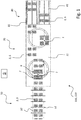
- the Fig. 1 shows a schematic view of a conceivable embodiment for the inventive system 100.
- the system 100 is formed as a distribution system 110 and includes, as in Fig. 1 To recognize left side, a one-piece 50 with several push bar 51 and a horizontal conveyor 52, on which horizontal conveyor 52 as a container 3 with a plurality of beverage containers formed piece goods 5 are transported in two parallel rows.
- the push bars 51 are positioned between successive piece goods 5, each come into contact with a cargo 5 of the two parallel rows and align the two piece goods 5 side by side or perpendicular to a transport direction of the horizontal conveyor 52 in alignment with each other.
- the aligned or divided piece goods 5 are then fed to a manipulation area 70 via the horizontal conveyor 52 of the divider 50, which is immediately downstream of the divider 50 in the transport direction of the piece goods 5 or container 3.
- the manipulation area 70 has two gripping devices 1, which are part of a respective in Fig. 1 are not formed with handling device shown and can be moved by means of the respective handling device.
- the handling devices can be designed, for example, as a gantry system or by a respective delta kinematics robot.
- the gripping devices 1 have, as in subsequent Figures 5 and 6 shown and described in detail, in each case via two gripping units 7 and 9, each with a first gripping means 15 and in each case one opposite the first gripping means 15 second gripping means 17th
- successive piece goods 5 which have entered the manipulation area 70, are detected by means of the gripping units 7 and 9 of a respective gripping device 1 and subsequently manipulated, the relative positions of the gripping units 7 and 9 or the first gripping means 15 and the second gripping means 17 must be indicated the spacings of successive piece goods 5 must be adjusted in order to receive successive piece goods 5 by means of the gripping units 7 and 9 can.
- the gripping devices 1 have been previously exchanged in order to ensure a targeted detection of means 50 of the one-piece 50 relative to each other spaced successive cargo 5.
- the invention makes it possible to adapt the gripping device 1 to different distances of successive piece goods 5 or pitches of successive piece goods 5 without complete replacement of the gripping devices 1. Also, by means of the gripping device according to the invention 1 piece goods 5 with different geometries under uncomplicated adaptation of the gripping device 1 to the respective geometry targeted be captured and manipulated.
- FIG. 1 it can be seen that individual piece goods 5 or bundles 3 in the manipulation area 70 are offset obliquely to their direction of movement by means of the gripping devices 1.
- an outlet 80 with a plurality of guide rails 81, wherein immediately adjacent guide railings 81 form an alley for piece goods 5 or for containers 3.
- the transfer of the piece goods 5 thus takes place in such a way that the piece goods 5 are distributed uniformly in terms of their number onto the lanes formed between the guide rails 81.
- the handling devices which move the gripping devices 1 for displacing or distributing the piece goods 5 or containers 3, are connected to a control unit S.
- the control unit S causes a coordinated movement of both gripping devices 1 and both handling devices, which are part of the gripping devices 1, so that both gripping devices 1 selectively piece goods 5 and 3 accept containers and matched to each formed between each immediately adjacent guide rails 81 alleys can distribute.
- the gripping device 1 is in Fig. 1 thus formed as part of a distribution system 110.
- the embodiment is to be understood merely as an example, so that the gripping device 1 can also be used for other systems 100, for example for producing a palletizable layer from a plurality of piece goods 5 or a pre-grouping of a palletizable layer of piece goods 5.
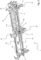
- Fig. 2 shows a schematic perspective view obliquely from below on a first embodiment of a gripping device according to the invention 1.
- the gripping device. 1 according to the embodiment Fig. 2 can after 100 for a system Fig. 1 Find use.
- the gripping device 1 has a suspension 10. With the suspension 10 are a first carriage 20 and a second carriage 22 via a respective linear guide 12 and 14 in conjunction. The first carriage 20 and the second carriage 22 can thus be moved along the suspension 10 or along the longitudinal extension of the suspension 10 with the aid of the respective linear guide 12 or 14. The suspension carries the first carriage 20 and the second carriage 22.
- the gripping device 1 additionally comprises a first gripping unit 7 and a second gripping unit 9 (cf. Figures 5 and 6 ), which for reasons of clarity in the FIGS. 2 to 4 not shown.
- Both the first gripping unit 7 and the second gripping unit 9 each have a first gripping means 15 and a second gripping means 17, which respective second gripping means 17 opposite the respective first gripping means 15 and cooperates with the respective first gripping means 15 for detecting cargo 5.
- the schematic perspective view of Fig. 2 indicates that the first carriage 20 has a predetermined position 11 for a first gripping means 15. At the predetermined position 11 thus a first gripping means 15 is arranged.
- the first carriage 20 has a first attachment position 6 and a second attachment position 8 for a further first gripping means 15.
- the further first gripping means 15 can thus be arranged selectively in the first attachment position 6 or in the second attachment position 8 on the first carriage 20.
- the first fastening position 6 or the second fastening position 8 can be calculated taking into account a relative distance between successive piece goods 5 or a pitch (cf. Fig. 1 ), after which the further first gripping means 15 is selectively fixed in the first fastening position 6 or in the second fastening position 8 on the first slide 20.
- FIG. 5 A synopsis of these figures shows the respective further first gripping means 15, which in Fig. 5 is fixed in the first attachment position 6 on the first carriage 20 and in Fig. 6 is set in the second attachment position 8 on the first carriage 20.
- the first gripping means 15 have in Figures 5 and 6 a different relative distance to each other, which is maintained upon detection and manipulation of a respective item 5 or container 3.
- the second carriage 22 has a predetermined position 13 for a second gripping means 17. At the predetermined position 13 thus a second gripping means 17 is fixed.
- the second carriage 22 also has a first attachment position 6 'and a second attachment position 8' for a further second gripping means 17.
- the further second gripping means 17 can selectively in the first attachment position 6 'or in the second attachment position 8' and possibly taking into account Division distance of successive cargo 5 on the second carriage 22 are arranged.
- a drive roller 60 and a guide roller 62 are also attached.
- a specific and formed as a belt 4 actuator 2 is guided circumferentially.
- a rotation axis of the drive roller 60 and a rotation axis of the deflection roller 62 are parallel to each other.
- Both the first carriage 20 and the second carriage 22 are mechanically coupled to the actuator 2 and the belt 4 so that the first carriage 20 and the second carriage 22 for performing a feed movement of their respective first and second gripping means 15 and 17 means of the actuator 2 or by means of the belt 4 can be moved.
- the drive roller 60 can be driven in rotation via an actuator, not shown, or via a handling device, not shown, and, as a result, the actuator 2 or the belt 4 move.
- the Fig. 3 shows a schematic view from below of the embodiment of a gripping device 1 from Fig. 2 ,
- Fig. 2 Again, the predetermined positions 11 and 13 of the first carriage 20 and the second carriage 22 for the respective first and second gripping means 15 and 17 can be seen.
- Fig. 2 recognize again the first attachment positions 6 and 6 'and the second attachment positions 8 and 8', to which the further first and second gripping means 15 and 17 can be fixed.
- the actuator 2 or the belt 4 extends parallel to the longitudinal axis of the suspension 10 and parallel to a direction of movement of the first carriage 20 and the second carriage 22nd
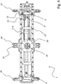
- Fig. 4 shows a schematic top view of the embodiment of a gripping device 1 from Figures 2 and 3 ,
- a flange portion 18 can be seen, to which an actuator or a handling device for rotating movement of the drive roller 60 (see. Fig. 2 ) can be coupled.
- paragraph 30 shows Fig. 4
- the actuator 2 and the belt 4 related clamping means via which the first carriage 20 on the actuator 2 or belt 4th is fixed.
- reference numeral 32 also clamping means are shown, via which the second carriage 22 on the actuator 2 or belt 4 is fixed.
- the clamping means 30, via which the first carriage 20 is fixed to the actuator 2 or belt 4 and the clamping means 32, via which the second carriage 22 is fixed to the actuator 2 or belt 4, are on opposite sides of the common actuator 2 and of the common belt 4 is positioned.
- the first carriage 20 and the second carriage 22 can be moved in a time-synchronized manner.
- the first gripping means 15 and the second gripping means 17 are moved synchronously in time as part of their advancing movement (cf. Fig. 5 ).
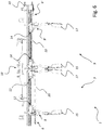
- the Fig. 5 shows a schematic side view of the embodiment of a gripping device 1 of the FIGS. 2 to 4 ,
- the two gripping units 7 and 9 can be seen, each comprising a first gripping means 15 and a second gripping means 17.
- a cargo 5 can be received by clamping and subsequently manipulated (see. Fig. 1 ).
- the respective first gripping means 15 of a respective gripping unit 7 or 9 is inclined in the direction of the opposite second gripping means 17 of a respective gripping unit 7 or 9.
- the respective second gripping means 17 of a respective gripping unit 7 or 9 is inclined in the direction of the opposite first gripping means 15 of a respective gripping unit 7 or 9.
- the first gripping means 15 are mechanically coupled with the first carriage 20.
- the second gripping means 17 are mechanically coupled to the second carriage 22.
- Fig. 5 it can be seen that the respective outer first or second gripping means 15 or 17 is fixed to the respective first fastening position 6 or 6 '.
- the Fig. 6 shows a further schematic side view of the embodiment of a gripping device 1 of the FIGS. 2 to 5 ,
- the components of the gripping device 1 off Fig. 6 are identical to the components of the gripping device 1 from Fig. 5 educated.
- Across from Fig. 5 is the respective outer first gripping means 15 and second gripping means 17 in the second mounting position 8 and 8 'on the respective carriage 20 and 22 respectively.
- a synopsis of Figures 5 and 6 illustrates here that the respective relative distance of the first gripping means 15 to their respective opposite second gripping means 17 in Fig. 6 across from Fig. 5 is less formed.
- the gripping device 1 Due to the different first attachment positions 6 and 6 'as well as the different second attachment positions 8 and 8' of the first carriage 20 and the second carriage 22 for the respective outer first gripping means 15 and second gripping means 17, the gripping device 1 at different pitches of successive piece goods 5 (see FIG. Fig. 1 ) be adjusted.
- the Fig. 7 shows individual steps, as they may be provided in a conceivable embodiment of the method according to the invention.
- a gripping device 1 according to the embodiment of FIGS. 1 to 6 Find use.
- a movement of a gripping device 1 together with at least two gripping units 7 and 9 in the direction of a plurality of piece goods 5 is provided.
- the first gripping means 15 of the at least two gripping units 7 and 9 are acted upon by a common mechanical coupling with a feed movement, as a result of the at least two gripping units 7 and 9 each own cargo 5 is detected by clamping and / or positive.
- the piece goods 5 are aligned over the gripping device 1 and / or positioned or manipulated.
Landscapes
- Engineering & Computer Science (AREA)
- Mechanical Engineering (AREA)
- Robotics (AREA)
- Manipulator (AREA)
- De-Stacking Of Articles (AREA)
Priority Applications (1)
| Application Number | Priority Date | Filing Date | Title |
|---|---|---|---|
| SI201731012T SI3260399T1 (sl) | 2016-06-22 | 2017-06-12 | Prijemalna naprava za zajemanje več izdelkov, sistem za ravnanje z več izdelki in postopek za manipulacijo več izdelkov |
Applications Claiming Priority (1)
| Application Number | Priority Date | Filing Date | Title |
|---|---|---|---|
| DE102016211187.6A DE102016211187A1 (de) | 2016-06-22 | 2016-06-22 | Greifvorrichtung zum Erfassen mehrerer Stückgüter, System zum Umgang mit mehreren Stückgütern und Verfahren zum Manipulieren mehrerer Stückgüter |
Publications (2)
| Publication Number | Publication Date |
|---|---|
| EP3260399A1 true EP3260399A1 (fr) | 2017-12-27 |
| EP3260399B1 EP3260399B1 (fr) | 2021-09-22 |
Family
ID=59034657
Family Applications (1)
| Application Number | Title | Priority Date | Filing Date |
|---|---|---|---|
| EP17175487.2A Active EP3260399B1 (fr) | 2016-06-22 | 2017-06-12 | Dispositif de préhension destiné à saisir plusieurs marchandises, système de maniement de plusieurs marchandises et procédé de manipulation de plusieurs marchandises |
Country Status (4)
| Country | Link |
|---|---|
| EP (1) | EP3260399B1 (fr) |
| CN (1) | CN206955190U (fr) |
| DE (1) | DE102016211187A1 (fr) |
| SI (1) | SI3260399T1 (fr) |
Cited By (11)
| Publication number | Priority date | Publication date | Assignee | Title |
|---|---|---|---|---|
| CN110539429A (zh) * | 2018-05-28 | 2019-12-06 | 益齐威自动化设备(上海)有限公司 | 一种取上模机 |
| CN111186698A (zh) * | 2020-03-05 | 2020-05-22 | 广东生波尔光电技术有限公司 | 一种多功能自动抓取机构 |
| CN112173737A (zh) * | 2020-10-09 | 2021-01-05 | 格力电器(武汉)有限公司 | 搬运夹具及码垛设备 |
| CN112705924A (zh) * | 2020-12-31 | 2021-04-27 | 库卡工业自动化(昆山)有限公司 | 抓取机构和机器人 |
| CN112867587A (zh) * | 2018-09-26 | 2021-05-28 | 费斯托股份两合公司 | 用于重新定位物体的操纵装置 |
| CN112897037A (zh) * | 2019-12-03 | 2021-06-04 | 湖南省富盈精密科技有限公司 | 一种可自动定位和夹取的块规夹持机构 |
| CN114455265A (zh) * | 2022-03-08 | 2022-05-10 | 浙江巨宏仪表有限公司 | 燃气表表壳转挂总装 |
| CN114658198A (zh) * | 2020-12-22 | 2022-06-24 | 广东博智林机器人有限公司 | 抓取装置、墙板安装设备及墙板抓取控制方法 |
| CN116472240A (zh) * | 2020-12-09 | 2023-07-21 | 贝克顿迪金森罗瓦德国有限公司 | 用于分拣设备的夹具和运输系统 |
| CN117124300A (zh) * | 2023-09-26 | 2023-11-28 | 苏州华誉智能科技有限公司 | 一种多工位环形线路板加工机械臂结构 |
| CN117226879A (zh) * | 2023-11-10 | 2023-12-15 | 中机真空科技(济南)有限公司 | 一种机械手抓料机构 |
Families Citing this family (4)
| Publication number | Priority date | Publication date | Assignee | Title |
|---|---|---|---|---|
| CN109230321B (zh) * | 2018-10-12 | 2020-07-21 | 上海大族富创得科技有限公司 | 物料传输系统、传输方法及存储装置 |
| IT201900022404A1 (it) * | 2019-11-28 | 2021-05-28 | Ct Pack Srl | Sistema di trasferimento articoli per macchina confezionatrice, macchina confezionatrice, procedimento e prodotto informatico corrispondenti. |
| DE102022132194A1 (de) * | 2022-12-05 | 2024-06-06 | Krones Aktiengesellschaft | Greiferkopf und Verfahren zum Manipulieren von Stückgütern sowie Dreh- und Verteilsystem mit solchem Greiferkopf |
| FR3142927B1 (fr) * | 2022-12-08 | 2024-12-13 | Sidel Participations | Chargement, transport et déchargement d’articles de type boîte en carton ou caisse |
Citations (10)
| Publication number | Priority date | Publication date | Assignee | Title |
|---|---|---|---|---|
| DE1214368B (de) * | 1962-06-26 | 1966-04-14 | Keller & Co C | Greifer zum Aufnehmen von in der Art eines Setzblattes mit Abstand auf einem Setztisch angeordneten Gegenstaenden, insbesondere keramischen Formlingen |
| JPS6393585A (ja) * | 1986-10-09 | 1988-04-23 | 日本電気株式会社 | 工業用ロボツトのメカニカルハンド |
| JPH0252892U (fr) * | 1988-10-06 | 1990-04-17 | ||
| JPH04310389A (ja) * | 1991-04-04 | 1992-11-02 | Tokyo Electron Ltd | ウエハの把持装置 |
| DE20100888U1 (de) * | 2001-01-17 | 2001-05-17 | Novatec GmbH, 30851 Langenhagen | Handhabungseinrichtung zum Handhaben von Getränkekästen o.dgl. |
| US20080181757A1 (en) * | 2007-01-26 | 2008-07-31 | Applied Robotics, Inc | Belt-driven robotic gripping device and method for operating |
| CN101774173A (zh) * | 2010-02-10 | 2010-07-14 | 中国电子科技集团公司第四十五研究所 | 全自动电池片印刷机抓片机械手 |
| CN102717382A (zh) * | 2012-06-08 | 2012-10-10 | 北京工业大学 | 多机械手同步抱抓机构 |
| EP2719506A1 (fr) * | 2012-10-09 | 2014-04-16 | PHD, Inc. | Pince avec mouvement de mâchoire synchronisé de câble |
| DE102014223389A1 (de) * | 2014-11-17 | 2016-05-19 | Krones Aktiengesellschaft | Vorrichtung und Verfahren zur Handhabung von Artikeln wie Gebinde, Stückgüter oder dergleichen |
Family Cites Families (3)
| Publication number | Priority date | Publication date | Assignee | Title |
|---|---|---|---|---|
| DE10204513A1 (de) | 2002-02-05 | 2003-08-21 | Probst Gmbh | Greifvorrichtung zum Greifen von Gegenständen, insbesondere von Baustoffpaketen |
| DE102010020847A1 (de) | 2010-05-18 | 2011-11-24 | Krones Ag | Greifvorrichtung |
| CN104227729B (zh) * | 2013-06-13 | 2016-08-24 | 鸿富锦精密工业(深圳)有限公司 | 夹持装置 |
-
2016
- 2016-06-22 DE DE102016211187.6A patent/DE102016211187A1/de not_active Ceased
-
2017
- 2017-06-12 SI SI201731012T patent/SI3260399T1/sl unknown
- 2017-06-12 EP EP17175487.2A patent/EP3260399B1/fr active Active
- 2017-06-15 CN CN201720695089.7U patent/CN206955190U/zh active Active
Patent Citations (10)
| Publication number | Priority date | Publication date | Assignee | Title |
|---|---|---|---|---|
| DE1214368B (de) * | 1962-06-26 | 1966-04-14 | Keller & Co C | Greifer zum Aufnehmen von in der Art eines Setzblattes mit Abstand auf einem Setztisch angeordneten Gegenstaenden, insbesondere keramischen Formlingen |
| JPS6393585A (ja) * | 1986-10-09 | 1988-04-23 | 日本電気株式会社 | 工業用ロボツトのメカニカルハンド |
| JPH0252892U (fr) * | 1988-10-06 | 1990-04-17 | ||
| JPH04310389A (ja) * | 1991-04-04 | 1992-11-02 | Tokyo Electron Ltd | ウエハの把持装置 |
| DE20100888U1 (de) * | 2001-01-17 | 2001-05-17 | Novatec GmbH, 30851 Langenhagen | Handhabungseinrichtung zum Handhaben von Getränkekästen o.dgl. |
| US20080181757A1 (en) * | 2007-01-26 | 2008-07-31 | Applied Robotics, Inc | Belt-driven robotic gripping device and method for operating |
| CN101774173A (zh) * | 2010-02-10 | 2010-07-14 | 中国电子科技集团公司第四十五研究所 | 全自动电池片印刷机抓片机械手 |
| CN102717382A (zh) * | 2012-06-08 | 2012-10-10 | 北京工业大学 | 多机械手同步抱抓机构 |
| EP2719506A1 (fr) * | 2012-10-09 | 2014-04-16 | PHD, Inc. | Pince avec mouvement de mâchoire synchronisé de câble |
| DE102014223389A1 (de) * | 2014-11-17 | 2016-05-19 | Krones Aktiengesellschaft | Vorrichtung und Verfahren zur Handhabung von Artikeln wie Gebinde, Stückgüter oder dergleichen |
Cited By (13)
| Publication number | Priority date | Publication date | Assignee | Title |
|---|---|---|---|---|
| CN110539429A (zh) * | 2018-05-28 | 2019-12-06 | 益齐威自动化设备(上海)有限公司 | 一种取上模机 |
| CN112867587A (zh) * | 2018-09-26 | 2021-05-28 | 费斯托股份两合公司 | 用于重新定位物体的操纵装置 |
| CN112897037A (zh) * | 2019-12-03 | 2021-06-04 | 湖南省富盈精密科技有限公司 | 一种可自动定位和夹取的块规夹持机构 |
| CN111186698A (zh) * | 2020-03-05 | 2020-05-22 | 广东生波尔光电技术有限公司 | 一种多功能自动抓取机构 |
| CN112173737A (zh) * | 2020-10-09 | 2021-01-05 | 格力电器(武汉)有限公司 | 搬运夹具及码垛设备 |
| CN116472240A (zh) * | 2020-12-09 | 2023-07-21 | 贝克顿迪金森罗瓦德国有限公司 | 用于分拣设备的夹具和运输系统 |
| CN114658198B (zh) * | 2020-12-22 | 2023-09-22 | 广东博智林机器人有限公司 | 抓取装置、墙板安装设备及墙板抓取控制方法 |
| CN114658198A (zh) * | 2020-12-22 | 2022-06-24 | 广东博智林机器人有限公司 | 抓取装置、墙板安装设备及墙板抓取控制方法 |
| CN112705924A (zh) * | 2020-12-31 | 2021-04-27 | 库卡工业自动化(昆山)有限公司 | 抓取机构和机器人 |
| CN114455265A (zh) * | 2022-03-08 | 2022-05-10 | 浙江巨宏仪表有限公司 | 燃气表表壳转挂总装 |
| CN117124300A (zh) * | 2023-09-26 | 2023-11-28 | 苏州华誉智能科技有限公司 | 一种多工位环形线路板加工机械臂结构 |
| CN117226879A (zh) * | 2023-11-10 | 2023-12-15 | 中机真空科技(济南)有限公司 | 一种机械手抓料机构 |
| CN117226879B (zh) * | 2023-11-10 | 2024-03-15 | 中机真空科技(济南)有限公司 | 一种机械手抓料机构 |
Also Published As
| Publication number | Publication date |
|---|---|
| CN206955190U (zh) | 2018-02-02 |
| DE102016211187A1 (de) | 2017-12-28 |
| SI3260399T1 (sl) | 2022-01-31 |
| EP3260399B1 (fr) | 2021-09-22 |
Similar Documents
| Publication | Publication Date | Title |
|---|---|---|
| EP3260399B1 (fr) | Dispositif de préhension destiné à saisir plusieurs marchandises, système de maniement de plusieurs marchandises et procédé de manipulation de plusieurs marchandises | |
| EP3450359B1 (fr) | Dispositif et procédé de manipulation d'au moins une rangée de marchandises en mouvement les unes derrière les autres | |
| EP3374268B1 (fr) | Système de regroupement et/ou de répartition de marchandises de détail ainsi que procédé pour effectuer des tâches de manipulation dans la région d'une voie de travail comprenant au moins un dispositif de manipulation | |
| EP3205609A1 (fr) | Dispositif et procédé de manipulation de marchandises dans un flux de marchandises de détail | |
| EP3431422B1 (fr) | Dispositif de préhension pour un manipulateur et procédé d'équipement d'un dispositif de préhension pour un manipulateur | |
| DE3622923C2 (de) | Manipulator, insbesondere zur Handhabung von Blechen bei Abkantvorgängen | |
| WO2016087193A1 (fr) | Dispositif et procédé d'alignement d'articles et/ou de marchandises rassemblés en des groupes | |
| EP3549877B1 (fr) | Dispositif d'emballage et procédé de transformation et / ou d'équipement d'un dispositif d'emballage | |
| DE202008010202U1 (de) | Transporteinrichtung | |
| EP3715009B1 (fr) | Procédé de fabrication de grillage formant armature | |
| DE2537268B2 (de) | Vorrichtung zum Entnehmen von Behältern aus Kästen | |
| EP3947216B1 (fr) | Procédé pour faire fonctionner un dispositif d'alimentation et dispositif d'alimentation | |
| EP3378804A1 (fr) | Dispositif et procédé de manipulation d'au moins une rangée de marchandises en mouvement | |
| EP4186829B1 (fr) | Dispositif de préhension et procédé de manipulation de marchandises de détail | |
| DE3709046C1 (en) | Apparatus for the transfer of small articles | |
| EP3023193B1 (fr) | Dispositif d'introduction de piece a usiner | |
| EP3844086A1 (fr) | Dispositif et procédé de désempilage de pièces en forme de plaques | |
| EP3378803B1 (fr) | Dispositif et procédé de manipulation d'au moins une rangée de marchandises en mouvement les unes derrière les autres | |
| DE1229899B (de) | Vorrichtung zum Einkasten von Flaschen | |
| EP1940711B1 (fr) | Dispositif et procede pour placer des piles d'objets plats sur des palettes | |
| EP2021888A2 (fr) | Procédé et dispositif pour démarrer dans une position prédéfinie une bande porteuse en mouvement dans une direction d'avance | |
| EP2030725B1 (fr) | Dispositif et procédé destinés à aligner des pièces à usiner | |
| DE102021119844B3 (de) | Fördersystem und Verfahren zum Fördern von Werkstückträgern | |
| EP2670673B1 (fr) | Dispositif et procédé d'étiquetage d'emballages individuels depuis le côté inférieur de l'emballage | |
| DE102023109907A1 (de) | Verpackungsmaschine und Verfahren zum Transportieren und Verpacken von Artikeln |
Legal Events
| Date | Code | Title | Description |
|---|---|---|---|
| PUAI | Public reference made under article 153(3) epc to a published international application that has entered the european phase |
Free format text: ORIGINAL CODE: 0009012 |
|
| STAA | Information on the status of an ep patent application or granted ep patent |
Free format text: STATUS: THE APPLICATION HAS BEEN PUBLISHED |
|
| AK | Designated contracting states |
Kind code of ref document: A1 Designated state(s): AL AT BE BG CH CY CZ DE DK EE ES FI FR GB GR HR HU IE IS IT LI LT LU LV MC MK MT NL NO PL PT RO RS SE SI SK SM TR |
|
| AX | Request for extension of the european patent |
Extension state: BA ME |
|
| STAA | Information on the status of an ep patent application or granted ep patent |
Free format text: STATUS: REQUEST FOR EXAMINATION WAS MADE |
|
| 17P | Request for examination filed |
Effective date: 20180514 |
|
| RBV | Designated contracting states (corrected) |
Designated state(s): AL AT BE BG CH CY CZ DE DK EE ES FI FR GB GR HR HU IE IS IT LI LT LU LV MC MK MT NL NO PL PT RO RS SE SI SK SM TR |
|
| STAA | Information on the status of an ep patent application or granted ep patent |
Free format text: STATUS: EXAMINATION IS IN PROGRESS |
|
| 17Q | First examination report despatched |
Effective date: 20180925 |
|
| GRAP | Despatch of communication of intention to grant a patent |
Free format text: ORIGINAL CODE: EPIDOSNIGR1 |
|
| STAA | Information on the status of an ep patent application or granted ep patent |
Free format text: STATUS: GRANT OF PATENT IS INTENDED |
|
| RIC1 | Information provided on ipc code assigned before grant |
Ipc: B65G 47/26 20060101ALN20210312BHEP Ipc: B25J 9/00 20060101ALN20210312BHEP Ipc: B25J 15/00 20060101ALI20210312BHEP Ipc: B65G 47/90 20060101AFI20210312BHEP |
|
| INTG | Intention to grant announced |
Effective date: 20210421 |
|
| GRAS | Grant fee paid |
Free format text: ORIGINAL CODE: EPIDOSNIGR3 |
|
| GRAA | (expected) grant |
Free format text: ORIGINAL CODE: 0009210 |
|
| STAA | Information on the status of an ep patent application or granted ep patent |
Free format text: STATUS: THE PATENT HAS BEEN GRANTED |
|
| AK | Designated contracting states |
Kind code of ref document: B1 Designated state(s): AL AT BE BG CH CY CZ DE DK EE ES FI FR GB GR HR HU IE IS IT LI LT LU LV MC MK MT NL NO PL PT RO RS SE SI SK SM TR |
|
| REG | Reference to a national code |
Ref country code: GB Ref legal event code: FG4D Free format text: NOT ENGLISH |
|
| REG | Reference to a national code |
Ref country code: IE Ref legal event code: FG4D Free format text: LANGUAGE OF EP DOCUMENT: GERMAN |
|
| REG | Reference to a national code |
Ref country code: DE Ref legal event code: R096 Ref document number: 502017011546 Country of ref document: DE |
|
| REG | Reference to a national code |
Ref country code: CH Ref legal event code: EP Ref country code: AT Ref legal event code: REF Ref document number: 1432178 Country of ref document: AT Kind code of ref document: T Effective date: 20211015 |
|
| REG | Reference to a national code |
Ref country code: LT Ref legal event code: MG9D |
|
| REG | Reference to a national code |
Ref country code: NL Ref legal event code: MP Effective date: 20210922 |
|
| PG25 | Lapsed in a contracting state [announced via postgrant information from national office to epo] |
Ref country code: NO Free format text: LAPSE BECAUSE OF FAILURE TO SUBMIT A TRANSLATION OF THE DESCRIPTION OR TO PAY THE FEE WITHIN THE PRESCRIBED TIME-LIMIT Effective date: 20211222 Ref country code: HR Free format text: LAPSE BECAUSE OF FAILURE TO SUBMIT A TRANSLATION OF THE DESCRIPTION OR TO PAY THE FEE WITHIN THE PRESCRIBED TIME-LIMIT Effective date: 20210922 Ref country code: FI Free format text: LAPSE BECAUSE OF FAILURE TO SUBMIT A TRANSLATION OF THE DESCRIPTION OR TO PAY THE FEE WITHIN THE PRESCRIBED TIME-LIMIT Effective date: 20210922 Ref country code: LT Free format text: LAPSE BECAUSE OF FAILURE TO SUBMIT A TRANSLATION OF THE DESCRIPTION OR TO PAY THE FEE WITHIN THE PRESCRIBED TIME-LIMIT Effective date: 20210922 Ref country code: BG Free format text: LAPSE BECAUSE OF FAILURE TO SUBMIT A TRANSLATION OF THE DESCRIPTION OR TO PAY THE FEE WITHIN THE PRESCRIBED TIME-LIMIT Effective date: 20211222 Ref country code: RS Free format text: LAPSE BECAUSE OF FAILURE TO SUBMIT A TRANSLATION OF THE DESCRIPTION OR TO PAY THE FEE WITHIN THE PRESCRIBED TIME-LIMIT Effective date: 20210922 Ref country code: SE Free format text: LAPSE BECAUSE OF FAILURE TO SUBMIT A TRANSLATION OF THE DESCRIPTION OR TO PAY THE FEE WITHIN THE PRESCRIBED TIME-LIMIT Effective date: 20210922 |
|
| PG25 | Lapsed in a contracting state [announced via postgrant information from national office to epo] |
Ref country code: LV Free format text: LAPSE BECAUSE OF FAILURE TO SUBMIT A TRANSLATION OF THE DESCRIPTION OR TO PAY THE FEE WITHIN THE PRESCRIBED TIME-LIMIT Effective date: 20210922 Ref country code: GR Free format text: LAPSE BECAUSE OF FAILURE TO SUBMIT A TRANSLATION OF THE DESCRIPTION OR TO PAY THE FEE WITHIN THE PRESCRIBED TIME-LIMIT Effective date: 20211223 |
|
| PG25 | Lapsed in a contracting state [announced via postgrant information from national office to epo] |
Ref country code: IS Free format text: LAPSE BECAUSE OF FAILURE TO SUBMIT A TRANSLATION OF THE DESCRIPTION OR TO PAY THE FEE WITHIN THE PRESCRIBED TIME-LIMIT Effective date: 20220122 Ref country code: SK Free format text: LAPSE BECAUSE OF FAILURE TO SUBMIT A TRANSLATION OF THE DESCRIPTION OR TO PAY THE FEE WITHIN THE PRESCRIBED TIME-LIMIT Effective date: 20210922 Ref country code: RO Free format text: LAPSE BECAUSE OF FAILURE TO SUBMIT A TRANSLATION OF THE DESCRIPTION OR TO PAY THE FEE WITHIN THE PRESCRIBED TIME-LIMIT Effective date: 20210922 Ref country code: PT Free format text: LAPSE BECAUSE OF FAILURE TO SUBMIT A TRANSLATION OF THE DESCRIPTION OR TO PAY THE FEE WITHIN THE PRESCRIBED TIME-LIMIT Effective date: 20220124 Ref country code: PL Free format text: LAPSE BECAUSE OF FAILURE TO SUBMIT A TRANSLATION OF THE DESCRIPTION OR TO PAY THE FEE WITHIN THE PRESCRIBED TIME-LIMIT Effective date: 20210922 Ref country code: NL Free format text: LAPSE BECAUSE OF FAILURE TO SUBMIT A TRANSLATION OF THE DESCRIPTION OR TO PAY THE FEE WITHIN THE PRESCRIBED TIME-LIMIT Effective date: 20210922 Ref country code: ES Free format text: LAPSE BECAUSE OF FAILURE TO SUBMIT A TRANSLATION OF THE DESCRIPTION OR TO PAY THE FEE WITHIN THE PRESCRIBED TIME-LIMIT Effective date: 20210922 Ref country code: EE Free format text: LAPSE BECAUSE OF FAILURE TO SUBMIT A TRANSLATION OF THE DESCRIPTION OR TO PAY THE FEE WITHIN THE PRESCRIBED TIME-LIMIT Effective date: 20210922 Ref country code: CZ Free format text: LAPSE BECAUSE OF FAILURE TO SUBMIT A TRANSLATION OF THE DESCRIPTION OR TO PAY THE FEE WITHIN THE PRESCRIBED TIME-LIMIT Effective date: 20210922 Ref country code: AL Free format text: LAPSE BECAUSE OF FAILURE TO SUBMIT A TRANSLATION OF THE DESCRIPTION OR TO PAY THE FEE WITHIN THE PRESCRIBED TIME-LIMIT Effective date: 20210922 |
|
| REG | Reference to a national code |
Ref country code: DE Ref legal event code: R097 Ref document number: 502017011546 Country of ref document: DE |
|
| PG25 | Lapsed in a contracting state [announced via postgrant information from national office to epo] |
Ref country code: DK Free format text: LAPSE BECAUSE OF FAILURE TO SUBMIT A TRANSLATION OF THE DESCRIPTION OR TO PAY THE FEE WITHIN THE PRESCRIBED TIME-LIMIT Effective date: 20210922 |
|
| PLBE | No opposition filed within time limit |
Free format text: ORIGINAL CODE: 0009261 |
|
| STAA | Information on the status of an ep patent application or granted ep patent |
Free format text: STATUS: NO OPPOSITION FILED WITHIN TIME LIMIT |
|
| 26N | No opposition filed |
Effective date: 20220623 |
|
| PG25 | Lapsed in a contracting state [announced via postgrant information from national office to epo] |
Ref country code: MC Free format text: LAPSE BECAUSE OF FAILURE TO SUBMIT A TRANSLATION OF THE DESCRIPTION OR TO PAY THE FEE WITHIN THE PRESCRIBED TIME-LIMIT Effective date: 20210922 |
|
| REG | Reference to a national code |
Ref country code: CH Ref legal event code: PL |
|
| REG | Reference to a national code |
Ref country code: BE Ref legal event code: MM Effective date: 20220630 |
|
| GBPC | Gb: european patent ceased through non-payment of renewal fee |
Effective date: 20220612 |
|
| PG25 | Lapsed in a contracting state [announced via postgrant information from national office to epo] |
Ref country code: LU Free format text: LAPSE BECAUSE OF NON-PAYMENT OF DUE FEES Effective date: 20220612 Ref country code: LI Free format text: LAPSE BECAUSE OF NON-PAYMENT OF DUE FEES Effective date: 20220630 Ref country code: IE Free format text: LAPSE BECAUSE OF NON-PAYMENT OF DUE FEES Effective date: 20220612 Ref country code: CH Free format text: LAPSE BECAUSE OF NON-PAYMENT OF DUE FEES Effective date: 20220630 |
|
| PG25 | Lapsed in a contracting state [announced via postgrant information from national office to epo] |
Ref country code: GB Free format text: LAPSE BECAUSE OF NON-PAYMENT OF DUE FEES Effective date: 20220612 Ref country code: BE Free format text: LAPSE BECAUSE OF NON-PAYMENT OF DUE FEES Effective date: 20220630 |
|
| P01 | Opt-out of the competence of the unified patent court (upc) registered |
Effective date: 20230523 |
|
| REG | Reference to a national code |
Ref country code: AT Ref legal event code: MM01 Ref document number: 1432178 Country of ref document: AT Kind code of ref document: T Effective date: 20220612 |
|
| PG25 | Lapsed in a contracting state [announced via postgrant information from national office to epo] |
Ref country code: AT Free format text: LAPSE BECAUSE OF NON-PAYMENT OF DUE FEES Effective date: 20220612 |
|
| PG25 | Lapsed in a contracting state [announced via postgrant information from national office to epo] |
Ref country code: HU Free format text: LAPSE BECAUSE OF FAILURE TO SUBMIT A TRANSLATION OF THE DESCRIPTION OR TO PAY THE FEE WITHIN THE PRESCRIBED TIME-LIMIT; INVALID AB INITIO Effective date: 20170612 |
|
| PG25 | Lapsed in a contracting state [announced via postgrant information from national office to epo] |
Ref country code: SM Free format text: LAPSE BECAUSE OF FAILURE TO SUBMIT A TRANSLATION OF THE DESCRIPTION OR TO PAY THE FEE WITHIN THE PRESCRIBED TIME-LIMIT Effective date: 20210922 Ref country code: MK Free format text: LAPSE BECAUSE OF FAILURE TO SUBMIT A TRANSLATION OF THE DESCRIPTION OR TO PAY THE FEE WITHIN THE PRESCRIBED TIME-LIMIT Effective date: 20210922 Ref country code: CY Free format text: LAPSE BECAUSE OF FAILURE TO SUBMIT A TRANSLATION OF THE DESCRIPTION OR TO PAY THE FEE WITHIN THE PRESCRIBED TIME-LIMIT Effective date: 20210922 |
|
| PG25 | Lapsed in a contracting state [announced via postgrant information from national office to epo] |
Ref country code: MT Free format text: LAPSE BECAUSE OF FAILURE TO SUBMIT A TRANSLATION OF THE DESCRIPTION OR TO PAY THE FEE WITHIN THE PRESCRIBED TIME-LIMIT Effective date: 20210922 |
|
| REG | Reference to a national code |
Ref country code: DE Ref legal event code: R082 Ref document number: 502017011546 Country of ref document: DE Representative=s name: BENNINGER, JOHANNES, DIPL.-ING., DE |
|
| PGFP | Annual fee paid to national office [announced via postgrant information from national office to epo] |
Ref country code: DE Payment date: 20250429 Year of fee payment: 9 |
|
| PGFP | Annual fee paid to national office [announced via postgrant information from national office to epo] |
Ref country code: IT Payment date: 20250522 Year of fee payment: 9 |
|
| PGFP | Annual fee paid to national office [announced via postgrant information from national office to epo] |
Ref country code: FR Payment date: 20250508 Year of fee payment: 9 |
|
| PGFP | Annual fee paid to national office [announced via postgrant information from national office to epo] |
Ref country code: SI Payment date: 20250514 Year of fee payment: 9 |
|
| PG25 | Lapsed in a contracting state [announced via postgrant information from national office to epo] |
Ref country code: TR Free format text: LAPSE BECAUSE OF FAILURE TO SUBMIT A TRANSLATION OF THE DESCRIPTION OR TO PAY THE FEE WITHIN THE PRESCRIBED TIME-LIMIT Effective date: 20210922 |