EP3260407B1 - Verbesserungen an oder in zusammenhang mit treppenaufzügen - Google Patents
Verbesserungen an oder in zusammenhang mit treppenaufzügen Download PDFInfo
- Publication number
- EP3260407B1 EP3260407B1 EP17182069.9A EP17182069A EP3260407B1 EP 3260407 B1 EP3260407 B1 EP 3260407B1 EP 17182069 A EP17182069 A EP 17182069A EP 3260407 B1 EP3260407 B1 EP 3260407B1
- Authority
- EP
- European Patent Office
- Prior art keywords
- pin
- rail
- bore
- tang
- sections
- Prior art date
- Legal status (The legal status is an assumption and is not a legal conclusion. Google has not performed a legal analysis and makes no representation as to the accuracy of the status listed.)
- Not-in-force
Links
- 238000000034 method Methods 0.000 claims description 20
- 238000006073 displacement reaction Methods 0.000 claims description 6
- 238000003780 insertion Methods 0.000 claims description 5
- 230000037431 insertion Effects 0.000 claims description 5
- 229910000831 Steel Inorganic materials 0.000 description 2
- 238000004873 anchoring Methods 0.000 description 2
- 230000000694 effects Effects 0.000 description 2
- 238000009434 installation Methods 0.000 description 2
- 239000010959 steel Substances 0.000 description 2
- 239000013589 supplement Substances 0.000 description 1
- 230000000007 visual effect Effects 0.000 description 1
Images


Classifications
-
- B—PERFORMING OPERATIONS; TRANSPORTING
- B66—HOISTING; LIFTING; HAULING
- B66B—ELEVATORS; ESCALATORS OR MOVING WALKWAYS
- B66B9/00—Kinds or types of lifts in, or associated with, buildings or other structures
- B66B9/06—Kinds or types of lifts in, or associated with, buildings or other structures inclined, e.g. serving blast furnaces
- B66B9/08—Kinds or types of lifts in, or associated with, buildings or other structures inclined, e.g. serving blast furnaces associated with stairways, e.g. for transporting disabled persons
- B66B9/0846—Guide rail
-
- B—PERFORMING OPERATIONS; TRANSPORTING
- B66—HOISTING; LIFTING; HAULING
- B66B—ELEVATORS; ESCALATORS OR MOVING WALKWAYS
- B66B7/00—Other common features of elevators
- B66B7/02—Guideways; Guides
-
- F—MECHANICAL ENGINEERING; LIGHTING; HEATING; WEAPONS; BLASTING
- F16—ENGINEERING ELEMENTS AND UNITS; GENERAL MEASURES FOR PRODUCING AND MAINTAINING EFFECTIVE FUNCTIONING OF MACHINES OR INSTALLATIONS; THERMAL INSULATION IN GENERAL
- F16B—DEVICES FOR FASTENING OR SECURING CONSTRUCTIONAL ELEMENTS OR MACHINE PARTS TOGETHER, e.g. NAILS, BOLTS, CIRCLIPS, CLAMPS, CLIPS OR WEDGES; JOINTS OR JOINTING
- F16B7/00—Connections of rods or tubes, e.g. of non-circular section, mutually, including resilient connections
- F16B7/04—Clamping or clipping connections
- F16B7/0406—Clamping or clipping connections for rods or tubes being coaxial
- F16B7/0413—Clamping or clipping connections for rods or tubes being coaxial for tubes using the innerside thereof
- F16B7/042—Clamping or clipping connections for rods or tubes being coaxial for tubes using the innerside thereof with a locking element, e.g. pin, ball or pushbutton, engaging in a hole in the wall of at least one tube
-
- B—PERFORMING OPERATIONS; TRANSPORTING
- B66—HOISTING; LIFTING; HAULING
- B66B—ELEVATORS; ESCALATORS OR MOVING WALKWAYS
- B66B9/00—Kinds or types of lifts in, or associated with, buildings or other structures
- B66B9/06—Kinds or types of lifts in, or associated with, buildings or other structures inclined, e.g. serving blast furnaces
- B66B9/08—Kinds or types of lifts in, or associated with, buildings or other structures inclined, e.g. serving blast furnaces associated with stairways, e.g. for transporting disabled persons
-
- Y—GENERAL TAGGING OF NEW TECHNOLOGICAL DEVELOPMENTS; GENERAL TAGGING OF CROSS-SECTIONAL TECHNOLOGIES SPANNING OVER SEVERAL SECTIONS OF THE IPC; TECHNICAL SUBJECTS COVERED BY FORMER USPC CROSS-REFERENCE ART COLLECTIONS [XRACs] AND DIGESTS
- Y10—TECHNICAL SUBJECTS COVERED BY FORMER USPC
- Y10T—TECHNICAL SUBJECTS COVERED BY FORMER US CLASSIFICATION
- Y10T403/00—Joints and connections
- Y10T403/55—Member ends joined by inserted section
Definitions
- This invention relates to a stairlifts and, in particular, to a method of forming a stairlift rail from multiple tubular sections, and/or a stairlift rail formed thereby.
- a stairlift comprises a rail which in use is attached to a stairway; a carriage which is mounted on the rail for movement along the rail; and a chair mounted on the carriage on which a user sits while completing his/her journey.
- the rail should fit the contours of the stairway as closely as possible so as to protrude into the stairway to the least possible extent.
- rails to be configured from a selection of standard rail components, and to be easily disassembled for re-use after an existing installation is no longer required. This means that the components that form the rail must be capable of being securely fixed together for use; but equally capable of being disassembled without damage.
- stairlift rail is formed from sections of round tube joined end-to-end. Each section has a flange or tang extending from the surface of the tube, the tangs of all the rail sections combining and being adapted to provide a drive surface for a pinion on the output shaft of a motor/gearbox unit mounted within the carriage. It is important that, when the rail is assembled, the sections of rail remain in the correct relative rotational position so that tangs of juxtaposed rail sections remain in alignment. Correct alignment of the tangs not only ensures the structural integrity of the rail as a whole, but is also necessary to maintain ride quality.
- a method of joining together tubular sections of a stairlift rail according to claim 1.
- said one of said holes extends from one of said apertures and wherein said method includes generating a displacement force between said pin and an edge defining part of said aperture to drive said pin into said bore.
- said method includes inserting a wedge into said one of said apertures between said edge and said pin, and displacing said wedge so as to drive said pin into said bore.
- said method includes maintaining said pin in position by means of said wedge while deforming the distal end of said pin.
- said method includes using a device provided integrally with said wedge for effecting deformation of the distal end of said pin.
- the invention provides a stairlift rail formed from a plurality of tubular sections joined together as defined in claim 6.
- said pin includes a taper.
- the holes in said overlapping sections differ in diameter.
- said pin includes an axial socket in said distal end.
- the invention provides a method of forming a rail for a stairlift and/or a stairlift rail formed according to the method.
- the stairlift includes a carriage (not shown) which, in use, is driven along the rail by a motor and gear box unit mounted within the carriage.
- a drive pinion is mounted on the output shaft of the gearbox, the assembly being configured so that the pinion engages a drive surface on the rail.
- the tubular sections 10 and 11 are preferably formed from round-sectioned steel tube and, as shown, each section has a drive flange or tang 13 extending from the outer surface thereof.
- the tang 13 is planar in form and conveniently aligned along an extension of a diameter of the section to which it is attached.
- the tangs 13 are conveniently formed from steel plate that is preferably welded to the exterior of the tubular sections. Windows or apertures 14 are formed in the tangs to provide drive surfaces for the rail the windows 14, in use, receiving the teeth of the drive pinion (not shown).
- the tubular rail sections 10 & 11 are held together, and in alignment, by an internal joint 15 shown in detail in Figures 1 & 2 .
- the internal joint comprises a length of tube 16 that is sized to fit concentrically and snuggly within the tubular sections 10 & 11.
- the tubular sections 10 & 11, and the internal joint 15, are provided with co-operating first and second locking surfaces respectively such that, with the tubular rail sections 10 & 11 in the correct rotational alignment and abutted in juxtaposition along joint axis 12, and the internal joint 15 correctly positioned, the first and second locking surfaces can be brought into engagement to lock the sections 10 & 11 together. When so locked together, both axial displacement and relative rotation between the tubular rail sections is positively prevented.
- the first locking surfaces are, in the form shown, provided by holes 17 extending through the walls defining the tubular rail sections 10 & 11.
- the second locking surfaces are provided by pins 18 mounted within the internal joint, the pins 18 being engageable within the holes 17 to lock the tubular rail sections together.
- the pins 18 are mounted on joint bar 19, the joint bar 19 being held in position within the joint by clamping screws 20 which pass through the wall of the tube 16 and screw into the bar 19.
- the bar 19 includes clamping pads 21 that surround the pins 18 and are aligned with slots 22 formed in the wall of the tube 16.
- the joint bar 19 is mounted for displacement along a diameter of the joint tube 16 and, given that the joint tube 16 is concentric with the tubular rail sections 10 & 11, is also mounted along a diameter of the rail sections.
- the holes 17 defining the first locking surfaces are preferably formed in the sections 10 & 11 so that, when the first and second locking surfaces are engaged, the diameter along which the joint bar 19 lies - indicated by section Y-Y - is rotationally offset from the axis on which the tang 13 lies - indicated by section X-X in Figure 4 , by angle ⁇ .
- Angle ⁇ preferably lies in the range 10-40° and more preferably is about 26°.
- access holes 23 must be provided through the tubular rail sections to allow access to the clamping screws 20 from positions external to the rail sections. It will be further appreciated that, in order to assemble the internal joint 15 within the rail sections, the outer clamping screws must first be removed from the joint and then passed though the holes 23 once the tubular rail sections have been brought into abutting juxtaposition.
- juxtaposed tangs are also preferably joined in a manner that will maintain alignment of the tang sections yet allow the rail sections to disassembled at a later date, if necessary.
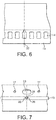
- FIG. 5 -7 An alternative is shown in Figures 5 -7 .
- juxtaposed tang edges are provided with aligned slots 26 into which a plate 27 is inserted.
- the ends 28 of the plate are pre-formed at an angle to the centre, or are folded over to maintain the plate in position.
- adjacent tang sections are formed to overlap, such tang sections comprising an upper tang part 30 as shown in Figure 8 and a lower tang part 31 as shown in Figure 9 .
- an upper tang part is overlapped and combined with a lower tang part to form the joint shown in Figures 3 & 13 . It will be noted that the overlapping joint lies beneath an aperture 14 in the tang.
- the upper tang part 30 includes a hole 32 projecting there-through, the axis of hole 32 being substantially perpendicular to the axis of the tubular section to which the tang part is fixed.
- the lower tang part includes a hole 33 there-through, the axis of which is arranged substantially perpendicular to the axis of the tubular section to which the respective tang part is fixed.
- the holes 32 & 33 become co-axial and combine to form a bore 34.
- the bore 34 extends downwardly from an aperture 14 in the tang and is sized to receive a joint pin 35 to complete the joint.
- a feature of the holes 32 and 33 is that the diameter of hole 32 is larger than that of hole 33.
- the hole 32 may be 4.2 mm in diameter whilst the hole 33 may be 4.0 mm in diameter.
- the bore 34 effectively tapers.
- the joint pin 35 has a lower section 36 of uniform cross section and an upper section 37 which tapers inwardly to the lower section 36.
- the distal end of the lower section is formed with an axial socket 38.
- the pin 35 is sized to be an interference fit within the bore 34, the combination of the reduced diameter of lower hole 33 and the tapered upper section of the pin 35 serving to limit the insertion of the pin 35 into the bore 34.
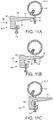
- tool 40 is preferably employed.
- Such a tool has the advantage that significant axial force can be applied to the pin in a very confined space.
- the tool 40 includes a wedge section 41, a base 42, and a deforming device 43.
- the distal end of pin 35 is offered up to the upper entrance of hole 32. Because the lower section 36 of the pin is smaller in diameter than the diameter of hole 32, the pin can be partially inserted into the bore 34.
- the wedge section 41 As the wedge section 41 is introduced into the aperture 14 from which the bore 34 extends, the lower surface 45 of the wedge section contacts the upper end of the pin 35 whilst the upper surface 46 of the wedge section contacts the edge 47 of the aperture that is opposite to the edge containing bore 34.
- the expanding taper of the wedge section 41 causes the pin 35 to be driven into the bore 34 and, thereby, causes the tapered section 35 of the pin to be driven downwardly against the reducing diameter of the bore 34.
- the deforming device comprises a screw having a distal end 50 shaped to locate within socket 38 provided in the end of the pin. As illustrated in Figure 12 , as the screw 43 is would upwardly, the end 50 engages within the socket 38 and deforms the end of the pin outwardly. The end of the pin 35, following deformation, is shown in Figure 13 . When so deformed the pin 35 is restrained against removal from the bore 34 yet, if the rail is to be disassembled, a suitable tool can be readily located within the end of the pin to effect removal.
- the invention provides a method of joining tubular stairlift rail components together that provides positive anchoring against relative rotation between juxtaposed sections, confines the joint components completely within the rail yet allows the rail to be readily formed and disassembled as required.
- juxtaposed tangs are also preferably joined in a manner that will maintain alignment of the tang sections yet allow the rail sections to disassembled at a later date, if necessary.
- FIG. 5 -7 An alternative is shown in Figures 5 -7 .
- juxtaposed tang edges are provided with aligned slots 26 into which a plate 27 is inserted.
- the ends 28 of the plate are pre-formed at an angle to the centre, or are folded over to maintain the plate in position.
- adjacent tang sections may be formed to overlap, such tang sections comprising an upper tang part 30 as shown in Figure 8 and a lower tang part 31 as shown in Figure 9 .
- an upper tang part is overlapped and combined with a lower tang part to form the joint shown in Figures 3 & 13 . It will be noted that the overlapping joint lies beneath an aperture 14 in the tang.
- the upper tang part 30 includes a hole 32 projecting there-through, the axis of hole 32 being substantially perpendicular to the axis of the tubular section to which the tang part is fixed.
- the lower tang part includes a hole 33 there-through, the axis of which is arranged substantially perpendicular to the axis of the tubular section to which the respective tang part is fixed.
- the holes 32 & 33 become co-axial and combine to form a bore 34.
- the bore 34 extends downwardly from an aperture 14 in the tang and is sized to receive a joint pin 35 to complete the joint.
- a feature of the holes 32 and 33 is that the diameter of hole 32 is larger than that of hole 33.
- the hole 32 may be 4.2 mm in diameter whilst the hole 33 may be 4.0 mm in diameter.
- the bore 34 effectively tapers.
- the joint pin 35 has a lower section 36 of uniform cross section and an upper section 37 which tapers inwardly to the lower section 36.
- the distal end of the lower section is formed with an axial socket 38.
- the pin 35 is sized to be an interference fit within the bore 34, the combination of the reduced diameter of lower hole 33 and the tapered upper section of the pin 35 serving to limit the insertion of the pin 35 into the bore 34.
- tool 40 is preferably employed.
- Such a tool has the advantage that significant axial force can be applied to the pin in a very confined space.
- the tool 40 includes a wedge section 41, a base 42, and a deforming device 43.
- the distal end of pin 35 is offered up to the upper entrance of hole 32. Because the lower section 36 of the pin is smaller in diameter than the diameter of hole 32, the pin can be partially inserted into the bore 34.
- the wedge section 41 As the wedge section 41 is introduced into the aperture 14 from which the bore 34 extends, the lower surface 45 of the wedge section contacts the upper end of the pin 35 whilst the upper surface 46 of the wedge section contacts the edge 47 of the aperture that is opposite to the edge containing bore 34.
- the expanding taper of the wedge section 41 causes the pin 35 to be driven into the bore 34 and, thereby, causes the tapered section 35 of the pin to be driven downwardly against the reducing diameter of the bore 34.
- the deforming device comprises a screw having a distal end 50 shaped to locate within socket 38 provided in the end of the pin. As illustrated in Figure 12 , as the screw 43 is would upwardly, the end 50 engages within the socket 38 and deforms the end of the pin outwardly. The end of the pin 35, following deformation, is shown in Figure 13 . When so deformed the pin 35 is restrained against removal from the bore 34 yet, if the rail is to be disassembled, a suitable tool can be readily located within the end of the pin to effect removal.
- the invention provides a method of joining tubular stairlift rail components together that provides positive anchoring against relative rotation between juxtaposed sections, confines the joint components completely within the rail yet allows the rail to be readily formed and disassembled as required.
Landscapes
- Engineering & Computer Science (AREA)
- Mechanical Engineering (AREA)
- General Engineering & Computer Science (AREA)
- Transportation (AREA)
- Automation & Control Theory (AREA)
- Structural Engineering (AREA)
- Mutual Connection Of Rods And Tubes (AREA)
- Escalators And Moving Walkways (AREA)
- Lift-Guide Devices, And Elevator Ropes And Cables (AREA)
Claims (9)
- Verfahren zum Verbinden von rohrförmigen Abschnitten (10, 11) einer Treppenliftschiene, wobei jeder Abschnitt der Schiene einen Dorn (13) aufweist, der von einer äußeren Fläche davon vorsteht, wobei der Dorn mehrere Öffnungen (14) aufweist, die sich entlang des Dorns erstrecken; und wobei die Dorne angrenzender Abschnitte überlappende Bereiche aufweisen (30, 31), wobei jeder der überlappenden Bereiche ein Loch (32, 33) dort hindurch aufweist, sodass, wenn angrenzende Schienenabschnitte miteinander in Eingriff sind, die Löcher koaxial angeordnet sind, um eine Bohrung (34) zu definieren, wobei das Verfahren dadurch gekennzeichnet ist, dass:ein Stift in die Bohrung (35) eingeführt wird, sodass ein distales Ende des Stifts über die Bohrung hinaus vorsteht; unddas distale Ende verformt wird, um ein Entziehen des Stifts (35) aus der Bohrung (34) zu verhindern.
- Verfahren nach Anspruch 1, wobei sich eines der Löcher (32, 33) von einer der Öffnungen (14) erstreckt und wobei das Verfahren das Generieren einer Verschiebekraft zwischen dem Stift (35) und einer Kante (47), die einen Teil der Öffnung definiert, umfasst, um den Stift (35) in die Bohrung (34) zu treiben.
- Verfahren nach Anspruch 2, das das Einführen eines Keils (41) in die eine der Öffnungen (14) zwischen der Kante (47) und dem Stift (35) und das Verschieben des Keils (41), um den Stift (35) in die Bohrung (34) zu treiben, umfasst.
- Verfahren nach Anspruch 3, das das Halten des Stifts (35) in seiner Position mittels des Keils (41) umfasst, während das distale Ende des Stifts (35) verformt wird.
- Verfahren nach Anspruch 3 oder Anspruch 4, das das Verwenden einer Vorrichtung umfasst, die integral mit dem Keil bereitgestellt ist, um die Verformung des distalen Endes des Stifts (35) herbeizuführen.
- Treppenliftschiene, die aus mehreren rohrförmigen Abschnitten (10, 11) gebildet ist, die miteinander verbunden sind, wobei jeder Schienenabschnitt einen Dorn (13) umfasst, der von einer äußeren Fläche davon vorsteht, wobei der Dorn (13) mehrere Öffnungen (14) aufweist, die sich entlang des Dorns (13) erstrecken; wobei die Dorne der angrenzenden Abschnitte überlappende Bereiche (30, 31) aufweisen, wobei jeder der überlappenden Bereiche ein Loch (32, 33) dort hindurch aufweist, sodass, wenn angrenzende Schienenabschnitte miteinander in Eingriff sind, die Löcher auf den Überlappungen koaxial angeordnet sind, um eine Bohrung (34) zu definieren, wobei die Schiene ferner einen Stift (35) umfasst, der in die Bohrung (34) eingeführt wird, um die überlappenden Bereiche miteinander zu verbinden, wobei die Schiene dadurch gekennzeichnet ist, dass:der Stift (35) und/oder die Bohrung (34) dazu konfiguriert und angeordnet sind, dass das Einführen des Stifts in die Bohrung auf eine Endposition beschränkt ist;in der Endposition ein distales Ende des Stifts über die Bohrung hinaus vorsteht; unddas distale Ende verformt ist, um ein Entziehen des Stifts aus der Bohrung zu verhindern.
- Treppenliftschiene nach Anspruch 6, wobei der Stift eine Schräge (37) umfasst.
- Treppenliftschiene nach Anspruch 6 oder Anspruch 7, wobei die Löcher (32, 33) in den überlappenden Bereichen (30, 31) unterschiedliche Durchmesser aufweisen.
- Treppenliftschiene nach einem der Ansprüche 6 bis 8, wobei der Stift (35) eine axiale Aufnahme (38) in dem distalen Ende aufweist.
Applications Claiming Priority (3)
| Application Number | Priority Date | Filing Date | Title |
|---|---|---|---|
| GB1321337.6A GB2520947B (en) | 2013-12-03 | 2013-12-03 | A method and apparatus for forming a stairlift rail from tubular sections |
| EP14803216.2A EP3077319A1 (de) | 2013-12-03 | 2014-11-24 | Verbesserungen an oder in zusammenhang mit treppenaufzügen |
| PCT/GB2014/053458 WO2015082875A1 (en) | 2013-12-03 | 2014-11-24 | Improvements in or relating to stairlifts |
Related Parent Applications (1)
| Application Number | Title | Priority Date | Filing Date |
|---|---|---|---|
| EP14803216.2A Division EP3077319A1 (de) | 2013-12-03 | 2014-11-24 | Verbesserungen an oder in zusammenhang mit treppenaufzügen |
Publications (2)
| Publication Number | Publication Date |
|---|---|
| EP3260407A1 EP3260407A1 (de) | 2017-12-27 |
| EP3260407B1 true EP3260407B1 (de) | 2019-02-20 |
Family
ID=49979733
Family Applications (2)
| Application Number | Title | Priority Date | Filing Date |
|---|---|---|---|
| EP17182069.9A Not-in-force EP3260407B1 (de) | 2013-12-03 | 2014-11-24 | Verbesserungen an oder in zusammenhang mit treppenaufzügen |
| EP14803216.2A Withdrawn EP3077319A1 (de) | 2013-12-03 | 2014-11-24 | Verbesserungen an oder in zusammenhang mit treppenaufzügen |
Family Applications After (1)
| Application Number | Title | Priority Date | Filing Date |
|---|---|---|---|
| EP14803216.2A Withdrawn EP3077319A1 (de) | 2013-12-03 | 2014-11-24 | Verbesserungen an oder in zusammenhang mit treppenaufzügen |
Country Status (5)
| Country | Link |
|---|---|
| US (1) | US10597258B2 (de) |
| EP (2) | EP3260407B1 (de) |
| CN (2) | CN105992746B (de) |
| GB (2) | GB2520947B (de) |
| WO (1) | WO2015082875A1 (de) |
Families Citing this family (4)
| Publication number | Priority date | Publication date | Assignee | Title |
|---|---|---|---|---|
| US10836607B2 (en) * | 2016-04-25 | 2020-11-17 | Stannah Stairlifts Limited | Stairlifts |
| EP3772478A1 (de) * | 2019-08-07 | 2021-02-10 | Interroll Holding AG | Schienenkasten, fördersystem und -verfahren |
| CN111577977A (zh) * | 2020-06-16 | 2020-08-25 | 上海市机械施工集团有限公司 | 管节连接结构 |
| US20240417218A1 (en) * | 2023-03-29 | 2024-12-19 | Leaf Home Safety Solutions | Stair lift systems and methods for assembling, installing, and using such systems |
Family Cites Families (44)
| Publication number | Priority date | Publication date | Assignee | Title |
|---|---|---|---|---|
| FR980584A (fr) * | 1949-02-10 | 1951-05-15 | Raccord pour éléments de construction creux | |
| GB686249A (en) * | 1950-02-17 | 1953-01-21 | Collaro Ltd | Improvements relating to connectors for pipes or tubes |
| FR1175966A (fr) * | 1957-06-12 | 1959-04-03 | Dispositif d'assemblage de tubes pour des contructions diverses | |
| US2997317A (en) * | 1957-11-01 | 1961-08-22 | Dorr Oliver Inc | Coupling device for tubular members having internal wedge means |
| FR1367425A (fr) | 1962-08-23 | 1964-07-24 | Tolerie Ind Et Agricole Du Ct | Procédé d'assemblage et de blocage bout à bout d'éléments tubulaires démontables |
| US3386218A (en) * | 1966-06-08 | 1968-06-04 | Elwin G Smith & Co Inc | Building panel with ribbed sealing element between overlapping edges |
| US3390906A (en) * | 1967-07-31 | 1968-07-02 | Hi Shear Corp | Joint with inherently limited torque level |
| NL7105013A (de) * | 1971-04-15 | 1972-10-17 | ||
| US3883258A (en) * | 1973-05-24 | 1975-05-13 | Kenneth E Hewson | Plastic dowel pin and wood joint assembly |
| US3889315A (en) * | 1974-04-15 | 1975-06-17 | Wilfred Stouffer | Safety door hinge |
| US3966339A (en) * | 1975-02-21 | 1976-06-29 | Borivoj Nemecek | Fasteners |
| FR2414655A1 (fr) * | 1978-01-12 | 1979-08-10 | Routier Equip Sa | Dispositif pour l'assemblage de deux elements tubulaires a profil en section substantiellement ferme |
| FR2428166A1 (fr) * | 1978-06-07 | 1980-01-04 | Gioan Alain | Dispositif de raccordement et de fixation pour tubes rigides |
| FR2468022A1 (fr) * | 1979-10-19 | 1981-04-30 | Peugeot Cycles | Dispositif de raccordement demontable de tubes |
| FR2558218B1 (fr) * | 1984-01-12 | 1987-05-07 | Fabrications Indles Et | Noyau de jonction pour trancons de tube devant etre assembles sans jeu |
| FR2570136B1 (fr) * | 1984-09-10 | 1988-04-29 | Franceschini Bernard | Dispositif d'aboutage et de fixation de deux elements tubulaires l'un a l'autre et ossature porteuse comportant de tels dispositifs |
| US4840390A (en) * | 1986-09-30 | 1989-06-20 | Invacare Corporation | Symmetrically modular wheelchair |
| US4767232A (en) * | 1987-05-07 | 1988-08-30 | Superior Aluminum Products, Inc. | Hinge joint for tubular rail and post members |
| US4932807A (en) * | 1988-07-28 | 1990-06-12 | The United States Of America As Represented By The Administrator Of The National Aeronautics And Space Administration | Clevis joint for deployable space structures |
| US5083883A (en) * | 1989-04-26 | 1992-01-28 | The United States Of America As Represented By The Secretary Of The Army | Lockable pushbutton pin coupler |
| US5105741A (en) * | 1990-10-12 | 1992-04-21 | Duane Leary | Portable equipment handling apparatus |
| US5078534A (en) * | 1990-12-19 | 1992-01-07 | Samson Truss Corporation | Flush nut connectors |
| US5255993A (en) * | 1992-05-08 | 1993-10-26 | U.S. Government Represented By The Secretary Of The Army | Push button coupler |
| NL1001932C2 (en) * | 1994-12-23 | 1996-09-11 | Ooms Otto Bv | Chair lift installed on staircase - has chair guides detachable from holders on staircase |
| NL9402200A (nl) * | 1994-12-23 | 1996-08-01 | Ooms Otto Bv | Liftsamenstel en een werkwijze voor het aanbrengen van een railsysteem. |
| US5720144A (en) * | 1996-03-07 | 1998-02-24 | Knudson; Gary A. | Metal beams with thermal break and methods |
| US5938274A (en) * | 1997-11-14 | 1999-08-17 | Wabash National Corporation | Coining offset into edge of composite plate members for forming trailer doors and walls |
| US6676326B2 (en) * | 2001-06-25 | 2004-01-13 | Wen-Chang Wu | Square lamp post insertional conjoinment structure |
| US20030164488A1 (en) * | 2002-03-01 | 2003-09-04 | Terrels Christopher J. | Handrail connection |
| WO2004070152A2 (en) * | 2003-01-27 | 2004-08-19 | Hopper Joel S | Durable horse fence |
| CN2721590Y (zh) * | 2003-06-01 | 2005-08-31 | 陈尚理 | 住宅楼楼梯间升降机组 |
| DE112004000954B4 (de) * | 2003-06-04 | 2011-12-29 | Kokuyo Co., Ltd. | Bauteilkopplungsvorrichtung und Tisch mit dieser Bauteilkopplungsvorrichtung |
| US7641180B2 (en) * | 2003-09-19 | 2010-01-05 | BALU PTY Ltd. | Handrail or top rail, post and panel assembly and connector therefor |
| US7143988B2 (en) * | 2004-06-10 | 2006-12-05 | Diani, Llc. | Apparatus and method for mounting a fixture |
| US8157056B2 (en) * | 2005-01-20 | 2012-04-17 | Feldhaus Daniel E | Coupler for ladder standoff arrangement |
| NL1030131C2 (nl) * | 2005-10-06 | 2007-04-10 | Free Lift B V | Hellinglifteenheid, alsmede hellinglift. |
| US8371768B1 (en) * | 2011-01-21 | 2013-02-12 | Alupro Enterprise Co., Ltd. | Connectin unit for tubes |
| CN202245629U (zh) | 2011-09-08 | 2012-05-30 | 幸福树电机股份有限公司 | 轨道式运送装置 |
| US20130236237A1 (en) * | 2012-03-08 | 2013-09-12 | Mark A. Schmidt | Telescopic hot stick with button capture feature |
| FR2995294A1 (fr) * | 2012-09-11 | 2014-03-14 | Jean-Damien Duval | Dispositif de jonction d'elements tubulaires notamment pour la fabrication de rampes |
| DE102013009564A1 (de) * | 2013-06-06 | 2014-12-11 | Liebherr-Werk Biberach Gmbh | Vorrichtung zum Verbinden von Profilelementen |
| GB2519100A (en) * | 2013-10-09 | 2015-04-15 | Island Mobility Ltd | Stairlift component and kit |
| NL2013085B1 (en) * | 2014-06-27 | 2016-07-11 | Handicare Stairlifts B V | Stairlift. |
| US10258524B2 (en) * | 2016-02-22 | 2019-04-16 | Nexxspan Healthcare, Llc | Transfer system with sacrificial mechanical link |
-
2013
- 2013-12-03 GB GB1321337.6A patent/GB2520947B/en not_active Expired - Fee Related
- 2013-12-03 GB GB1801057.9A patent/GB2559054B/en active Active
-
2014
- 2014-11-24 US US15/101,070 patent/US10597258B2/en not_active Expired - Fee Related
- 2014-11-24 CN CN201480074788.9A patent/CN105992746B/zh not_active Expired - Fee Related
- 2014-11-24 CN CN201910001329.2A patent/CN109775521A/zh active Pending
- 2014-11-24 WO PCT/GB2014/053458 patent/WO2015082875A1/en not_active Ceased
- 2014-11-24 EP EP17182069.9A patent/EP3260407B1/de not_active Not-in-force
- 2014-11-24 EP EP14803216.2A patent/EP3077319A1/de not_active Withdrawn
Also Published As
| Publication number | Publication date |
|---|---|
| US10597258B2 (en) | 2020-03-24 |
| EP3077319A1 (de) | 2016-10-12 |
| CN105992746B (zh) | 2019-01-25 |
| GB201801057D0 (en) | 2018-03-07 |
| GB2520947B (en) | 2018-09-05 |
| GB2559054A (en) | 2018-07-25 |
| WO2015082875A1 (en) | 2015-06-11 |
| CN105992746A (zh) | 2016-10-05 |
| CN109775521A (zh) | 2019-05-21 |
| EP3260407A1 (de) | 2017-12-27 |
| GB2520947A (en) | 2015-06-10 |
| GB2559054B (en) | 2018-09-05 |
| US20160304318A1 (en) | 2016-10-20 |
| GB201321337D0 (en) | 2014-01-15 |
Similar Documents
| Publication | Publication Date | Title |
|---|---|---|
| EP3260407B1 (de) | Verbesserungen an oder in zusammenhang mit treppenaufzügen | |
| US3522933A (en) | Railing formed of interlocking components | |
| EP3141672B1 (de) | Koppler für spiralförmigen bewehrungsstab | |
| JP6875084B2 (ja) | 機械要素用の締結システム | |
| US20130212861A1 (en) | Method and Device for Locking a Support Ring to a Scaffolding Column | |
| EP2478230B1 (de) | System und verfahren für die starre verbindung von tafeln | |
| KR101208677B1 (ko) | 프리 캐스트 콘크리트용 커플러 및 이를 구비한 프리 캐스트 콘크리트 조립체 | |
| JP3135948U (ja) | 鋼管杭の継合構造 | |
| CA2638086C (en) | Method and apparatus for attaching flange portions to ducts | |
| JP6601299B2 (ja) | 鋼管杭の継手構造及び連結鋼管杭 | |
| JP7047375B2 (ja) | 柱の接合方法、それに用いるボルト保持具及び鋼管柱 | |
| JP6242381B2 (ja) | 固定金具 | |
| KR101066305B1 (ko) | 냉간성형강 부재의 연결부 구조 및 연결방법 | |
| TWI743306B (zh) | 緊固構造 | |
| JP6387428B2 (ja) | 締結構造および締結方法 | |
| JP2021031897A (ja) | 貫通孔位置合わせ治具、及び貫通孔位置合わせ方法 | |
| JP2004293035A (ja) | 鋼管の継手構造 | |
| JP2006077482A (ja) | 鋼管杭構造 | |
| KR101982210B1 (ko) | 압연기용 유니버셜 조인트와 이를 구비한 나사 철근용 압연기 | |
| JP5991622B2 (ja) | 杭の無溶接継手 | |
| JP4347149B2 (ja) | 緩み防止手段を備えた杭の縦継ぎ装置の機械継手 | |
| KR101616543B1 (ko) | 마감재 지지앵커 시공장치, 마감재 지지앵커 시공방법 및 마감재 지지앵커 | |
| JP7841701B2 (ja) | 固定金具および接合方法 | |
| EP1923588A1 (de) | Balgkupplung | |
| JP3947724B2 (ja) | 防護柵における鋼矢板の固定方法及び鋼矢板の固定具 |
Legal Events
| Date | Code | Title | Description |
|---|---|---|---|
| PUAI | Public reference made under article 153(3) epc to a published international application that has entered the european phase |
Free format text: ORIGINAL CODE: 0009012 |
|
| STAA | Information on the status of an ep patent application or granted ep patent |
Free format text: STATUS: THE APPLICATION HAS BEEN PUBLISHED |
|
| AC | Divisional application: reference to earlier application |
Ref document number: 3077319 Country of ref document: EP Kind code of ref document: P |
|
| AK | Designated contracting states |
Kind code of ref document: A1 Designated state(s): AL AT BE BG CH CY CZ DE DK EE ES FI FR GB GR HR HU IE IS IT LI LT LU LV MC MK MT NL NO PL PT RO RS SE SI SK SM TR |
|
| STAA | Information on the status of an ep patent application or granted ep patent |
Free format text: STATUS: REQUEST FOR EXAMINATION WAS MADE |
|
| 17P | Request for examination filed |
Effective date: 20180626 |
|
| RBV | Designated contracting states (corrected) |
Designated state(s): AL AT BE BG CH CY CZ DE DK EE ES FI FR GB GR HR HU IE IS IT LI LT LU LV MC MK MT NL NO PL PT RO RS SE SI SK SM TR |
|
| RIC1 | Information provided on ipc code assigned before grant |
Ipc: B66B 9/08 20060101AFI20180724BHEP Ipc: F16B 7/04 20060101ALI20180724BHEP |
|
| GRAP | Despatch of communication of intention to grant a patent |
Free format text: ORIGINAL CODE: EPIDOSNIGR1 |
|
| STAA | Information on the status of an ep patent application or granted ep patent |
Free format text: STATUS: GRANT OF PATENT IS INTENDED |
|
| INTG | Intention to grant announced |
Effective date: 20180919 |
|
| GRAS | Grant fee paid |
Free format text: ORIGINAL CODE: EPIDOSNIGR3 |
|
| GRAA | (expected) grant |
Free format text: ORIGINAL CODE: 0009210 |
|
| STAA | Information on the status of an ep patent application or granted ep patent |
Free format text: STATUS: THE PATENT HAS BEEN GRANTED |
|
| AC | Divisional application: reference to earlier application |
Ref document number: 3077319 Country of ref document: EP Kind code of ref document: P |
|
| AK | Designated contracting states |
Kind code of ref document: B1 Designated state(s): AL AT BE BG CH CY CZ DE DK EE ES FI FR GB GR HR HU IE IS IT LI LT LU LV MC MK MT NL NO PL PT RO RS SE SI SK SM TR |
|
| REG | Reference to a national code |
Ref country code: GB Ref legal event code: FG4D |
|
| REG | Reference to a national code |
Ref country code: CH Ref legal event code: EP |
|
| REG | Reference to a national code |
Ref country code: AT Ref legal event code: REF Ref document number: 1097889 Country of ref document: AT Kind code of ref document: T Effective date: 20190315 |
|
| REG | Reference to a national code |
Ref country code: IE Ref legal event code: FG4D |
|
| REG | Reference to a national code |
Ref country code: DE Ref legal event code: R096 Ref document number: 602014041638 Country of ref document: DE |
|
| REG | Reference to a national code |
Ref country code: NL Ref legal event code: FP |
|
| REG | Reference to a national code |
Ref country code: LT Ref legal event code: MG4D |
|
| PG25 | Lapsed in a contracting state [announced via postgrant information from national office to epo] |
Ref country code: NO Free format text: LAPSE BECAUSE OF FAILURE TO SUBMIT A TRANSLATION OF THE DESCRIPTION OR TO PAY THE FEE WITHIN THE PRESCRIBED TIME-LIMIT Effective date: 20190520 Ref country code: PT Free format text: LAPSE BECAUSE OF FAILURE TO SUBMIT A TRANSLATION OF THE DESCRIPTION OR TO PAY THE FEE WITHIN THE PRESCRIBED TIME-LIMIT Effective date: 20190620 Ref country code: SE Free format text: LAPSE BECAUSE OF FAILURE TO SUBMIT A TRANSLATION OF THE DESCRIPTION OR TO PAY THE FEE WITHIN THE PRESCRIBED TIME-LIMIT Effective date: 20190220 Ref country code: FI Free format text: LAPSE BECAUSE OF FAILURE TO SUBMIT A TRANSLATION OF THE DESCRIPTION OR TO PAY THE FEE WITHIN THE PRESCRIBED TIME-LIMIT Effective date: 20190220 Ref country code: LT Free format text: LAPSE BECAUSE OF FAILURE TO SUBMIT A TRANSLATION OF THE DESCRIPTION OR TO PAY THE FEE WITHIN THE PRESCRIBED TIME-LIMIT Effective date: 20190220 |
|
| PG25 | Lapsed in a contracting state [announced via postgrant information from national office to epo] |
Ref country code: LV Free format text: LAPSE BECAUSE OF FAILURE TO SUBMIT A TRANSLATION OF THE DESCRIPTION OR TO PAY THE FEE WITHIN THE PRESCRIBED TIME-LIMIT Effective date: 20190220 Ref country code: IS Free format text: LAPSE BECAUSE OF FAILURE TO SUBMIT A TRANSLATION OF THE DESCRIPTION OR TO PAY THE FEE WITHIN THE PRESCRIBED TIME-LIMIT Effective date: 20190620 Ref country code: RS Free format text: LAPSE BECAUSE OF FAILURE TO SUBMIT A TRANSLATION OF THE DESCRIPTION OR TO PAY THE FEE WITHIN THE PRESCRIBED TIME-LIMIT Effective date: 20190220 Ref country code: BG Free format text: LAPSE BECAUSE OF FAILURE TO SUBMIT A TRANSLATION OF THE DESCRIPTION OR TO PAY THE FEE WITHIN THE PRESCRIBED TIME-LIMIT Effective date: 20190520 Ref country code: GR Free format text: LAPSE BECAUSE OF FAILURE TO SUBMIT A TRANSLATION OF THE DESCRIPTION OR TO PAY THE FEE WITHIN THE PRESCRIBED TIME-LIMIT Effective date: 20190521 Ref country code: HR Free format text: LAPSE BECAUSE OF FAILURE TO SUBMIT A TRANSLATION OF THE DESCRIPTION OR TO PAY THE FEE WITHIN THE PRESCRIBED TIME-LIMIT Effective date: 20190220 |
|
| REG | Reference to a national code |
Ref country code: AT Ref legal event code: MK05 Ref document number: 1097889 Country of ref document: AT Kind code of ref document: T Effective date: 20190220 |
|
| PG25 | Lapsed in a contracting state [announced via postgrant information from national office to epo] |
Ref country code: ES Free format text: LAPSE BECAUSE OF FAILURE TO SUBMIT A TRANSLATION OF THE DESCRIPTION OR TO PAY THE FEE WITHIN THE PRESCRIBED TIME-LIMIT Effective date: 20190220 Ref country code: DK Free format text: LAPSE BECAUSE OF FAILURE TO SUBMIT A TRANSLATION OF THE DESCRIPTION OR TO PAY THE FEE WITHIN THE PRESCRIBED TIME-LIMIT Effective date: 20190220 Ref country code: AL Free format text: LAPSE BECAUSE OF FAILURE TO SUBMIT A TRANSLATION OF THE DESCRIPTION OR TO PAY THE FEE WITHIN THE PRESCRIBED TIME-LIMIT Effective date: 20190220 Ref country code: SK Free format text: LAPSE BECAUSE OF FAILURE TO SUBMIT A TRANSLATION OF THE DESCRIPTION OR TO PAY THE FEE WITHIN THE PRESCRIBED TIME-LIMIT Effective date: 20190220 Ref country code: EE Free format text: LAPSE BECAUSE OF FAILURE TO SUBMIT A TRANSLATION OF THE DESCRIPTION OR TO PAY THE FEE WITHIN THE PRESCRIBED TIME-LIMIT Effective date: 20190220 Ref country code: CZ Free format text: LAPSE BECAUSE OF FAILURE TO SUBMIT A TRANSLATION OF THE DESCRIPTION OR TO PAY THE FEE WITHIN THE PRESCRIBED TIME-LIMIT Effective date: 20190220 |
|
| REG | Reference to a national code |
Ref country code: DE Ref legal event code: R097 Ref document number: 602014041638 Country of ref document: DE |
|
| PG25 | Lapsed in a contracting state [announced via postgrant information from national office to epo] |
Ref country code: SM Free format text: LAPSE BECAUSE OF FAILURE TO SUBMIT A TRANSLATION OF THE DESCRIPTION OR TO PAY THE FEE WITHIN THE PRESCRIBED TIME-LIMIT Effective date: 20190220 Ref country code: PL Free format text: LAPSE BECAUSE OF FAILURE TO SUBMIT A TRANSLATION OF THE DESCRIPTION OR TO PAY THE FEE WITHIN THE PRESCRIBED TIME-LIMIT Effective date: 20190220 |
|
| PLBE | No opposition filed within time limit |
Free format text: ORIGINAL CODE: 0009261 |
|
| STAA | Information on the status of an ep patent application or granted ep patent |
Free format text: STATUS: NO OPPOSITION FILED WITHIN TIME LIMIT |
|
| PG25 | Lapsed in a contracting state [announced via postgrant information from national office to epo] |
Ref country code: AT Free format text: LAPSE BECAUSE OF FAILURE TO SUBMIT A TRANSLATION OF THE DESCRIPTION OR TO PAY THE FEE WITHIN THE PRESCRIBED TIME-LIMIT Effective date: 20190220 |
|
| 26N | No opposition filed |
Effective date: 20191121 |
|
| PGFP | Annual fee paid to national office [announced via postgrant information from national office to epo] |
Ref country code: NL Payment date: 20191120 Year of fee payment: 6 Ref country code: DE Payment date: 20191121 Year of fee payment: 6 |
|
| PG25 | Lapsed in a contracting state [announced via postgrant information from national office to epo] |
Ref country code: SI Free format text: LAPSE BECAUSE OF FAILURE TO SUBMIT A TRANSLATION OF THE DESCRIPTION OR TO PAY THE FEE WITHIN THE PRESCRIBED TIME-LIMIT Effective date: 20190220 |
|
| PGFP | Annual fee paid to national office [announced via postgrant information from national office to epo] |
Ref country code: IT Payment date: 20191126 Year of fee payment: 6 Ref country code: FR Payment date: 20191120 Year of fee payment: 6 |
|
| PG25 | Lapsed in a contracting state [announced via postgrant information from national office to epo] |
Ref country code: TR Free format text: LAPSE BECAUSE OF FAILURE TO SUBMIT A TRANSLATION OF THE DESCRIPTION OR TO PAY THE FEE WITHIN THE PRESCRIBED TIME-LIMIT Effective date: 20190220 |
|
| REG | Reference to a national code |
Ref country code: CH Ref legal event code: PL |
|
| PG25 | Lapsed in a contracting state [announced via postgrant information from national office to epo] |
Ref country code: LI Free format text: LAPSE BECAUSE OF NON-PAYMENT OF DUE FEES Effective date: 20191130 Ref country code: LU Free format text: LAPSE BECAUSE OF NON-PAYMENT OF DUE FEES Effective date: 20191124 Ref country code: CH Free format text: LAPSE BECAUSE OF NON-PAYMENT OF DUE FEES Effective date: 20191130 Ref country code: MC Free format text: LAPSE BECAUSE OF FAILURE TO SUBMIT A TRANSLATION OF THE DESCRIPTION OR TO PAY THE FEE WITHIN THE PRESCRIBED TIME-LIMIT Effective date: 20190220 |
|
| REG | Reference to a national code |
Ref country code: BE Ref legal event code: MM Effective date: 20191130 |
|
| PG25 | Lapsed in a contracting state [announced via postgrant information from national office to epo] |
Ref country code: IE Free format text: LAPSE BECAUSE OF NON-PAYMENT OF DUE FEES Effective date: 20191124 |
|
| PG25 | Lapsed in a contracting state [announced via postgrant information from national office to epo] |
Ref country code: BE Free format text: LAPSE BECAUSE OF NON-PAYMENT OF DUE FEES Effective date: 20191130 |
|
| PG25 | Lapsed in a contracting state [announced via postgrant information from national office to epo] |
Ref country code: RO Free format text: LAPSE BECAUSE OF FAILURE TO SUBMIT A TRANSLATION OF THE DESCRIPTION OR TO PAY THE FEE WITHIN THE PRESCRIBED TIME-LIMIT Effective date: 20190220 |
|
| PG25 | Lapsed in a contracting state [announced via postgrant information from national office to epo] |
Ref country code: CY Free format text: LAPSE BECAUSE OF FAILURE TO SUBMIT A TRANSLATION OF THE DESCRIPTION OR TO PAY THE FEE WITHIN THE PRESCRIBED TIME-LIMIT Effective date: 20190220 |
|
| REG | Reference to a national code |
Ref country code: DE Ref legal event code: R119 Ref document number: 602014041638 Country of ref document: DE |
|
| REG | Reference to a national code |
Ref country code: NL Ref legal event code: MM Effective date: 20201201 |
|
| PG25 | Lapsed in a contracting state [announced via postgrant information from national office to epo] |
Ref country code: HU Free format text: LAPSE BECAUSE OF FAILURE TO SUBMIT A TRANSLATION OF THE DESCRIPTION OR TO PAY THE FEE WITHIN THE PRESCRIBED TIME-LIMIT; INVALID AB INITIO Effective date: 20141124 Ref country code: MT Free format text: LAPSE BECAUSE OF FAILURE TO SUBMIT A TRANSLATION OF THE DESCRIPTION OR TO PAY THE FEE WITHIN THE PRESCRIBED TIME-LIMIT Effective date: 20190220 |
|
| PG25 | Lapsed in a contracting state [announced via postgrant information from national office to epo] |
Ref country code: NL Free format text: LAPSE BECAUSE OF NON-PAYMENT OF DUE FEES Effective date: 20201201 |
|
| PG25 | Lapsed in a contracting state [announced via postgrant information from national office to epo] |
Ref country code: IT Free format text: LAPSE BECAUSE OF NON-PAYMENT OF DUE FEES Effective date: 20201124 Ref country code: FR Free format text: LAPSE BECAUSE OF NON-PAYMENT OF DUE FEES Effective date: 20201130 |
|
| PG25 | Lapsed in a contracting state [announced via postgrant information from national office to epo] |
Ref country code: DE Free format text: LAPSE BECAUSE OF NON-PAYMENT OF DUE FEES Effective date: 20210601 |
|
| PGFP | Annual fee paid to national office [announced via postgrant information from national office to epo] |
Ref country code: GB Payment date: 20211022 Year of fee payment: 8 |
|
| PG25 | Lapsed in a contracting state [announced via postgrant information from national office to epo] |
Ref country code: MK Free format text: LAPSE BECAUSE OF FAILURE TO SUBMIT A TRANSLATION OF THE DESCRIPTION OR TO PAY THE FEE WITHIN THE PRESCRIBED TIME-LIMIT Effective date: 20190220 |
|
| P01 | Opt-out of the competence of the unified patent court (upc) registered |
Effective date: 20230523 |
|
| GBPC | Gb: european patent ceased through non-payment of renewal fee |
Effective date: 20221124 |
|
| PG25 | Lapsed in a contracting state [announced via postgrant information from national office to epo] |
Ref country code: GB Free format text: LAPSE BECAUSE OF NON-PAYMENT OF DUE FEES Effective date: 20221124 |