EP3260600B1 - Verfahren zum reparieren einer eisenbahnschiene mithilfe einer reparaturform - Google Patents
Verfahren zum reparieren einer eisenbahnschiene mithilfe einer reparaturform Download PDFInfo
- Publication number
- EP3260600B1 EP3260600B1 EP17171995.8A EP17171995A EP3260600B1 EP 3260600 B1 EP3260600 B1 EP 3260600B1 EP 17171995 A EP17171995 A EP 17171995A EP 3260600 B1 EP3260600 B1 EP 3260600B1
- Authority
- EP
- European Patent Office
- Prior art keywords
- recess
- rail
- circulation rail
- circulation
- withdrawing
- Prior art date
- Legal status (The legal status is an assumption and is not a legal conclusion. Google has not performed a legal analysis and makes no representation as to the accuracy of the status listed.)
- Active
Links
Images


Classifications
-
- E—FIXED CONSTRUCTIONS
- E01—CONSTRUCTION OF ROADS, RAILWAYS, OR BRIDGES
- E01B—PERMANENT WAY; PERMANENT-WAY TOOLS; MACHINES FOR MAKING RAILWAYS OF ALL KINDS
- E01B31/00—Working rails, sleepers, baseplates, or the like, in or on the line; Machines, tools, or auxiliary devices specially designed therefor
- E01B31/02—Working rail or other metal track components on the spot
- E01B31/18—Reconditioning or repairing worn or damaged parts on the spot, e.g. applying inlays, building-up rails by welding; Heating or cooling of parts on the spot, e.g. for reducing joint gaps, for hardening rails
Definitions
- the present invention relates to the field of repairing a rail of a railway.
- a railway conventionally comprises longitudinal traffic rails connected by transverse sleepers of wood or concrete which rest on the ground.
- two consecutive circulation rails are connected by solder joints.
- a joint has the disadvantage of creating a discontinuity between the circulation rails, which is a source of shock and prematurely increases the wear of the circulation rails.
- LRS Long Rail Welded
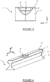
- a circulation rail 1 comprises: a lower part 13, designated “pad”, adapted to rest on the ground, an upper part 11, designated “mushroom”, adapted to be in contact with a wheel of a rail vehicle according to a upper surface 14 designated “tread”, and an intermediate portion 12, designated “soul” which connects the upper portion 11 to the lower portion 13.
- a rail 1 is known to those skilled in the art and will not be presented in more detail.
- the circulation rail 1 extends longitudinally along an axis X, laterally along an axis Y and vertically along an axis Z so as to form an orthogonal reference (X, Y, Z).
- the mushroom 11 of a traffic rail 1 may comprise a damaged zone ZE (impacting or not the tread 14), which affects its behavior.
- the repair method depends on the size of the damaged area.
- the damaged zone ZE is of large size, greater than a threshold limit of keeping track known to those skilled in the art
- the damaged portion of the circulation rail is removed and replaced by a new longitudinal portion known to the man of the trade under the designation "coupon".
- the new longitudinal portion must be welded to the existing longitudinal portions of an LRS rail, which increases the number of solder joints and has the aforementioned drawbacks. The performance of the rail LRS are then degraded.
- this repair method proposes to remove a damaged zone ZE located at the mushroom 11 of the circulation rail 1 (impacting or not the tread 14) by producing a recess 2, 3 in the circulation rail 1. Then, a mold (not shown) is placed around the recess 2, 3 to allow the casting of liquid metal in the mold and, consequently, the filling of the recess 2, 3. The damaged zone ZE of the mushroom 11 of the circulation rail 1 is thus replaced by a defect free zone formed from the cast metal.
- the circulation rail 1 comprises a "dressing" made from the cast metal.
- the recess 2, 3 made in the mushroom 11 of the circulation rail 1 is in the form of a notch that can be of different sizes and shapes.
- the notch may be of circular shape 2 or rectangular 3.
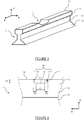
- a notch is called "circular" when the profile of the recess 2, 3 in the longitudinal plane of the circulation rail 1, that is to say, the plane (X, Z) has a shape of an arc of a circle.
- the circular notch 2 is obtained by cutting metal (local oxidation) by means of a template for a circular cut. Such cutting is accurate but its length is limited to 90 mm, which has a first disadvantage.
- a circular notch 2 does not allow the removal of a damaged area which is deep. Indeed, as illustrated in figure 2 , the vertical distance P2 between the tread 14 and the bottom of the circular notch 2 is variable along the length of the notch 2, which does not remove a damaged zone ZE of great length in the depth of the mushroom 11. In other words, the notch length is variable at a given depth.
- a notch 3 is called "rectangular" when the profile of the recess 3 in the longitudinal plane of the circulation rail 1, that is to say, the plane (X, Z), consecutively presents a vertical flank 31, a flank horizontal 32 and a vertical flank 33.
- a rectangular notch 3 has a maximum length of 55 mm, which limits its application.
- a rectangular notch 3 is obtained by grinding, which takes time and increases the cost of repair.
- grinding defects may occur at the intersection of the flanks.
- the patent application GB802256 has such a rectangular notch.
- liquid metal M at a very high temperature is poured into the rectangular notch 3, resulting in the appearance of a melting zone ZF in the mushroom 11 at the level of the profile. the rectangular notch 3.
- a melting zone ZF also called molten zone, allows the liquid metal M added in the rectangular notch 3 to mingle with the existing metal of the circulation rail 1 in order to form a weld of good quality.
- the melted zone ZF must be as large as possible in order to ensure the good behavior of the weld.
- the melted zone ZF is not of constant width and is, in particular, thinner near the ends of the horizontal flank 32 of the profile of the rectangular notch 3, which can affect the robustness in the time of such a weld.
- EP 2,808,446 A1 and FR 2,266,570 also relate to the repair of a rail of a railway.
- One of the objectives of the present invention is to propose a new repair method that makes it possible to overcome the aforementioned drawbacks while being simple to implement.
- the invention is remarkable in that said recess has, in a plane in longitudinal section (X, Z), a concave profile successively comprising a first curvilinear portion, a longitudinal portion and a second curvilinear portion.
- the curvilinear portions make it possible to obtain a wide melting zone when filling the mold with liquid metal, which guarantees a robust weld over time.
- the melting zone has a width of at least 3 mm.
- the recess has a depth configured to maintain a residual thickness of the upper portion of the rail between 6 and 10 mm.
- the depth is adapted to the profile of the circulation rail.
- the recess has a total length of between 126 and 140 mm, preferably of the order of 130 mm.
- the total length is defined at the upper surface, i.e., of the tread.
- Such a recess is adapted to remove a damaged area of great depth, which avoids replacing a damaged portion of the rail with a new portion.
- the length of the longitudinal portion of the recess is between 50 mm and 80 mm.
- Such a recess allows to remove a damaged area which is lengthened in depth in the manner of a rectangular notch.
- the radius of curvature of each curvilinear portion of the recess is between 40 mm and 44 mm, preferably of the order of 42 mm.
- the melted zone has a large thickness.
- At least one curvilinear portion is a portion of arc of a circle of constant radius of curvature.
- a curvilinear portion makes it possible to form a molten zone of large and regular thickness along the curvilinear portion, which improves the robustness.
- each curvilinear portion is a portion of a circular arc of constant radius of curvature.
- the radii of curvature of the curvilinear portions are equal.
- the step of removing the damaged zone comprises at least one step of removal by means of a template, preferably by oxycutting.
- a withdrawal is analogous to a withdrawal for a circular notch.
- the skilled person can achieve such withdrawal quickly and accurately.
- the recess is symmetrical with respect to a plane transverse to the axis along which the circulation rail extends.
- the circulation rail is repaired homogeneously, which improves the strength of the weld.
- the removal step makes it possible to make the curvilinear portions similarly to a circular notch.
- the template according to the prior art can be preserved.
- the first two withdrawal phases are carried out by flame cutting and then grinding again.
- the third withdrawal phase is performed by grinding.
- the recess has a homogeneous surface state.
- the same template is used to form the two curvilinear portions successively.
- a single template makes it possible to form the recess in a single withdrawal step.
- the invention also relates to a mold for repairing a rail of a railway track, the mold comprising an intermediate portion adapted to be positioned at an upper portion of the circulation rail which is adapted to be in contact with a wheel of a railway vehicle, the intermediate portion comprising at least one cavity having a concave profile successively comprising a first curvilinear portion, a longitudinal portion and a second curvilinear portion.
- Such a mold is adapted to guide liquid metal in a recess as presented above to obtain a quality repair.
- This application also describes a running rail extending longitudinally along an axis X and vertically along an axis Z, said circulation rail comprising an upper part adapted to be in contact with a wheel of a railway vehicle, the upper part comprising at least one minus a new zone formed by filling with liquid metal of a recess of said upper part, said recess having, in a plane in longitudinal section (X, Z), a concave profile successively comprising a first curvilinear portion, a longitudinal portion and a second curvilinear portion.
- a circulation rail 1 comprises: a lower part 13, designated “pad”, adapted to rest on the ground, an upper part 11, designated “mushroom”, adapted to be in contact with a wheel of a rail vehicle according to a upper surface 14 designated “tread”, and an intermediate portion 12, designated “soul” which connects the upper part 11 to the part 13.
- a circulation rail 1 is known to those skilled in the art and will not be presented in more detail.
- the circulation rail 1 extends longitudinally along an axis X, laterally along an axis Y and vertically along an axis Z so as to form an orthogonal reference (X, Y, Z).
- the circulation rail 1 comprises at least one damaged zone ZE formed in its upper part 11.
- a damaged zone ZE corresponds to a rail portion whose upper portion 11 contains at least one defect (affecting or not the tread 14) whose dimensions can reach or exceed a value known as "threshold limit of maintenance track" known from the skilled person.
- the "limit threshold for keeping track” corresponds to a damaged zone ZE whose length is 80 mm and / or the depth is 15 mm.
- the defects of a damaged zone ZE can be in various forms, in particular a slump and / or widening of the tread 14, localized impacts, horizontal cracks or diving cracks propagating in the depth of a circulation rail 1.
- the repair method comprises a step of removing the damaged zone ZE so as to form a recess 4 in the upper part 11 of the circulation rail 1.
- said recess 4 has, in a plane in longitudinal section (X, Z), a concave profile 40 successively comprising a first curvilinear portion 41, a longitudinal portion 42 and a second curvilinear portion 43.
- a recess can be considered an "oblong" notch.
- the longitudinal portion 42 extends horizontally, that is to say, parallel to the tread 14.
- the recess 4 has a total length L1 of between 126 and 140 mm, preferably of the order of 130 mm.
- the length L2 of the longitudinal portion 42 of the recess 4 is between 50 and 80 mm.
- the ratio of the length of the longitudinal portion 42 to the total length L1 is between 36% and 64% so as to allow removal of a damaged zone ZE of considerable length in depth of the circulation rail 1 in the manner of a rectangular notch.
- the recess 4 has a depth P1 configured to maintain a residual thickness of the upper part of the rail between 6 and 10 mm.
- each curvilinear portion 41, 43 of the recess 4 is between 40 and 44 mm, preferably of the order of 42 mm.
- the radii of curvature of the curvilinear portions are equal so that the recess has a plane of symmetry.
- Each curvilinear portion 41, 43 corresponds to a portion of a circular arc of constant radius of curvature. Nevertheless, the invention also applies to curvilinear portions having different radii of curvature and different angular ranges in order to be able to adapt to damaged zones ZE of different shapes.
- the withdrawal phases using a template 61, 62 are performed by an oxycutting method known to those skilled in the art in order to obtain a precise and rapid withdrawal.
- the removal of the material between the oxycutting cut areas is preferably carried out by grinding in order to directly guarantee a surface condition free of impurities related to the cutting method.
- the curvilinear portions 41, 43 may also be resumed by grinding.
- the recess 4 is conveniently formed similarly to a circular notch according to the prior art.
- the mushroom 11 of the circulation rail 1 advantageously comprises at least a residual height h of 8 mm, preferably between 6 and 10 mm, in order to allow the formation of a large width melted zone to obtain an optimum weld as will be presented later.
- one and the same template is used successively to produce the two curvilinear portions 41, 43.
- a single template of suitable shape can be used to remove the entire damaged area, which accelerates the removal step.
- the template has an oblong profile.
- the method further comprises a step of placing a mold 5 around the recess 4.
- the general structure of such a mold 5 is known to those skilled in the art.
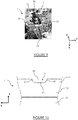
- the mold 5 has an internal cavity 50 adapted to follow the curvature of said circulation rail 1 and ensure its sealing during the flow of the liquid metal. As illustrated in figure 9 , the mold 5 has an upper opening 56 allowing access to said internal cavity 50.
- the mold 5 comprises a lower portion 52, adapted to be positioned at the core 12 of the circulation rail 1, an upper portion 53, adapted to be positioned above the upper surface 14 of the circulation rail 1 and an intermediate portion 54 adapted to be positioned at the level of the mushroom 11 to form a lateral envelope to the recess 4.
- the intermediate portion 54 of the mold 5 comprises at least one recess 7 having a concave profile 70 successively comprising a first curvilinear portion 71, a longitudinal portion 72 and a second curvilinear portion 73.
- Such an impression 7 advantageously makes it possible to cooperate by complementarity of shapes with the profile of the recess 4 to form a chamber of calibrated shape to receive the liquid metal.
- the upper portion 53 of the mold 5 further comprises a pipe 55 of generally trapezoidal shape and flared vertically upwards so as to allow optimum guidance of the liquid metal in the enclosure formed by the mold 5 and the recess 4 and direct the solidification up the mold 5.
- the intermediate portion 54 of the mold 5 has vents 57 to allow the gases generated during welding to be able to escape.
- the mold 5 comprises two mold members 51 which are complementary and adapted to position laterally to the circulation rail 1 to be repaired.
- the mold members 51 are positioned on the circulation rail 1 and locked in position, preferably by means of a vice or the like so that the mold 5 is sealed.
- each mold member 51 has an imprint 7 as presented above. It goes without saying that the mold 5 could have a different structure.
- the repair method also comprises a step of filling the mold 5 with liquid metal so as to fill said recess 4 and thus repair said circulation rail 1.
- the liquid metal at very high temperature, is poured into the upper opening 56 of the mold 5 and fills the recess 4.
- the liquid metal poured into the mold 5 melts the metal of the circulation rail 1, in particular the first curvilinear portion 41, the longitudinal portion 42 and the second curvilinear portion 43 of the profile 40 of the recess 4.
- the metal portions 11, 12, 13 of the circulation rail 1 also melt, at least partially.
- a melting zone appears at the level of the profile 40 of the recess 4 and comprises a mixture of poured liquid metal and existing liquefied metal of the circulation rail 1 thus forming a robust weld. Due to the shape of the recess 4 and, in particular its curvilinear portions 41, 43, the melted zone has a large thickness, preferably greater than 3 mm. The melted zone also makes it possible to reduce any residual defects.
- the liquid metal is steel whose composition approaches the shade of the circulation rail 1 to be repaired. Steel has a similar hardness.
- the mold 5 and the circulation rail 1 are preheated so as to optimize the formation of the melted zone during the pouring of the liquid metal.
- the mold 5 After cooling and hardening of the poured metal, the mold 5 is removed from the circulation rail 1 as illustrated in FIG. figure 10 .
- the recess 4 thus filled has been replaced by a new zone ZN comprising the cooled liquid metal.
- the circulation rail 1 comprises a "dressing" made from the poured metal.
- the repair method comprises a finishing step in which the outer contour of the circulation rail 1 is restored accurately, in particular, by sanding said new zone ZN.
- a finishing step makes it possible to avoid any joint defect by smoothing the profile of the circulation rail 1.
- Such a repair method can be implemented in situ on the railway track, which reduces the repair time as well as the costs. With the repair method, damaged areas of different natures, sizes and types can advantageously be repaired.
Landscapes
- Engineering & Computer Science (AREA)
- Mechanical Engineering (AREA)
- Architecture (AREA)
- Civil Engineering (AREA)
- Structural Engineering (AREA)
- Machines For Laying And Maintaining Railways (AREA)
- Train Traffic Observation, Control, And Security (AREA)
Claims (9)
- Verfahren zum Reparieren einer Eisenbahn-Fahrschiene (1), wobei sich die Fahrschiene (1) längs gemäß einer Achse (X) vertikal gemäß einer Achse (Z) erstreckt, wobei die Fahrschiene (1) einen oberen Teil (11), der geeignet ist, mit einem Rad eines Schienenfahrzeugs im Kontakt zu sein, aufweist, der mindestens eine beschädigte Zone (ZE) aufweist, wobei das Verfahren aufweist:- einen Schritt des Entfernens der beschädigten Zone (ZE) derart, dass eine Aussparung (4) im oberen Teil (11) der Fahrschiene (1) gebildet wird, wobei die Aussparung (4) in einer Längsschnittebene (X, Z) ein konkaves Profil (40) aufweist, aufweisend aufeinanderfolgend einen ersten gekrümmten Abschnitt (41), einen Längsabschnitt (42) und einen zweiten gekrümmten Abschnitt (43),dadurch gekennzeichnet, dass das Verfahren zusätzlich die folgenden Schritte aufweist:- einen Schritt des Platzierens einer Form (5) um die Aussparung (4), und- einen Schritt des Füllens der Form (5) mit flüssigem Metall (6) derart, dass die Aussparung (4) aufgefüllt und somit die Fahrschiene (1) repariert wird.
- Verfahren nach Anspruch 1, wobei die Aussparung (4) eine Tiefe (P1) besitzt, die konfiguriert ist, um eine Reststärke des oberen Teils (11) der Fahrschiene (1) beizubehalten, die zwischen 6 und 10 mm beträgt.
- Verfahren nach einem der vorangehenden Ansprüche, wobei die Aussparung (4) eine Gesamtlänge (L1) besitzt, die zwischen 126 und 140 mm beträgt, vorzugsweise zirka 130 mm.
- Verfahren nach einem der vorangehenden Ansprüche, wobei die Länge (L2) des Längsabschnitts (42) der Aussparung (4) zwischen 50 und 80 mm beträgt.
- Verfahren nach einem der vorangehenden Ansprüche, wobei der Krümmungsradius jedes gekrümmten Abschnitts (41, 43) der Aussparung (4) zwischen 40 und 44 mm beträgt, vorzugsweise zirka 42 mm.
- Verfahren nach einem der vorangehenden Ansprüche, wobei mindestens ein gekrümmter Abschnitt (41, 43) ein Kreisbogenabschnitt mit konstantem Krümmungsradius ist.
- Verfahren nach einem der vorangehenden Ansprüche, wobei der Schritt des Entfernens der beschädigten Zone (ZE) mindestens einen Schritt des Entfernens mittels einer Schablone, vorzugsweise durch Brennschneiden, aufweist.
- Verfahren nach einem der vorangehenden Ansprüche, wobei der Schritt des Entfernens der beschädigten Zone (ZE) mindestens die drei folgenden Phasen aufweist:- eine erste Phase des Entfernens mittels einer ersten Schablone (61), die einen kreisförmigen Schnitt erlaubt, dessen Krümmungsradius (R3) dem des ersten gekrümmten Abschnitts (41) entspricht,- eine zweite Phase des Entfernens mittels einer zweiten Schablone (62), die einen kreisförmigen Schnitt erlaubt, dessen Krümmungsradius (R4) dem des zweiten gekrümmten Abschnitts (43) entspricht, und- eine dritte Phase des Entfernens derart, dass der Längsabschnitt (42) des Profils der Aussparung (4) gebildet wird.
- Form (5) zum Reparieren einer Eisenbahn-Fahrschiene (1), wobei die Form (5) einen oberen Teil (53) und einen mittleren Teil (54) aufweist, der für eine Positionierung im Bereich eines oberen Teils (11) der Fahrschiene (1) geeignet ist, der geeignet ist, mit einem Rad eines Schienenfahrzeugs im Kontakt zu sein, dadurch gekennzeichnet, dass der mittlere Teil (54) der Form (5) mindestens einen Abdruck (7) aufweist, der ein konkaves Profil (70) aufweist, das zum oberen Teil (53) gerichtet ist, aufweisend aufeinanderfolgend einen ersten gekrümmten Abschnitt (71), einen Längsabschnitt (72) und einen zweiten gekrümmten Abschnitt (73).
Applications Claiming Priority (1)
| Application Number | Priority Date | Filing Date | Title |
|---|---|---|---|
| FR1655921A FR3053056B1 (fr) | 2016-06-24 | 2016-06-24 | Procede de reparation d'un rail ferroviaire au moyen d'un moule de reparation |
Publications (3)
| Publication Number | Publication Date |
|---|---|
| EP3260600A1 EP3260600A1 (de) | 2017-12-27 |
| EP3260600B1 true EP3260600B1 (de) | 2019-04-10 |
| EP3260600B2 EP3260600B2 (de) | 2025-07-09 |
Family
ID=57209524
Family Applications (1)
| Application Number | Title | Priority Date | Filing Date |
|---|---|---|---|
| EP17171995.8A Active EP3260600B2 (de) | 2016-06-24 | 2017-05-19 | Verfahren zum reparieren einer eisenbahnschiene mithilfe einer reparaturform |
Country Status (3)
| Country | Link |
|---|---|
| EP (1) | EP3260600B2 (de) |
| DK (1) | DK3260600T4 (de) |
| FR (1) | FR3053056B1 (de) |
Cited By (2)
| Publication number | Priority date | Publication date | Assignee | Title |
|---|---|---|---|---|
| USD955922S1 (en) * | 2018-06-01 | 2022-06-28 | Conductix, Inc. | Rail |
| RU2821249C1 (ru) * | 2023-07-07 | 2024-06-18 | Общество с ограниченной ответственностью "Алюминотермитная сварка" | Способ восстановительной алюминотермитной наплавки головки рельса |
Families Citing this family (2)
| Publication number | Priority date | Publication date | Assignee | Title |
|---|---|---|---|---|
| CN114050422B (zh) * | 2021-10-30 | 2023-07-11 | 西南电子技术研究所(中国电子科技集团公司第十研究所) | 相控阵天线微系统集成封装结构自修复方法 |
| CN114131286B (zh) * | 2021-11-25 | 2022-10-25 | 中国能源建设集团浙江火电建设有限公司 | 一种高强钢大直径超长花键轴断裂修复方法 |
Citations (4)
| Publication number | Priority date | Publication date | Assignee | Title |
|---|---|---|---|---|
| GB802256A (en) | 1955-11-05 | 1958-10-01 | Elektro Thermit Gmbh | Method of and apparatus for aluminothermically resurfacing faults in wheel-supporting track members |
| FR1561465A (de) | 1968-02-15 | 1969-03-28 | ||
| JP2014104508A (ja) | 2012-11-30 | 2014-06-09 | Railway Technical Research Institute | 鉄道用レール傷補修方法及びその装置 |
| EP2808446A1 (de) | 2013-05-27 | 2014-12-03 | System7-Railsupport GmbH | Vorrichtung zur spanenden Bearbeitung eines Gleises |
Family Cites Families (1)
| Publication number | Priority date | Publication date | Assignee | Title |
|---|---|---|---|---|
| FR2266570A1 (en) * | 1974-04-03 | 1975-10-31 | Boutet Camille | Aluminothermic welding of railway rails - by spraying coolant onto rails immediately after welding |
-
2016
- 2016-06-24 FR FR1655921A patent/FR3053056B1/fr active Active
-
2017
- 2017-05-19 EP EP17171995.8A patent/EP3260600B2/de active Active
- 2017-05-19 DK DK17171995.8T patent/DK3260600T4/da active
Patent Citations (4)
| Publication number | Priority date | Publication date | Assignee | Title |
|---|---|---|---|---|
| GB802256A (en) | 1955-11-05 | 1958-10-01 | Elektro Thermit Gmbh | Method of and apparatus for aluminothermically resurfacing faults in wheel-supporting track members |
| FR1561465A (de) | 1968-02-15 | 1969-03-28 | ||
| JP2014104508A (ja) | 2012-11-30 | 2014-06-09 | Railway Technical Research Institute | 鉄道用レール傷補修方法及びその装置 |
| EP2808446A1 (de) | 2013-05-27 | 2014-12-03 | System7-Railsupport GmbH | Vorrichtung zur spanenden Bearbeitung eines Gleises |
Non-Patent Citations (1)
| Title |
|---|
| HOW TO SCOPE AND INSTALL A HEAD REPAIR WELD (HRW, 17 June 2014 (2014-06-17), Retrieved from the Internet <URL:https://www.youtube.com/watch?v=F8dmh-xaSyY> |
Cited By (2)
| Publication number | Priority date | Publication date | Assignee | Title |
|---|---|---|---|---|
| USD955922S1 (en) * | 2018-06-01 | 2022-06-28 | Conductix, Inc. | Rail |
| RU2821249C1 (ru) * | 2023-07-07 | 2024-06-18 | Общество с ограниченной ответственностью "Алюминотермитная сварка" | Способ восстановительной алюминотермитной наплавки головки рельса |
Also Published As
| Publication number | Publication date |
|---|---|
| DK3260600T3 (da) | 2019-07-22 |
| FR3053056B1 (fr) | 2019-08-30 |
| DK3260600T4 (da) | 2025-08-25 |
| FR3053056A1 (fr) | 2017-12-29 |
| EP3260600B2 (de) | 2025-07-09 |
| EP3260600A1 (de) | 2017-12-27 |
Similar Documents
| Publication | Publication Date | Title |
|---|---|---|
| EP3260600B1 (de) | Verfahren zum reparieren einer eisenbahnschiene mithilfe einer reparaturform | |
| EP3449059B1 (de) | Aluminothermische schweissform und reparaturverfahren | |
| EP1862250B1 (de) | Form zum Aluminium-Thermoschweißen von Eisenbahnschienen, von denen mindestens eine abgenutzt ist, die Form aufweisend duch verformbares Material geschützte Teile und nicht geschützte Teile, die bearbeitbar sein können | |
| CA2101515C (fr) | Procede de soudage bord a bord d'au moins deux toles | |
| FR2518920A1 (fr) | Procede et moyens de soudage de rails de chemin de fer | |
| WO2012049282A1 (fr) | Procede et dispositif pour la soudure aluminothermique de rails | |
| EP2229259A1 (de) | Form zum aluminothermischen direktgiess-schweissen | |
| EP2337897B1 (de) | Vorrichtung zur wartung von schienenwegen | |
| WO2014097043A1 (fr) | Procédé et moule pour le soudage des extrémités de deux portions de rail | |
| FR3076763A1 (fr) | Procede de fabrication d'un segment de moule pour la cuisson et la vulcanisation d'un pneumatique | |
| EP0622138B1 (de) | Verfahren und Vorrichtung zur Herstellung mindestens eines Metallbandes mit schmaler Breite sowie Metallband nach diesem Verfahren hergestellt | |
| EP0873449B1 (de) | Giessform zum schweissen und damit kooperierende vorheizvorrichtung | |
| EP0573702A1 (de) | Verfahren zum Herstellen eines Übergangssektors einer Eisenbahnschiene und so hergestellte Eisenbahnschiene | |
| EP4452543B1 (de) | Form zum aluminothermischen schweissen von schienen | |
| EP0901851B1 (de) | Seitenwand zur Abdichtung des Giessraumes in einer Zweirollenstranggiessmaschine zum Herstellen metallischer Bänder und damit ausgerüstete Giessmaschine | |
| FR2890668A1 (fr) | Moule pour la soudure aluminothermique de rails de chemin de fer | |
| BE1031562B1 (fr) | Procédé de remplacement de rails de voie ferrée encastrée et dispositif de découpe | |
| EP1736601B1 (de) | Renovation method for frogs by arc welding build up in combination with cooling | |
| FR2799145A3 (fr) | Scie abrasive | |
| FR3165698A1 (fr) | Procédé de réparation d’un rail en voie | |
| WO1999020840A1 (fr) | Rail de chemin de fer a champignon renforce | |
| FR2766397A1 (fr) | Procede et installation de decoupage par oxycoupage d'au moins une plaque en acier trempe | |
| EP1870183A1 (de) | Plattensatz und Schiebeplatten für Wechseleinrichtung für metallurgisches Gefäss und Herstellungsverfahren dazu | |
| FR2819274A1 (fr) | Procede de prechauffage d'abouts de rail de chemin de fer prealablement a leur soudure mutuelle par apport de metal en fusion, et dispositif pour la mise ne oeuvre de ce procede | |
| FR2757430A1 (fr) | Lingotiere a largeur variable pour la coulee continue de produits metalliques |
Legal Events
| Date | Code | Title | Description |
|---|---|---|---|
| PUAI | Public reference made under article 153(3) epc to a published international application that has entered the european phase |
Free format text: ORIGINAL CODE: 0009012 |
|
| STAA | Information on the status of an ep patent application or granted ep patent |
Free format text: STATUS: THE APPLICATION HAS BEEN PUBLISHED |
|
| AK | Designated contracting states |
Kind code of ref document: A1 Designated state(s): AL AT BE BG CH CY CZ DE DK EE ES FI FR GB GR HR HU IE IS IT LI LT LU LV MC MK MT NL NO PL PT RO RS SE SI SK SM TR |
|
| AX | Request for extension of the european patent |
Extension state: BA ME |
|
| STAA | Information on the status of an ep patent application or granted ep patent |
Free format text: STATUS: REQUEST FOR EXAMINATION WAS MADE |
|
| 17P | Request for examination filed |
Effective date: 20180528 |
|
| RBV | Designated contracting states (corrected) |
Designated state(s): AL AT BE BG CH CY CZ DE DK EE ES FI FR GB GR HR HU IE IS IT LI LT LU LV MC MK MT NL NO PL PT RO RS SE SI SK SM TR |
|
| RIC1 | Information provided on ipc code assigned before grant |
Ipc: E01B 31/18 20060101AFI20181019BHEP |
|
| GRAP | Despatch of communication of intention to grant a patent |
Free format text: ORIGINAL CODE: EPIDOSNIGR1 |
|
| STAA | Information on the status of an ep patent application or granted ep patent |
Free format text: STATUS: GRANT OF PATENT IS INTENDED |
|
| INTG | Intention to grant announced |
Effective date: 20181207 |
|
| GRAS | Grant fee paid |
Free format text: ORIGINAL CODE: EPIDOSNIGR3 |
|
| GRAA | (expected) grant |
Free format text: ORIGINAL CODE: 0009210 |
|
| STAA | Information on the status of an ep patent application or granted ep patent |
Free format text: STATUS: THE PATENT HAS BEEN GRANTED |
|
| AK | Designated contracting states |
Kind code of ref document: B1 Designated state(s): AL AT BE BG CH CY CZ DE DK EE ES FI FR GB GR HR HU IE IS IT LI LT LU LV MC MK MT NL NO PL PT RO RS SE SI SK SM TR |
|
| REG | Reference to a national code |
Ref country code: GB Ref legal event code: FG4D Free format text: NOT ENGLISH |
|
| REG | Reference to a national code |
Ref country code: CH Ref legal event code: EP Ref country code: AT Ref legal event code: REF Ref document number: 1118801 Country of ref document: AT Kind code of ref document: T Effective date: 20190415 |
|
| REG | Reference to a national code |
Ref country code: IE Ref legal event code: FG4D Free format text: LANGUAGE OF EP DOCUMENT: FRENCH |
|
| REG | Reference to a national code |
Ref country code: DE Ref legal event code: R096 Ref document number: 602017003159 Country of ref document: DE |
|
| REG | Reference to a national code |
Ref country code: DK Ref legal event code: T3 Effective date: 20190717 |
|
| REG | Reference to a national code |
Ref country code: NL Ref legal event code: FP |
|
| REG | Reference to a national code |
Ref country code: SE Ref legal event code: TRGR |
|
| REG | Reference to a national code |
Ref country code: LT Ref legal event code: MG4D |
|
| REG | Reference to a national code |
Ref country code: AT Ref legal event code: MK05 Ref document number: 1118801 Country of ref document: AT Kind code of ref document: T Effective date: 20190410 |
|
| PG25 | Lapsed in a contracting state [announced via postgrant information from national office to epo] |
Ref country code: ES Free format text: LAPSE BECAUSE OF FAILURE TO SUBMIT A TRANSLATION OF THE DESCRIPTION OR TO PAY THE FEE WITHIN THE PRESCRIBED TIME-LIMIT Effective date: 20190410 Ref country code: LT Free format text: LAPSE BECAUSE OF FAILURE TO SUBMIT A TRANSLATION OF THE DESCRIPTION OR TO PAY THE FEE WITHIN THE PRESCRIBED TIME-LIMIT Effective date: 20190410 Ref country code: AL Free format text: LAPSE BECAUSE OF FAILURE TO SUBMIT A TRANSLATION OF THE DESCRIPTION OR TO PAY THE FEE WITHIN THE PRESCRIBED TIME-LIMIT Effective date: 20190410 Ref country code: NO Free format text: LAPSE BECAUSE OF FAILURE TO SUBMIT A TRANSLATION OF THE DESCRIPTION OR TO PAY THE FEE WITHIN THE PRESCRIBED TIME-LIMIT Effective date: 20190710 Ref country code: PT Free format text: LAPSE BECAUSE OF FAILURE TO SUBMIT A TRANSLATION OF THE DESCRIPTION OR TO PAY THE FEE WITHIN THE PRESCRIBED TIME-LIMIT Effective date: 20190910 Ref country code: HR Free format text: LAPSE BECAUSE OF FAILURE TO SUBMIT A TRANSLATION OF THE DESCRIPTION OR TO PAY THE FEE WITHIN THE PRESCRIBED TIME-LIMIT Effective date: 20190410 Ref country code: FI Free format text: LAPSE BECAUSE OF FAILURE TO SUBMIT A TRANSLATION OF THE DESCRIPTION OR TO PAY THE FEE WITHIN THE PRESCRIBED TIME-LIMIT Effective date: 20190410 |
|
| PG25 | Lapsed in a contracting state [announced via postgrant information from national office to epo] |
Ref country code: GR Free format text: LAPSE BECAUSE OF FAILURE TO SUBMIT A TRANSLATION OF THE DESCRIPTION OR TO PAY THE FEE WITHIN THE PRESCRIBED TIME-LIMIT Effective date: 20190711 Ref country code: BG Free format text: LAPSE BECAUSE OF FAILURE TO SUBMIT A TRANSLATION OF THE DESCRIPTION OR TO PAY THE FEE WITHIN THE PRESCRIBED TIME-LIMIT Effective date: 20190710 Ref country code: RS Free format text: LAPSE BECAUSE OF FAILURE TO SUBMIT A TRANSLATION OF THE DESCRIPTION OR TO PAY THE FEE WITHIN THE PRESCRIBED TIME-LIMIT Effective date: 20190410 Ref country code: LV Free format text: LAPSE BECAUSE OF FAILURE TO SUBMIT A TRANSLATION OF THE DESCRIPTION OR TO PAY THE FEE WITHIN THE PRESCRIBED TIME-LIMIT Effective date: 20190410 Ref country code: PL Free format text: LAPSE BECAUSE OF FAILURE TO SUBMIT A TRANSLATION OF THE DESCRIPTION OR TO PAY THE FEE WITHIN THE PRESCRIBED TIME-LIMIT Effective date: 20190410 |
|
| REG | Reference to a national code |
Ref country code: DE Ref legal event code: R119 Ref document number: 602017003159 Country of ref document: DE |
|
| PG25 | Lapsed in a contracting state [announced via postgrant information from national office to epo] |
Ref country code: IS Free format text: LAPSE BECAUSE OF FAILURE TO SUBMIT A TRANSLATION OF THE DESCRIPTION OR TO PAY THE FEE WITHIN THE PRESCRIBED TIME-LIMIT Effective date: 20190810 Ref country code: AT Free format text: LAPSE BECAUSE OF FAILURE TO SUBMIT A TRANSLATION OF THE DESCRIPTION OR TO PAY THE FEE WITHIN THE PRESCRIBED TIME-LIMIT Effective date: 20190410 |
|
| PLBI | Opposition filed |
Free format text: ORIGINAL CODE: 0009260 |
|
| PG25 | Lapsed in a contracting state [announced via postgrant information from national office to epo] |
Ref country code: EE Free format text: LAPSE BECAUSE OF FAILURE TO SUBMIT A TRANSLATION OF THE DESCRIPTION OR TO PAY THE FEE WITHIN THE PRESCRIBED TIME-LIMIT Effective date: 20190410 Ref country code: SK Free format text: LAPSE BECAUSE OF FAILURE TO SUBMIT A TRANSLATION OF THE DESCRIPTION OR TO PAY THE FEE WITHIN THE PRESCRIBED TIME-LIMIT Effective date: 20190410 Ref country code: MC Free format text: LAPSE BECAUSE OF FAILURE TO SUBMIT A TRANSLATION OF THE DESCRIPTION OR TO PAY THE FEE WITHIN THE PRESCRIBED TIME-LIMIT Effective date: 20190410 Ref country code: RO Free format text: LAPSE BECAUSE OF FAILURE TO SUBMIT A TRANSLATION OF THE DESCRIPTION OR TO PAY THE FEE WITHIN THE PRESCRIBED TIME-LIMIT Effective date: 20190410 Ref country code: CZ Free format text: LAPSE BECAUSE OF FAILURE TO SUBMIT A TRANSLATION OF THE DESCRIPTION OR TO PAY THE FEE WITHIN THE PRESCRIBED TIME-LIMIT Effective date: 20190410 |
|
| 26 | Opposition filed |
Opponent name: PANDROL Effective date: 20200109 |
|
| PG25 | Lapsed in a contracting state [announced via postgrant information from national office to epo] |
Ref country code: IT Free format text: LAPSE BECAUSE OF FAILURE TO SUBMIT A TRANSLATION OF THE DESCRIPTION OR TO PAY THE FEE WITHIN THE PRESCRIBED TIME-LIMIT Effective date: 20190410 Ref country code: SM Free format text: LAPSE BECAUSE OF FAILURE TO SUBMIT A TRANSLATION OF THE DESCRIPTION OR TO PAY THE FEE WITHIN THE PRESCRIBED TIME-LIMIT Effective date: 20190410 |
|
| PLAX | Notice of opposition and request to file observation + time limit sent |
Free format text: ORIGINAL CODE: EPIDOSNOBS2 |
|
| PG25 | Lapsed in a contracting state [announced via postgrant information from national office to epo] |
Ref country code: TR Free format text: LAPSE BECAUSE OF FAILURE TO SUBMIT A TRANSLATION OF THE DESCRIPTION OR TO PAY THE FEE WITHIN THE PRESCRIBED TIME-LIMIT Effective date: 20190410 |
|
| PG25 | Lapsed in a contracting state [announced via postgrant information from national office to epo] |
Ref country code: DE Free format text: LAPSE BECAUSE OF NON-PAYMENT OF DUE FEES Effective date: 20191203 Ref country code: IE Free format text: LAPSE BECAUSE OF NON-PAYMENT OF DUE FEES Effective date: 20190519 |
|
| PG25 | Lapsed in a contracting state [announced via postgrant information from national office to epo] |
Ref country code: SI Free format text: LAPSE BECAUSE OF FAILURE TO SUBMIT A TRANSLATION OF THE DESCRIPTION OR TO PAY THE FEE WITHIN THE PRESCRIBED TIME-LIMIT Effective date: 20190410 |
|
| PLBB | Reply of patent proprietor to notice(s) of opposition received |
Free format text: ORIGINAL CODE: EPIDOSNOBS3 |
|
| PG25 | Lapsed in a contracting state [announced via postgrant information from national office to epo] |
Ref country code: LI Free format text: LAPSE BECAUSE OF NON-PAYMENT OF DUE FEES Effective date: 20200531 Ref country code: CH Free format text: LAPSE BECAUSE OF NON-PAYMENT OF DUE FEES Effective date: 20200531 |
|
| PG25 | Lapsed in a contracting state [announced via postgrant information from national office to epo] |
Ref country code: CY Free format text: LAPSE BECAUSE OF FAILURE TO SUBMIT A TRANSLATION OF THE DESCRIPTION OR TO PAY THE FEE WITHIN THE PRESCRIBED TIME-LIMIT Effective date: 20190410 |
|
| PG25 | Lapsed in a contracting state [announced via postgrant information from national office to epo] |
Ref country code: MT Free format text: LAPSE BECAUSE OF FAILURE TO SUBMIT A TRANSLATION OF THE DESCRIPTION OR TO PAY THE FEE WITHIN THE PRESCRIBED TIME-LIMIT Effective date: 20190410 Ref country code: HU Free format text: LAPSE BECAUSE OF FAILURE TO SUBMIT A TRANSLATION OF THE DESCRIPTION OR TO PAY THE FEE WITHIN THE PRESCRIBED TIME-LIMIT; INVALID AB INITIO Effective date: 20170519 |
|
| APAH | Appeal reference modified |
Free format text: ORIGINAL CODE: EPIDOSCREFNO |
|
| APBM | Appeal reference recorded |
Free format text: ORIGINAL CODE: EPIDOSNREFNO |
|
| APBP | Date of receipt of notice of appeal recorded |
Free format text: ORIGINAL CODE: EPIDOSNNOA2O |
|
| PG25 | Lapsed in a contracting state [announced via postgrant information from national office to epo] |
Ref country code: MK Free format text: LAPSE BECAUSE OF FAILURE TO SUBMIT A TRANSLATION OF THE DESCRIPTION OR TO PAY THE FEE WITHIN THE PRESCRIBED TIME-LIMIT Effective date: 20190410 |
|
| APBQ | Date of receipt of statement of grounds of appeal recorded |
Free format text: ORIGINAL CODE: EPIDOSNNOA3O |
|
| P01 | Opt-out of the competence of the unified patent court (upc) registered |
Effective date: 20230530 |
|
| APBU | Appeal procedure closed |
Free format text: ORIGINAL CODE: EPIDOSNNOA9O |
|
| PGFP | Annual fee paid to national office [announced via postgrant information from national office to epo] |
Ref country code: NL Payment date: 20250429 Year of fee payment: 9 |
|
| PGFP | Annual fee paid to national office [announced via postgrant information from national office to epo] |
Ref country code: LU Payment date: 20250429 Year of fee payment: 9 |
|
| PUAH | Patent maintained in amended form |
Free format text: ORIGINAL CODE: 0009272 |
|
| STAA | Information on the status of an ep patent application or granted ep patent |
Free format text: STATUS: PATENT MAINTAINED AS AMENDED |
|
| 27A | Patent maintained in amended form |
Effective date: 20250709 |
|
| AK | Designated contracting states |
Kind code of ref document: B2 Designated state(s): AL AT BE BG CH CY CZ DE DK EE ES FI FR GB GR HR HU IE IS IT LI LT LU LV MC MK MT NL NO PL PT RO RS SE SI SK SM TR |
|
| PGFP | Annual fee paid to national office [announced via postgrant information from national office to epo] |
Ref country code: GB Payment date: 20250521 Year of fee payment: 9 Ref country code: DK Payment date: 20250428 Year of fee payment: 9 |
|
| PGFP | Annual fee paid to national office [announced via postgrant information from national office to epo] |
Ref country code: BE Payment date: 20250527 Year of fee payment: 9 |
|
| PGFP | Annual fee paid to national office [announced via postgrant information from national office to epo] |
Ref country code: FR Payment date: 20250530 Year of fee payment: 9 |
|
| PGFP | Annual fee paid to national office [announced via postgrant information from national office to epo] |
Ref country code: SE Payment date: 20250519 Year of fee payment: 9 |
|
| REG | Reference to a national code |
Ref country code: DK Ref legal event code: T4 Effective date: 20250821 |
|
| REG | Reference to a national code |
Ref country code: NL Ref legal event code: FP |
|
| REG | Reference to a national code |
Ref country code: SE Ref legal event code: RPEO |