EP3260602A1 - Fräsmaschine zum fräsen einer oberfläche einer fahrbahn und verfahren zum bewegen einer antriebseinheit einer fräsmaschine - Google Patents
Fräsmaschine zum fräsen einer oberfläche einer fahrbahn und verfahren zum bewegen einer antriebseinheit einer fräsmaschine Download PDFInfo
- Publication number
- EP3260602A1 EP3260602A1 EP17175459.1A EP17175459A EP3260602A1 EP 3260602 A1 EP3260602 A1 EP 3260602A1 EP 17175459 A EP17175459 A EP 17175459A EP 3260602 A1 EP3260602 A1 EP 3260602A1
- Authority
- EP
- European Patent Office
- Prior art keywords
- pivot
- assembly
- frame
- locking
- locking component
- Prior art date
- Legal status (The legal status is an assumption and is not a legal conclusion. Google has not performed a legal analysis and makes no representation as to the accuracy of the status listed.)
- Granted
Links
Images







Classifications
-
- E—FIXED CONSTRUCTIONS
- E01—CONSTRUCTION OF ROADS, RAILWAYS, OR BRIDGES
- E01C—CONSTRUCTION OF, OR SURFACES FOR, ROADS, SPORTS GROUNDS, OR THE LIKE; MACHINES OR AUXILIARY TOOLS FOR CONSTRUCTION OR REPAIR
- E01C23/00—Auxiliary devices or arrangements for constructing, repairing, reconditioning, or taking-up road or like surfaces
- E01C23/06—Devices or arrangements for working the finished surface; Devices for repairing or reconditioning the surface of damaged paving; Recycling in place or on the road
- E01C23/08—Devices or arrangements for working the finished surface; Devices for repairing or reconditioning the surface of damaged paving; Recycling in place or on the road for roughening or patterning; for removing the surface down to a predetermined depth high spots or material bonded to the surface, e.g. markings; for maintaining earth roads, clay courts or like surfaces by means of surface working tools, e.g. scarifiers, levelling blades
- E01C23/085—Devices or arrangements for working the finished surface; Devices for repairing or reconditioning the surface of damaged paving; Recycling in place or on the road for roughening or patterning; for removing the surface down to a predetermined depth high spots or material bonded to the surface, e.g. markings; for maintaining earth roads, clay courts or like surfaces by means of surface working tools, e.g. scarifiers, levelling blades using power-driven tools, e.g. vibratory tools
- E01C23/088—Rotary tools, e.g. milling drums
-
- B—PERFORMING OPERATIONS; TRANSPORTING
- B60—VEHICLES IN GENERAL
- B60B—VEHICLE WHEELS; CASTORS; AXLES FOR WHEELS OR CASTORS; INCREASING WHEEL ADHESION
- B60B35/00—Axle units; Parts thereof ; Arrangements for lubrication of axles
- B60B35/02—Dead axles, i.e. not transmitting torque
- B60B35/10—Dead axles, i.e. not transmitting torque adjustable for varying track
-
- B—PERFORMING OPERATIONS; TRANSPORTING
- B60—VEHICLES IN GENERAL
- B60B—VEHICLE WHEELS; CASTORS; AXLES FOR WHEELS OR CASTORS; INCREASING WHEEL ADHESION
- B60B35/00—Axle units; Parts thereof ; Arrangements for lubrication of axles
- B60B35/02—Dead axles, i.e. not transmitting torque
- B60B35/10—Dead axles, i.e. not transmitting torque adjustable for varying track
- B60B35/1036—Dead axles, i.e. not transmitting torque adjustable for varying track operated with power assistance
-
- B—PERFORMING OPERATIONS; TRANSPORTING
- B60—VEHICLES IN GENERAL
- B60G—VEHICLE SUSPENSION ARRANGEMENTS
- B60G3/00—Resilient suspensions for a single wheel
- B60G3/01—Resilient suspensions for a single wheel the wheel being mounted for sliding movement, e.g. in or on a vertical guide
-
- E—FIXED CONSTRUCTIONS
- E01—CONSTRUCTION OF ROADS, RAILWAYS, OR BRIDGES
- E01C—CONSTRUCTION OF, OR SURFACES FOR, ROADS, SPORTS GROUNDS, OR THE LIKE; MACHINES OR AUXILIARY TOOLS FOR CONSTRUCTION OR REPAIR
- E01C23/00—Auxiliary devices or arrangements for constructing, repairing, reconditioning, or taking-up road or like surfaces
- E01C23/06—Devices or arrangements for working the finished surface; Devices for repairing or reconditioning the surface of damaged paving; Recycling in place or on the road
- E01C23/12—Devices or arrangements for working the finished surface; Devices for repairing or reconditioning the surface of damaged paving; Recycling in place or on the road for taking-up, tearing-up, or full-depth breaking-up paving, e.g. sett extractor
- E01C23/122—Devices or arrangements for working the finished surface; Devices for repairing or reconditioning the surface of damaged paving; Recycling in place or on the road for taking-up, tearing-up, or full-depth breaking-up paving, e.g. sett extractor with power-driven tools, e.g. oscillated hammer apparatus
- E01C23/127—Devices or arrangements for working the finished surface; Devices for repairing or reconditioning the surface of damaged paving; Recycling in place or on the road for taking-up, tearing-up, or full-depth breaking-up paving, e.g. sett extractor with power-driven tools, e.g. oscillated hammer apparatus rotary, e.g. rotary hammers
-
- B—PERFORMING OPERATIONS; TRANSPORTING
- B60—VEHICLES IN GENERAL
- B60B—VEHICLE WHEELS; CASTORS; AXLES FOR WHEELS OR CASTORS; INCREASING WHEEL ADHESION
- B60B35/00—Axle units; Parts thereof ; Arrangements for lubrication of axles
- B60B35/02—Dead axles, i.e. not transmitting torque
- B60B35/10—Dead axles, i.e. not transmitting torque adjustable for varying track
- B60B35/1009—Dead axles, i.e. not transmitting torque adjustable for varying track operated manually
- B60B35/1018—Dead axles, i.e. not transmitting torque adjustable for varying track operated manually comprising a locking pin
-
- B—PERFORMING OPERATIONS; TRANSPORTING
- B60—VEHICLES IN GENERAL
- B60G—VEHICLE SUSPENSION ARRANGEMENTS
- B60G2204/00—Indexing codes related to suspensions per se or to auxiliary parts
- B60G2204/40—Auxiliary suspension parts; Adjustment of suspensions
- B60G2204/46—Means for locking the suspension
-
- B—PERFORMING OPERATIONS; TRANSPORTING
- B60—VEHICLES IN GENERAL
- B60G—VEHICLE SUSPENSION ARRANGEMENTS
- B60G2204/00—Indexing codes related to suspensions per se or to auxiliary parts
- B60G2204/40—Auxiliary suspension parts; Adjustment of suspensions
- B60G2204/46—Means for locking the suspension
- B60G2204/4604—Means for locking the suspension mechanically, e.g. using a hook as anticreep mechanism
-
- B—PERFORMING OPERATIONS; TRANSPORTING
- B60—VEHICLES IN GENERAL
- B60G—VEHICLE SUSPENSION ARRANGEMENTS
- B60G2300/00—Indexing codes relating to the type of vehicle
- B60G2300/09—Construction vehicles, e.g. graders, excavators
-
- B—PERFORMING OPERATIONS; TRANSPORTING
- B60—VEHICLES IN GENERAL
- B60G—VEHICLE SUSPENSION ARRANGEMENTS
- B60G2300/00—Indexing codes relating to the type of vehicle
- B60G2300/40—Variable track or wheelbase vehicles
Definitions
- This invention relates generally to an assembly for positioning a steerable track or wheel drive assembly that is part of a milling machine in two or more positions, one of which locates the drive assembly laterally outside the periphery of the housing of the milling machine, and another of which locates the drive assembly laterally inside the housing of the machine.
- a preferred embodiment of the invention is used to move a steerable, rear drive assembly of a milling machine between a first position that is laterally outside the periphery of the housing of the machine and a second position that is inside the periphery of the machine housing.
- Roadway repair is often accomplished by overlaying the existing pavement (whether of concrete or asphalt composition) with a new layer (often called a leveling course) of concrete, asphalt or other surfacing materials. Without prior surface treatment, however, this method of repair generally results in the application of insufficient quantities of paving material in the rutted, potholed or otherwise damaged areas, because the overlay will be applied at the same rate per unit of roadway width in damaged areas (which have a greater depth across the width) as in the undamaged areas. The resulting reduced density in the overlay of the previously damaged areas will lead to renewed rutting or other wear damage in the new pavement in relatively short order.
- milling the surface of the damaged pavement to a uniform surface elevation the damaged areas will be removed so that newly added pavement will produce a road surface having a consistent elevation across the entire width of the roadway.
- This repaving technique can be used to return the elevation of a damaged roadway to its original pre-damaged elevation, whereas the placement of a leveling course atop damaged but unmilled pavement will tend to raise the surface of the roadway or some portion thereof above its original elevation.
- Roadway repair without milling can require the raising of road shoulders, guardrails and manhole covers and the adjustment of overpass clearances, all of which is unnecessary if a proper milling technique is employed.
- a use of milling prior to repaving can also permit ready establishment of the proper road grade and slope, and thereby avoid drainage and safety problems.
- milling typically provides a rough surface that readily accepts and bonds with the new asphalt or other pavement overlay.
- milling can provide raw material that can be reclaimed for use in the production of new paving materials.
- a milling machine is typically a wheeled or track-driven vehicle that is provided with a rotating drum that includes a plurality of cutting teeth.
- the drum is mounted in a housing on the frame of the machine and adapted to be lowered into contact with the road surface and rotated about a horizontal axis so as to cut into the surface to a desired depth as the machine is advanced along the roadway.
- the milling machine also includes a conveyor system that is designed to carry the milled material that has been cut from the roadway by the rotating drum to a location in front of, to the rear of or beside the machine for deposit into a truck for removal from the milling site.
- One or more spray bars are typically mounted over the conveyors and inside the drum housing so that water may be sprayed to control the dust and heat that is generated in the milling process.
- a vacuum system may be provided to assist in removing dust generated in the milling process.
- Steerable track or wheel drive assemblies are provided to drive the machine and to steer it along a desired milling path. Power for driving the machine and for rotating the drum, either through a belt drive or a hydraulic system, is typically provided by a diesel engine.
- Conventional milling machines include one or two front drive assemblies that are generally mounted inside the outer periphery of the machine housing.
- such machines usually include two rear drive assemblies, at least one of which extends laterally outside the machine housing to provide a wider footprint for increased stability.
- These drive assemblies are typically mounted so as to be adjustable in height with respect to the machine frame in order to move the frame carrying the milling drum upwardly and downwardly with respect to the surface on which the milling machine is placed for operation.
- at least one of the conventional drive assemblies is located laterally outside the machine housing, it is difficult to make a flush cut along the edge of a roadway using such a machine.
- U.S. Patent No. 6,106,073 describes a milling machine having two rear support wheels, one of which is moveable from an exterior end position that projects beyond the periphery of the housing of the machine to an inside retracted position where the support wheel does not project outside the periphery of the housing.
- the support wheel moves between the outside and inside positions by a four-bar linkage arrangement that is actuated by a hydraulic cylinder so as to move in a horizontal plane.
- This machine also includes a separate locking bolt that may be manually placed through locking holes in the frame to retain the rear support wheel in either of the two end positions between which it may be moved.
- the four-bar linkage arrangement of the '073 patent is complicated, and the manual locking mechanism is difficult for an operator to engage and disengage. Furthermore, moving a rear support wheel without raising it off the roadway surface requires considerable power, and it stresses the support wheel components.
- U.S. Patent No. 9,068,303 describes a road milling machine having a rear drive unit that is mounted at the lower end of a lifting column.
- a pivot arm is connected to the lifting column of the rear drive unit and to the machine frame.
- a steering assembly on the rear drive unit and a controller are provided to steer the rear drive unit while it remains in contact with the roadway and so that it may be operated to drive it between a first position which is laterally outside the machine housing (and of the milling drum) and a second position which is located within a recess of the machine housing.
- Steering of the rear drive unit while it is in contact with the ground at the first position or the second position in order to begin the process of moving the drive unit puts significant stresses on the steering assembly and the rear drive unit.
- the opening in the housing in the second position must be enlarged to permit steering and turning of the rear drive unit therein.
- a simple positioning assembly could be provided that would allow for positioning and locking the drive assembly in an outside position and an inside position without requiring manual manipulation of a locking pin by the operator. It would also be desirable if such a positioning assembly could be provided that would eliminate stress on the drive mechanism caused by maintaining contact with the roadway surface while moving the drive assembly between outside and inside positions. In addition, it would be desirable if the positioning assembly would allow for locking of the drive assembly at one or more intermediate positions between a first position outside the periphery of the housing and a second position inside the periphery of the housing, and for steering of the drive assembly in any position between and including the first position and the second position.
- a positioning assembly for moving a drive assembly between a first position which is laterally outside the periphery of the machine housing (and of the milling drum) and a second position which is laterally within the periphery of the machine housing, and for locking the drive assembly in the first and second positions without requiring manual intervention by the operator.
- Another advantage of a preferred embodiment of the invention is that it allows for positioning the drive assembly in one or more intermediate positions between the first position and the second position, and for locking the assembly in any of the intermediate positions.
- Still another advantage of a preferred embodiment of the invention is that it provides for steering the drive assembly in the first position, the second position and any intermediate position between the first position and the second position. Additional objects and advantages of this invention will become apparent from an examination of the drawings and the ensuing description.
- milling machine refers to a machine having a milling or working drum that is adapted to be placed into contact with a roadway or road base surface for removing a portion of the surface.
- milling machine includes but is not limited to machines that are sometimes referred to as road stabilizers and roadway reclaiming machines.
- milling machine when used with respect to a milling machine or a component of a milling machine, refer to a relative location or direction towards the surface on which the machine is placed for operation.
- milling direction refers to the primary direction of travel of a milling machine as it operates in milling a roadway or road bed.
- front when used with respect to a milling machine or a component of a milling machine, refer to a relative location or direction towards the leading end of the milling machine as it travels in the milling direction.
- rear when used with respect to a milling machine or a component of a milling machine, refer to a relative location or direction towards the trailing end of the milling machine as it travels in the milling direction.
- left refers to a position or orientation towards the left, from the perspective of the operator who is driving the machine in the milling direction.
- generally vertical and similar terms when used with respect to a milling machine or a component of a milling machine, refer to a direction or orientation that is generally perpendicular to the roadway or other surface on which the milling machine is placed for operation.
- actuator and “linear actuator” refer to an electric, pneumatic hydraulic, electro-hydraulic or mechanical device that generates force which is directed in a straight line.
- a linear actuator is a double-acting hydraulic or pneumatic actuator which includes a cylinder, a piston within the cylinder, and a rod attached to the piston. By increasing the pressure within the cylinder on one side of the piston (over that on the opposite side of the piston), the rod will extend from the cylinder or retract into the cylinder.
- actuator includes but is not limited to a device having two rod ends with a piston mounted therebetween, which device is adapted to selectively generate a force in a first direction or in a second direction that is disposed 180° away from the first direction.
- the invention comprises a milling machine for milling a surface of a roadway or road bed.
- the milling machine includes a frame, a housing, a milling drum mounted on the frame within the housing and a drive assembly.
- a positioning assembly is provided for moving the drive assembly between a first position which is laterally outside the periphery of the machine housing and a second position which is laterally inside the periphery of the machine housing, and for locking the drive assembly in at least the first and second positions without requiring the operator to manually manipulate a locking pin.
- the preferred drive assembly of the milling machine comprises a drive mechanism and an inner tube that is attached to the drive mechanism.
- the preferred positioning assembly includes a frame portion, a pivot assembly and a positioning actuator.
- the frame portion is attached to the frame of the milling machine and includes a first frame locking component that is associated with the first position for the drive assembly, a second frame locking component that is associated with the second position for the drive assembly, and a generally vertical pivot pin.
- the pivot assembly is pivotally mounted on the pivot pin of the frame portion and is adapted to move upwardly and downwardly on the pivot pin.
- This pivot assembly further comprises an outer tube that is adapted to receive the inner tube of the drive assembly and to be in sliding engagement therewith, and an elevating actuator that is adapted to move the drive mechanism, between a contact position on the surface on which the machine is placed for operation and a non-contact position that is off the surface on which the machine is placed for operation, by moving the inner tube of the drive assembly with respect to the outer tube.
- the pivot assembly also includes a pivot component having a pivot locking component that is adapted to cooperate with the first frame locking component of the frame portion and alternatively with the second frame locking component of the frame portion, and a locking actuator that is adapted to move the pivot assembly generally vertically on the pivot pin of the frame portion between a locking elevation and an unlocking elevation.
- the preferred positioning assembly also includes a positioning actuator that is adapted to pivot the pivot assembly on the pivot pin with respect to the frame portion between a first pivot position in which the first frame locking component of the frame portion is aligned with the pivot locking component and a second pivot position in which the second frame locking component is aligned with the pivot locking component.
- This positioning assembly is configured and arranged so that the drive assembly is in the first position when the first frame locking component is aligned with the pivot locking component, and the drive assembly is in the second position when the second frame locking component is aligned with the pivot locking component. Actuation of the locking actuator to move the pivot assembly from the unlocking elevation to the locking elevation when the first frame locking component is aligned with the pivot locking component will lock the pivot assembly to the frame portion with the drive assembly in the first position.
- actuation of the locking actuator to move the pivot assembly from the locking elevation to the unlocking elevation when the first frame locking component is aligned with the pivot locking component will unlock the pivot assembly from the frame portion with the drive assembly in the first position.
- Actuation of the locking actuator to move the pivot assembly from the unlocking elevation to the locking elevation when the second frame locking component is aligned with the pivot locking component will lock the pivot assembly to the frame portion with the drive assembly in the second position, and actuation of the locking actuator to move the pivot assembly from the locking elevation to the unlocking elevation when the second frame locking component is aligned with the pivot locking component will unlock the pivot assembly from the frame portion with the drive assembly in the second position.
- the frame portion of the positioning assembly comprises a C-shaped frame portion having an upper frame plate and a lower frame plate, and the pivot pin is mounted between the upper frame plate and the lower frame plate.
- the first frame locking component of the frame portion comprises a first positioning boss that is located on the underside of the upper frame plate
- the second frame locking component of the frame portion comprises a second positioning boss that is located on the underside of the upper frame plate.
- the pivot assembly comprises an upper pivot plate and a lower pivot plate, and the outer tube of the pivot assembly is mounted between the lower pivot plate and the upper pivot plate.
- the pivot locking component of the pivot assembly comprises a recess in the upper pivot plate that is adapted to receive the first positioning boss, and alternatively, the second positioning boss.
- the positioning actuator is adapted to pivot the pivot assembly on the pivot pin with respect to the frame portion between a first pivot position in which the first positioning boss is aligned with the recess in the upper pivot plate and a second pivot position in which the second positioning boss is aligned with the recess in the upper pivot plate.
- the positioning assembly is configured and arranged so that the drive assembly is in the first position when the first positioning boss is aligned with the recess in the upper pivot plate, and the drive assembly is in the second position when the second positioning boss is aligned with the recess in the upper pivot plate.
- Actuation of the locking actuator to move the pivot assembly from the unlocking elevation to the locking elevation when the first positioning boss is aligned with the recess in the upper pivot plate will cause the first positioning boss to be received in the recess in the upper pivot plate and lock the pivot assembly to the frame portion with the drive assembly in the first position
- actuation of the locking actuator to move the pivot assembly from the locking elevation to the unlocking elevation when the first positioning boss is aligned with and received in the recess in the upper pivot plate will disengage the first positioning boss from the recess and unlock the pivot assembly from the frame portion with the drive assembly in the first position.
- actuation of the locking actuator to move the pivot assembly from the unlocking elevation to the locking elevation when the second positioning boss is aligned with the recess in the upper pivot plate will cause the second positioning boss to be received in the recess in the upper pivot plate and lock the pivot assembly to the frame portion with the drive assembly in the second position
- actuation of the locking actuator to move the pivot assembly from the locking elevation to the unlocking elevation when the second positioning boss is aligned with and received in the recess in the upper pivot plate will disengage the second positioning boss from the recess and unlock the pivot assembly from the frame portion with the drive assembly in the second position.
- FIG. 1 illustrates milling machine 20 to which a preferred embodiment of the invention may be applied.
- Milling machine 20 comprises a mobile vehicle having a frame 22 on which is mounted machine housing 24.
- Milling machine 20 also includes a plurality of ground-engaging drive assemblies, including right front drive assembly 26, right rear drive assembly 28, a left front drive assembly (not shown, but substantially similar to right front track assembly 26) and a left rear drive assembly (also not shown).
- linear actuators (not shown in Figure 1 ) within the tubular columns supporting the drive assemblies are adapted to raise and lower the frame of the milling machine with respect to the surface being milled.
- the drive assemblies of machine 20 are driven by a machine drive system including conventional hydraulic motors (not shown) and an engine (also not shown) to advance the machine across the surface of a roadway, road bed, parking lot or other surface to be milled in the working direction (or milling direction) indicated by arrow M.
- Milling machine 20 also includes a milling assembly comprising a generally cylindrical milling drum 30 having a plurality of cutting teeth.
- the milling drum is mounted for rotation on the frame and is adapted for cutting a width of material from the surface in the path of the machine.
- the invention may also be employed in connection with a wheel-driven machine (not shown) such as is known to those having ordinary skill in the art to which the invention relates.
- One or more of the drive assemblies of the illustrated machine, including right rear drive assembly 28, is steerable to provide precise directional control.
- Right rear drive assembly 28 includes conventional drive mechanism 32 that is attached to inner tube 34 (shown in Figures 2 and 3 ).
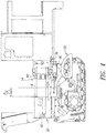
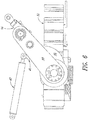
- Preferred positioning assembly 36 includes C-shaped frame portion 38, pivot assembly 40 and positioning actuator 42 (shown in Figures 4 and 6 ). Positioning actuator 42 is attached between frame 23 of the milling machine and positioning tab 43 of pivot assembly 40. Pivot assembly 40 comprises upper pivot plate 44 and lower pivot plate 46. Pivot assembly 40 also includes pivot tube 48 that is attached between upper pivot plate 44 and lower pivot plate 46. In addition, outer tube 50 is mounted between upper pivot plate 44 and lower pivot plate 46 and preferably extends through the upper pivot plate. Inner tube 34 of right rear drive assembly 28 is adapted to move vertically with respect to outer tube 50 of pivot assembly 40, as controlled by elevating actuator 52.
- C-shaped frame portion 38 is attached to frame 22 of machine 20, as best shown in Figure 4 , and includes upper frame plate 54 and lower frame plate 56. Also attached to C-shaped frame portion 38 is generally vertical pivot pin 58, which is inserted through hole 60 in upper frame plate 54, through pivot tube 48 of pivot assembly 40, and into a hole (not shown, but substantially similar to hole 60) in lower frame plate 56.
- the pivot pin and the relative dimensions of the pivot assembly and C-shaped frame portion permit pivot assembly 40 to pivot with respect to C-shaped frame portion 38, as controlled by positioning actuator 42 (shown in Figures 4 and 6 ) that is attached between positioning tab 43 of pivot assembly 40 and frame 22 of machine 20.
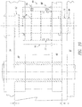
- locking actuator 69 is adapted to move pivot assembly 40 generally vertically on pivot pin 58 of C-shaped frame portion 38 between an unlocking elevation (illustrated in Figures 7 and 8 ) and a locking elevation (illustrated in Figures 9 and 10 ).
- Locking actuator 69 comprises cylinder 70 that is mounted in pivot assembly 40.
- Locking actuator 69 includes piston 72 to which is attached upper rod 74 and lower rod 76. Because of the configuration of locking actuator 69, piston 72 can move between the upper position shown in Figure 8 and the lower position shown in Figure 10 .
- pivot assembly 40 includes a pivot locking component comprising recess 78 in upper pivot plate 44 that extends from upper surface 66.
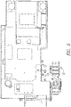
- C-shaped frame portion 38 includes a first frame locking component comprising first positioning boss 80 (see Figures 4 and 5 ) that is associated with the first position for the drive assembly, i.e., outside the housing of the milling machine.
- C-shaped frame portion 38 includes a second frame locking component comprising second positioning boss 82 (see Figures 7 , 9 and 11 ) that is associated with the second position for the drive assembly, i.e., laterally within the periphery of housing 24 of the milling machine.
- Other frame locking components (not shown) comprising one or more intermediate positioning bosses may be provided which are associated with intermediate positions for the drive assembly, i.e., between the first position shown in Figure 5 and the second position shown in Figure 11 .
- positioning actuator 42 (shown in Figures 4 and 6 ) is attached between pivot assembly 40 and frame 22 of machine 20.
- Positioning actuator 42 is adapted to pivot or move pivot assembly 40 on pivot pin 58 with respect to C-shaped frame portion 38 between a first pivot position in which the first frame locking component of the frame portion is aligned with the pivot locking component and a second pivot position in which the second frame locking component is aligned with the pivot locking component.
- Figures 7-10 illustrate the orientation of pivot assembly 40 with respect to C-shaped frame portion 38 in the second pivot position, in which the second frame locking component comprising second positioning boss 82 is aligned with the pivot locking component comprising recess 78 in upper pivot plate 44.
- FIGS 7 and 8 illustrate pivot assembly 40 in the unlocked elevation in the second pivot position
- Figures 9 and 10 illustrate pivot assembly 40 in the locked elevation
- lower pivot plate 46 of pivot assembly 40 is adjacent to lower frame plate 56 of C-shaped frame portion when the pivot assembly is in the unlocked elevation (shown in Figures 7 and 8 )
- upper pivot plate 44 of pivot assembly 40 is adjacent to upper frame plate 54 of C-shaped frame portion 38 when the pivot assembly is in the locked elevation (shown in Figures 9 and 10 ).
- pivot assembly 40 when pivot assembly 40 is in the locked elevation shown in Figures 9 and 10 , fluid may be introduced through port 88 to drive piston 72 upwardly from the position shown in Figure 10 to the position shown in Figure 8 .
- This will disengage the bottom end of lower rod 76 from recess 86 in lower frame plate 56 and will disengage positioning boss 82 from recess 78, and the reaction force generated by the movement of piston 72 will cause pivot assembly 40 to move downwardly from the locked elevation shown in Figures 9 and 10 to the unlocked elevation shown in Figures 7 and 8 .
- Steering knuckle 90 includes steering tube 92 and steering arm 94.
- Steering tube 92 is disposed over inner tube 34 below first outer tube 50, so that steering knuckle 90 may rotate about its axis (and that of the inner tube), as controlled by steering actuator 96 that is attached between the steering arm and the frame of the milling machine.
- the positioning assembly is configured so that when pivot assembly 40 is locked to C-shaped frame portion 38 in the first position (shown in Figure 5 ), steering actuator 96 cannot be operated to steer drive mechanism 32; however, when pivot assembly 40 is unlocked and the drive assembly moved towards the second position, steering actuator 96 can be used to change the orientation of the drive mechanism 32 as the drive assembly is moved between the first and second positions so that the tracks (or wheels) of the drive mechanism can be oriented to roll in a forward direction at both the first and second positions without the necessity for pivoting the drive assembly through an angle of 180°, as is required by some prior art systems.
- drive mechanism 32 When pivot assembly 40 is locked to C-shaped frame portion 38 in the second position, drive mechanism 32 is free to rotate for steering purposes by operation of steering actuator 96 that is connected between the frame and steering knuckle 90.
- Outer tube 50 is free to move vertically with respect to inner tube 34 at all positions of the drive mechanism by operation of elevating actuator 52 to adjust the cut depth of the milling drum on the right side of the machine.
- positioning actuator 42 be mounted between the positioning assembly and the frame of machine 20 in such a way as to accommodate this vertical movement.
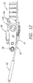
- rod 43 of positioning actuator 42 is pivotally attached to pivot arm 45 of lower pivot plate 46. This attachment is accomplished by providing ball socket insert 97 in a cavity in the end of pivot arm 45, and a mating ball 98 in the ball socket insert.
- Ball 98 includes a central bore 100 which is aligned with corresponding holes in clevis 102 on the end of rod 43 of positioning actuator 42.
- Pin 104 is placed through the holes in clevis 102 and ball 98 to secure rod 43 of positioning actuator 42 to pivot arm 45 of lower pivot plate 46 in such a manner as to permit the long axis of rod 43 to move within an angle ⁇ to accommodate vertical movement of pivot assembly 40 with respect to C-shaped frame portion 38.
- a similar ball and socket assembly is also employed at the end of positioning actuator 42 where it attaches to frame 22, although this assembly is not shown in the drawings.
- rod 106 of steering actuator 96 is pivotally attached to steering arm 94 of steering knuckle 90. This attachment is accomplished by providing ball socket insert 108 in a cavity in the end of steering arm 94, and a mating ball 110 in the ball socket insert. Ball 110 includes a central bore 112 which is aligned with corresponding holes in clevis 114 on the end of rod 106 of steering actuator 96.
- Pin 116 is placed through the holes in clevis 114 and ball 110 to secure rod 106 of steering actuator 96 to steering arm 94 of steering knuckle 90 in such a manner as to permit the long axis of rod 106 to move within an angle ⁇ to accommodate vertical movement of pivot assembly 40 with respect to C-shaped frame portion 38.
- a similar ball and socket assembly is also employed at the end of steering actuator 96 where it attaches to frame 22, although this assembly is not shown in the drawings.
- positioning assembly 36 is adapted to move right rear track drive assembly 28 between a first position which is laterally outside the periphery of the machine housing, through a number of intermediate positions and a second position which is laterally inside the periphery of the machine housing.
- This movement is accomplished by actuating elevating actuator 52 to move drive mechanism 32 from a contact position on the surface on which the milling machine is placed for operation to a raised non-contact position.
- locking actuator 69 is actuated to move pivot assembly 40 to unlock the pivot assembly from C-shaped frame portion 38
- positioning actuator 42 is actuated to pivot the pivot assembly on the pivot pin with respect to the C-shaped frame portion between the first pivot position and the second pivot position.
- Positioning actuator 42 may locate the pivot assembly at the first position, the second position, or at any intermediate position between the first position and the second position.
- Locking actuator 69 may then be actuated to move the pivot assembly with respect to the C-shaped frame portion to lock the pivot assembly to the frame portion.
- elevating actuator 52 is actuated once again to move the drive mechanism from the non-contact position to the contact position.
- Steering actuator 96 may be employed to steer the drive mechanism 32 at the first position, the second position, or at any intermediate position between the first position and the second position.
Landscapes
- Engineering & Computer Science (AREA)
- Mechanical Engineering (AREA)
- Mining & Mineral Resources (AREA)
- Architecture (AREA)
- Civil Engineering (AREA)
- Structural Engineering (AREA)
- Road Repair (AREA)
- Disintegrating Or Milling (AREA)
- Shovels (AREA)
Applications Claiming Priority (1)
| Application Number | Priority Date | Filing Date | Title |
|---|---|---|---|
| US15/187,146 US9951484B2 (en) | 2016-06-20 | 2016-06-20 | Positioning assembly for placing steerable drive in multiple positions with respect to milling machine housing |
Publications (2)
| Publication Number | Publication Date |
|---|---|
| EP3260602A1 true EP3260602A1 (de) | 2017-12-27 |
| EP3260602B1 EP3260602B1 (de) | 2018-12-12 |
Family
ID=59054008
Family Applications (1)
| Application Number | Title | Priority Date | Filing Date |
|---|---|---|---|
| EP17175459.1A Active EP3260602B1 (de) | 2016-06-20 | 2017-06-12 | Fräsmaschine zum fräsen einer oberfläche einer fahrbahn und verfahren zum bewegen einer antriebseinheit einer fräsmaschine |
Country Status (5)
| Country | Link |
|---|---|
| US (1) | US9951484B2 (de) |
| EP (1) | EP3260602B1 (de) |
| CN (1) | CN107524073B (de) |
| AU (1) | AU2017204154B2 (de) |
| CA (1) | CA2969907C (de) |
Families Citing this family (4)
| Publication number | Priority date | Publication date | Assignee | Title |
|---|---|---|---|---|
| CN111923720B (zh) * | 2019-10-24 | 2021-10-29 | 中国北方车辆研究所 | 一种四连杆型轮毂电机纵臂悬架 |
| DE102020003044A1 (de) * | 2020-05-20 | 2021-11-25 | Bomag Gmbh | Baumaschine und verfahren zur erhöhung der standsicherheit einer baumaschine |
| US12071733B2 (en) * | 2022-08-18 | 2024-08-27 | Wirtgen Gmbh | Milling attachment with adjustable cover |
| CN121250759B (zh) * | 2025-12-05 | 2026-04-10 | 湖南省高速公路集团有限公司 | 基于铣刨深度实时反馈的路面铣刨调平装置及其施工方法 |
Citations (5)
| Publication number | Priority date | Publication date | Assignee | Title |
|---|---|---|---|---|
| US6106073A (en) | 1996-08-01 | 2000-08-22 | Wirtgen Gmbh | Shiftable wheel for road milling machine |
| US20030016998A1 (en) * | 2001-06-29 | 2003-01-23 | Dubay Gregory H. | Cold planer |
| EP1381736A1 (de) * | 2001-04-27 | 2004-01-21 | BITELLI S.p.A. | Fräsvorrichtung mit wiedereinfahrbaren hinterrädern |
| US20130000996A1 (en) * | 2011-06-30 | 2013-01-03 | Caterpillar Inc. | Mobile machine with a support system |
| US9068303B2 (en) | 2012-08-22 | 2015-06-30 | Wirtgen Gmbh | Road milling machine for the treatment of road pavements, as well as method for pivoting a travelling drive unit of a road milling machine |
Family Cites Families (4)
| Publication number | Priority date | Publication date | Assignee | Title |
|---|---|---|---|---|
| IT245489Y1 (it) * | 1998-11-10 | 2002-03-20 | Bitelli Spa | Macchina scarificatrice con ruote posteriori rientranti. |
| ITTO20040499A1 (it) * | 2004-07-15 | 2004-10-15 | Bitelli Spa | Macchina operatrice in particolare scarificatrice stradale |
| US7331636B2 (en) * | 2004-10-07 | 2008-02-19 | Prep Engineering, Inc. | Electric milling machine |
| DE102010034662A1 (de) * | 2010-03-02 | 2011-09-08 | Bomag Gmbh | Straßenbaumaschine zum Bearbeiten von Fahrbahnen |
-
2016
- 2016-06-20 US US15/187,146 patent/US9951484B2/en active Active
-
2017
- 2017-06-06 CA CA2969907A patent/CA2969907C/en active Active
- 2017-06-12 EP EP17175459.1A patent/EP3260602B1/de active Active
- 2017-06-19 AU AU2017204154A patent/AU2017204154B2/en not_active Ceased
- 2017-06-20 CN CN201710469787.XA patent/CN107524073B/zh not_active Expired - Fee Related
Patent Citations (5)
| Publication number | Priority date | Publication date | Assignee | Title |
|---|---|---|---|---|
| US6106073A (en) | 1996-08-01 | 2000-08-22 | Wirtgen Gmbh | Shiftable wheel for road milling machine |
| EP1381736A1 (de) * | 2001-04-27 | 2004-01-21 | BITELLI S.p.A. | Fräsvorrichtung mit wiedereinfahrbaren hinterrädern |
| US20030016998A1 (en) * | 2001-06-29 | 2003-01-23 | Dubay Gregory H. | Cold planer |
| US20130000996A1 (en) * | 2011-06-30 | 2013-01-03 | Caterpillar Inc. | Mobile machine with a support system |
| US9068303B2 (en) | 2012-08-22 | 2015-06-30 | Wirtgen Gmbh | Road milling machine for the treatment of road pavements, as well as method for pivoting a travelling drive unit of a road milling machine |
Also Published As
| Publication number | Publication date |
|---|---|
| CA2969907C (en) | 2018-12-11 |
| CA2969907A1 (en) | 2017-12-20 |
| US9951484B2 (en) | 2018-04-24 |
| CN107524073A (zh) | 2017-12-29 |
| EP3260602B1 (de) | 2018-12-12 |
| US20170362782A1 (en) | 2017-12-21 |
| AU2017204154B2 (en) | 2020-05-14 |
| AU2017204154A1 (en) | 2018-01-18 |
| CN107524073B (zh) | 2020-04-21 |
Similar Documents
| Publication | Publication Date | Title |
|---|---|---|
| AU2017204154B2 (en) | Positioning assembly for placing steerable drive in multiple positions with respect to milling machine housing | |
| US8813864B2 (en) | Support system for a box blade attached to a tractor | |
| EP1381736B1 (de) | Fräsvorrichtung mit wiedereinfahrbaren hinterrädern | |
| JP3357643B2 (ja) | 地面を破壊するための機械 | |
| US9507348B2 (en) | Auto-calibration of automatic grade control system in a working machine | |
| CA3071608C (en) | Drive belt disengagement for cutter drum of milling machine and auxiliary drum drive assembly | |
| US20230339050A1 (en) | Self-propelled welding machine for butt welding pipes | |
| US20030016998A1 (en) | Cold planer | |
| EP4455413B1 (de) | Verfahren zum betreiben einer anbaufräse für eine arbeitsmaschine und arbeitsmaschine | |
| US12351994B2 (en) | Guidance system for road construction machines | |
| AU2019226209B2 (en) | Side cutter for milling machine | |
| CA3023309C (en) | Adjustable-width modular broom assembly for sweeping machine | |
| CA3054648A1 (en) | Side cutter for milling machine | |
| US10787775B2 (en) | Auxiliary drum drive assembly for milling machine | |
| CN119221547A (zh) | 一种矿山工程用多刮铲刀式电动平地机 | |
| CZ7404U1 (cs) | Protismykový povrch vozovky a zařízení pro jeho realizaci |
Legal Events
| Date | Code | Title | Description |
|---|---|---|---|
| PUAI | Public reference made under article 153(3) epc to a published international application that has entered the european phase |
Free format text: ORIGINAL CODE: 0009012 |
|
| STAA | Information on the status of an ep patent application or granted ep patent |
Free format text: STATUS: THE APPLICATION HAS BEEN PUBLISHED |
|
| AK | Designated contracting states |
Kind code of ref document: A1 Designated state(s): AL AT BE BG CH CY CZ DE DK EE ES FI FR GB GR HR HU IE IS IT LI LT LU LV MC MK MT NL NO PL PT RO RS SE SI SK SM TR |
|
| AX | Request for extension of the european patent |
Extension state: BA ME |
|
| STAA | Information on the status of an ep patent application or granted ep patent |
Free format text: STATUS: REQUEST FOR EXAMINATION WAS MADE |
|
| 17P | Request for examination filed |
Effective date: 20180530 |
|
| RBV | Designated contracting states (corrected) |
Designated state(s): AL AT BE BG CH CY CZ DE DK EE ES FI FR GB GR HR HU IE IS IT LI LT LU LV MC MK MT NL NO PL PT RO RS SE SI SK SM TR |
|
| GRAP | Despatch of communication of intention to grant a patent |
Free format text: ORIGINAL CODE: EPIDOSNIGR1 |
|
| STAA | Information on the status of an ep patent application or granted ep patent |
Free format text: STATUS: GRANT OF PATENT IS INTENDED |
|
| INTG | Intention to grant announced |
Effective date: 20180817 |
|
| GRAS | Grant fee paid |
Free format text: ORIGINAL CODE: EPIDOSNIGR3 |
|
| GRAA | (expected) grant |
Free format text: ORIGINAL CODE: 0009210 |
|
| STAA | Information on the status of an ep patent application or granted ep patent |
Free format text: STATUS: THE PATENT HAS BEEN GRANTED |
|
| AK | Designated contracting states |
Kind code of ref document: B1 Designated state(s): AL AT BE BG CH CY CZ DE DK EE ES FI FR GB GR HR HU IE IS IT LI LT LU LV MC MK MT NL NO PL PT RO RS SE SI SK SM TR |
|
| REG | Reference to a national code |
Ref country code: GB Ref legal event code: FG4D |
|
| REG | Reference to a national code |
Ref country code: CH Ref legal event code: EP |
|
| REG | Reference to a national code |
Ref country code: AT Ref legal event code: REF Ref document number: 1076129 Country of ref document: AT Kind code of ref document: T Effective date: 20181215 |
|
| REG | Reference to a national code |
Ref country code: DE Ref legal event code: R096 Ref document number: 602017001347 Country of ref document: DE |
|
| REG | Reference to a national code |
Ref country code: IE Ref legal event code: FG4D |
|
| REG | Reference to a national code |
Ref country code: NL Ref legal event code: MP Effective date: 20181212 |
|
| REG | Reference to a national code |
Ref country code: LT Ref legal event code: MG4D |
|
| PG25 | Lapsed in a contracting state [announced via postgrant information from national office to epo] |
Ref country code: BG Free format text: LAPSE BECAUSE OF FAILURE TO SUBMIT A TRANSLATION OF THE DESCRIPTION OR TO PAY THE FEE WITHIN THE PRESCRIBED TIME-LIMIT Effective date: 20190312 Ref country code: NO Free format text: LAPSE BECAUSE OF FAILURE TO SUBMIT A TRANSLATION OF THE DESCRIPTION OR TO PAY THE FEE WITHIN THE PRESCRIBED TIME-LIMIT Effective date: 20190312 Ref country code: HR Free format text: LAPSE BECAUSE OF FAILURE TO SUBMIT A TRANSLATION OF THE DESCRIPTION OR TO PAY THE FEE WITHIN THE PRESCRIBED TIME-LIMIT Effective date: 20181212 Ref country code: LV Free format text: LAPSE BECAUSE OF FAILURE TO SUBMIT A TRANSLATION OF THE DESCRIPTION OR TO PAY THE FEE WITHIN THE PRESCRIBED TIME-LIMIT Effective date: 20181212 Ref country code: FI Free format text: LAPSE BECAUSE OF FAILURE TO SUBMIT A TRANSLATION OF THE DESCRIPTION OR TO PAY THE FEE WITHIN THE PRESCRIBED TIME-LIMIT Effective date: 20181212 Ref country code: ES Free format text: LAPSE BECAUSE OF FAILURE TO SUBMIT A TRANSLATION OF THE DESCRIPTION OR TO PAY THE FEE WITHIN THE PRESCRIBED TIME-LIMIT Effective date: 20181212 Ref country code: LT Free format text: LAPSE BECAUSE OF FAILURE TO SUBMIT A TRANSLATION OF THE DESCRIPTION OR TO PAY THE FEE WITHIN THE PRESCRIBED TIME-LIMIT Effective date: 20181212 |
|
| REG | Reference to a national code |
Ref country code: AT Ref legal event code: MK05 Ref document number: 1076129 Country of ref document: AT Kind code of ref document: T Effective date: 20181212 |
|
| PG25 | Lapsed in a contracting state [announced via postgrant information from national office to epo] |
Ref country code: GR Free format text: LAPSE BECAUSE OF FAILURE TO SUBMIT A TRANSLATION OF THE DESCRIPTION OR TO PAY THE FEE WITHIN THE PRESCRIBED TIME-LIMIT Effective date: 20190313 Ref country code: SE Free format text: LAPSE BECAUSE OF FAILURE TO SUBMIT A TRANSLATION OF THE DESCRIPTION OR TO PAY THE FEE WITHIN THE PRESCRIBED TIME-LIMIT Effective date: 20181212 Ref country code: RS Free format text: LAPSE BECAUSE OF FAILURE TO SUBMIT A TRANSLATION OF THE DESCRIPTION OR TO PAY THE FEE WITHIN THE PRESCRIBED TIME-LIMIT Effective date: 20181212 Ref country code: AL Free format text: LAPSE BECAUSE OF FAILURE TO SUBMIT A TRANSLATION OF THE DESCRIPTION OR TO PAY THE FEE WITHIN THE PRESCRIBED TIME-LIMIT Effective date: 20181212 |
|
| PG25 | Lapsed in a contracting state [announced via postgrant information from national office to epo] |
Ref country code: NL Free format text: LAPSE BECAUSE OF FAILURE TO SUBMIT A TRANSLATION OF THE DESCRIPTION OR TO PAY THE FEE WITHIN THE PRESCRIBED TIME-LIMIT Effective date: 20181212 |
|
| PG25 | Lapsed in a contracting state [announced via postgrant information from national office to epo] |
Ref country code: PL Free format text: LAPSE BECAUSE OF FAILURE TO SUBMIT A TRANSLATION OF THE DESCRIPTION OR TO PAY THE FEE WITHIN THE PRESCRIBED TIME-LIMIT Effective date: 20181212 Ref country code: CZ Free format text: LAPSE BECAUSE OF FAILURE TO SUBMIT A TRANSLATION OF THE DESCRIPTION OR TO PAY THE FEE WITHIN THE PRESCRIBED TIME-LIMIT Effective date: 20181212 Ref country code: PT Free format text: LAPSE BECAUSE OF FAILURE TO SUBMIT A TRANSLATION OF THE DESCRIPTION OR TO PAY THE FEE WITHIN THE PRESCRIBED TIME-LIMIT Effective date: 20190412 Ref country code: IT Free format text: LAPSE BECAUSE OF FAILURE TO SUBMIT A TRANSLATION OF THE DESCRIPTION OR TO PAY THE FEE WITHIN THE PRESCRIBED TIME-LIMIT Effective date: 20181212 |
|
| PG25 | Lapsed in a contracting state [announced via postgrant information from national office to epo] |
Ref country code: IS Free format text: LAPSE BECAUSE OF FAILURE TO SUBMIT A TRANSLATION OF THE DESCRIPTION OR TO PAY THE FEE WITHIN THE PRESCRIBED TIME-LIMIT Effective date: 20190412 Ref country code: SM Free format text: LAPSE BECAUSE OF FAILURE TO SUBMIT A TRANSLATION OF THE DESCRIPTION OR TO PAY THE FEE WITHIN THE PRESCRIBED TIME-LIMIT Effective date: 20181212 Ref country code: SK Free format text: LAPSE BECAUSE OF FAILURE TO SUBMIT A TRANSLATION OF THE DESCRIPTION OR TO PAY THE FEE WITHIN THE PRESCRIBED TIME-LIMIT Effective date: 20181212 Ref country code: EE Free format text: LAPSE BECAUSE OF FAILURE TO SUBMIT A TRANSLATION OF THE DESCRIPTION OR TO PAY THE FEE WITHIN THE PRESCRIBED TIME-LIMIT Effective date: 20181212 Ref country code: RO Free format text: LAPSE BECAUSE OF FAILURE TO SUBMIT A TRANSLATION OF THE DESCRIPTION OR TO PAY THE FEE WITHIN THE PRESCRIBED TIME-LIMIT Effective date: 20181212 |
|
| REG | Reference to a national code |
Ref country code: DE Ref legal event code: R097 Ref document number: 602017001347 Country of ref document: DE |
|
| PLBE | No opposition filed within time limit |
Free format text: ORIGINAL CODE: 0009261 |
|
| STAA | Information on the status of an ep patent application or granted ep patent |
Free format text: STATUS: NO OPPOSITION FILED WITHIN TIME LIMIT |
|
| PG25 | Lapsed in a contracting state [announced via postgrant information from national office to epo] |
Ref country code: DK Free format text: LAPSE BECAUSE OF FAILURE TO SUBMIT A TRANSLATION OF THE DESCRIPTION OR TO PAY THE FEE WITHIN THE PRESCRIBED TIME-LIMIT Effective date: 20181212 Ref country code: SI Free format text: LAPSE BECAUSE OF FAILURE TO SUBMIT A TRANSLATION OF THE DESCRIPTION OR TO PAY THE FEE WITHIN THE PRESCRIBED TIME-LIMIT Effective date: 20181212 Ref country code: AT Free format text: LAPSE BECAUSE OF FAILURE TO SUBMIT A TRANSLATION OF THE DESCRIPTION OR TO PAY THE FEE WITHIN THE PRESCRIBED TIME-LIMIT Effective date: 20181212 |
|
| 26N | No opposition filed |
Effective date: 20190913 |
|
| PG25 | Lapsed in a contracting state [announced via postgrant information from national office to epo] |
Ref country code: MC Free format text: LAPSE BECAUSE OF FAILURE TO SUBMIT A TRANSLATION OF THE DESCRIPTION OR TO PAY THE FEE WITHIN THE PRESCRIBED TIME-LIMIT Effective date: 20181212 |
|
| REG | Reference to a national code |
Ref country code: BE Ref legal event code: MM Effective date: 20190630 |
|
| PG25 | Lapsed in a contracting state [announced via postgrant information from national office to epo] |
Ref country code: TR Free format text: LAPSE BECAUSE OF FAILURE TO SUBMIT A TRANSLATION OF THE DESCRIPTION OR TO PAY THE FEE WITHIN THE PRESCRIBED TIME-LIMIT Effective date: 20181212 |
|
| PG25 | Lapsed in a contracting state [announced via postgrant information from national office to epo] |
Ref country code: IE Free format text: LAPSE BECAUSE OF NON-PAYMENT OF DUE FEES Effective date: 20190612 |
|
| PG25 | Lapsed in a contracting state [announced via postgrant information from national office to epo] |
Ref country code: LU Free format text: LAPSE BECAUSE OF NON-PAYMENT OF DUE FEES Effective date: 20190612 Ref country code: BE Free format text: LAPSE BECAUSE OF NON-PAYMENT OF DUE FEES Effective date: 20190630 |
|
| PG25 | Lapsed in a contracting state [announced via postgrant information from national office to epo] |
Ref country code: FR Free format text: LAPSE BECAUSE OF NON-PAYMENT OF DUE FEES Effective date: 20190630 |
|
| REG | Reference to a national code |
Ref country code: CH Ref legal event code: PL |
|
| PG25 | Lapsed in a contracting state [announced via postgrant information from national office to epo] |
Ref country code: LI Free format text: LAPSE BECAUSE OF NON-PAYMENT OF DUE FEES Effective date: 20200630 Ref country code: CH Free format text: LAPSE BECAUSE OF NON-PAYMENT OF DUE FEES Effective date: 20200630 |
|
| PG25 | Lapsed in a contracting state [announced via postgrant information from national office to epo] |
Ref country code: CY Free format text: LAPSE BECAUSE OF FAILURE TO SUBMIT A TRANSLATION OF THE DESCRIPTION OR TO PAY THE FEE WITHIN THE PRESCRIBED TIME-LIMIT Effective date: 20181212 |
|
| PG25 | Lapsed in a contracting state [announced via postgrant information from national office to epo] |
Ref country code: MT Free format text: LAPSE BECAUSE OF FAILURE TO SUBMIT A TRANSLATION OF THE DESCRIPTION OR TO PAY THE FEE WITHIN THE PRESCRIBED TIME-LIMIT Effective date: 20181212 Ref country code: HU Free format text: LAPSE BECAUSE OF FAILURE TO SUBMIT A TRANSLATION OF THE DESCRIPTION OR TO PAY THE FEE WITHIN THE PRESCRIBED TIME-LIMIT; INVALID AB INITIO Effective date: 20170612 |
|
| GBPC | Gb: european patent ceased through non-payment of renewal fee |
Effective date: 20210612 |
|
| PG25 | Lapsed in a contracting state [announced via postgrant information from national office to epo] |
Ref country code: GB Free format text: LAPSE BECAUSE OF NON-PAYMENT OF DUE FEES Effective date: 20210612 |
|
| PG25 | Lapsed in a contracting state [announced via postgrant information from national office to epo] |
Ref country code: MK Free format text: LAPSE BECAUSE OF FAILURE TO SUBMIT A TRANSLATION OF THE DESCRIPTION OR TO PAY THE FEE WITHIN THE PRESCRIBED TIME-LIMIT Effective date: 20181212 |
|
| P01 | Opt-out of the competence of the unified patent court (upc) registered |
Effective date: 20230526 |
|
| PGFP | Annual fee paid to national office [announced via postgrant information from national office to epo] |
Ref country code: DE Payment date: 20250619 Year of fee payment: 9 |
|
| REG | Reference to a national code |
Ref country code: DE Ref legal event code: R082 Ref document number: 602017001347 Country of ref document: DE Representative=s name: DR. RIEBLING & PARTNER PATENTANWAELTE MBB, DE |