EP3260607B1 - Siphon - Google Patents
Siphon Download PDFInfo
- Publication number
- EP3260607B1 EP3260607B1 EP16175445.2A EP16175445A EP3260607B1 EP 3260607 B1 EP3260607 B1 EP 3260607B1 EP 16175445 A EP16175445 A EP 16175445A EP 3260607 B1 EP3260607 B1 EP 3260607B1
- Authority
- EP
- European Patent Office
- Prior art keywords
- siphon
- outlet
- connection piece
- inlet
- arrangement
- Prior art date
- Legal status (The legal status is an assumption and is not a legal conclusion. Google has not performed a legal analysis and makes no representation as to the accuracy of the status listed.)
- Active
Links
Images


Classifications
-
- E—FIXED CONSTRUCTIONS
- E03—WATER SUPPLY; SEWERAGE
- E03C—DOMESTIC PLUMBING INSTALLATIONS FOR FRESH WATER OR WASTE WATER; SINKS
- E03C1/00—Domestic plumbing installations for fresh water or waste water; Sinks
- E03C1/12—Plumbing installations for waste water; Basins or fountains connected thereto; Sinks
- E03C1/28—Odour seals
- E03C1/284—Odour seals having U-shaped trap
-
- E—FIXED CONSTRUCTIONS
- E03—WATER SUPPLY; SEWERAGE
- E03C—DOMESTIC PLUMBING INSTALLATIONS FOR FRESH WATER OR WASTE WATER; SINKS
- E03C1/00—Domestic plumbing installations for fresh water or waste water; Sinks
- E03C1/12—Plumbing installations for waste water; Basins or fountains connected thereto; Sinks
- E03C1/28—Odour seals
- E03C1/29—Odour seals having housing containing dividing wall, e.g. tubular
Definitions
- the present invention relates to a siphon according to the preamble of claim 1.
- Siphons are known from the prior art as odor traps.
- a siphon has become known, which can be mounted in particular below a washstand or a sink.
- a disadvantage of the siphon according to the EP 1 447 486 is that when cleaning the siphon, the housing part must be removed and the water in the siphon can escape from the housing in an uncontrolled manner. The siphon can therefore not be cleaned without the help of a catch basin.
- the EP 2 256 261 discloses a siphon which has the same drawbacks as the above. From the DE 37 25 076 and the WO 96/15330 other siphons have become known.
- the invention has for its object to provide a siphon that overcomes the disadvantages of the above-mentioned prior art.
- it is a task that an uncontrolled leakage of water in the case of cleaning can be largely avoided.
- a siphon arrangement comprises a housing with an inlet socket, an outlet socket and a siphon receptacle arranged between the inlet socket and outlet socket, and a siphon element arranged in the siphon socket with a siphon section and an inlet facing the inlet socket and a Outlet port leading outlet.
- Water can be led from the inlet connection via the inlet into the siphon section and from the outlet to the outlet connection.
- a drain line of a sanitary fitting such as a wash basin or a sink, can be connected to the inlet connection and a waste water line can be connected to the outlet connection.
- the siphon element can be moved, in particular pivoted, in the housing from a use position into a maintenance position and can be removed, in particular pulled out, from the housing from the maintenance position.
- the siphon element is designed such that when the siphon element moves, the water in the siphon section at least partially flows to the outlet port and that any residual water in the siphon section cannot flow out of the siphon section when the siphon element is removed.
- the described design of the siphon element has the advantage that the water located in the siphon section can flow out of the siphon section in a controlled manner, at least partially or completely, via the outlet connection. This prevents the water from escaping uncontrollably during maintenance work, which will typically result in water damage or major cleaning work.
- a wall preferably surrounds the siphon section essentially completely, apart from the entry and the exit.
- the siphon section is designed as a channel which is closed overleaf.
- This training has the advantage that the siphon can act as a kind of vessel. This means that the residual water in the siphon cannot flow out of the siphon section when the siphon element is removed.
- the siphon element is particularly preferably pivotable through an angle of at most 90 °.
- the angle can also be less than 90 °, which has the advantage that not all elements located in the siphon section, such as a piece of jewelry, are emptied out of the siphon section during the movement of the siphon element.
- the entry in the use position is preferably substantially higher or higher the same height as the exit.
- the siphon section extends from the inlet in the direction of gravity downwards and then upwards again to the outlet.
- the arrangement of the inlet and outlet at the same height has the advantage that standing water in the siphon section is always only in the area which is surrounded by the wall, which is advantageous for the stress on the seals.
- the outlet is preferably moved against the outlet connection during the movement into the maintenance position, the outlet then being lower than the inlet.
- the water lying in the siphon section can then escape wholly or at least partially through the outlet from the siphon section and flows out via the outlet connection.
- the siphon section is preferably provided by a partition projecting into the siphon section, the partition preferably extending between the inlet and outlet and providing a passage in the lower region.
- the lower area is opposite the entrance and exit.
- the passage is preferably at the lowest point of the siphon section.
- the siphon holder has a cylindrical bearing wall for storing the siphon element.
- the bearing wall seen from the inlet connection, is perforated with the inlet connection.
- the inlet connector breaks through the bearing wall and opens into the siphon holder.
- the bearing wall is perforated with the outlet nozzle when viewed towards the outlet nozzle. The outlet connector therefore joins the bearing wall.
- the bearing wall preferably delimits an access opening via which the siphon element can be inserted into the siphon receptacle.
- At least one seal extends completely around the inlet, which seal cooperates with said bearing wall and extends completely around the mouth of the inlet connector.
- the cylindrical bearing wall preferably has at least one completely circumferential wall section and the siphon element has an outer wall with at least one completely circumferential wall section, at least one completely circumferential sealing element being arranged between the two wall sections.
- the gap between the wall section and the bearing wall is sealed with the sealing element.
- a peripheral wall section is particularly preferably arranged in the vicinity of the access opening from the outside into the bearing section. In terms of access, this means that no water can escape from it.
- Two circumferential sealing elements which are spaced apart from one another are particularly preferably arranged, the inlet or the outlet being located between the sealing elements.
- the sealing elements surround the corresponding wall section in such a way that the entry or the exit lies between the two sealing elements.
- Parts of the seal which surrounds the inlet are preferably provided by parts of the sealing element.
- a simple sealing structure can thus be created using the same seal.
- the outlet connector is preferably arranged relative to the inlet connector in such a way that water flows from the inlet connector into the outlet connector when the siphon element is not inserted. This is advantageous if water enters the siphon arrangement via the inlet when the siphon element is not inserted. This water will then flow through the siphon arrangement and leave it through the outlet connection, so that water damage can be largely prevented.
- the outlet connection is preferably arranged in such a way that the outlet of the siphon section opens into the outlet at every position of the siphon element.
- the outlet connector has an extent which is such that the outlet always opens into the outlet connector regardless of the position of the siphon element.
- the outlet connector therefore has a larger cross section than the outlet, the outlet being relatively in the region of this cross section or in the region of the Exhaust port can move.
- the siphon element is preferably mounted in the housing via a bayonet lock or self-locking.
- the bayonet catch is preferably designed such that the siphon element can only be inserted into the housing in the correct position.
- the siphon element preferably has an actuating element which is accessible from outside the housing.
- the actuating element is preferably designed such that it can be gripped easily by hand without the aid of a tool.
- a siphon arrangement 1 according to an embodiment of the present invention shown.
- the siphon arrangement 1 comprises a housing 2 with an inlet connection 3, an outlet connection 4 and a siphon receptacle 5 arranged between the inlet connection 3 and the outlet connection 4.
- the siphon arrangement 1 comprises a siphon element 6 arranged or stored in the siphon receptacle 5 with a siphon section 7 and one Inlet pipe 3 facing inlet 8 and an outlet 9 leading to outlet pipe 4.
- Siphon section 7 acts as an odor trap. Water is led from the inlet nozzle 3 via the inlet 8 into the siphon section 7, then passes through the siphon section 7 and can then be led away from the siphon section 7 via the outlet 9 to the outlet nozzle 4. The water flows through the siphon section 7.
- the siphon element 6 is in the siphon receptacle 5 in the housing 2 from a position of use, as in the Figure 1 is shown movably mounted in a maintenance position.
- the siphon element 6 can be pivoted about a pivot axis S.
- the swivel angle can be up to 90 °.
- the siphon element 6 can be removed from the housing 2 from the maintenance position. In the embodiment shown, it is pulled out of the siphon holder 5 along the pivot axis S. In the Figure 2 the removed siphon element 6 is shown.
- the siphon element 6 is designed such that when the siphon element 6 moves, the water lying in the siphon section 7 flows at least partially to the outlet connection 4.
- the water lying in the siphon section 7 is symbolized by a dashed line W.
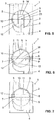
- the siphon element 6 is shown in the use position.
- the siphon section 7 is filled with water up to the line W, which runs through the inlet 8 and the outlet 9.
- the siphon element 6 from the use position in the Maintenance position swiveled, the water lying in the siphon section 7 can flow out via the outlet 9 in the direction of the outlet connection 4. This is in the Figure 6 symbolized by the arrow P.
- the siphon element 6 is further designed such that any residual water in the siphon section 7 cannot flow out of the siphon section 7 when the siphon element 6 is removed.
- the siphon section 7 is designed as a type of "cup", the water then remaining in this "cup”.
- the siphon section 7 is delimited by a wall 10.
- the wall 10 essentially completely surrounds the siphon section 7, apart from the inlet 8 and the outlet 9.
- the siphon section 7 is formed by the wall 10 as a channel closed on the reverse, whereby the "cup" just mentioned can be provided.
- the inlet 8 of the siphon section 7 is essentially at the same height as the outlet 9.
- the outlet 9 can then be moved against the outlet connection 4 during the movement from the use position into the maintenance position, the outlet 9 then being located lower comes as the entry 8. This is in the Figures 6 and 7 shown accordingly.
- the siphon section 7 is provided by a partition 11 projecting into the siphon section 7.
- the partition 11 extends in the in Figure 3 The embodiment shown between the inlet 8 and the outlet 9.
- a passage 12 is arranged in the lower region of the partition 11. This passage 12 provides the actual siphon effect.
- the Inlet 8 is followed by a descending siphon section as far as passage 12 and that the passage ascending siphon section is joined to outlet 9, the two siphon sections being separated from one another by partition 11.
- the siphon holder 5 has a cylindrical bearing wall 13.
- the siphon element 6 is mounted in this cylindrical bearing wall 13.
- the siphon element 6 also has a cylindrical outer wall 15 which has at least one completely circumferential wall section 19.
- the siphon element 6 is in contact with the siphon holder 5 via the seals described below.
- the bearing wall 13 of the siphon receptacle 5 is seen through the inlet nozzle 3 from the inlet nozzle 3. This means that the inlet nozzle 3 opens into the siphon receptacle 5 through the bearing wall 13.
- the bearing wall 13 is perforated with the outlet nozzle 5 as seen towards the outlet nozzle 4.
- the outlet port 4 also protrudes through the bearing wall 13 into the siphon holder 5. The water passes through the corresponding openings through the bearing wall 13.
- the bearing wall 13 delimits an access opening 24, via which the siphon element 6 can be inserted into the siphon receptacle 5.
- the siphon element 6 can be pivoted in the siphon holder 5, as described above.
- a seal 16 extends completely around the inlet 8.
- the seal 16 works together with the said bearing wall 13 and completely seals the mouth of the inlet connector in the area of the inlet 8.
- a further seal 17 is also arranged.
- the cylindrical bearing wall 13 has at least one completely circumferential wall section 18 and the outer wall 15 of the siphon element 6 also has a completely circumferential wall section 19. At least one completely circumferential sealing element 20, 21 is arranged between these two wall sections 18, 19. In the embodiment shown, a separate seal 21 is arranged, which lies between the access opening 24 and the inlet connector 3 or in the outlet connector 4. The seal 20 is mounted in a recess 25 in the housing in the region of the bearing wall 13.
- sealing elements 21 are arranged in the area of the outer wall 15 of the siphon element.
- two sealing elements 21 are provided, which are arranged such that the inlet 8 or the outlet 9 is arranged between these two circumferential sealing elements 21. These sealing elements 21 work together with the wall section 18 of the bearing wall 13.
- the sealing element 20 ensures that no water can escape between the separation point between the siphon element 6 and the siphon holder 5.
- the sealing elements 21 and the two seals 16, 17 ensure that no water can get into the intermediate area between the siphon element 6 and the siphon holder 5.
- the outlet connection 4 is arranged relative to the inlet connection 3 such that water flows from the inlet connection 3 into the outlet connection 4 when the siphon element 6 is not inserted.
- the outlet connector 4 has such a large cross section that it extends in the vertical direction as far as below the inlet connector 3. Furthermore, the outlet connection 4 is arranged such that the outlet 9 of the siphon element opens into the outlet connection 4 at every position of the siphon element.
- the siphon element 6 is mounted in the housing 2 via a bayonet lock 22.
- the bayonet catch 2 is arranged in such a way that it lies outside the water-carrying parts.
- the bayonet catch 22 has two clamping tabs 26 in the embodiment shown. One of the two clamping tabs is designed differently than the other of the two clamping tabs, so that it is ensured that the siphon element 6 can only be inserted into the housing 2 in the correct position.
- the siphon element 6 has an actuating element 23 accessible from outside the housing 2.
- the actuating element 23 is thus designed as a web, which can be easily gripped by a user by hand.
Landscapes
- Engineering & Computer Science (AREA)
- Environmental & Geological Engineering (AREA)
- Health & Medical Sciences (AREA)
- Life Sciences & Earth Sciences (AREA)
- Hydrology & Water Resources (AREA)
- Public Health (AREA)
- Water Supply & Treatment (AREA)
- Jet Pumps And Other Pumps (AREA)
- Sink And Installation For Waste Water (AREA)
- Apparatus For Making Beverages (AREA)
Claims (14)
- Agencement de siphon (1) comprenantun boîtier (2) avec un raccord d'entrée (3), un raccord de sortie (4) ainsi qu'un réceptacle de siphon (5) agencé entre le raccord d'entrée (3) et le raccord de sortie (4), etun élément de siphon (6) agencé dans le réceptacle de siphon (5) avec une section de siphon (7) ainsi qu'une entrée (8) faisant face au raccord d'entrée (3) et une sortie (9) menant au raccord de sortie (4),où l'eau peut être acheminée depuis le raccord d'entrée (3) via l'entrée (8) dans la section de siphon (7) et depuis la sortie (9) vers le raccord de sortie (4),où l'élément de siphon (6) est monté de manière à pouvoir être déplacé, préférablement pivoté, dans le boîtier (2) depuis une position d'utilisation vers une position d'entretien et peut être retiré, de préférence peut être extrait, du boîtier (2),où l'élément de siphon (6) est conçu de telle sorte que lors d'un déplacement de l'élément de siphon (6), l'eau se trouvant dans la section de siphon (7) s'écoule au moins partiellement vers le raccord de de sortie (4) etque l'élément de siphon (6) est conçu de telle sorte que toute eau résiduelle dans la section de siphon (7) ne puisse pas s'écouler hors de la section de siphon (7) lorsque l'élément de siphon (6) est retiré respectivement extrait,où le réceptacle de siphon (5) présente une paroi de montage cylindrique (13) pour le montage de l'élément de siphon (6), la paroi de montage (13), vue depuis le raccord d'entrée (3), est percée par le raccord d'entrée (3), caractérisée en ce quela paroi de montage (13), vue vers le raccord de sortie (4), est percée par le raccord de sortie (4),et qu'au moins un joint (16, 17) s'étend complètement autour de l'entrée (8), lequel joint (16, 17) coopère avec ladite paroi de montage (13) et s'étend complètement autour de l'embouchure du raccord d'entrée (3).
- Agencement de siphon (1) selon la revendication 1, caractérisé en ce qu'une paroi (10) entoure sensiblement complètement la section de siphon (7), en dehors de l'entrée (8) et de la sortie (9).
- Agencement de siphon (1) selon la revendication 1 ou 2, caractérisé en ce que l'élément de siphon (6) est pivotable selon un angle d'au plus 90°.
- Agencement de siphon (1) selon l'une des revendications précédentes, caractérisé en ce que l'entrée (8) dans la position d'utilisation est sensiblement à la même hauteur ou plus haute que la sortie (9) et / ou en ce que la sortie (9), lors du déplacement dans la position d'entretien, est déplacée contre le raccord de sortie (4), la sortie (9) étant alors inférieure à l'entrée (8).
- Agencement de siphon (1) selon l'une des revendications précédentes, caractérisé en ce que dans la section de siphon (7), une paroi de séparation (11) faisant saillie dans la section de siphon (7) est pourvue, où la paroi de séparation (11) s'étend de préférence entre l'entrée (8) et la sortie (9) et fournit un passage (12) dans la zone inférieure.
- Agencement de siphon (1) selon l'une des revendications précédentes, caractérisé en ce que la paroi de montage (13) délimite une ouverture d'accès (24) à travers laquelle l'élément de siphon (6) peut être inséré dans le réceptacle de siphon (5).
- Agencement de siphon (1) selon l'une des revendications précédentes, caractérisé en ce que la paroi de montage cylindrique (13) a au moins une section de paroi complètement circonférentielle (18) et en ce que la paroi externe (15) de l'élément de l'élément de siphon (6) a au moins une section de paroi complètement circonférentielle (19), dans lequel au moins un élément d'étanchéité complètement circonférentiel (20, 21) est disposé entre les deux sections de paroi (18, 19).
- Agencement de siphon (1) selon la revendication 7, caractérisé en ce que deux éléments d'étanchéité circonférentiels (21) sont disposés espacés l'un de l'autre, où l'entrée respectivement la sortie est située entre les éléments d'étanchéité (21).
- Agencement de siphon (1) selon la revendication 8, caractérisé en ce que des parties du joint (16, 17) sont constituées par des parties de l'élément d'étanchéité (20, 21).
- Agencement de siphon (1) selon l'une des revendications précédentes, caractérisé en ce que le raccord de sortie (4) est disposé par rapport au raccord d'entrée (3) de telle sorte que l'eau s'écoule depuis le raccord d'entrée (3) dans le raccord de sortie (4) lorsque l'élément de siphon (6) n'est pas inséré,
- Agencement de siphon (1) selon l'une des revendications précédentes, caractérisé en ce que le raccord de sortie (4) est agencé de sorte que la sortie (9) de la section de siphon (7) débouche dans le raccord de sortie (4) à chaque position de l'élément de siphon (6).
- Agencement de siphon (1) selon l'une des revendications précédentes, caractérisé en ce que l'élément de siphon (6) est monté dans le boîtier (2) via un verrou à baïonnette (22) ou de manière autobloquante.
- Agencement de siphon (1) selon la revendication 12, caractérisé en ce que le verrou à baïonnette (22) est conçu de sorte que l'élément de siphon ne peut être inséré dans le boîtier que dans la position correcte.
- Agencement de siphon (1) selon l'une des revendications précédentes, caractérisé en ce que l'élément de siphon (6) présente un élément d'actionnement (23) accessible depuis l'extérieur du boîtier (2).
Priority Applications (6)
| Application Number | Priority Date | Filing Date | Title |
|---|---|---|---|
| EP16175445.2A EP3260607B1 (fr) | 2016-06-21 | 2016-06-21 | Siphon |
| EP17167952.5A EP3260608B1 (fr) | 2016-06-21 | 2017-04-25 | Ensemble de siphon |
| US16/607,938 US11280076B2 (en) | 2016-06-21 | 2017-11-15 | Siphon |
| AU2017411393A AU2017411393B2 (en) | 2016-06-21 | 2017-11-15 | Siphon |
| PCT/EP2017/079294 WO2018197026A1 (fr) | 2016-06-21 | 2017-11-15 | Siphon |
| CN201780089954.6A CN110546333B (zh) | 2016-06-21 | 2017-11-15 | 虹吸管 |
Applications Claiming Priority (1)
| Application Number | Priority Date | Filing Date | Title |
|---|---|---|---|
| EP16175445.2A EP3260607B1 (fr) | 2016-06-21 | 2016-06-21 | Siphon |
Publications (2)
| Publication Number | Publication Date |
|---|---|
| EP3260607A1 EP3260607A1 (fr) | 2017-12-27 |
| EP3260607B1 true EP3260607B1 (fr) | 2020-01-29 |
Family
ID=56148263
Family Applications (2)
| Application Number | Title | Priority Date | Filing Date |
|---|---|---|---|
| EP16175445.2A Active EP3260607B1 (fr) | 2016-06-21 | 2016-06-21 | Siphon |
| EP17167952.5A Active EP3260608B1 (fr) | 2016-06-21 | 2017-04-25 | Ensemble de siphon |
Family Applications After (1)
| Application Number | Title | Priority Date | Filing Date |
|---|---|---|---|
| EP17167952.5A Active EP3260608B1 (fr) | 2016-06-21 | 2017-04-25 | Ensemble de siphon |
Country Status (5)
| Country | Link |
|---|---|
| US (1) | US11280076B2 (fr) |
| EP (2) | EP3260607B1 (fr) |
| CN (1) | CN110546333B (fr) |
| AU (1) | AU2017411393B2 (fr) |
| WO (1) | WO2018197026A1 (fr) |
Families Citing this family (3)
| Publication number | Priority date | Publication date | Assignee | Title |
|---|---|---|---|---|
| WO2019185813A1 (fr) * | 2018-03-29 | 2019-10-03 | Geberit International Ag | Siphon |
| CN116241027A (zh) * | 2023-03-06 | 2023-06-09 | 中建八局发展建设有限公司 | 一种虹吸排水冰雹装置 |
| EP4567209A1 (fr) * | 2023-12-04 | 2025-06-11 | C.G.S. S.r.l. | Siphon peu encombrant, notamment du type à inspection facilitée |
Family Cites Families (21)
| Publication number | Priority date | Publication date | Assignee | Title |
|---|---|---|---|---|
| US427546A (en) * | 1890-05-13 | Albert claude bowerman | ||
| US784849A (en) * | 1904-07-21 | 1905-03-14 | Arthur L Fuqua | Trap. |
| US919701A (en) * | 1909-01-09 | 1909-04-27 | John J Donovan | Trap. |
| US1176806A (en) | 1915-10-26 | 1916-03-28 | Henry Clayton Wood | Combination dishstone, gully-trap, and drain connection for use in sanitary work. |
| US1284165A (en) * | 1918-03-28 | 1918-11-05 | Louis Weimerskirch | Trap. |
| US3346887A (en) | 1965-02-11 | 1967-10-17 | Anaconda American Brass Co | Sanitary drain system, method, and fittings therefor |
| CH569851A5 (fr) * | 1973-03-02 | 1975-11-28 | Innorec Sa | |
| US4523740A (en) * | 1981-10-01 | 1985-06-18 | Hayward Industries | Rotatable unitary ball valve |
| DE3725076A1 (de) * | 1987-07-29 | 1989-02-09 | Norbert Scherer | Schmutzwasserablauf mit ausziehbarem geruchverschluss |
| AT402415B (de) * | 1994-11-15 | 1997-05-26 | Hutterer & Lechner Kg | Unterputzsifon |
| EP1335076B1 (fr) | 2002-02-11 | 2005-06-01 | Geberit Technik Ag | Accessoire d'écoulement pour un dispositif sanitaire, en particulier un urinoir |
| DE20302386U1 (de) * | 2003-02-14 | 2004-06-24 | Franz Viegener Ii Gmbh & Co. Kg | Ablauf |
| WO2009094675A1 (fr) * | 2008-01-23 | 2009-07-30 | Pieter Albertus Reinecke | Pôle de raccord de plomberie |
| DE202009004764U1 (de) | 2009-04-30 | 2010-09-16 | Hettich Holding Gmbh & Co. Ohg | Siphon und Möbel |
| AT508270B1 (de) | 2009-05-25 | 2011-03-15 | Hl Hutterer & Lechner Gmbh | Siphon |
| CN202031147U (zh) | 2011-04-23 | 2011-11-09 | 广东三凌塑料管材有限公司 | 一种存水弯 |
| FR2983556B1 (fr) | 2011-12-06 | 2013-12-13 | Hutchinson | Organe de verrouillage d'un dispositif de raccordement pour transfert de fluide, ce dispositif et son procede de verrouillage. |
| US9518665B2 (en) * | 2013-11-14 | 2016-12-13 | Hantemp Corporation | Ball valve for cold fluids |
| CN204356864U (zh) | 2014-12-15 | 2015-05-27 | 蒋祥志 | 厨卫下水防臭接头管 |
| CN205062937U (zh) | 2015-11-03 | 2016-03-02 | 黄瑞洛 | 可调节式水槽排水管道 |
| AT15113U1 (de) * | 2015-11-16 | 2017-01-15 | Hl Hutterer & Lechner Gmbh | Siphon mit getrennten Kammern |
-
2016
- 2016-06-21 EP EP16175445.2A patent/EP3260607B1/fr active Active
-
2017
- 2017-04-25 EP EP17167952.5A patent/EP3260608B1/fr active Active
- 2017-11-15 US US16/607,938 patent/US11280076B2/en active Active
- 2017-11-15 CN CN201780089954.6A patent/CN110546333B/zh active Active
- 2017-11-15 AU AU2017411393A patent/AU2017411393B2/en active Active
- 2017-11-15 WO PCT/EP2017/079294 patent/WO2018197026A1/fr not_active Ceased
Non-Patent Citations (1)
| Title |
|---|
| None * |
Also Published As
| Publication number | Publication date |
|---|---|
| EP3260607A1 (fr) | 2017-12-27 |
| AU2017411393B2 (en) | 2023-04-20 |
| CN110546333B (zh) | 2021-07-16 |
| WO2018197026A1 (fr) | 2018-11-01 |
| EP3260608A1 (fr) | 2017-12-27 |
| EP3260608B1 (fr) | 2019-08-07 |
| US11280076B2 (en) | 2022-03-22 |
| CN110546333A (zh) | 2019-12-06 |
| US20200063414A1 (en) | 2020-02-27 |
| AU2017411393A1 (en) | 2019-10-24 |
Similar Documents
| Publication | Publication Date | Title |
|---|---|---|
| EP2840191B1 (fr) | Dispositif de siphon | |
| EP2363543B1 (fr) | Garniture d'écoulement dotée d'une ouverture de nettoyage | |
| EP2045403B1 (fr) | Garniture d'ecoulement avec trop-plein intégré | |
| EP3773099B1 (fr) | Lavabo | |
| EP3260607B1 (fr) | Siphon | |
| EP3835500B1 (fr) | Systeme de vidange | |
| EP3455421B1 (fr) | Vanne de vidange pour réservoir de chasse-d'eau et réservoir de chasse-d'eau muni d'une vanne de vidange | |
| EP0726368A1 (fr) | Clapet de vidange pour citerne | |
| EP0185109B1 (fr) | Siphon | |
| EP2746474A1 (fr) | Dispositif de rinçage avec aspiration des odeurs | |
| EP1184520B1 (fr) | Bouche d'égout avec élément coupe-odeur amovible | |
| DE102004062634B3 (de) | Überlaufgarnitur für eine Sanitärwanne | |
| EP1775395A1 (fr) | Dispositif d'écoulement pour installations sanitaires | |
| CH716848B1 (de) | Becken mit Bodenablauf. | |
| DE202015107000U1 (de) | Ablaufsystem | |
| DE19706620B4 (de) | Abtrenneinrichtung für Regenwasser | |
| DE202014104522U1 (de) | Ablaufgarnitur für eine Spüle, insbesondere Küchenspüle | |
| EP3647504B1 (fr) | Dispositif formant article sanitaire | |
| DE10204683B4 (de) | Becken | |
| EP3578723A1 (fr) | Fermeture anti-odeurs pour une évacuation d'eau ainsi qu'une évacuation d'eau pourvue d'une telle fermeture anti-odeurs | |
| EP3647505B1 (fr) | Dispositif de buse d'eau de rinçage | |
| EP3775416B1 (fr) | Siphon | |
| EP1614816B1 (fr) | Dispositif de vidange et de trop-plein pour appareils sanitaires | |
| DE102008014423B4 (de) | Hydrant | |
| DE10148959A1 (de) | Urinalvorrichtung, die an einer Wand befestigbar ist |
Legal Events
| Date | Code | Title | Description |
|---|---|---|---|
| PUAI | Public reference made under article 153(3) epc to a published international application that has entered the european phase |
Free format text: ORIGINAL CODE: 0009012 |
|
| STAA | Information on the status of an ep patent application or granted ep patent |
Free format text: STATUS: THE APPLICATION HAS BEEN PUBLISHED |
|
| AK | Designated contracting states |
Kind code of ref document: A1 Designated state(s): AL AT BE BG CH CY CZ DE DK EE ES FI FR GB GR HR HU IE IS IT LI LT LU LV MC MK MT NL NO PL PT RO RS SE SI SK SM TR |
|
| AX | Request for extension of the european patent |
Extension state: BA ME |
|
| STAA | Information on the status of an ep patent application or granted ep patent |
Free format text: STATUS: REQUEST FOR EXAMINATION WAS MADE |
|
| 17P | Request for examination filed |
Effective date: 20180515 |
|
| RBV | Designated contracting states (corrected) |
Designated state(s): AL AT BE BG CH CY CZ DE DK EE ES FI FR GB GR HR HU IE IS IT LI LT LU LV MC MK MT NL NO PL PT RO RS SE SI SK SM TR |
|
| REG | Reference to a national code |
Ref country code: DE Ref legal event code: R079 Ref document number: 502016008505 Country of ref document: DE Free format text: PREVIOUS MAIN CLASS: E03C0001284000 Ipc: E03C0001290000 |
|
| RIC1 | Information provided on ipc code assigned before grant |
Ipc: E03C 1/29 20060101AFI20190711BHEP Ipc: E03C 1/284 20060101ALI20190711BHEP |
|
| GRAP | Despatch of communication of intention to grant a patent |
Free format text: ORIGINAL CODE: EPIDOSNIGR1 |
|
| STAA | Information on the status of an ep patent application or granted ep patent |
Free format text: STATUS: GRANT OF PATENT IS INTENDED |
|
| INTG | Intention to grant announced |
Effective date: 20190821 |
|
| GRAS | Grant fee paid |
Free format text: ORIGINAL CODE: EPIDOSNIGR3 |
|
| GRAA | (expected) grant |
Free format text: ORIGINAL CODE: 0009210 |
|
| STAA | Information on the status of an ep patent application or granted ep patent |
Free format text: STATUS: THE PATENT HAS BEEN GRANTED |
|
| AK | Designated contracting states |
Kind code of ref document: B1 Designated state(s): AL AT BE BG CH CY CZ DE DK EE ES FI FR GB GR HR HU IE IS IT LI LT LU LV MC MK MT NL NO PL PT RO RS SE SI SK SM TR |
|
| REG | Reference to a national code |
Ref country code: GB Ref legal event code: FG4D Free format text: NOT ENGLISH |
|
| REG | Reference to a national code |
Ref country code: CH Ref legal event code: EP |
|
| REG | Reference to a national code |
Ref country code: AT Ref legal event code: REF Ref document number: 1228582 Country of ref document: AT Kind code of ref document: T Effective date: 20200215 |
|
| REG | Reference to a national code |
Ref country code: IE Ref legal event code: FG4D Free format text: LANGUAGE OF EP DOCUMENT: GERMAN |
|
| REG | Reference to a national code |
Ref country code: DE Ref legal event code: R096 Ref document number: 502016008505 Country of ref document: DE |
|
| REG | Reference to a national code |
Ref country code: CH Ref legal event code: NV Representative=s name: ISLER AND PEDRAZZINI AG, CH |
|
| REG | Reference to a national code |
Ref country code: NL Ref legal event code: MP Effective date: 20200129 |
|
| PG25 | Lapsed in a contracting state [announced via postgrant information from national office to epo] |
Ref country code: PT Free format text: LAPSE BECAUSE OF FAILURE TO SUBMIT A TRANSLATION OF THE DESCRIPTION OR TO PAY THE FEE WITHIN THE PRESCRIBED TIME-LIMIT Effective date: 20200621 Ref country code: FI Free format text: LAPSE BECAUSE OF FAILURE TO SUBMIT A TRANSLATION OF THE DESCRIPTION OR TO PAY THE FEE WITHIN THE PRESCRIBED TIME-LIMIT Effective date: 20200129 Ref country code: RS Free format text: LAPSE BECAUSE OF FAILURE TO SUBMIT A TRANSLATION OF THE DESCRIPTION OR TO PAY THE FEE WITHIN THE PRESCRIBED TIME-LIMIT Effective date: 20200129 Ref country code: NO Free format text: LAPSE BECAUSE OF FAILURE TO SUBMIT A TRANSLATION OF THE DESCRIPTION OR TO PAY THE FEE WITHIN THE PRESCRIBED TIME-LIMIT Effective date: 20200429 |
|
| REG | Reference to a national code |
Ref country code: LT Ref legal event code: MG4D |
|
| PG25 | Lapsed in a contracting state [announced via postgrant information from national office to epo] |
Ref country code: IS Free format text: LAPSE BECAUSE OF FAILURE TO SUBMIT A TRANSLATION OF THE DESCRIPTION OR TO PAY THE FEE WITHIN THE PRESCRIBED TIME-LIMIT Effective date: 20200529 Ref country code: GR Free format text: LAPSE BECAUSE OF FAILURE TO SUBMIT A TRANSLATION OF THE DESCRIPTION OR TO PAY THE FEE WITHIN THE PRESCRIBED TIME-LIMIT Effective date: 20200430 Ref country code: BG Free format text: LAPSE BECAUSE OF FAILURE TO SUBMIT A TRANSLATION OF THE DESCRIPTION OR TO PAY THE FEE WITHIN THE PRESCRIBED TIME-LIMIT Effective date: 20200429 Ref country code: HR Free format text: LAPSE BECAUSE OF FAILURE TO SUBMIT A TRANSLATION OF THE DESCRIPTION OR TO PAY THE FEE WITHIN THE PRESCRIBED TIME-LIMIT Effective date: 20200129 Ref country code: LV Free format text: LAPSE BECAUSE OF FAILURE TO SUBMIT A TRANSLATION OF THE DESCRIPTION OR TO PAY THE FEE WITHIN THE PRESCRIBED TIME-LIMIT Effective date: 20200129 Ref country code: SE Free format text: LAPSE BECAUSE OF FAILURE TO SUBMIT A TRANSLATION OF THE DESCRIPTION OR TO PAY THE FEE WITHIN THE PRESCRIBED TIME-LIMIT Effective date: 20200129 |
|
| PG25 | Lapsed in a contracting state [announced via postgrant information from national office to epo] |
Ref country code: NL Free format text: LAPSE BECAUSE OF FAILURE TO SUBMIT A TRANSLATION OF THE DESCRIPTION OR TO PAY THE FEE WITHIN THE PRESCRIBED TIME-LIMIT Effective date: 20200129 |
|
| PG25 | Lapsed in a contracting state [announced via postgrant information from national office to epo] |
Ref country code: DK Free format text: LAPSE BECAUSE OF FAILURE TO SUBMIT A TRANSLATION OF THE DESCRIPTION OR TO PAY THE FEE WITHIN THE PRESCRIBED TIME-LIMIT Effective date: 20200129 Ref country code: EE Free format text: LAPSE BECAUSE OF FAILURE TO SUBMIT A TRANSLATION OF THE DESCRIPTION OR TO PAY THE FEE WITHIN THE PRESCRIBED TIME-LIMIT Effective date: 20200129 Ref country code: SM Free format text: LAPSE BECAUSE OF FAILURE TO SUBMIT A TRANSLATION OF THE DESCRIPTION OR TO PAY THE FEE WITHIN THE PRESCRIBED TIME-LIMIT Effective date: 20200129 Ref country code: SK Free format text: LAPSE BECAUSE OF FAILURE TO SUBMIT A TRANSLATION OF THE DESCRIPTION OR TO PAY THE FEE WITHIN THE PRESCRIBED TIME-LIMIT Effective date: 20200129 Ref country code: ES Free format text: LAPSE BECAUSE OF FAILURE TO SUBMIT A TRANSLATION OF THE DESCRIPTION OR TO PAY THE FEE WITHIN THE PRESCRIBED TIME-LIMIT Effective date: 20200129 Ref country code: LT Free format text: LAPSE BECAUSE OF FAILURE TO SUBMIT A TRANSLATION OF THE DESCRIPTION OR TO PAY THE FEE WITHIN THE PRESCRIBED TIME-LIMIT Effective date: 20200129 Ref country code: RO Free format text: LAPSE BECAUSE OF FAILURE TO SUBMIT A TRANSLATION OF THE DESCRIPTION OR TO PAY THE FEE WITHIN THE PRESCRIBED TIME-LIMIT Effective date: 20200129 Ref country code: CZ Free format text: LAPSE BECAUSE OF FAILURE TO SUBMIT A TRANSLATION OF THE DESCRIPTION OR TO PAY THE FEE WITHIN THE PRESCRIBED TIME-LIMIT Effective date: 20200129 |
|
| REG | Reference to a national code |
Ref country code: DE Ref legal event code: R097 Ref document number: 502016008505 Country of ref document: DE |
|
| PLBE | No opposition filed within time limit |
Free format text: ORIGINAL CODE: 0009261 |
|
| STAA | Information on the status of an ep patent application or granted ep patent |
Free format text: STATUS: NO OPPOSITION FILED WITHIN TIME LIMIT |
|
| 26N | No opposition filed |
Effective date: 20201030 |
|
| PG25 | Lapsed in a contracting state [announced via postgrant information from national office to epo] |
Ref country code: MC Free format text: LAPSE BECAUSE OF FAILURE TO SUBMIT A TRANSLATION OF THE DESCRIPTION OR TO PAY THE FEE WITHIN THE PRESCRIBED TIME-LIMIT Effective date: 20200129 |
|
| PG25 | Lapsed in a contracting state [announced via postgrant information from national office to epo] |
Ref country code: PL Free format text: LAPSE BECAUSE OF FAILURE TO SUBMIT A TRANSLATION OF THE DESCRIPTION OR TO PAY THE FEE WITHIN THE PRESCRIBED TIME-LIMIT Effective date: 20200129 Ref country code: SI Free format text: LAPSE BECAUSE OF FAILURE TO SUBMIT A TRANSLATION OF THE DESCRIPTION OR TO PAY THE FEE WITHIN THE PRESCRIBED TIME-LIMIT Effective date: 20200129 |
|
| PG25 | Lapsed in a contracting state [announced via postgrant information from national office to epo] |
Ref country code: LU Free format text: LAPSE BECAUSE OF NON-PAYMENT OF DUE FEES Effective date: 20200621 |
|
| PG25 | Lapsed in a contracting state [announced via postgrant information from national office to epo] |
Ref country code: IE Free format text: LAPSE BECAUSE OF NON-PAYMENT OF DUE FEES Effective date: 20200621 |
|
| PG25 | Lapsed in a contracting state [announced via postgrant information from national office to epo] |
Ref country code: TR Free format text: LAPSE BECAUSE OF FAILURE TO SUBMIT A TRANSLATION OF THE DESCRIPTION OR TO PAY THE FEE WITHIN THE PRESCRIBED TIME-LIMIT Effective date: 20200129 Ref country code: MT Free format text: LAPSE BECAUSE OF FAILURE TO SUBMIT A TRANSLATION OF THE DESCRIPTION OR TO PAY THE FEE WITHIN THE PRESCRIBED TIME-LIMIT Effective date: 20200129 Ref country code: CY Free format text: LAPSE BECAUSE OF FAILURE TO SUBMIT A TRANSLATION OF THE DESCRIPTION OR TO PAY THE FEE WITHIN THE PRESCRIBED TIME-LIMIT Effective date: 20200129 |
|
| PG25 | Lapsed in a contracting state [announced via postgrant information from national office to epo] |
Ref country code: MK Free format text: LAPSE BECAUSE OF FAILURE TO SUBMIT A TRANSLATION OF THE DESCRIPTION OR TO PAY THE FEE WITHIN THE PRESCRIBED TIME-LIMIT Effective date: 20200129 Ref country code: AL Free format text: LAPSE BECAUSE OF FAILURE TO SUBMIT A TRANSLATION OF THE DESCRIPTION OR TO PAY THE FEE WITHIN THE PRESCRIBED TIME-LIMIT Effective date: 20200129 |
|
| P01 | Opt-out of the competence of the unified patent court (upc) registered |
Effective date: 20230516 |
|
| REG | Reference to a national code |
Ref country code: BE Ref legal event code: PD Owner name: GEBERIT HOLDING AG; CH Free format text: DETAILS ASSIGNMENT: CHANGE OF OWNER(S), MERGE; FORMER OWNER NAME: GEBERIT INTERNATIONAL AG Effective date: 20240528 Ref country code: BE Ref legal event code: HC Owner name: GEBERIT INTERNATIONAL AG; CH Free format text: DETAILS ASSIGNMENT: CHANGE OF OWNER(S), CHANGE OF OWNER(S) NAME; FORMER OWNER NAME: GEBERIT HOLDING AG Effective date: 20240528 |
|
| REG | Reference to a national code |
Ref country code: AT Ref legal event code: PC Ref document number: 1228582 Country of ref document: AT Kind code of ref document: T Owner name: GEBERIT INTERNATIONAL AG, CH Effective date: 20241118 |
|
| PGFP | Annual fee paid to national office [announced via postgrant information from national office to epo] |
Ref country code: DE Payment date: 20250618 Year of fee payment: 10 |
|
| PGFP | Annual fee paid to national office [announced via postgrant information from national office to epo] |
Ref country code: GB Payment date: 20250618 Year of fee payment: 10 |
|
| PGFP | Annual fee paid to national office [announced via postgrant information from national office to epo] |
Ref country code: BE Payment date: 20250618 Year of fee payment: 10 |
|
| PGFP | Annual fee paid to national office [announced via postgrant information from national office to epo] |
Ref country code: FR Payment date: 20250625 Year of fee payment: 10 |
|
| PGFP | Annual fee paid to national office [announced via postgrant information from national office to epo] |
Ref country code: AT Payment date: 20250620 Year of fee payment: 10 |
|
| PGFP | Annual fee paid to national office [announced via postgrant information from national office to epo] |
Ref country code: IT Payment date: 20250619 Year of fee payment: 10 |
|
| PGFP | Annual fee paid to national office [announced via postgrant information from national office to epo] |
Ref country code: CH Payment date: 20250701 Year of fee payment: 10 |