EP3260646B1 - Escabeau comprenant un dispositif de sécurisation dans sa position déployée - Google Patents
Escabeau comprenant un dispositif de sécurisation dans sa position déployée Download PDFInfo
- Publication number
- EP3260646B1 EP3260646B1 EP17180794.4A EP17180794A EP3260646B1 EP 3260646 B1 EP3260646 B1 EP 3260646B1 EP 17180794 A EP17180794 A EP 17180794A EP 3260646 B1 EP3260646 B1 EP 3260646B1
- Authority
- EP
- European Patent Office
- Prior art keywords
- platform
- step ladder
- latch
- spring
- ladder according
- Prior art date
- Legal status (The legal status is an assumption and is not a legal conclusion. Google has not performed a legal analysis and makes no representation as to the accuracy of the status listed.)
- Active
Links
Images



Classifications
-
- E—FIXED CONSTRUCTIONS
- E06—DOORS, WINDOWS, SHUTTERS, OR ROLLER BLINDS IN GENERAL; LADDERS
- E06C—LADDERS
- E06C1/00—Ladders in general
- E06C1/02—Ladders in general with rigid longitudinal member or members
- E06C1/38—Special constructions of ladders, e.g. ladders with more or less than two longitudinal members, ladders with movable rungs or other treads, longitudinally-foldable ladders
- E06C1/39—Ladders having platforms; Ladders changeable into platforms
- E06C1/393—Ladders having platforms foldable with the ladder
Definitions
- the present invention relates to a stepladder having the features of the preamble of claim 1, which has a device for securing the stepladder in an erected position.
- the stepladder has a riser part, which has two spars and rungs or steps, which are arranged between the spars, and a support part, which has two spars, which are interconnected via at least one traverse, step or rung, wherein the riser part and the Support member are pivotally connected to each other, and with a platform which is pivotally mounted on the riser and rests in an erect condition of the ladder on the crossbar.
- Steep ladders are also known in which a bar or the like is attached to a spar of the ascending part or of the supporting part. is pivotally mounted. This rod can be pivoted in the erected state of the ladder to a spar of the other part of the ladder and fastened there to secure the stepladder in the erected state against collapse.
- At the folding step according to the FIGS. 18 to 25 from the document US 2014/0238778 A1 includes the device for securing a spring and a bracket to which a platform lifter is pivotally mounted and linearly displaceable.
- This pivotable and slidably mounted on the platform platform lifter is pivotally connected in a manner commonly used with a cross member of the support member.
- the displaceability of the platform relative to the platform lifter also leads to a displacement of the platform relative to the traverse.
- the displaceability of the platform relative to the traverse is created in that the holder has slots in which ends of the platform lifter are pivotally mounted and guided linearly displaceable. This makes it possible to move the platform lifter and associated parts in the direction of the slot.
- the platform When setting up the folding door, the platform is pushed down. The Traverse immersed in recesses in the platform. The platform is retracted relative to the traverse along the slots in the holder against the pressure of the spring like a trap. If the traverse is completely immersed in the recesses, the platform leads due to the pressure of the spring an opposite movement.
- the platform, the holder and the spring together thus form a device for securing a stepladder in an erected position.
- a folding step can be retrofitted with this device for securing only if it is the usual holder, which is provided on the underside of the platform and has circular holes for pivotal mounting of the platform lifter, is exchanged for a holder with the slots and at the same time Spring is installed.
- the subsequent replacement by a technical layman is not readily possible, which is why an upgrade of a folding door with the in the document US 2014/0238778 A1 described device has no meaning in practice. Also, at least three parts are needed for the device.
- the invention solves the problem of a simple, already when setting up the ladder becoming effective fuse the ladder in the erected state against folding, which can be retrofitted without parts need to be replaced and consists of a few parts.
- the document CN 203925264 U discloses a folding step according to the preamble of claim 1 with a device for securing.
- the device comprises a rotatably mounted base body, a latch and a spring, the one Form monoliths.
- the trap interacts with the traverse on the support member to secure the folding door.
- the device also comprises an axis of rotation, via which the basic body is rotatably mounted on an underside of the platform.
- the device thus has at least two parts.
- the spring is arranged between the platform of the stepladder and the base body and not between the trap and the base body, as in a stepladder according to the invention.
- the trap is also part of the body and not linearly displaceable to the body, as is the case with a stepladder according to the invention.
- the device can be made entirely of plastic. It can be a plastic injection molded part.
- a device may be designed so that the case is not guided in a relaxed state of the spring of the main body. Only when the spring is tensioned, the case, or a part of the case is guided by at least one guide surface of the body. Characterized in that in the relaxed state of the spring, the case is unguided, it is in principle possible to produce the device in a tool with two mold halves without moving plunger for forming undercuts or the like.
- the case may be guided in a tensioned state of the spring of at least one guide surface of the body.
- the spring may have a meandering or wave-like shaped structure.
- This meandering or wave-like structure can be compressed or pulled apart to tension the spring.
- the meandering or wave-like structure can be a Thickness of 1 mm to 3 mm and / or a width of 10 to 50 mm, preferably from 22 to 28 mm.
- the case of a device may have a bevel, which allows retraction of the trap when setting up the stepladder. By retracting the trap, this can engage behind a structure on the underside of the platform and thus automatically secure the stepladder in the erected state.
- a device may include an actuator that allows manual retraction of the latch, in particular to release the stepladder when it is to be collapsed.
- the actuator can be firmly connected to the trap.
- the actuator may be a part of the monolith constituting a device. It is possible that the actuating element projects beyond the trap in the direction of movement of the trap.
- the case of the device for securing can in a set-up state of the stepladder the traverse of the support member and / or a Understand the platform lifter so that the crossbeam is located between the trap and the platform.
- the platform of a stepladder may comprise a plate, at the edges of which four side walls are arranged on the underside.
- the platform may have in a side wall on the side of the riser part a recess which is penetrated by the actuating element. The actuator then projects out of the platform on the riser side and can be depressed to manually release the ladder, thereby retracting the trap and freeing the crosshead and / or platform lifter.
- the device is held on the underside of the platform by clamping, in particular because then separate fasteners are unnecessary. Clamping may be facilitated by two struts molded to the device and, in a stepladder, the device between the side walls of the platform, between a side wall of the platform and a rotation axis of the platform, or between a side wall of the platform and a bearing for the platform lifter under tension to hold the device in place.
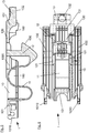
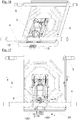
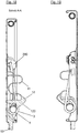
- the device 1 for securing a stepladder in a raised position as well as in the FIGS. 9 to 19 The arrangement shown can be part of a step ladder, as for example in the document DE 20 2010 002 337 U1 or in the document DE 20 2014 100 542 U1 is disclosed. Because of the basic structure of a step ladder reference is made to these documents.
- FIGS. 9 to 19 Parts shown platform 2, platform lifter 3, a traverse 4 and a rotation axis 5 are known from the documents mentioned, even if they are referred to differently in these documents.
- the Traverse 4 connects two spars of a support part of the step ladder and also has the function to support the platform 2 in the erected state of step ladder.
- the axis of rotation 5 connects two spars of a riser of step ladder.
- the platform 2 has a rectangular plate 20 and adjoining edges of the plate side walls 21, 22, 23, of which only three are shown for clarity.
- the platform is shown cut off on one side.
- Two opposite side walls 22, namely the side wall 22 and the side wall, not shown, have recesses through which the axis of rotation 5 is passed.
- the platform 2 is fixedly connected to the axis of rotation 5.
- the axis of rotation 5 is rotatably mounted in the spars of the riser.
- the axis of rotation 5 is also the axis of rotation of the platform. 2
- the side walls 21, 22, 23 are crimped at their free, not connected to the plate 20 edges.
- the platform 2 can be advantageously prepared by deep drawing and further processing steps of a steel sheet.
- ears 200 are preferably issued by punching and bending. These ears have holes in which free ends of the wire-wound platform lifter 3 are fixed. The free ends of the platform lifter 3 pass through the holes in the ears.
- the platform lifter 3 has the task to guide the platform 2 when setting up and folding the step ladder.
- the embodiment of a device 1 shown in the figures is a monolithic plastic injection molded part.
- a device could also be made of a different material and from several assembled parts.
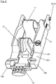
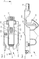
- the following range of the device 1 can be distinguished: a base body 10, a spring 11, a latch 12 and an actuating element 13.
- the main body 10 carries the spring 11, the latch 12 and the actuating element and serves to attach the device 1 to a platform 2 of the step ladder.
- the main body 10 has approximately a U-shaped shape with two legs 100 which are interconnected by a web 101.
- the legs 100 and the web define a recess in which the spring 11, the latch 12 and parts of the actuating element 13 are arranged.
- the web 101 of the main body 10 struts 1010, which serve to attach the device 1 at the bottom of the platform.
- the length of the body 10 from the free ends of the legs 100 to the struts 1010 is slightly larger than that Distance between the free, from the holes of the ears 200 projecting ends 30 of the platform lifter 3 and an inner side of a rising side side wall 23 of the platform second
- the free ends of the legs 100 between the flange and the plate 20 on the inside of the rising side side wall 23 of the platform 2 are used fitting.
- the web of the body is then pivoted against the underside of the plate 20.
- the struts 1010 of the body strike at the free ends of the platform lifter 3. Bevels on the struts thereby allow compression of the struts 1010 in the direction of the free ends of the legs.
- the free ends 30 of the platform lifter 3 slip beyond the bevels and are trapped by the undercuts adjoining the bevels, so that the stile end of the base body is also fixed.
- the spring 11 of the device adjoins an inner side of the web 101 of the base body.
- the spring 11 is a wavy curved strip which, due to its flexibility and shape, can deflect in a direction from the support member side to the riser side.
- the case 12 is arranged.
- the trap 12 has a slope 120 which is undercut.
- the trap further comprises guide elements 121. These are free in a relaxed and unassembled state of the device 1. If, on the other hand, the device 1 is mounted on the underside of the platform 2, the spring 11 is at least slightly pressed or prestressed. As a result, the guide elements 121 of the case 12 come into a space between guide surfaces 1000 of the legs 100 of the base body 10 and the underside of the plate 20, whereby the case 12 is then guided.
- the actuator 13 connects to the device.
- This actuator has a rising portion 130, a middle portion 131 and a support member side portion 132.
- the riser side portion 130 is formed flat as compared with the other two portions 131, 132.
- the middle section 131 has guide elements 1310 similar to the guide elements 121. These are at at least slightly compressed spring 11 on the guide surfaces 1001 of the legs and are guided by these guide surfaces 1001 and the underside of the plate 20 during a movement of the latch 12 and the actuating element 13.
- the support member-side end of the central portion is located under the platform 2 mounted device 1 under pressure of the spring 11 on the inside of the support member side wall 23 of the platform 2. This means that the spring 11 during assembly of the device 1 under the platform 2 compresses something becomes. Due to the bias of the spring 11 unwanted noise or wobble are avoided.
- the support member-side portion 132 of the actuator 13 has a uniform, similar to an ellipse cross-section. He passes through a recess in the support member side wall 23 of the platform 2. The section 23 can be pressed from outside the platform 2, whereby the spring 11 is further compressed. As a result, the case 12 releases the recesses 1001 in the legs 100 of the base body 10. A traverse 4 received in the recesses 1001 can then be removed from the indentations 1001 (see FIG Fig. 9 to 15 ). If, on the other hand, the actuating element 13 is not pressed in the direction of the riser part, ie the spring is only slightly compressed, the trap 12 blocks the path of a traverse 4 from the indentations.
- the slope 120 of the trap 12 Due to the slope 120 of the trap 12, it is possible when setting up the step ladder with the cross member 4 to push the case 12 in the position in which the cross member 4 can be moved into the recesses, ie when setting up the step ladder Traverse is caught in the indentations of the case 12 and the erected step ladder is secured against folding. If the step ladder to be folded, the trap 12 is then pushed back by means of the actuating element 13 against the pressure of the spring 11, whereby the indentations 1001 are released and the platform 2 can be solved by the cross member 4, which is necessary for the collapse of the step ladder ,
Landscapes
- Ladders (AREA)
Claims (12)
- Escabeau- comprenant une partie montante, qui présente deux montants et barreaux ou marches, qui sont disposés entre les montants,- comprenant une partie d'appui, qui présente deux montants, qui sont reliés l'un à l'autre par l'intermédiaire d'au moins une traverse (4), une marche ou un barreau,- dans lequel la partie montante et la partie d'appui sont reliées l'une à l'autre de manière à pouvoir pivoter,- comprenant une plate-forme (2), qui est installée de manière à pouvoir pivoter au niveau de la partie montante et qui repose sur la traverse (4) dans un état ouvert de l'échelle, et- comprenant un dispositif (1) servant à bloquer un escabeau dans une position ouverte, qui est installé sous la plate-forme (2),dans lequel le dispositif est un monolithe, caractérisé en ce que le dispositif (1) présente un corps de base (10), un pêne (12), qui peut être coulissé de manière linéaire par rapport au corps de base, et un ressort (11), qui est disposé entre le corps de base (10) et le pêne (12).
- Escabeau selon la revendication 1, caractérisé en ce que le pêne (12) n'est pas guidé par le corps de base (10) dans un état détendu du ressort (11).
- Escabeau selon la revendication 1 ou 2, caractérisé en ce que le ressort (11) présente une structure formée à la manière d'un méandre ou d'une onde.
- Escabeau selon la revendication 3, caractérisé en ce que la structure de type méandre a une épaisseur allant de 1 mm à 3 mm et une largeur allant de 10 à 50 mm, de préférence une épaisseur de 26 mm.
- Escabeau selon l'une quelconque des revendications 1 à 4, caractérisé en ce que le pêne (12) présente un chanfrein (120).
- Escabeau selon l'une quelconque des revendications 1 à 5, caractérisé en ce que le dispositif (1) présente un élément d'actionnement (13).
- Escabeau selon la revendication 6, caractérisé en ce que l'élément d'actionnement (13) est relié de manière solidaire au pêne (12).
- Escabeau selon la revendication 6 ou 7, caractérisé en ce que l'élément d'actionnement (13) dépasse du pêne (12) dans la direction de déplacement du pêne (12).
- Escabeau selon l'une quelconque des revendications 1 à 8, caractérisé en ce que le pêne (12) du dispositif (1) servant à bloquer l'escabeau dans un état ouvert vient en prise par le bas avec la traverse (4) de sorte que la traverse (4) est disposée entre le pêne (12) et la plate-forme (2).
- Escabeau selon l'une quelconque des revendications 1 à 9, caractérisé en ce que la plate-forme (2) a, dans une paroi latérale (23), sur le côté de la partie montante, un évidement, qui est traversé par l'élément d'actionnement (13).
- Escabeau selon l'une quelconque des revendications 1 à 10, caractérisé en ce que le pêne (12) est guidé entre l'au moins une surface de guidage (1000, 1001) et la plate-forme (2).
- Escabeau selon l'une quelconque des revendications 1 à 11, caractérisé en ce que le dispositif (1) est maintenu par serrage au niveau du côté inférieur de la plate-forme (2).
Applications Claiming Priority (2)
| Application Number | Priority Date | Filing Date | Title |
|---|---|---|---|
| DE202015100668.3U DE202015100668U1 (de) | 2015-02-11 | 2015-02-11 | Vorrichtung zum Sichern einer Stehleiter in einer aufgestellten Stellung |
| EP16155073.6A EP3056654B1 (fr) | 2015-02-11 | 2016-02-10 | Dispositif de securisation d'un escabeau dans une position deployee |
Related Parent Applications (1)
| Application Number | Title | Priority Date | Filing Date |
|---|---|---|---|
| EP16155073.6A Division EP3056654B1 (fr) | 2015-02-11 | 2016-02-10 | Dispositif de securisation d'un escabeau dans une position deployee |
Publications (2)
| Publication Number | Publication Date |
|---|---|
| EP3260646A1 EP3260646A1 (fr) | 2017-12-27 |
| EP3260646B1 true EP3260646B1 (fr) | 2019-09-04 |
Family
ID=55353066
Family Applications (2)
| Application Number | Title | Priority Date | Filing Date |
|---|---|---|---|
| EP17180794.4A Active EP3260646B1 (fr) | 2015-02-11 | 2016-02-10 | Escabeau comprenant un dispositif de sécurisation dans sa position déployée |
| EP16155073.6A Active EP3056654B1 (fr) | 2015-02-11 | 2016-02-10 | Dispositif de securisation d'un escabeau dans une position deployee |
Family Applications After (1)
| Application Number | Title | Priority Date | Filing Date |
|---|---|---|---|
| EP16155073.6A Active EP3056654B1 (fr) | 2015-02-11 | 2016-02-10 | Dispositif de securisation d'un escabeau dans une position deployee |
Country Status (3)
| Country | Link |
|---|---|
| EP (2) | EP3260646B1 (fr) |
| DE (1) | DE202015100668U1 (fr) |
| ES (1) | ES2643547T3 (fr) |
Families Citing this family (4)
| Publication number | Priority date | Publication date | Assignee | Title |
|---|---|---|---|---|
| US20190136621A1 (en) * | 2017-11-06 | 2019-05-09 | Jiaxing Jackson Travel Products Co., Ltd | Folding ladder |
| DE202018100133U1 (de) | 2018-01-11 | 2018-02-19 | Robert Testrut GmbH & Co. KG | Klappleiter |
| CN114466965A (zh) | 2019-09-18 | 2022-05-10 | 稳耐公司 | 人形梯枢轴和锁定机构 |
| AU2021205029B2 (en) | 2020-07-22 | 2023-04-13 | Werner Co. | Multi-Position Ladder, Method of Using and Method of Making a Multi-Position Ladder |
Family Cites Families (9)
| Publication number | Priority date | Publication date | Assignee | Title |
|---|---|---|---|---|
| AU7135500A (en) * | 1999-07-21 | 2001-02-13 | Southco, Inc. | Slide latch |
| US20060070808A1 (en) * | 2004-10-01 | 2006-04-06 | Werner Co. | Step stool latch |
| US7963369B2 (en) * | 2007-01-26 | 2011-06-21 | Werner Co. | Step stool and method |
| DE602008002812D1 (de) * | 2008-02-12 | 2010-11-11 | Lampe Holding Bv | Trittleiter |
| US20110024234A1 (en) * | 2009-07-30 | 2011-02-03 | Chen-Hsiung Lin | Ladder Chair |
| DE202010002337U1 (de) | 2010-02-12 | 2010-05-06 | Hailo-Werk Rudolf Loh Gmbh & Co. Kg | Leiter, insbesondere Stufenstehleiter oder Klapptritt, mit einer Plattform, einem Steigteil, einem Stützteil und einem Bügel |
| CN101892804B (zh) * | 2010-07-01 | 2012-08-08 | 天津市金锚集团有限责任公司 | 梯子 |
| DE202013101693U1 (de) | 2013-04-19 | 2013-04-26 | Hailo-Werk Rudolf Loh Gmbh & Co. Kg | Leiterfuß mit Rastelement |
| CN203925264U (zh) * | 2014-03-12 | 2014-11-05 | 嘉兴泰豪旅游用品有限公司 | 踏板收折式的收折梯 |
-
2015
- 2015-02-11 DE DE202015100668.3U patent/DE202015100668U1/de not_active Expired - Lifetime
-
2016
- 2016-02-10 ES ES16155073.6T patent/ES2643547T3/es active Active
- 2016-02-10 EP EP17180794.4A patent/EP3260646B1/fr active Active
- 2016-02-10 EP EP16155073.6A patent/EP3056654B1/fr active Active
Non-Patent Citations (1)
| Title |
|---|
| None * |
Also Published As
| Publication number | Publication date |
|---|---|
| ES2643547T3 (es) | 2017-11-23 |
| DE202015100668U1 (de) | 2016-05-12 |
| EP3056654A1 (fr) | 2016-08-17 |
| EP3260646A1 (fr) | 2017-12-27 |
| EP3056654B1 (fr) | 2017-08-16 |
Similar Documents
| Publication | Publication Date | Title |
|---|---|---|
| EP2851497B1 (fr) | Dispositif de montage réglable pour un élément coulissant et dispositif coulissant | |
| EP2520877A2 (fr) | Dispositif de serrage pour module PV | |
| EP3284898B1 (fr) | Joint comprenant une bande d'étanchéité pouvant s'abaisser à l'aide de deux mécanismes à ciseaux | |
| EP3260646B1 (fr) | Escabeau comprenant un dispositif de sécurisation dans sa position déployée | |
| CH716837A1 (de) | Windverband und Möbelbausatz. | |
| EP3767067B1 (fr) | Dispositif de protection de doigt côté paumelle | |
| EP2050918B1 (fr) | Joint descendant doté d'une ouverture de passage | |
| EP2721983B1 (fr) | Dispositif de support destiné à être monté sur des barres de douche | |
| EP1327783B1 (fr) | Dispositif télescopique, en particulier pour l'industrie du meuble | |
| EP2236693B1 (fr) | Support à isolation thermique pour éléments de revêtement | |
| DE202005008613U1 (de) | Teleskoprohr | |
| DE2244055C3 (de) | Handlauf für Treppengeländer | |
| EP4105432B1 (fr) | Joint d'étanchéité doté d'une bande d'étanchéité pouvant être abaissée au moyen d'un mécanisme d'abaissement actionnable à l'aide d'un déclancheur | |
| EP3279415B1 (fr) | Barre transversale | |
| DE20207715U1 (de) | Teleskopleiter | |
| EP2099989A2 (fr) | Crémone | |
| DE19501689A1 (de) | Ausziehleiter | |
| DE102008017107A1 (de) | Schlitzrinne mit Höhenverstellung | |
| EP3789573B1 (fr) | Carrosserie de véhicule | |
| EP2278089A1 (fr) | Poteau de garde-corps comprenant un profilé creux et un élément pied | |
| DE8201832U1 (de) | Falzschere für um eine waagerechte Achse schwenkbare Flügel von Fenstern, Türen und dergleichen | |
| DE102009054644A1 (de) | Beschlagteilanordnung für ein Fenster, eine Tür, eine Klappe oder dergleichen und Verfahren zum Montieren einer Bechlagteilschiene eines Fenster-, Tür- oder Klappenbeschlages bzw. dergleichen | |
| EP2896774A1 (fr) | Dispositif de fixation d'un corps de construction | |
| EP3034773B1 (fr) | Échelle ou escalier | |
| DE29907809U1 (de) | Befestigungsvorrichtung |
Legal Events
| Date | Code | Title | Description |
|---|---|---|---|
| PUAI | Public reference made under article 153(3) epc to a published international application that has entered the european phase |
Free format text: ORIGINAL CODE: 0009012 |
|
| STAA | Information on the status of an ep patent application or granted ep patent |
Free format text: STATUS: THE APPLICATION HAS BEEN PUBLISHED |
|
| AC | Divisional application: reference to earlier application |
Ref document number: 3056654 Country of ref document: EP Kind code of ref document: P |
|
| AK | Designated contracting states |
Kind code of ref document: A1 Designated state(s): AL AT BE BG CH CY CZ DE DK EE ES FI FR GB GR HR HU IE IS IT LI LT LU LV MC MK MT NL NO PL PT RO RS SE SI SK SM TR |
|
| STAA | Information on the status of an ep patent application or granted ep patent |
Free format text: STATUS: REQUEST FOR EXAMINATION WAS MADE |
|
| STAA | Information on the status of an ep patent application or granted ep patent |
Free format text: STATUS: EXAMINATION IS IN PROGRESS |
|
| 17P | Request for examination filed |
Effective date: 20180514 |
|
| RBV | Designated contracting states (corrected) |
Designated state(s): AL AT BE BG CH CY CZ DE DK EE ES FI FR GB GR HR HU IE IS IT LI LT LU LV MC MK MT NL NO PL PT RO RS SE SI SK SM TR |
|
| 17Q | First examination report despatched |
Effective date: 20180608 |
|
| GRAP | Despatch of communication of intention to grant a patent |
Free format text: ORIGINAL CODE: EPIDOSNIGR1 |
|
| STAA | Information on the status of an ep patent application or granted ep patent |
Free format text: STATUS: GRANT OF PATENT IS INTENDED |
|
| INTG | Intention to grant announced |
Effective date: 20190318 |
|
| GRAS | Grant fee paid |
Free format text: ORIGINAL CODE: EPIDOSNIGR3 |
|
| GRAA | (expected) grant |
Free format text: ORIGINAL CODE: 0009210 |
|
| STAA | Information on the status of an ep patent application or granted ep patent |
Free format text: STATUS: THE PATENT HAS BEEN GRANTED |
|
| AC | Divisional application: reference to earlier application |
Ref document number: 3056654 Country of ref document: EP Kind code of ref document: P |
|
| AK | Designated contracting states |
Kind code of ref document: B1 Designated state(s): AL AT BE BG CH CY CZ DE DK EE ES FI FR GB GR HR HU IE IS IT LI LT LU LV MC MK MT NL NO PL PT RO RS SE SI SK SM TR |
|
| REG | Reference to a national code |
Ref country code: GB Ref legal event code: FG4D Free format text: NOT ENGLISH |
|
| REG | Reference to a national code |
Ref country code: CH Ref legal event code: EP |
|
| REG | Reference to a national code |
Ref country code: AT Ref legal event code: REF Ref document number: 1175583 Country of ref document: AT Kind code of ref document: T Effective date: 20190915 |
|
| REG | Reference to a national code |
Ref country code: DE Ref legal event code: R096 Ref document number: 502016006493 Country of ref document: DE |
|
| REG | Reference to a national code |
Ref country code: IE Ref legal event code: FG4D Free format text: LANGUAGE OF EP DOCUMENT: GERMAN |
|
| REG | Reference to a national code |
Ref country code: NL Ref legal event code: FP |
|
| REG | Reference to a national code |
Ref country code: LT Ref legal event code: MG4D |
|
| PG25 | Lapsed in a contracting state [announced via postgrant information from national office to epo] |
Ref country code: BG Free format text: LAPSE BECAUSE OF FAILURE TO SUBMIT A TRANSLATION OF THE DESCRIPTION OR TO PAY THE FEE WITHIN THE PRESCRIBED TIME-LIMIT Effective date: 20191204 Ref country code: LT Free format text: LAPSE BECAUSE OF FAILURE TO SUBMIT A TRANSLATION OF THE DESCRIPTION OR TO PAY THE FEE WITHIN THE PRESCRIBED TIME-LIMIT Effective date: 20190904 Ref country code: HR Free format text: LAPSE BECAUSE OF FAILURE TO SUBMIT A TRANSLATION OF THE DESCRIPTION OR TO PAY THE FEE WITHIN THE PRESCRIBED TIME-LIMIT Effective date: 20190904 Ref country code: NO Free format text: LAPSE BECAUSE OF FAILURE TO SUBMIT A TRANSLATION OF THE DESCRIPTION OR TO PAY THE FEE WITHIN THE PRESCRIBED TIME-LIMIT Effective date: 20191204 Ref country code: FI Free format text: LAPSE BECAUSE OF FAILURE TO SUBMIT A TRANSLATION OF THE DESCRIPTION OR TO PAY THE FEE WITHIN THE PRESCRIBED TIME-LIMIT Effective date: 20190904 Ref country code: SE Free format text: LAPSE BECAUSE OF FAILURE TO SUBMIT A TRANSLATION OF THE DESCRIPTION OR TO PAY THE FEE WITHIN THE PRESCRIBED TIME-LIMIT Effective date: 20190904 |
|
| PG25 | Lapsed in a contracting state [announced via postgrant information from national office to epo] |
Ref country code: GR Free format text: LAPSE BECAUSE OF FAILURE TO SUBMIT A TRANSLATION OF THE DESCRIPTION OR TO PAY THE FEE WITHIN THE PRESCRIBED TIME-LIMIT Effective date: 20191205 Ref country code: RS Free format text: LAPSE BECAUSE OF FAILURE TO SUBMIT A TRANSLATION OF THE DESCRIPTION OR TO PAY THE FEE WITHIN THE PRESCRIBED TIME-LIMIT Effective date: 20190904 Ref country code: LV Free format text: LAPSE BECAUSE OF FAILURE TO SUBMIT A TRANSLATION OF THE DESCRIPTION OR TO PAY THE FEE WITHIN THE PRESCRIBED TIME-LIMIT Effective date: 20190904 Ref country code: AL Free format text: LAPSE BECAUSE OF FAILURE TO SUBMIT A TRANSLATION OF THE DESCRIPTION OR TO PAY THE FEE WITHIN THE PRESCRIBED TIME-LIMIT Effective date: 20190904 Ref country code: ES Free format text: LAPSE BECAUSE OF FAILURE TO SUBMIT A TRANSLATION OF THE DESCRIPTION OR TO PAY THE FEE WITHIN THE PRESCRIBED TIME-LIMIT Effective date: 20190904 |
|
| PG25 | Lapsed in a contracting state [announced via postgrant information from national office to epo] |
Ref country code: RO Free format text: LAPSE BECAUSE OF FAILURE TO SUBMIT A TRANSLATION OF THE DESCRIPTION OR TO PAY THE FEE WITHIN THE PRESCRIBED TIME-LIMIT Effective date: 20190904 Ref country code: EE Free format text: LAPSE BECAUSE OF FAILURE TO SUBMIT A TRANSLATION OF THE DESCRIPTION OR TO PAY THE FEE WITHIN THE PRESCRIBED TIME-LIMIT Effective date: 20190904 Ref country code: PT Free format text: LAPSE BECAUSE OF FAILURE TO SUBMIT A TRANSLATION OF THE DESCRIPTION OR TO PAY THE FEE WITHIN THE PRESCRIBED TIME-LIMIT Effective date: 20200106 Ref country code: PL Free format text: LAPSE BECAUSE OF FAILURE TO SUBMIT A TRANSLATION OF THE DESCRIPTION OR TO PAY THE FEE WITHIN THE PRESCRIBED TIME-LIMIT Effective date: 20190904 |
|
| PG25 | Lapsed in a contracting state [announced via postgrant information from national office to epo] |
Ref country code: CZ Free format text: LAPSE BECAUSE OF FAILURE TO SUBMIT A TRANSLATION OF THE DESCRIPTION OR TO PAY THE FEE WITHIN THE PRESCRIBED TIME-LIMIT Effective date: 20190904 Ref country code: SK Free format text: LAPSE BECAUSE OF FAILURE TO SUBMIT A TRANSLATION OF THE DESCRIPTION OR TO PAY THE FEE WITHIN THE PRESCRIBED TIME-LIMIT Effective date: 20190904 Ref country code: IS Free format text: LAPSE BECAUSE OF FAILURE TO SUBMIT A TRANSLATION OF THE DESCRIPTION OR TO PAY THE FEE WITHIN THE PRESCRIBED TIME-LIMIT Effective date: 20200224 Ref country code: SM Free format text: LAPSE BECAUSE OF FAILURE TO SUBMIT A TRANSLATION OF THE DESCRIPTION OR TO PAY THE FEE WITHIN THE PRESCRIBED TIME-LIMIT Effective date: 20190904 |
|
| REG | Reference to a national code |
Ref country code: DE Ref legal event code: R097 Ref document number: 502016006493 Country of ref document: DE |
|
| PLBE | No opposition filed within time limit |
Free format text: ORIGINAL CODE: 0009261 |
|
| STAA | Information on the status of an ep patent application or granted ep patent |
Free format text: STATUS: NO OPPOSITION FILED WITHIN TIME LIMIT |
|
| PG2D | Information on lapse in contracting state deleted |
Ref country code: IS |
|
| PG25 | Lapsed in a contracting state [announced via postgrant information from national office to epo] |
Ref country code: DK Free format text: LAPSE BECAUSE OF FAILURE TO SUBMIT A TRANSLATION OF THE DESCRIPTION OR TO PAY THE FEE WITHIN THE PRESCRIBED TIME-LIMIT Effective date: 20190904 Ref country code: IS Free format text: LAPSE BECAUSE OF FAILURE TO SUBMIT A TRANSLATION OF THE DESCRIPTION OR TO PAY THE FEE WITHIN THE PRESCRIBED TIME-LIMIT Effective date: 20200105 |
|
| 26N | No opposition filed |
Effective date: 20200605 |
|
| PG25 | Lapsed in a contracting state [announced via postgrant information from national office to epo] |
Ref country code: SI Free format text: LAPSE BECAUSE OF FAILURE TO SUBMIT A TRANSLATION OF THE DESCRIPTION OR TO PAY THE FEE WITHIN THE PRESCRIBED TIME-LIMIT Effective date: 20190904 |
|
| GBPC | Gb: european patent ceased through non-payment of renewal fee |
Effective date: 20200210 |
|
| PG25 | Lapsed in a contracting state [announced via postgrant information from national office to epo] |
Ref country code: LU Free format text: LAPSE BECAUSE OF NON-PAYMENT OF DUE FEES Effective date: 20200210 Ref country code: MC Free format text: LAPSE BECAUSE OF FAILURE TO SUBMIT A TRANSLATION OF THE DESCRIPTION OR TO PAY THE FEE WITHIN THE PRESCRIBED TIME-LIMIT Effective date: 20190904 |
|
| PG25 | Lapsed in a contracting state [announced via postgrant information from national office to epo] |
Ref country code: IE Free format text: LAPSE BECAUSE OF NON-PAYMENT OF DUE FEES Effective date: 20200210 Ref country code: GB Free format text: LAPSE BECAUSE OF NON-PAYMENT OF DUE FEES Effective date: 20200210 |
|
| PG25 | Lapsed in a contracting state [announced via postgrant information from national office to epo] |
Ref country code: TR Free format text: LAPSE BECAUSE OF FAILURE TO SUBMIT A TRANSLATION OF THE DESCRIPTION OR TO PAY THE FEE WITHIN THE PRESCRIBED TIME-LIMIT Effective date: 20190904 Ref country code: MT Free format text: LAPSE BECAUSE OF FAILURE TO SUBMIT A TRANSLATION OF THE DESCRIPTION OR TO PAY THE FEE WITHIN THE PRESCRIBED TIME-LIMIT Effective date: 20190904 Ref country code: CY Free format text: LAPSE BECAUSE OF FAILURE TO SUBMIT A TRANSLATION OF THE DESCRIPTION OR TO PAY THE FEE WITHIN THE PRESCRIBED TIME-LIMIT Effective date: 20190904 |
|
| PG25 | Lapsed in a contracting state [announced via postgrant information from national office to epo] |
Ref country code: MK Free format text: LAPSE BECAUSE OF FAILURE TO SUBMIT A TRANSLATION OF THE DESCRIPTION OR TO PAY THE FEE WITHIN THE PRESCRIBED TIME-LIMIT Effective date: 20190904 |
|
| P01 | Opt-out of the competence of the unified patent court (upc) registered |
Effective date: 20230616 |
|
| REG | Reference to a national code |
Ref country code: DE Ref legal event code: R084 Ref document number: 502016006493 Country of ref document: DE |
|
| PGFP | Annual fee paid to national office [announced via postgrant information from national office to epo] |
Ref country code: NL Payment date: 20250218 Year of fee payment: 10 |
|
| PGFP | Annual fee paid to national office [announced via postgrant information from national office to epo] |
Ref country code: DE Payment date: 20250228 Year of fee payment: 10 |
|
| PGFP | Annual fee paid to national office [announced via postgrant information from national office to epo] |
Ref country code: BE Payment date: 20250218 Year of fee payment: 10 Ref country code: CH Payment date: 20250301 Year of fee payment: 10 Ref country code: AT Payment date: 20250219 Year of fee payment: 10 |
|
| PGFP | Annual fee paid to national office [announced via postgrant information from national office to epo] |
Ref country code: FR Payment date: 20250221 Year of fee payment: 10 |
|
| PGFP | Annual fee paid to national office [announced via postgrant information from national office to epo] |
Ref country code: IT Payment date: 20250221 Year of fee payment: 10 |