EP3260697B1 - Sangle de bord arrière comprenant une fente à section transversale - Google Patents
Sangle de bord arrière comprenant une fente à section transversale Download PDFInfo
- Publication number
- EP3260697B1 EP3260697B1 EP17176048.1A EP17176048A EP3260697B1 EP 3260697 B1 EP3260697 B1 EP 3260697B1 EP 17176048 A EP17176048 A EP 17176048A EP 3260697 B1 EP3260697 B1 EP 3260697B1
- Authority
- EP
- European Patent Office
- Prior art keywords
- trailing edge
- rotor blade
- section
- shells
- chords
- Prior art date
- Legal status (The legal status is an assumption and is not a legal conclusion. Google has not performed a legal analysis and makes no representation as to the accuracy of the status listed.)
- Active
Links
Images

Classifications
-
- F—MECHANICAL ENGINEERING; LIGHTING; HEATING; WEAPONS; BLASTING
- F03—MACHINES OR ENGINES FOR LIQUIDS; WIND, SPRING, OR WEIGHT MOTORS; PRODUCING MECHANICAL POWER OR A REACTIVE PROPULSIVE THRUST, NOT OTHERWISE PROVIDED FOR
- F03D—WIND MOTORS
- F03D1/00—Wind motors with rotation axis substantially parallel to the air flow entering the rotor
- F03D1/06—Rotors
- F03D1/065—Rotors characterised by their construction elements
- F03D1/0675—Rotors characterised by their construction elements of the blades
-
- B—PERFORMING OPERATIONS; TRANSPORTING
- B29—WORKING OF PLASTICS; WORKING OF SUBSTANCES IN A PLASTIC STATE IN GENERAL
- B29C—SHAPING OR JOINING OF PLASTICS; SHAPING OF MATERIAL IN A PLASTIC STATE, NOT OTHERWISE PROVIDED FOR; AFTER-TREATMENT OF THE SHAPED PRODUCTS, e.g. REPAIRING
- B29C65/00—Joining or sealing of preformed parts, e.g. welding of plastics materials; Apparatus therefor
- B29C65/48—Joining or sealing of preformed parts, e.g. welding of plastics materials; Apparatus therefor using adhesives, i.e. using supplementary joining material; solvent bonding
- B29C65/52—Joining or sealing of preformed parts, e.g. welding of plastics materials; Apparatus therefor using adhesives, i.e. using supplementary joining material; solvent bonding characterised by the way of applying the adhesive
-
- B—PERFORMING OPERATIONS; TRANSPORTING
- B29—WORKING OF PLASTICS; WORKING OF SUBSTANCES IN A PLASTIC STATE IN GENERAL
- B29C—SHAPING OR JOINING OF PLASTICS; SHAPING OF MATERIAL IN A PLASTIC STATE, NOT OTHERWISE PROVIDED FOR; AFTER-TREATMENT OF THE SHAPED PRODUCTS, e.g. REPAIRING
- B29C66/00—General aspects of processes or apparatus for joining preformed parts
- B29C66/50—General aspects of joining tubular articles; General aspects of joining long products, i.e. bars or profiled elements; General aspects of joining single elements to tubular articles, hollow articles or bars; General aspects of joining several hollow-preforms to form hollow or tubular articles
- B29C66/51—Joining tubular articles, profiled elements or bars; Joining single elements to tubular articles, hollow articles or bars; Joining several hollow-preforms to form hollow or tubular articles
- B29C66/54—Joining several hollow-preforms, e.g. half-shells, to form hollow articles, e.g. for making balls, containers; Joining several hollow-preforms, e.g. half-cylinders, to form tubular articles
-
- B—PERFORMING OPERATIONS; TRANSPORTING
- B29—WORKING OF PLASTICS; WORKING OF SUBSTANCES IN A PLASTIC STATE IN GENERAL
- B29L—INDEXING SCHEME ASSOCIATED WITH SUBCLASS B29C, RELATING TO PARTICULAR ARTICLES
- B29L2031/00—Other particular articles
- B29L2031/08—Blades for rotors, stators, fans, turbines or the like, e.g. screw propellers
- B29L2031/082—Blades, e.g. for helicopters
- B29L2031/085—Wind turbine blades
-
- F—MECHANICAL ENGINEERING; LIGHTING; HEATING; WEAPONS; BLASTING
- F01—MACHINES OR ENGINES IN GENERAL; ENGINE PLANTS IN GENERAL; STEAM ENGINES
- F01D—NON-POSITIVE DISPLACEMENT MACHINES OR ENGINES, e.g. STEAM TURBINES
- F01D5/00—Blades; Blade-carrying members; Heating, heat-insulating, cooling or antivibration means on the blades or the members
- F01D5/12—Blades
- F01D5/14—Form or construction
- F01D5/147—Construction, i.e. structural features, e.g. of weight-saving hollow blades
-
- F—MECHANICAL ENGINEERING; LIGHTING; HEATING; WEAPONS; BLASTING
- F05—INDEXING SCHEMES RELATING TO ENGINES OR PUMPS IN VARIOUS SUBCLASSES OF CLASSES F01-F04
- F05B—INDEXING SCHEME RELATING TO WIND, SPRING, WEIGHT, INERTIA OR LIKE MOTORS, TO MACHINES OR ENGINES FOR LIQUIDS COVERED BY SUBCLASSES F03B, F03D AND F03G
- F05B2230/00—Manufacture
- F05B2230/20—Manufacture essentially without removing material
- F05B2230/23—Manufacture essentially without removing material by permanently joining parts together
-
- F—MECHANICAL ENGINEERING; LIGHTING; HEATING; WEAPONS; BLASTING
- F05—INDEXING SCHEMES RELATING TO ENGINES OR PUMPS IN VARIOUS SUBCLASSES OF CLASSES F01-F04
- F05B—INDEXING SCHEME RELATING TO WIND, SPRING, WEIGHT, INERTIA OR LIKE MOTORS, TO MACHINES OR ENGINES FOR LIQUIDS COVERED BY SUBCLASSES F03B, F03D AND F03G
- F05B2230/00—Manufacture
- F05B2230/50—Building or constructing in particular ways
-
- F—MECHANICAL ENGINEERING; LIGHTING; HEATING; WEAPONS; BLASTING
- F05—INDEXING SCHEMES RELATING TO ENGINES OR PUMPS IN VARIOUS SUBCLASSES OF CLASSES F01-F04
- F05B—INDEXING SCHEME RELATING TO WIND, SPRING, WEIGHT, INERTIA OR LIKE MOTORS, TO MACHINES OR ENGINES FOR LIQUIDS COVERED BY SUBCLASSES F03B, F03D AND F03G
- F05B2230/00—Manufacture
- F05B2230/60—Assembly methods
-
- F—MECHANICAL ENGINEERING; LIGHTING; HEATING; WEAPONS; BLASTING
- F05—INDEXING SCHEMES RELATING TO ENGINES OR PUMPS IN VARIOUS SUBCLASSES OF CLASSES F01-F04
- F05B—INDEXING SCHEME RELATING TO WIND, SPRING, WEIGHT, INERTIA OR LIKE MOTORS, TO MACHINES OR ENGINES FOR LIQUIDS COVERED BY SUBCLASSES F03B, F03D AND F03G
- F05B2240/00—Components
- F05B2240/20—Rotors
- F05B2240/30—Characteristics of rotor blades, i.e. of any element transforming dynamic fluid energy to or from rotational energy and being attached to a rotor
- F05B2240/301—Cross-section characteristics
-
- F—MECHANICAL ENGINEERING; LIGHTING; HEATING; WEAPONS; BLASTING
- F05—INDEXING SCHEMES RELATING TO ENGINES OR PUMPS IN VARIOUS SUBCLASSES OF CLASSES F01-F04
- F05B—INDEXING SCHEME RELATING TO WIND, SPRING, WEIGHT, INERTIA OR LIKE MOTORS, TO MACHINES OR ENGINES FOR LIQUIDS COVERED BY SUBCLASSES F03B, F03D AND F03G
- F05B2250/00—Geometry
- F05B2250/10—Geometry two-dimensional
- F05B2250/12—Geometry two-dimensional rectangular
-
- F—MECHANICAL ENGINEERING; LIGHTING; HEATING; WEAPONS; BLASTING
- F05—INDEXING SCHEMES RELATING TO ENGINES OR PUMPS IN VARIOUS SUBCLASSES OF CLASSES F01-F04
- F05D—INDEXING SCHEME FOR ASPECTS RELATING TO NON-POSITIVE-DISPLACEMENT MACHINES OR ENGINES, GAS-TURBINES OR JET-PROPULSION PLANTS
- F05D2230/00—Manufacture
- F05D2230/20—Manufacture essentially without removing material
- F05D2230/23—Manufacture essentially without removing material by permanently joining parts together
-
- F—MECHANICAL ENGINEERING; LIGHTING; HEATING; WEAPONS; BLASTING
- F05—INDEXING SCHEMES RELATING TO ENGINES OR PUMPS IN VARIOUS SUBCLASSES OF CLASSES F01-F04
- F05D—INDEXING SCHEME FOR ASPECTS RELATING TO NON-POSITIVE-DISPLACEMENT MACHINES OR ENGINES, GAS-TURBINES OR JET-PROPULSION PLANTS
- F05D2240/00—Components
- F05D2240/20—Rotors
- F05D2240/30—Characteristics of rotor blades, i.e. of any element transforming dynamic fluid energy to or from rotational energy and being attached to a rotor
- F05D2240/301—Cross-sectional characteristics
-
- F—MECHANICAL ENGINEERING; LIGHTING; HEATING; WEAPONS; BLASTING
- F05—INDEXING SCHEMES RELATING TO ENGINES OR PUMPS IN VARIOUS SUBCLASSES OF CLASSES F01-F04
- F05D—INDEXING SCHEME FOR ASPECTS RELATING TO NON-POSITIVE-DISPLACEMENT MACHINES OR ENGINES, GAS-TURBINES OR JET-PROPULSION PLANTS
- F05D2240/00—Components
- F05D2240/20—Rotors
- F05D2240/30—Characteristics of rotor blades, i.e. of any element transforming dynamic fluid energy to or from rotational energy and being attached to a rotor
- F05D2240/304—Characteristics of rotor blades, i.e. of any element transforming dynamic fluid energy to or from rotational energy and being attached to a rotor related to the trailing edge of a rotor blade
-
- Y—GENERAL TAGGING OF NEW TECHNOLOGICAL DEVELOPMENTS; GENERAL TAGGING OF CROSS-SECTIONAL TECHNOLOGIES SPANNING OVER SEVERAL SECTIONS OF THE IPC; TECHNICAL SUBJECTS COVERED BY FORMER USPC CROSS-REFERENCE ART COLLECTIONS [XRACs] AND DIGESTS
- Y02—TECHNOLOGIES OR APPLICATIONS FOR MITIGATION OR ADAPTATION AGAINST CLIMATE CHANGE
- Y02E—REDUCTION OF GREENHOUSE GAS [GHG] EMISSIONS, RELATED TO ENERGY GENERATION, TRANSMISSION OR DISTRIBUTION
- Y02E10/00—Energy generation through renewable energy sources
- Y02E10/70—Wind energy
- Y02E10/72—Wind turbines with rotation axis in wind direction
-
- Y—GENERAL TAGGING OF NEW TECHNOLOGICAL DEVELOPMENTS; GENERAL TAGGING OF CROSS-SECTIONAL TECHNOLOGIES SPANNING OVER SEVERAL SECTIONS OF THE IPC; TECHNICAL SUBJECTS COVERED BY FORMER USPC CROSS-REFERENCE ART COLLECTIONS [XRACs] AND DIGESTS
- Y02—TECHNOLOGIES OR APPLICATIONS FOR MITIGATION OR ADAPTATION AGAINST CLIMATE CHANGE
- Y02P—CLIMATE CHANGE MITIGATION TECHNOLOGIES IN THE PRODUCTION OR PROCESSING OF GOODS
- Y02P70/00—Climate change mitigation technologies in the production process for final industrial or consumer products
- Y02P70/50—Manufacturing or production processes characterised by the final manufactured product
Definitions
- the invention relates to a rotor blade according to claim 1 and a method for manufacturing a rotor blade according to claim 10.
- Rotor blades for wind turbines are of course well known in the prior art.
- a rotor blade that consists of a fiber composite system.
- Rotor blade half-shells are first manufactured and glued to one another.
- webs are provided between the rotor blade half-shells, which are bonded to the rotor blade half-shells via straps.
- Belts and webs form a double T-beam in cross section.
- a main chord is provided on the rotor blade half-shells, which runs essentially along the line of the greatest profile heights. The opposite main chords are connected to each other via a bridge.
- the DE 10 2014 221 966 A1 concerns rotor blades with main and trailing edge chords integrated into the rotor blade half shell.
- the U.S. 2011/0206529 A1 discloses a rotor blade with a double web formed in one piece in the interior of the rotor blade and an angled web arranged between the double web and the trailing edge of the rotor blade.
- a disadvantage of the known rotor blades is the fact that more material has to be used to form the trailing edge belt than would be necessary to meet the rigidity requirements, since this configuration, which corresponds to the prior art, tends very strongly to buckling instability when the trailing edge of the rotor blade is subjected to pressure. Therefore, additional layers of semi-finished fiber products must be introduced in order to achieve the required security against buckling. However, since the distance between the surface of the aerodynamic pressure side of the rotor blade and its aerodynamic suction side is small, the proportion of Steiner caused by each additional layer of semi-finished fiber is also small. Therefore, the effectiveness of additional layers of semi-finished fiber products in the trailing edge to increase security against buckling stability very low, and a very large additional number of layers of semi-finished fiber products is required, which makes the rotor blade unnecessarily expensive.
- the object is achieved by a rotor blade with the features of claim 1 mentioned at the outset.
- the rotor blade according to the invention has two rotor blade half-shells, each produced in a laminating process, which each have an edge that runs almost entirely around the rotor blade half-shells, along which edge the two rotor blade half-shells are glued together.
- An opening remains only at a root of the rotor blade, via which the rotor blade can be attached to a rotor hub with a connection.
- At least one trailing edge chord is arranged in each of the two half-shells.
- the trailing edge chords run along the respective trailing edge of the rotor blade half shell in a longitudinal direction, and they are rectangular in a cross section, preferably perpendicular to their longitudinal direction, at least along a section in the longitudinal direction. Rectangular here also means a substantially rectangular cross-sectional shape. The corners may be slightly rounded.
- the cross section is preferably rectangular in sections, preferably exactly rectangular. A square cross-section can also be provided.
- the rectangular cross section is designed such that the trailing edge chord has a straight inner surface pointing into the interior of the rotor blade, at least along most of its width, and a height of the rotor blade trailing edge chord is the same along this width.
- the rotor blade trailing edge chord can be bevelled, rounded or flattened at the longitudinal edges, running on the inner wall of the rotor blade, so that no sharp or sensitive edges are exposed.
- the aforementioned smooth cross sections are also referred to here as rectangular, at least as long as the straight inner surface accounts for at least half the width.
- each of the two opposite trailing edge chords has a rectangular cross-section along a section that extends in the longitudinal direction, transversely, preferably perpendicularly, to the longitudinal direction.
- the longitudinal direction is to be understood here as a longitudinal direction of the trailing edge belt along the respective section, which can be variable along the trailing edge belt and can also deviate somewhat from the longitudinal direction of the rotor blade.
- the two trailing edge straps face each other when they face each other with their wide inner sides.
- the trailing edge chord in the section in which the at least one trailing edge chord has a rectangular cross-section is further away from the trailing edge associated with it than in other sections.
- a trailing edge of the rotor blade has at most a first thickness in the section and the trailing edge chord is spaced farther from the trailing edge margin everywhere along the section than in another section where the rotor blade has a greater than the first thickness.
- the thickness is understood here as the distance between two points on the outer skin of the rotor blade perpendicular to the rotor blade chord or to the skeleton line.
- the section is to be understood here as the area in which the trailing edge belt is provided.
- the trailing edge chord is thus further spaced from its associated trailing edge where the rotor blade has a first thickness, but which is small, at least less than in other sections where the trailing edge chord runs closer to the trailing edge.
- each of the trailing edge chords is preferably spaced far enough from the trailing edge edges assigned to them that a minimum distance between the two rotor blade half shells in the area in which the trailing edge chords are located is at least 3 mm.
- the distance is understood here as the clear distance between two points on the inner skin of the rotor blade perpendicular to the rotor blade chord or to the skeleton line.
- the trailing edge chord is thus shifted at least in sections from the trailing edge in the direction of the leading edge, in order to achieve a higher area moment of inertia of the trailing edge chords with respect to the chord if the cross-sectional area of the trailing edge chord remains unchanged to a design according to the prior art.
- the trailing edge strap runs along the trailing edge. It can therefore have different distances from the trailing edge along the longitudinal direction.
- the trailing edge belt is expediently of rectangular cross-section where the trailing edge has a small thickness. It may be spaced further from the trailing edge in these sections than in other sections.
- a connection between the opposite trailing edge straps is provided by a web or stringer. This results in an arrangement that has a significantly improved ratio of the mass used to the buckling resistance achieved.
- the trailing edge chord has a significantly smaller cross-section than the main chord at the same distance from the blade root.
- the trailing edge belts are rectangular in cross-section along a portion in their longitudinal direction, although the cross-sectional area, in particular the height of the rectangle, can vary.
- the trailing edge chords which are rectangular in cross section, are no longer routed everywhere directly along the trailing edge of the rotor blade, as is known in the prior art, but have a varying and preferably greater distance from the trailing edge of the rotor blade in some sections.
- the rotor blade trailing edge belts are spaced farther from the rotor blade trailing edge than, for example, in the more spacious root region of the rotor blade.
- Defining the distance between the trailing edge chord and the trailing edge of the rotor blade is an optimization task in which the cross-sectional area of the trailing edge chord and its distance from the trailing edge of the rotor blade, which is the distance between the trailing edge straps to one another via the profile shape must be selected so that there is a minimum of the ratio of the mass used to the buckling resistance achieved.
- This greater distance from the trailing edge of the rotor blade should be made available in the aerodynamic section of the rotor blade, which is provided with a lower height of the rotor blade interior, so that the trailing edge belts do not touch each other when the rotor blade half-shells are folded together during production and an adhesive bond between the two rotor blade half-shell edges is still possible is.
- the two trailing edge straps must not collide in front of the rotor blade half-shell edges and prevent the rotor blade half-shells from completely collapsing.
- the two trailing edge chords are favorably spaced from their trailing edge edges so far that there is a minimum distance of approx. 3.0 mm and a maximum distance of approx.
- a stringer is preferably also a fiber composite component, which, however, is not rectangular in cross section like a web with a height that is many times greater than its width, but in which the height of the component is less than the width of the component.
- the height of the stringer is 2 cm to 5 cm, while the width of the stringer is about 20 cm to 30 cm.
- the height and width vary along the length of the rotor blade.
- the stringer has a trapezoidal cross section, which makes it easy to use in the manufacture of the corresponding sheet shell, e.g. B. in the infusion can be integrated.
- the two trailing edge belts of the two rotor blade half shells preferably have a width of 20 cm to 30 cm.
- the width of the trailing edge straps is essentially the same, preferably exactly the same, over the entire longitudinal extent of the trailing edge strap.
- the trailing edge belt is expediently formed from a plurality of layers of a semi-finished fiber product that are placed one above the other and/or next to one another.
- the semi-finished fiber product can be a structure made of natural, plastic, glass or carbon fibers or the like, which is impregnated with a resin and then hardens.
- the design of the rotor blade according to the invention should also include other forms of semi-finished fiber products such as prepregs and pultrudates
- the number of layers of the trailing edge belt that are stacked on top of each other is adapted to the requirements for strength and buckling resistance in the respective rotor blade section.
- the trailing edge straps preferably have a height of less than 1 cm at the root or tip ends and up to 7-10 cm at their thickest point.
- the object is achieved by a method having the features of claim 10.
- the method is particularly suitable for manufacturing one of the rotor blades mentioned above.
- Rotor blades are preferably assembled from separately manufactured components such as rotor blade half-shells, webs, stringers and belts.
- the separate components are manufactured in production forms that are individually determined for them.
- several layers for example fiber-containing layers made of glass and/or carbon fibers and/or plastics and/or also natural materials as well as foams and balsa, etc., are first placed one on top of the other and side by side.
- the layers arranged in this way form a preferably dry semi-finished product.
- the semi-finished product is impregnated with a resin system in processes such as resin injection molding (RIM process) or resin transfer molding (RTM process). After the resin system has cured, the components are glued together and the rotor blade is finished.
- RIM process resin injection molding
- RTM process resin transfer molding
- the belts are already an integral part of the rotor blade half-shells, ie are integrally produced during the manufacturing process of the rotor blade half-shells.
- they can also be subsequently glued to the insides of the rotor blade half-shells or, not belonging to the invention, can be introduced as prefabricated components during the manufacture of the rotor blade half-shells.
- the trailing edge straps expediently run as close as possible to the trailing edge of the rotor blade, in order to particularly greatly increase the rigidity in the pivoting direction.
- this gives rise to the problem that, in particular in the aerodynamic area of the rotor blade along the trailing edge of the rotor blade, there is only very little free, in particular not very high, interior space in the rotor blade.
- the rotor blade trailing edge belts according to the prior art are flattened or rounded towards the trailing edge, at least along their longitudinal side pointing towards the rotor blade trailing edge, so that they do not collide when the two rotor blade half shells are folded and glued together and prevent the rotor blade half shells from completely sticking together. In the prior art, this results in a very low, often insufficient, security against buckling, so that additional material has to be provided in the trailing edge belts, which makes the rotor blade more expensive.
- the rotor blade half-shells are manufactured in separate mold half-shells, which are arranged next to one another and can be pivoted onto one another via an articulated connection.
- This pivoting mechanism makes it possible to position the almost completely circumferential edges of the two half-shells of the rotor blade precisely one above the other and, after applying a layer of adhesive, to bond them to one another along the two edges or at least one of the two edges.
- the webs, stringers and belts are expediently also glued into the half-shells of the rotor blade.
- the method according to the invention makes use of the idea of manufacturing the trailing edge belts by preferably arranging layers exactly one on top of the other, ie fiber layers made of a wide variety of materials.
- B. is infused with a resin system, which then hardens.
- B. the use of prepregs or pultrudate conceivable.
- the result is a rectangular cross-section of the trailing edge flange, whereby the trailing edge flange naturally has to be adapted to the aerodynamic shape of the inner wall of the rotor blade along the longitudinal extent, i.e. it does not run exactly straight in the longitudinal direction in particular, but follows the trailing edge and the surface of the rotor blade in an arc, so that it penetrates the blade shell structure everywhere can be integrated.
- the trailing edge straps are at a distance from the trailing edge edge.
- a distance is understood here as a distance of a longitudinal edge of the rear edge belt adjacent to the rear edge edge from the rear edge edge, which is not zero but preferably a few centimeters. So many layers are superimposed that the trailing edge belt has a thickness of 1 cm to 10 cm, preferably up to 7 - 8 cm after the resin infusion.
- the rotor blade trailing edge belt can be designed in one piece or in several pieces, with the individual pieces then being glued to one another in the rotor blade half shells and connected to one another.
- the individual fiber layers of the rotor blade trailing edge belt preferably have the same width, so that the longitudinal edges of the fabric layers are positioned exactly one above the other, with draft angles being able to be provided.
- this rectangular shape has a higher buckling resistance, even at a greater distance from the rotor blade trailing edge, than conventional straps that run exactly along the rotor blade trailing edge and have beveled or rounded longitudinal edges.
- the inner sides of the trailing edge straps located opposite one another in the interior of the rotor blade are particularly preferably connected to stringers. Because of their greater width than webs and the preferably trapezoidal cross section, stringers are easier to implement than webs when constructing the blade shell.
- FIG. 1 a suction-side rotor blade half-shell 1 of a conventional rotor blade is shown. 1 shows an internal view of the rotor blade half-shell 1. The figures are not true to scale.
- Rotor blades are preferably assembled from separately manufactured components such as rotor blade half-shells 1, belts, webs or stringers.
- the separate components are manufactured in manufacturing forms that are individually determined for them.
- several layers for example fiber-containing layers, foams, balsa, etc., are first placed on top of one another and/or next to one another.
- the layers arranged in this way form a preferably dry semi-finished product.
- the semi-finished product lies on the inside of a production mold and is covered with a vacuum foil on the side facing away from the production mold.
- the production mold or the vacuum film has a plurality of inlet openings and outlet openings.
- the semi-finished product is impregnated with a resin system in processes such as the RIM process (resin injection molding) or the RTM process (resin transfer moulding).
- the semi-finished product is placed under vacuum under the vacuum film, ie between the inner wall of the production mold and the vacuum film, in that air is sucked out through the outlet openings.
- the liquid or viscous resin system is sucked into the semi-finished product under negative pressure and soaks the semi-finished product completely. The process is carried out until the resin system also escapes from the outlet openings.
- prepregs and/or pultrudates can also be used.
- the rotor blade half-shells 1 are manufactured individually and in one piece.
- Modern rotor blades have lengths between 40 m and 60 m and up to 75 m and even more. Manufacturing molds with corresponding lengths of up to 70 m, 75 m or even longer manufacturing molds can be provided for their production.
- a main chord 2 and a trailing edge chord 3 are glued to the inside of each of the two rotor blade half shells.
- a main chord 2 and a trailing edge chord 3 are glued to the inside of each of the two rotor blade half shells.
- an inside of one of the two rotor blade half shells of a rotor blade is shown.
- the suction-side rotor blade half-shell 1 is shown. It is also possible according to a non-claimed embodiment, the
- trailing edge belt 3 As a prefabricated component in the production of the rotor blade half shells in the corresponding production form and, if necessary, to connect it to the infusion with the other layers and materials.
- Each of the rotor blade half-shells 1 has a tip-side end 4 and a root-side end 5 as well as a leading edge 6 and a trailing edge 7.
- the corresponding nomenclature also applies to the rotor blade composed of two rotor blade shells.
- a rotor blade half-shell edge 8 is provided almost all the way around the rotor blade half-shell 1 and has a width of preferably 3 to 25 cm.
- the edge 8 runs along the rotor blade leading edge 6 around the tip-side end 4 of the rotor blade half-shell 1 and along the entire rotor blade trailing edge 7.
- the two rotor blade half-shells 1 each have the edge 8, and the rotor blade shells 1 are glued together along their two edges 8.
- the width of the edge 8 can vary in certain areas, with the transitions then preferably being continuous.
- the production molds are arranged next to one another and a folding half-mold shell can be pivoted over a fixed half-mold shell, so that after the two rotor blade half-shells have been manufactured in the two half-mold shells and hardened and, if necessary, additional components such as belts and webs have been glued in, the folding half-mold shell can be folded over the fixed-position mold can be.
- both mold half-shells can be folded simultaneously or one after the other and are folded towards one another.
- An adhesive is applied along the entire edge 8 of the rotor blade half-shell to the rotor blade half-shell produced in the position-fixed mold half-shell.
- the two half-shells 1 of the rotor blade are glued together along their two edges 8 using the adhesive.
- clamping closures can be provided on the half-shells, which generate sufficient pressure between the two half-shells 1 of the rotor blade and thus on the adhesive mass.
- the main chord 2 is laid along the line of the greatest profile thickness.
- the main chord 2 can be manufactured separately or, which is not claimed, can be integrally formed on the inside of the rotor blade half-shell 1 during the manufacturing process of the rotor blade half-shell 1 .
- the main chord 2 and the trailing edge chord 3 also have fiber layers running in a longitudinal direction L, whereby the fiber layers of the chords 2, 3, but also of the rotor blade half shells 1 or the webs can have glass fibers, carbon fibers, fibers containing plastic, natural fibers, but also other types of fibers.
- the individual fiber layers can each be formed in one piece. In the case of long belts 2 , 3 , however, it can also be expedient to manufacture the belts 2 , 3 piecemeal along the longitudinal direction L and only to assemble them in the rotor blade half shell 1 . The same applies to the other components.
- the belts 2, 3 are also saturated with resin in a vacuum infusion process, cured and then glued to the inside of the rotor blade half-shell 1 or, which is not claimed, integrally formed during the manufacturing process of the rotor blade half-shell 1.
- resin in a vacuum infusion process
- the main chord 2 serves to increase the flexural rigidity of the rotor blade in the direction of flapping.
- the trailing edge belt 3 is laid along a trailing edge edge 8a of the rotor blade half-shell.
- the trailing edge belt 3 runs directly along the trailing edge 7 at a distance of a few centimeters from the edge 8, preferably at a distance of at most three to four centimetres.
- the distance between the trailing edge belt 3 and the rotor blade half-shell trailing edge edge 8a is essentially the same over the entire length of the trailing edge belt 3 according to the prior art, but in any case is very small and is a few centimeters.
- the trailing edge chord 3 according to the invention runs along a different line in the rotor blade half shell 1 than the known trailing edge chord 3.
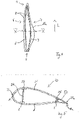
- FIG. 2 shows a cross section of a rotor blade 20 according to the prior art along a line which is approximately the height of 1 marked cross-section line II - II has. However, is in 1 only one rotor blade half-shell 1 drawn, while 2 12 shows a cross-section of the complete rotor blade 20.
- FIG. The two rotor blade half-shells 1, 21 each have an associated rotor blade half-shell edge 8a, 22a, and they are glued to one another along their rotor blade half-shell edges 8a, 22a.
- the two main belts 2, 23 are located within the rotor blade 20, approximately parallel to one another.
- the two main chords 2, 23 are bonded to one another via a web 24, which is also produced separately in a laminating process, by two adhesive connections between the longitudinal sides of the web and the inner sides of the chord.
- the web 24 has adhesive lips on its long sides, which create a larger contact surface between the main chord 2, 23 and the web 24.
- the trailing edge straps 3, 25 are arranged very close to the respective trailing edge edge 8a, 22a and are also arranged close to the respective trailing edge edge 8a, 22a of the rotor blade half shell in the longitudinal direction L in the middle, aerodynamic region of the rotor blade 20, the two trailing edge straps 3, 25 must go to the trailing edge edge 8a, 22a, so that when the two rotor blade half-shells 1, 21 are folded onto one another, the two trailing edge straps 3, 25 do not touch, in particular not before the two rotor blade half-shell trailing edges 8a, 22a, and thus make bonding impossible or at least hinder it.
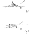
- the two trailing edge belts 3, 25 are approximately semi-lens-shaped or slightly curved inward in cross section.
- fiber layers 31 of approximately the same width, preferably exactly the same width are not placed exactly one on top of the other, but offset one on top of the other along a width B of the rotor blade 20 or the rotor blade half-shell 1, 21, so that in a middle region viewed along the width B more fiber layers are superimposed than at the longitudinal edges of the trailing edge belts 3, 25, i.e. the further one gets along the width in the direction of the leading edge 6 and the trailing edge 7, the fewer fiber layers 31 overlap each other, and thus a semi-lens-shaped cross-section is formed.
- the semi-lens-shaped form is created after infusion with the resin system, in that the fiber layers are infused with a resin system.
- FIG. 4 shows a rotor blade half-shell 1 according to the invention Fig.1, 2 , 3 What has been said can also be applied to the rotor blade 20 according to the invention, with the exception of the arrangement of the trailing edge belt 3 .
- the same reference symbols are therefore also chosen.
- the rotor blade half-shells 1, 21 themselves can be made in a conventional manufacturing process, e.g. B. are manufactured in the infusion process. Likewise, the main straps 2, 23 can be manufactured in a known manner. The position of the two trailing edge belts 3, 25 in the two rotor blade half shells 1, 21 differs from the prior art Fig.1 and Fig.2 .
- the trailing edge belt 3 according to 4 is no longer guided closely along the trailing edge edge 8a along the entire longitudinal direction L of the rotor blade half-shell 1, but it preferably has a different distance from the trailing edge edge 8a. In the aerodynamic area of the rotor blade, the distance from the trailing edge 7 is greater than in the area of the root-side end 5.
- figure 5 shows a cross section according to the invention of a rotor blade 20 according to the invention along a line which is approximately at the height V - V in figure 4 is arranged, wherein in 4 just one rotor blade half shell 1 is shown, while in figure 5 a cross section of a complete rotor blade 20 is shown.
- the two trailing edge belts 3, 25 are compared to 2 further spaced from the trailing edge edges 8a, 22a, in particular the two trailing edge belts 3, 25 are spaced so far from the rotor blade trailing edge 7 that they are rectangular in cross section, preferably exactly rectangular.
- the distance from the trailing edge of the rotor blade half-shell 8a, 22a is dimensioned such that when the two rotor blade half-shells 1, 21 are folded onto one another, despite the cross-section Due to the rectangular shape of both trailing edge straps 3, 25, the two trailing edge straps 3, 25 do not touch each other, while the two trailing edge edges 8a, 22a are so close opposite that they can be glued together.
- the two trailing edge straps 3, 25 are connected to one another with a stringer 50 via adhesive connections.
- the layer structure can be selected in a known manner, ie the type of material of the layers and the number of layers can be selected according to the prior art, such as the structure in 3 be elected. However, other layer sequences and a different number of layers can also be selected compared to the prior art. However, what is essential to the invention is that the individual layers are no longer offset but are preferably positioned exactly one above the other so that their lateral edges are arranged parallel one above the other and perpendicularly on the inside of the rotor blade half-shell 1 . As a result, in contrast to the prior art, the shape of the rear edge belts 3, 25 is essentially rectangular in cross section.
- Trailing edge chords 3, 25 with a rectangular cross-section have a higher buckling resistance with the same cross-sectional area compared to the chords with a semi-elliptical cross-section.
- the trailing edge straps 3, 25 are buckling-critical when the tip-side end 4 is bent by external forces against the direction of rotation of the rotor in the direction of the trailing edge 7 and the trailing edge 7 is thereby under a compressive load. It has been shown that with the same cross-sectional area, trailing edge straps 3, 25 with a rectangular cross section have a higher buckling resistance than trailing edge straps 3, 25 with a semi-elliptical cross section Reduce rotor blade.
Landscapes
- Engineering & Computer Science (AREA)
- Mechanical Engineering (AREA)
- Life Sciences & Earth Sciences (AREA)
- Sustainable Development (AREA)
- Sustainable Energy (AREA)
- Chemical & Material Sciences (AREA)
- Combustion & Propulsion (AREA)
- General Engineering & Computer Science (AREA)
- Wind Motors (AREA)
- Superconductors And Manufacturing Methods Therefor (AREA)
- Structure Of Belt Conveyors (AREA)
- Soil Working Implements (AREA)
Claims (10)
- Pale de rotor d'une éolienne, comprenant deux demi-coques de pale de rotor (1, 21) pourvues respectivement d'une bordure de bord d'attaque et de bord de fuite (8a, 22a) qui sont collées ensemble le long des bordures de bord d'attaque et de bord de fuite (8a, 22a), et qui présentent respectivement une membrure de bord de fuite (3, 25),
dans laquelle les deux membrures de bord de fuite (3, 25) présentent au moins le long d'une partie dans une direction longitudinale (L) une section transversale rectangulaire transversalement à la direction longitudinale (L), et les deux membrures de bord de fuite (3, 25) sont collées sur une face intérieure des demi-coques de pale de rotor (1, 21) et sont reliées l'une à l'autre par un raidisseur (50) à l'aide d'assemblages collés, et une distance de la membrure de bord de fuite (3, 25) respective dans une zone aérodynamique de la pale de rotor par rapport à la bordure de bord de fuite (8a, 22a) est supérieure à celle dans une zone d'une extrémité côté pied (5), dans laquelle la membrure de bord de fuite (3, 25) respective dans la partie dans laquelle la membrure de bord de fuite (3, 25) est façonnée de manière rectangulaire en section transversale est plus éloignée de la bordure de bord de fuite (8a, 22a) qui lui est associée que dans d'autres parties. - Pale de rotor selon la revendication 1, caractérisée en ce que les deux membrures de bord de fuite (3, 25) sont mutuellement opposées.
- Pale de rotor selon la revendication 1 ou 2, caractérisée en ce qu'un bord de fuite (7) de la pale de rotor (20) présente dans la partie au maximum une première épaisseur, et la membrure de bord de fuite (3, 25) respective est espacée le long de la partie partout plus loin des bordures de bord de fuite (8a, 22a) que dans une autre partie dans laquelle la pale de rotor (20) présente une épaisseur supérieure à la première épaisseur.
- Pale de rotor selon l'une quelconque des revendications précédentes, caractérisée en ce que chacune des membrures de bord de fuite (3, 25) est éloignée des bordures de bord de fuite (8a, 22a) qui lui sont associées à tel point qu'une distance minimale entre les deux demi-coques de pale de rotor (1, 21) mesure au moins 3 mm dans la zone dans laquelle se trouvent les membrures de bord de fuite (3, 25).
- Pale de rotor selon l'une quelconque des revendications précédentes, caractérisée en ce qu'une distance maximale entre les deux demi-coques de pale de rotor (1, 21) mesure au maximum 5 à 6 cm dans la zone dans laquelle se trouvent les membrures de bord de fuite (3, 25).
- Pale de rotor selon l'une quelconque des revendications précédentes, caractérisée en ce qu'entre des membrures de bord de fuite opposées (3, 25), le raidisseur (50) est disposé au moins par endroits en s'étendant le long de l'extension longitudinale des deux membrures de bord de fuite (3, 25).
- Pale de rotor selon l'une quelconque des revendications précédentes, caractérisée en ce que chacune des deux membrures de bord de fuite (3, 25) présente une largeur (B) de 20 cm à 40 cm, de préférence une largeur (B) de 20 cm à 30 cm.
- Pale de rotor selon l'une quelconque des revendications précédentes, caractérisée en ce que chacune des deux membrures de bord de fuite (3, 25) présente une hauteur de 1 mm à 80 mm.
- Pale de rotor selon l'une quelconque des revendications précédentes, caractérisée en ce qu'une distance maximale de chacune des deux membrures de bord de fuite (3, 25) par rapport à la bordure de bord de fuite (8a, 22a) mesure au maximum de 20 cm à 60 cm, de préférence au maximum de 30 cm à 45 cm.
- Procédé de fabrication d'une pale de rotor en ce que deux demi-coques de pale de rotor (1, 21) sont fabriquées, et le long des bordures de bord de fuite (8a, 22a) des deux demi-coques de pale de rotor (1, 21) respectivement une membrure de bord de fuite (3, 25) est posée qui est fabriquée en ce que des couches (31) de largeur identique sont superposées avec leurs bordures longitudinales, et ensuite un système de résine est infusé dans les couches (31), dans lequel, après le durcissement du système de résine, les deux membrures de bord de fuite (3, 25) sont collées sur une face intérieure des demi-coques de pale de rotor (1, 21) et reliées ensemble par un raidisseur (50), et la membrure de bord de fuite (3, 25) respective est disposée dans une zone aérodynamique de la pale de rotor à une plus grande distance de la bordure de bord de fuite (8a, 22a) que dans une zone d'une extrémité côté pied (5), et la membrure de bord de fuite (3, 25) respective dans la partie dans laquelle la membrure de bord de fuite (3, 25) est façonnée de manière rectangulaire en section transversale est plus éloignée de la bordure de bord de fuite (8a, 22a) qui lui est associée que dans d'autres parties.
Applications Claiming Priority (1)
| Application Number | Priority Date | Filing Date | Title |
|---|---|---|---|
| DE102016007675.5A DE102016007675A1 (de) | 2016-06-24 | 2016-06-24 | Hinterkantengurt mit Rechteckquerschnitt |
Publications (2)
| Publication Number | Publication Date |
|---|---|
| EP3260697A1 EP3260697A1 (fr) | 2017-12-27 |
| EP3260697B1 true EP3260697B1 (fr) | 2023-01-18 |
Family
ID=59061926
Family Applications (1)
| Application Number | Title | Priority Date | Filing Date |
|---|---|---|---|
| EP17176048.1A Active EP3260697B1 (fr) | 2016-06-24 | 2017-06-14 | Sangle de bord arrière comprenant une fente à section transversale |
Country Status (5)
| Country | Link |
|---|---|
| US (1) | US10662920B2 (fr) |
| EP (1) | EP3260697B1 (fr) |
| DE (1) | DE102016007675A1 (fr) |
| DK (1) | DK3260697T3 (fr) |
| ES (1) | ES2939168T3 (fr) |
Families Citing this family (6)
| Publication number | Priority date | Publication date | Assignee | Title |
|---|---|---|---|---|
| GB2600099A (en) * | 2020-10-16 | 2022-04-27 | Airbus Operations Ltd | Method of manufacturing aircraft aerofoil |
| DK4074493T3 (da) * | 2021-04-12 | 2025-11-24 | Lm Wind Power As | Fremgangsmåde til fremstilling af en vindmøllerotorvinge |
| JPWO2023074316A1 (fr) * | 2021-10-29 | 2023-05-04 | ||
| CN115355133B (zh) * | 2022-09-23 | 2023-06-06 | 新创碳谷集团有限公司 | 一种模块化宽梁风电叶片结构 |
| CN115977866B (zh) * | 2023-03-20 | 2023-05-23 | 新创碳谷集团有限公司 | 一种模块化风电叶片及其连接结构 |
| EP4707582A1 (fr) * | 2024-09-04 | 2026-03-11 | Nordex Energy SE & Co. KG | Capuchon de longeron, pale de rotor d'éolienne et procédé de fabrication d'un capuchon de longeron |
Citations (3)
| Publication number | Priority date | Publication date | Assignee | Title |
|---|---|---|---|---|
| US20110008175A1 (en) * | 2009-07-07 | 2011-01-13 | Nordex Energy Gmbh | Rotor blade for a wind turbine and method for its production |
| US20110206529A1 (en) * | 2010-12-10 | 2011-08-25 | General Electric Company | Spar assembly for a wind turbine rotor blade |
| DE102012019351A1 (de) * | 2012-10-02 | 2014-04-03 | Nordex Energy Gmbh | Verfahren und Positioniereinheit zum Zusammenfügen eines Windenergieanlagentorblatts |
Family Cites Families (15)
| Publication number | Priority date | Publication date | Assignee | Title |
|---|---|---|---|---|
| US4976587A (en) * | 1988-07-20 | 1990-12-11 | Dwr Wind Technologies Inc. | Composite wind turbine rotor blade and method for making same |
| NL1024463C2 (nl) * | 2003-10-06 | 2005-04-07 | Polymarin Holding B V | Rotor voor gebruik in een windturbine en werkwijze voor het maken van de rotor. |
| JP4699255B2 (ja) * | 2006-03-24 | 2011-06-08 | 三菱重工業株式会社 | 風車翼 |
| ES2372440T3 (es) * | 2007-11-09 | 2012-01-19 | Vestas Wind Systems A/S | Procedimiento para fabricar una pala de aerogenerador y uso de una esterilla estructural para reforzar una estructura de pala de aerogenerador. |
| JP2011032987A (ja) * | 2009-08-05 | 2011-02-17 | Nitto Denko Corp | 風力発電機ブレード用補強シート、風力発電機ブレードの補強構造、風力発電機および風力発電機ブレードの補強方法 |
| JP5308323B2 (ja) * | 2009-12-22 | 2013-10-09 | 三菱重工業株式会社 | 風車翼及びそれを用いた風力発電装置 |
| JP5427597B2 (ja) * | 2009-12-25 | 2014-02-26 | 三菱重工業株式会社 | 風車回転翼 |
| IN2012DN01230A (fr) * | 2009-12-25 | 2015-04-10 | Mitsubishi Heavy Ind Ltd | |
| DE102010055874B3 (de) * | 2010-12-24 | 2012-04-05 | Aerodyn Engineering Gmbh | Verfahren zur Herstellung eines Rotorblatts einer Windenergieanlage |
| DE102011003560B4 (de) * | 2011-02-03 | 2013-08-29 | Repower Systems Se | Verfahren zum Herstellen eines Faserhalbzeugs für die Herstellung eines faserverstärkten Bauteils einer Windenergieanlage, insbesondere Rotorblattgurt, sowie Faserhalbzeug und Verwendung eines Faserhalbzeugs |
| US20120027609A1 (en) * | 2011-05-17 | 2012-02-02 | Prasad Ogde | Wind turbine rotor blade with precured fiber rods and method for producing the same |
| GB2497578B (en) * | 2011-12-16 | 2015-01-14 | Vestas Wind Sys As | Wind turbine blades |
| DE102012107932C5 (de) | 2012-08-28 | 2024-01-11 | Siemens Gamesa Renewable Energy Service Gmbh | Verfahren zur Fertigung eines Rotorblattes und ein Rotorblatt einer Windenergieanlage |
| US10066600B2 (en) * | 2014-05-01 | 2018-09-04 | Tpi Composites, Inc. | Wind turbine rotor blade and method of construction |
| DE102014221966B4 (de) * | 2014-10-28 | 2018-07-12 | Senvion Gmbh | Verfahren zum Herstellen eines Rotorblatts einer Windenergieanlage |
-
2016
- 2016-06-24 DE DE102016007675.5A patent/DE102016007675A1/de not_active Withdrawn
-
2017
- 2017-06-14 EP EP17176048.1A patent/EP3260697B1/fr active Active
- 2017-06-14 ES ES17176048T patent/ES2939168T3/es active Active
- 2017-06-14 DK DK17176048.1T patent/DK3260697T3/da active
- 2017-06-23 US US15/631,146 patent/US10662920B2/en not_active Expired - Fee Related
Patent Citations (3)
| Publication number | Priority date | Publication date | Assignee | Title |
|---|---|---|---|---|
| US20110008175A1 (en) * | 2009-07-07 | 2011-01-13 | Nordex Energy Gmbh | Rotor blade for a wind turbine and method for its production |
| US20110206529A1 (en) * | 2010-12-10 | 2011-08-25 | General Electric Company | Spar assembly for a wind turbine rotor blade |
| DE102012019351A1 (de) * | 2012-10-02 | 2014-04-03 | Nordex Energy Gmbh | Verfahren und Positioniereinheit zum Zusammenfügen eines Windenergieanlagentorblatts |
Also Published As
| Publication number | Publication date |
|---|---|
| US10662920B2 (en) | 2020-05-26 |
| DK3260697T3 (da) | 2023-02-20 |
| US20180080432A1 (en) | 2018-03-22 |
| ES2939168T3 (es) | 2023-04-19 |
| DE102016007675A1 (de) | 2017-12-28 |
| EP3260697A1 (fr) | 2017-12-27 |
Similar Documents
| Publication | Publication Date | Title |
|---|---|---|
| DE102011078951B4 (de) | Verfahren zum Herstellen eines Rotorblatts für eine Windenergieanlage, Sandwich-Preform und Rotorblatt für eine Windenergieanlage | |
| EP2363599B2 (fr) | Pale de rotor pour une éolienne, éolienne et procédé de fabrication d'une pale de rotor | |
| EP3018342B1 (fr) | Procede de fabrication d'une pale de rotor d'eolienne | |
| EP2904262B1 (fr) | Composant composite pour la pale de rotor d'une éolienne | |
| EP2454472B1 (fr) | Pale de rotor d'éolienne et procédé de fabrication d'une pale de rotor d'éolienne | |
| EP3260697A1 (fr) | Sangle de bord arrière comprenant une fente à section transversale | |
| EP2181834B1 (fr) | Procédé pour la fabrication d'une semelle de longeron d'une pale d'éolienne | |
| EP3496936B1 (fr) | Semelle de longeron en éléments préfabriqués et tissu non-tissé et son procédé de production | |
| EP2666615B1 (fr) | Procédé de fabrication d'une demi-coque pour pale de rotor d'éolienne ou d'une pale de rotor d'éolienne et moule de fabrication à cette fin | |
| EP2670581B1 (fr) | Procédé, semi-produit pour la production d'un composant renforcé par des fibres d'une éolienne et utilisation du semi-produit | |
| EP3604797B1 (fr) | Bande de produit de pultrusion rétrécie et son procédé de fabrication | |
| EP3286078B1 (fr) | Élément de gouverne | |
| EP3551438B1 (fr) | Membrure de bord de fuite d'une pale de rotor d'une installation éolienne, pale de rotor et procédé de fabrication d'une membrure de bord de fuite | |
| EP3299613B1 (fr) | Pale de rotor ayant un élément de liaison d'extrémité | |
| DE102009004813B4 (de) | Faserverstärkte Kunststoffplatte mit laminiertem Buchseneinsatz | |
| EP2565463B1 (fr) | Pompe à vide | |
| DE102009056997B4 (de) | Versteifungsstruktur und Verfahren zur Herstellung einer derartigen Struktur | |
| EP3423705A1 (fr) | Dentelures à rainures de décharge | |
| EP3418040A1 (fr) | Profilé pultrudé comportant un tissu d'arrachage | |
| EP3015702B1 (fr) | Pale de rotor pour une eolienne et procede de fabrication d'une pale de rotor | |
| WO2014095856A2 (fr) | Dispositif de moulage variable pour fabriquer une demi-coque pour une pale de rotor d'éolienne | |
| DE102011077609B4 (de) | Fertigung einer Rotorblattschale | |
| DE102023126697B3 (de) | Flügel und Verfahren zu dessen Herstellung |
Legal Events
| Date | Code | Title | Description |
|---|---|---|---|
| PUAI | Public reference made under article 153(3) epc to a published international application that has entered the european phase |
Free format text: ORIGINAL CODE: 0009012 |
|
| STAA | Information on the status of an ep patent application or granted ep patent |
Free format text: STATUS: THE APPLICATION HAS BEEN PUBLISHED |
|
| AK | Designated contracting states |
Kind code of ref document: A1 Designated state(s): AL AT BE BG CH CY CZ DE DK EE ES FI FR GB GR HR HU IE IS IT LI LT LU LV MC MK MT NL NO PL PT RO RS SE SI SK SM TR |
|
| AX | Request for extension of the european patent |
Extension state: BA ME |
|
| STAA | Information on the status of an ep patent application or granted ep patent |
Free format text: STATUS: REQUEST FOR EXAMINATION WAS MADE |
|
| 17P | Request for examination filed |
Effective date: 20180627 |
|
| RBV | Designated contracting states (corrected) |
Designated state(s): AL AT BE BG CH CY CZ DE DK EE ES FI FR GB GR HR HU IE IS IT LI LT LU LV MC MK MT NL NO PL PT RO RS SE SI SK SM TR |
|
| STAA | Information on the status of an ep patent application or granted ep patent |
Free format text: STATUS: EXAMINATION IS IN PROGRESS |
|
| 17Q | First examination report despatched |
Effective date: 20200422 |
|
| RAP1 | Party data changed (applicant data changed or rights of an application transferred) |
Owner name: SIEMENS GAMESA RENEWABLE ENERGY SERVICE GMBH |
|
| GRAP | Despatch of communication of intention to grant a patent |
Free format text: ORIGINAL CODE: EPIDOSNIGR1 |
|
| STAA | Information on the status of an ep patent application or granted ep patent |
Free format text: STATUS: GRANT OF PATENT IS INTENDED |
|
| INTG | Intention to grant announced |
Effective date: 20220919 |
|
| GRAS | Grant fee paid |
Free format text: ORIGINAL CODE: EPIDOSNIGR3 |
|
| GRAA | (expected) grant |
Free format text: ORIGINAL CODE: 0009210 |
|
| STAA | Information on the status of an ep patent application or granted ep patent |
Free format text: STATUS: THE PATENT HAS BEEN GRANTED |
|
| AK | Designated contracting states |
Kind code of ref document: B1 Designated state(s): AL AT BE BG CH CY CZ DE DK EE ES FI FR GB GR HR HU IE IS IT LI LT LU LV MC MK MT NL NO PL PT RO RS SE SI SK SM TR |
|
| REG | Reference to a national code |
Ref country code: GB Ref legal event code: FG4D Free format text: NOT ENGLISH |
|
| REG | Reference to a national code |
Ref country code: DE Ref legal event code: R096 Ref document number: 502017014335 Country of ref document: DE |
|
| REG | Reference to a national code |
Ref country code: CH Ref legal event code: EP |
|
| REG | Reference to a national code |
Ref country code: AT Ref legal event code: REF Ref document number: 1544847 Country of ref document: AT Kind code of ref document: T Effective date: 20230215 Ref country code: IE Ref legal event code: FG4D Free format text: LANGUAGE OF EP DOCUMENT: GERMAN |
|
| REG | Reference to a national code |
Ref country code: DK Ref legal event code: T3 Effective date: 20230217 |
|
| REG | Reference to a national code |
Ref country code: ES Ref legal event code: FG2A Ref document number: 2939168 Country of ref document: ES Kind code of ref document: T3 Effective date: 20230419 |
|
| REG | Reference to a national code |
Ref country code: LT Ref legal event code: MG9D |
|
| REG | Reference to a national code |
Ref country code: NL Ref legal event code: MP Effective date: 20230118 |
|
| PG25 | Lapsed in a contracting state [announced via postgrant information from national office to epo] |
Ref country code: NL Free format text: LAPSE BECAUSE OF FAILURE TO SUBMIT A TRANSLATION OF THE DESCRIPTION OR TO PAY THE FEE WITHIN THE PRESCRIBED TIME-LIMIT Effective date: 20230118 |
|
| PG25 | Lapsed in a contracting state [announced via postgrant information from national office to epo] |
Ref country code: RS Free format text: LAPSE BECAUSE OF FAILURE TO SUBMIT A TRANSLATION OF THE DESCRIPTION OR TO PAY THE FEE WITHIN THE PRESCRIBED TIME-LIMIT Effective date: 20230118 Ref country code: PT Free format text: LAPSE BECAUSE OF FAILURE TO SUBMIT A TRANSLATION OF THE DESCRIPTION OR TO PAY THE FEE WITHIN THE PRESCRIBED TIME-LIMIT Effective date: 20230518 Ref country code: NO Free format text: LAPSE BECAUSE OF FAILURE TO SUBMIT A TRANSLATION OF THE DESCRIPTION OR TO PAY THE FEE WITHIN THE PRESCRIBED TIME-LIMIT Effective date: 20230418 Ref country code: LV Free format text: LAPSE BECAUSE OF FAILURE TO SUBMIT A TRANSLATION OF THE DESCRIPTION OR TO PAY THE FEE WITHIN THE PRESCRIBED TIME-LIMIT Effective date: 20230118 Ref country code: LT Free format text: LAPSE BECAUSE OF FAILURE TO SUBMIT A TRANSLATION OF THE DESCRIPTION OR TO PAY THE FEE WITHIN THE PRESCRIBED TIME-LIMIT Effective date: 20230118 Ref country code: HR Free format text: LAPSE BECAUSE OF FAILURE TO SUBMIT A TRANSLATION OF THE DESCRIPTION OR TO PAY THE FEE WITHIN THE PRESCRIBED TIME-LIMIT Effective date: 20230118 |
|
| PGFP | Annual fee paid to national office [announced via postgrant information from national office to epo] |
Ref country code: FR Payment date: 20230622 Year of fee payment: 7 Ref country code: DK Payment date: 20230621 Year of fee payment: 7 Ref country code: DE Payment date: 20230620 Year of fee payment: 7 |
|
| PG25 | Lapsed in a contracting state [announced via postgrant information from national office to epo] |
Ref country code: SE Free format text: LAPSE BECAUSE OF FAILURE TO SUBMIT A TRANSLATION OF THE DESCRIPTION OR TO PAY THE FEE WITHIN THE PRESCRIBED TIME-LIMIT Effective date: 20230118 Ref country code: PL Free format text: LAPSE BECAUSE OF FAILURE TO SUBMIT A TRANSLATION OF THE DESCRIPTION OR TO PAY THE FEE WITHIN THE PRESCRIBED TIME-LIMIT Effective date: 20230118 Ref country code: IS Free format text: LAPSE BECAUSE OF FAILURE TO SUBMIT A TRANSLATION OF THE DESCRIPTION OR TO PAY THE FEE WITHIN THE PRESCRIBED TIME-LIMIT Effective date: 20230518 Ref country code: GR Free format text: LAPSE BECAUSE OF FAILURE TO SUBMIT A TRANSLATION OF THE DESCRIPTION OR TO PAY THE FEE WITHIN THE PRESCRIBED TIME-LIMIT Effective date: 20230419 Ref country code: FI Free format text: LAPSE BECAUSE OF FAILURE TO SUBMIT A TRANSLATION OF THE DESCRIPTION OR TO PAY THE FEE WITHIN THE PRESCRIBED TIME-LIMIT Effective date: 20230118 |
|
| REG | Reference to a national code |
Ref country code: DE Ref legal event code: R097 Ref document number: 502017014335 Country of ref document: DE |
|
| PG25 | Lapsed in a contracting state [announced via postgrant information from national office to epo] |
Ref country code: SM Free format text: LAPSE BECAUSE OF FAILURE TO SUBMIT A TRANSLATION OF THE DESCRIPTION OR TO PAY THE FEE WITHIN THE PRESCRIBED TIME-LIMIT Effective date: 20230118 Ref country code: RO Free format text: LAPSE BECAUSE OF FAILURE TO SUBMIT A TRANSLATION OF THE DESCRIPTION OR TO PAY THE FEE WITHIN THE PRESCRIBED TIME-LIMIT Effective date: 20230118 Ref country code: EE Free format text: LAPSE BECAUSE OF FAILURE TO SUBMIT A TRANSLATION OF THE DESCRIPTION OR TO PAY THE FEE WITHIN THE PRESCRIBED TIME-LIMIT Effective date: 20230118 Ref country code: CZ Free format text: LAPSE BECAUSE OF FAILURE TO SUBMIT A TRANSLATION OF THE DESCRIPTION OR TO PAY THE FEE WITHIN THE PRESCRIBED TIME-LIMIT Effective date: 20230118 |
|
| PGFP | Annual fee paid to national office [announced via postgrant information from national office to epo] |
Ref country code: GB Payment date: 20230622 Year of fee payment: 7 Ref country code: ES Payment date: 20230719 Year of fee payment: 7 |
|
| PLBE | No opposition filed within time limit |
Free format text: ORIGINAL CODE: 0009261 |
|
| STAA | Information on the status of an ep patent application or granted ep patent |
Free format text: STATUS: NO OPPOSITION FILED WITHIN TIME LIMIT |
|
| PG25 | Lapsed in a contracting state [announced via postgrant information from national office to epo] |
Ref country code: SK Free format text: LAPSE BECAUSE OF FAILURE TO SUBMIT A TRANSLATION OF THE DESCRIPTION OR TO PAY THE FEE WITHIN THE PRESCRIBED TIME-LIMIT Effective date: 20230118 |
|
| 26N | No opposition filed |
Effective date: 20231019 |
|
| PG25 | Lapsed in a contracting state [announced via postgrant information from national office to epo] |
Ref country code: MC Free format text: LAPSE BECAUSE OF FAILURE TO SUBMIT A TRANSLATION OF THE DESCRIPTION OR TO PAY THE FEE WITHIN THE PRESCRIBED TIME-LIMIT Effective date: 20230118 |
|
| PG25 | Lapsed in a contracting state [announced via postgrant information from national office to epo] |
Ref country code: SI Free format text: LAPSE BECAUSE OF FAILURE TO SUBMIT A TRANSLATION OF THE DESCRIPTION OR TO PAY THE FEE WITHIN THE PRESCRIBED TIME-LIMIT Effective date: 20230118 Ref country code: MC Free format text: LAPSE BECAUSE OF FAILURE TO SUBMIT A TRANSLATION OF THE DESCRIPTION OR TO PAY THE FEE WITHIN THE PRESCRIBED TIME-LIMIT Effective date: 20230118 |
|
| REG | Reference to a national code |
Ref country code: CH Ref legal event code: PL |
|
| REG | Reference to a national code |
Ref country code: BE Ref legal event code: MM Effective date: 20230630 |
|
| PG25 | Lapsed in a contracting state [announced via postgrant information from national office to epo] |
Ref country code: LU Free format text: LAPSE BECAUSE OF NON-PAYMENT OF DUE FEES Effective date: 20230614 |
|
| REG | Reference to a national code |
Ref country code: IE Ref legal event code: MM4A |
|
| PG25 | Lapsed in a contracting state [announced via postgrant information from national office to epo] |
Ref country code: LU Free format text: LAPSE BECAUSE OF NON-PAYMENT OF DUE FEES Effective date: 20230614 |
|
| PG25 | Lapsed in a contracting state [announced via postgrant information from national office to epo] |
Ref country code: IE Free format text: LAPSE BECAUSE OF NON-PAYMENT OF DUE FEES Effective date: 20230614 |
|
| PG25 | Lapsed in a contracting state [announced via postgrant information from national office to epo] |
Ref country code: IE Free format text: LAPSE BECAUSE OF NON-PAYMENT OF DUE FEES Effective date: 20230614 Ref country code: CH Free format text: LAPSE BECAUSE OF NON-PAYMENT OF DUE FEES Effective date: 20230630 |
|
| PG25 | Lapsed in a contracting state [announced via postgrant information from national office to epo] |
Ref country code: IT Free format text: LAPSE BECAUSE OF FAILURE TO SUBMIT A TRANSLATION OF THE DESCRIPTION OR TO PAY THE FEE WITHIN THE PRESCRIBED TIME-LIMIT Effective date: 20230118 Ref country code: BE Free format text: LAPSE BECAUSE OF NON-PAYMENT OF DUE FEES Effective date: 20230630 |
|
| REG | Reference to a national code |
Ref country code: AT Ref legal event code: MM01 Ref document number: 1544847 Country of ref document: AT Kind code of ref document: T Effective date: 20230614 |
|
| PG25 | Lapsed in a contracting state [announced via postgrant information from national office to epo] |
Ref country code: AT Free format text: LAPSE BECAUSE OF NON-PAYMENT OF DUE FEES Effective date: 20230614 |
|
| PG25 | Lapsed in a contracting state [announced via postgrant information from national office to epo] |
Ref country code: AT Free format text: LAPSE BECAUSE OF NON-PAYMENT OF DUE FEES Effective date: 20230614 |
|
| PG25 | Lapsed in a contracting state [announced via postgrant information from national office to epo] |
Ref country code: BG Free format text: LAPSE BECAUSE OF FAILURE TO SUBMIT A TRANSLATION OF THE DESCRIPTION OR TO PAY THE FEE WITHIN THE PRESCRIBED TIME-LIMIT Effective date: 20230118 |
|
| PG25 | Lapsed in a contracting state [announced via postgrant information from national office to epo] |
Ref country code: BG Free format text: LAPSE BECAUSE OF FAILURE TO SUBMIT A TRANSLATION OF THE DESCRIPTION OR TO PAY THE FEE WITHIN THE PRESCRIBED TIME-LIMIT Effective date: 20230118 |
|
| REG | Reference to a national code |
Ref country code: DE Ref legal event code: R119 Ref document number: 502017014335 Country of ref document: DE |
|
| REG | Reference to a national code |
Ref country code: DK Ref legal event code: EBP Effective date: 20240630 |
|
| GBPC | Gb: european patent ceased through non-payment of renewal fee |
Effective date: 20240614 |
|
| PG25 | Lapsed in a contracting state [announced via postgrant information from national office to epo] |
Ref country code: DE Free format text: LAPSE BECAUSE OF NON-PAYMENT OF DUE FEES Effective date: 20250101 |
|
| PG25 | Lapsed in a contracting state [announced via postgrant information from national office to epo] |
Ref country code: FR Free format text: LAPSE BECAUSE OF NON-PAYMENT OF DUE FEES Effective date: 20240630 |
|
| PG25 | Lapsed in a contracting state [announced via postgrant information from national office to epo] |
Ref country code: GB Free format text: LAPSE BECAUSE OF NON-PAYMENT OF DUE FEES Effective date: 20240614 |
|
| PG25 | Lapsed in a contracting state [announced via postgrant information from national office to epo] |
Ref country code: DK Free format text: LAPSE BECAUSE OF NON-PAYMENT OF DUE FEES Effective date: 20240630 |
|
| PG25 | Lapsed in a contracting state [announced via postgrant information from national office to epo] |
Ref country code: CY Free format text: LAPSE BECAUSE OF FAILURE TO SUBMIT A TRANSLATION OF THE DESCRIPTION OR TO PAY THE FEE WITHIN THE PRESCRIBED TIME-LIMIT; INVALID AB INITIO Effective date: 20170614 |
|
| REG | Reference to a national code |
Ref country code: ES Ref legal event code: FD2A Effective date: 20250731 |
|
| PG25 | Lapsed in a contracting state [announced via postgrant information from national office to epo] |
Ref country code: HU Free format text: LAPSE BECAUSE OF FAILURE TO SUBMIT A TRANSLATION OF THE DESCRIPTION OR TO PAY THE FEE WITHIN THE PRESCRIBED TIME-LIMIT; INVALID AB INITIO Effective date: 20170614 |
|
| PG25 | Lapsed in a contracting state [announced via postgrant information from national office to epo] |
Ref country code: ES Free format text: LAPSE BECAUSE OF NON-PAYMENT OF DUE FEES Effective date: 20240615 |
|
| PG25 | Lapsed in a contracting state [announced via postgrant information from national office to epo] |
Ref country code: TR Free format text: LAPSE BECAUSE OF FAILURE TO SUBMIT A TRANSLATION OF THE DESCRIPTION OR TO PAY THE FEE WITHIN THE PRESCRIBED TIME-LIMIT Effective date: 20230118 |