EP3260711B1 - Pièce de fixation - Google Patents
Pièce de fixation Download PDFInfo
- Publication number
- EP3260711B1 EP3260711B1 EP17177245.2A EP17177245A EP3260711B1 EP 3260711 B1 EP3260711 B1 EP 3260711B1 EP 17177245 A EP17177245 A EP 17177245A EP 3260711 B1 EP3260711 B1 EP 3260711B1
- Authority
- EP
- European Patent Office
- Prior art keywords
- shank
- sleeve
- head
- fastener
- elongate
- Prior art date
- Legal status (The legal status is an assumption and is not a legal conclusion. Google has not performed a legal analysis and makes no representation as to the accuracy of the status listed.)
- Active
Links
Images


Classifications
-
- F—MECHANICAL ENGINEERING; LIGHTING; HEATING; WEAPONS; BLASTING
- F16—ENGINEERING ELEMENTS AND UNITS; GENERAL MEASURES FOR PRODUCING AND MAINTAINING EFFECTIVE FUNCTIONING OF MACHINES OR INSTALLATIONS; THERMAL INSULATION IN GENERAL
- F16B—DEVICES FOR FASTENING OR SECURING CONSTRUCTIONAL ELEMENTS OR MACHINE PARTS TOGETHER, e.g. NAILS, BOLTS, CIRCLIPS, CLAMPS, CLIPS OR WEDGES; JOINTS OR JOINTING
- F16B35/00—Screw-bolts; Stay-bolts; Screw-threaded studs; Screws; Set screws
- F16B35/04—Screw-bolts; Stay-bolts; Screw-threaded studs; Screws; Set screws with specially-shaped head or shaft in order to fix the bolt on or in an object
- F16B35/06—Specially-shaped heads
-
- F—MECHANICAL ENGINEERING; LIGHTING; HEATING; WEAPONS; BLASTING
- F16—ENGINEERING ELEMENTS AND UNITS; GENERAL MEASURES FOR PRODUCING AND MAINTAINING EFFECTIVE FUNCTIONING OF MACHINES OR INSTALLATIONS; THERMAL INSULATION IN GENERAL
- F16B—DEVICES FOR FASTENING OR SECURING CONSTRUCTIONAL ELEMENTS OR MACHINE PARTS TOGETHER, e.g. NAILS, BOLTS, CIRCLIPS, CLAMPS, CLIPS OR WEDGES; JOINTS OR JOINTING
- F16B13/00—Dowels or other devices fastened in walls or the like by inserting them in holes made therein for that purpose
- F16B13/04—Dowels or other devices fastened in walls or the like by inserting them in holes made therein for that purpose with parts gripping in the hole or behind the reverse side of the wall after inserting from the front
- F16B13/08—Dowels or other devices fastened in walls or the like by inserting them in holes made therein for that purpose with parts gripping in the hole or behind the reverse side of the wall after inserting from the front with separate or non-separate gripping parts moved into their final position in relation to the body of the device without further manual operation
- F16B13/0808—Dowels or other devices fastened in walls or the like by inserting them in holes made therein for that purpose with parts gripping in the hole or behind the reverse side of the wall after inserting from the front with separate or non-separate gripping parts moved into their final position in relation to the body of the device without further manual operation by a toggle-mechanism
-
- F—MECHANICAL ENGINEERING; LIGHTING; HEATING; WEAPONS; BLASTING
- F16—ENGINEERING ELEMENTS AND UNITS; GENERAL MEASURES FOR PRODUCING AND MAINTAINING EFFECTIVE FUNCTIONING OF MACHINES OR INSTALLATIONS; THERMAL INSULATION IN GENERAL
- F16B—DEVICES FOR FASTENING OR SECURING CONSTRUCTIONAL ELEMENTS OR MACHINE PARTS TOGETHER, e.g. NAILS, BOLTS, CIRCLIPS, CLAMPS, CLIPS OR WEDGES; JOINTS OR JOINTING
- F16B37/00—Nuts or like thread-engaging members
- F16B37/12—Nuts or like thread-engaging members with thread-engaging surfaces formed by inserted coil-springs, discs, or the like; Independent pieces of wound wire used as nuts; Threaded inserts for holes
Definitions
- the present invention is related generally to fasteners such as may be used, for example, for attaching deck panels to trusses to form platforms or for mounting a wheel to an automobile or for various other uses. More particularly, the present invention is related to a type of fastener wherein the fastener head (or what might be called a nut or wing nut) is held non-detachably to the shank and is collapsible so that the shank may be received in a part for attachment thereof to another part and so as to allow quick connect as well as quick release of the part.
- the fastener head or what might be called a nut or wing nut
- U.S. patent 5,897,300 discloses a quick-release bolt securing two parts of a pump housing. It includes a threaded end and a slotted end. A release/lock plate is pivotally attached to the bolt within the slot by a pin which is attached to the bolt. A ball is spring loaded to engage lock detents or release detents to orient the plate.
- a threaded end of each bolt engages threads in each lug on a first housing half and the plate is placed in the releasing position.
- the second housing half is mated with the first housing half such that the bolts pass through the lugs thereof.
- the bolts are then tightened until the plate contacts the lugs on the second housing half.
- the bolts need be rotated only about one-half to one-quarter of a turn in order to allow the user to pivot the plate into the releasing position.
- This fastener does not suitably allow the secure attachment of a deck panel to a part located some distance below the deck panel.
- United Kingdom patent application number GB 2 119 748 discloses a pipe lifting device comprising a pin having a shaft portion which fits though a ole in the pipe and a gravity-operated latch, such as a toggle, which operated automatically when the pint is inserted through the hole and prevents unintentional withdrawal of the pin from the hole.
- Embodiments of the present invention provide a fastener as set out in the appended claims.
- Embodiments of the present invention advantageously provide a spring-loaded fastener wherein a nut or head thereof is convertible between a use position for attachment of one part to another part to which the fastener is attached and a collapsed position for detachment of the one part, with the fastener remaining attached to the other part whereby the attachment and detachment can be conducted quickly and without inadvertent dropping of fasteners or fastener parts by workers.
- FIGS. 1 to 5 there is shown generally at 20 a bolt or fastener whose parts are composed, unless otherwise specified, of stainless steel or other suitable steel or metal or material, and which includes an elongate shank 22 the lower end portion 24 of which is has screw threads 26 and the upper end portion 28 of which is fitted with an elongate head 30 or what may be called a wing nut or nut.
- the terms "upper” and “lower” and similar terms are intended, for the purposes of this specification and the claims, to be relative terms for ease of description, with the fastener 20 being arbitrarily assigned one or the lower end portion 24 to be threaded (or which in an embodiment may not be threaded) and the opposite or the upper end portion 28 to have the head 30.
- end portion 24 may be geographically above the end portion 28, it would still be referred to herein, in accordance with their meanings herein as being relative to each other, as the lower end portion.
- the parts to be attached were side-by-side, the end portions 24 and 28 would still be defined as lower and upper end portions respectively.
- a lower part, as used herein and in the claims is one to which the lower end portion 24 is attached, and an upper part, as used herein and in the claims, is one to which the upper end portion 28 is attached.
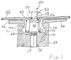
- the fastener 20 is illustrated in FIG. 1 attaching a deck panel 32 to a connector 34 which joins the ends of two trusses 36 for forming a platform. It should be understood that the fastener 20 may instead attach the deck panel 32 directly to a truss 36.
- An internally threaded member 38 which is tubular and whose outer surface may be six-sided for purposes of stability or otherwise suitably shaped, is suitably positioned within a voided space of and suitably welded to the connector 34.
- the shank 22 passes through a tubular member 42 (as described hereinafter in greater detail) which serves as an hereinafter discussed spring housing and which rests on the surface 41 of connector 34 and is welded, as by welds 44, or otherwise suitably attached to the connector 34.
- the lower end portion of the shank 22 passes downwardly through the voided space, and threads 26 on the lower end portion of the shank 22 threadedly engage the internally threaded member 38.
- the surface 41 is below the upper surface of the trusses 36 on which the deck panels 32 lie by a distance illustrated at 40.
- the tubular member height, illustrated at 46 is substantially equal to the height 40, for example, about 2.9cm (1 1/8 inch).
- the shank 22 is snugly received but freely movable within and extends beyond the lower end of a sleeve 50, whose purpose will be described in greater detail hereinafter, and the sleeve is in turn received in tubular member 42, as discussed in greater detail hereinafter.
- the head or wing nut 30 is in what might be called a use position or the attachment state wherein it may be said to extend normal to the shank 22 and is seen in FIG. 1 in this use position attaching the deck panel 32 to the trusses 36.
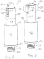
- the head 30 may be said to extend longitudinally of the shank 22 and thus substantially within the diameter of the sleeve 50.
- Holes, illustrated at 56 (one shown), in the deck panel 32 each has a diameter, illustrated at 58, which is slightly larger than the diameter 54 of the sleeve 50 but less than the diameter, illustrated at 60, of the tubular member 42.
- the deck panel 32 may be laid over the trusses 36 with the sleeve 50 received in the respective hole 56 and with the deck panel 32 stably and securely overlying and supported by the tubular member 42, as illustrated in FIG. 1 .
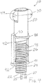
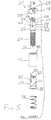
- the head 30 may then be rotated 90 degrees to the use position of FIGS. 1 , 3 , and 4 , as hereinafter discussed, and suitable tightening applied to firmly connect the deck panel 32 to the trusses 36.
- the sleeve diameter 54 may be about 1.6cm (5/8 inch)
- the tubular member diameter 60 may be about 2.2cm (7/8 inch)
- the head width (maximum, centrally thereof) 48 may be about 1.6cm (5/8 inch)
- the head length 49 may be about 2.9cm (1 1/8 inch)
- the head thickness 51 may be about 0.6cm (1/4 inch)
- the shank diameter 52 may be about 1.3cm (1 ⁇ 2 inch)
- the slot depth 23 may be about 2.5cm (1 inch), but it if of course to be understood that fasteners 20 for the same panel hole diameter 58 may have other suitable dimensions.
- the head 30 is returned to the collapsed position or original state of FIG. 2 , as hereinafter discussed, after which the deck panel 32 may be lifted off of the sleeve 50 and away, with the sleeve remaining welded or otherwise suitably attached to the framework or truss connector 34 (or, if desired, to a truss) and with the threads 26 of the lower end portion of the shank 22 remaining threadedly engaged with the framework member 38.
- the fastener 20 nor a nut is susceptible to being dropped by a worker.
- the threads 26 on the lower end portion 24 of the shank 22 constitute one embodiment of means for threadedly attaching said lower end portion 24 of said shank 22 to the lower part or member 38.
- Another embodiment of means for threadedly attaching said lower end portion 24 of said shank 22 to the lower part is illustrated in FIGS. 9, 10 , 11 , and 13 wherein, as described in greater detail hereinafter, the lower end of a shank is welded or otherwise suitably attached to a tubular member which is in turn threadedly engaged to a lower part.
- the term "means for threadedly attaching said lower end portion of said shank to the lower part" is accordingly meant, as may be used herein and in the claims, to include each of these embodiments as well as any and all equivalents thereof.
- the shank 22 has a slot, illustrated at 62, in its upper end and extending radially entirely across the shank 22 and longitudinally of the shank 22 downwardly to define a slot depth, illustrated at 23 ( FIG. 5 ), and dividing the upper end portion 28 of the shank 22 into two facing sections 64.
- the shank 22 has a longitudinal axis, illustrated at 25 ( FIG. 4 ), and, for the purposes of this specification and the claims, the radial direction, illustrated at 27, is a direction normal to the longitudinal axis 25, and the longitudinal direction, illustrated at 29, is a direction along or parallel to the longitudinal axis 25.
- a similarly sized aperture, illustrated at 68 is received centrally in the head 30, through the thickness thereof.
- a suitable pin 70 is received in the three apertures 66 and 68 thereby attaching the head 30 to the shank 22 so that the head 30 is rotatable relative to the upper end of the shank 22, with the slot 62 sized to receive the head 30 to allow such rotation.
- the head or nut 30 is thus rotatable about the pin 70 between the use position or attachment state of FIGS. 1 , 3 , and 4 and the collapsed position or original state of FIG. 2 . It is considered preferred that the head 30, as shown, be rotatable throughout 360 degrees.
- the head or nut 30 has a preferred shape to enable it to be manipulated by a preferred tool, as discussed hereinafter with respect to FIGS. 6, 7, and 8 .
- the head 30 preferably has semi-oval-shaped end portions 72 connected by an increased width central portion which defines the head width 48 and which defines block portions 74.
- each block portion 74 has a width, illustrated at 78, of for example about 0.2cm (1/16 inch) thereby defining each semi-oval portion width (adjacent the block portions 74), illustrated at 80, of for example about 1.3cm (1 ⁇ 2 inch) .
- the semi-oval portions 72 are shown in FIGS. 1 to 11 to be identical or substantially similar, in accordance with an alternative embodiment, one may be longer than the other, as will be discussed hereinafter with respect to FIGS. 12 and 13 .
- the shank 22 is received in the sleeve 50 which is spring-bias engaged to the tubular member 42 as follows.
- the sleeve 50 has a pair of diametrically opposed slots, illustrated at 82, in the upper end of its wall which correspond to the slot 62 in the shank 22.
- the width 80 of each of the head semi-oval portions 72 is less than the inner diameter, illustrated at 86, of the sleeve 50 so that a semi-oval portion may be received within the sleeve 50, as seen in FIG. 2 .
- the length, illustrated at 84, of each of the block portions 76 is also less than the inner diameter 86 of the sleeve 50 so that a block portion 74 may also be received within the sleeve 50, as seen in FIG. 3 .
- the sleeve inner diameter 86 may be about 1.3cm (1 ⁇ 2 inch) but slightly larger than the shank diameter 52 to snugly but not tightly engage the shank 22, each block portion length 84 may be about 1.1cm (7/16 inch), and each semi-oval portion width 80 may be about 2.2cm (7/8 inch).
- the block portions 74 are received in the sleeve slots 82 so that the sleeve 50 and shank 22 are locked together to rotate together.
- the sleeve 50 and shank 22 rotate together during threading and unthreading.
- the sleeve lower end is outwardly flanged as by flange 88.
- the upper end of the tubular member or spring housing 42 is inwardly flanged as by flange 90 so that the inner diameter of the flange 90 is slightly less (for example, by less than about 0.08cm (1/32 inch)) than the sleeve outer diameter 54 thus "trapping" the sleeve flange 88 within the spring housing 42 for movement upwardly and downwardly therein.
- the lower end of the tubular member or spring housing 42 is inwardly flanged as by flange 92 to thereby prevent movement of the lower end of the sleeve 50 beyond the lower end of the spring housing 42.
- a washer-shaped plate 94 is welded, such as by a pair of spot welds 96 ( FIG. 1 ), or otherwise suitably attached to the lower end of the tubular member 42. It is this plate 94 that is welded as by weld or welds 44 or otherwise suitably attached to the connector 34 or other platform frame member.
- a suitable spring 98 is received within the spring housing 42 between the sleeve flange 88 and the lower spring housing flange 92 to spring-bias the sleeve 50 upwardly.
- the pin 70 is preferably tubular, having a cylindrical wall thickness of, for example, about 0.08cm (1/32 inch). It is preferably fixedly mounted non-rotatably within the apertures 66 such as, for example, by welding or by other suitable means, and the diameter of the aperture 68 is slightly larger than the pin diameter so that head or nut 30 is snugly but freely rotatable about the pin 70.
- the shank 22 initially may be said to move downwardly relative to the sleeve 50 (or the sleeve 50 may be said to move upwardly relative to the shank 22) until the attachment of the pin 70 in the apertures 66 is completely covered to thereby protect the attachment of the pin 70 in the apertures 66 from debris.
- the shank 22 and sleeve 50 will begin moving downwardly together with the spring 98 being progressively compressed, making it harder and harder to push the sleeve 50 against the resistance of the spring 98 as the shank 22 is progressively tightened.
- the tightening may desirably continue until the distance, illustrated at 100 in FIG.
- between the nut 30 and the tubular member is equal to about the panel thickness, which may, for example, be about 0.2-0.4cm (1/16 to 1/8 inch).
- the attachment of the pin 70 in the apertures 66 may remain covered as long as the distance 100 between the nut 30 and the tubular member is less than, for example, about 1.9cm (3/4 inch), as seen in FIG. 3 . In order to continuously seal or protect the attachment of the pin 70 from debris, it is thus considered desirable that this distance 100 remain small enough, such as shown in FIG.
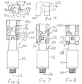
- a tool illustrated at 102 in FIGS. 6, 7, and 8 , is preferably used, as described hereinafter. Starting with the head or nut 30 in the use position of FIG. 4 , the nut 30 may be rotated to further threadedly engage the threaded member 38 and to effect tightening of the fastener 20 to the position shown in FIG. 1 .
- the shank 22 is loosened to such an extent that the sleeve 50 can be pushed downwardly by hand against the spring force, thus substantially uncovering the slot 62 at least enough so that the nut 30 can be rotated to the collapsed position (original state).
- the sleeve 50 can again be pushed downwardly against the spring force, thus again substantially uncovering the slot 62 at least enough so that the nut 30 can be rotated back to the use position (attachment state) and the shank thereafter tightened to effect a secure attachment of the panel, with the nut 30 again being prevented from movement back to the collapsed position and the sleeve 50 normally prevented from being pushed downwardly enough to effect uncovering of the slot 62.
- the nut 30 cannot be rotated back to the collapsed position until there has been enough loosening of the shank 22 to allow sufficient downward movement of the sleeve 50 to uncover the shank slot 62.
- a worker may use his or her hands to push downwardly on the sleeve 50 to clear or substantially uncover the slot 62 for movement of the nut 30 to the collapsed position and removal of the panel 32
- a suitable tool may be designed to more easily achieve such movement or to be able to apply greater force so that the distance 100 may be even further minimized for even more quickly moving the nut 30 to the original state and detaching a panel 32.
- Such a tool may be constructed using similar principles as used for the hereinafter described tool 102 as well as principles commonly known to those of ordinary skill in the art to which the present invention pertains.
- a worker may use his or her hands to quickly and easily move the sleeve 50 downwardly to move the nut 30 from the original to the attachment state after the shank 22 has been substantially threadedly received in the connector 34.
- FIGS. 6, 7, and 8 there is shown generally at 102 a tool for quickly and easily moving the nut 30 from the original to the attachment shape for attachment of a panel, with the fastener 20 initially threaded to an even greater extent than if the one's hands were used alone to so move the nut 30.
- the tool 102 which may be composed of a single molded piece of suitable hard strong plastic or composed of other suitable material, has a cylindrical longitudinal outer surface 104, a longitudinal bore, illustrated at 106, sized for passage of the shank 22 and having a surface, and a counterbore, illustrated at 108, defining a circular surface 110 for engaging the upper end of the sleeve 50. While not shown, there is desirably a slope from the surface 110 to the end of the tool 102 to alleviate any interference between the wall of the sleeve 50 and the tool and to thusly allow ease of insertion of the sleeve 50 for its end to be engaged by the tool surface 110.
- a pair of diametrically opposed slots, illustrated at 112 are provided to accommodate the opposite end portions respectively of the nut or head 30.
- the tool 102 has a portion, illustrated schematically at 114, which protrudes or juts inwardly from the bore surface 106 at a location near the end of one of the slots 112.
- This protruding portion 114 has a suitably sloping surface, illustrated schematically at 116, for suitably engaging the suitably curved surface of the respective end portion of the nut 30, as illustrated in FIG. 7 .
- Suitable shapes of the surface 116 and the nut surface can be determined using principles commonly known to those of ordinary skill in the art to which the present invention pertains.
- the jutting or trigger portion 114 may be located at a distance of, for example, about 1.9cm (3/4 inch) from the tool end, illustrated at 118.
- the specific location of the jutting or trigger portion 114 can be determined using principles commonly known to those of ordinary skill in the art to which the present invention pertains.
- the tool 102 may then be removed. Since a worker can apply greater force with the tool 102 than with his or her hands alone, the tool 102 desirably allows the fastener 20 to be initially threaded to an even greater extent before force is applied to the sleeve 50 for effecting conversion of the nut 30 to the use position (attachment state), thus allowing less tightening and allowing the process of panel attachment to be quicker.
- the tool 102 may be provided with a suitable length, for example, about 2 or 3 feet (about 61 to 91 cm), so as to minimize the amount of bending over required of workers.
- the shank 22 is unscrewed enough so that the sleeve 50 can be pushed downwardly, either with one's hands or with a tool which may be devised as hereinbefore discussed, against the spring force to substantially uncover the shank slot 62 and the nut 30 then rotated 90 degrees to the collapsed position (original state) and the panel 32 then removed.
- the jutting or nut engagement or trigger portion for such a tool may, for example, be located closer to the end 118 and within a slot 112 and again suitably positioning a flange portion or sleeve engagement surface for suitably engaging the rounded surface of the respective nut outer portion.
- a tool with a suitably positioned nut engagement or trigger portion may be devised using principles commonly known to those of ordinary skill in the art to which the present invention pertains.
- the panel 32 Once the panel 32 has been applied to rest on the upper surface of the tubular member 42 with the shank 22 and sleeve 50 received in a hole 56 therein and the nut 30 rotated to the use position, it then may be used as a bolt head to screw the shank 22 further into the threaded member 38 which at the same time urges the sleeve 50 downwardly in the spring housing 42 against the force of the spring 98.
- the shank 22 is tightly screwed down with the wing nut 30 cinching up against the panel 32 to hold it tightly and securely in place resting on the upper surface of the tubular member 42.
- the entire fastener remains fully assembled together and attached to the platform framework throughout the process so that there is no danger of a worker dropping the fastener or any part thereof.
- the fastener 20 allows minimal threading and unthreading so that attaching and detaching two parts such as a panel to and from a platform framework may be achieved quickly.
- the fastener 120 includes a shank 122, a nut or head 130, a pin 170, and a spring 198, all similar to the shank 22, nut or head 30, pin 70, and spring 98 of the fastener 20 of the first embodiment of FIGS. 1 to 8 , except that the lower end portion of the shank 122 is not threaded for reasons as discussed hereinafter.
- Fastener 120 also has a tubular member or spring housing 142 which is similar to tubular member or spring housing 42 of fastener 20 except as otherwise discussed herein.
- the spring housing 142 has a closed (or at least partially closed) lower wall 139 to which the lower end of the shank 122 is welded, as by spot welds or weld 145, or otherwise suitably attached such as by threads.
- the lower wall 139 (with the shank 122 welded thereto) may be welded or otherwise suitably attached to the cylindrical portion of the spring housing 142, as illustrated by weld 149, after the sleeve 150 and spring 198 have been inserted in the spring housing 142.
- the spring housing 142 has external threads, illustrated at 147, on its lower end portion for threadedly engaging an internally threaded part to which another part is to be connected.
- the lower part is engaged by the threads 147 on the lower end portion of the spring housing 142, with the shank 122 rigidly attached to the spring housing 142 as by weldment 145 (whereby the shank 122 and spring housing 142 may be said to be integral with each other) so that the shank 122 and spring housing 142 rotate as a unit for threadedly engaging the lower part.
- the threaded spring housing 142 attached to the shank 122 by the weldment 145 or other suitable attachment serves as another "means for threadedly attaching said lower end portion of said shank to the lower part."
- the lower end portion of the shank 122 is thusly attachable to the lower part 34 in that it is attached to the spring housing 142 which is in turn attached to the lower part 34.
- fastener 120 can remain threadedly attached to the lower part so that it is not accidentally dropped by workers and so as to make the attachment of an upper part to the lower part quick, similarly as discussed for fastener 20.
- fastener 120 (wherein weldment 44 prevents removal of the fastener 20 from the lower part 34), it can be appreciated that the entire fastener 120 can advantageously be removed from a lower part if desired simply by completely unscrewing the spring housing 142 therefrom (although during normal use, it may be advantageously unnecessary to completely unscrew the spring housing 142).
- An alternative tubular member, illustrated at 242 in FIG. 17 is not threaded but is instead permanently attached to a lower part 134 such as by welding, as illustrated by weldment 135.
- Fastener 120 also has a sleeve 150 which is similar to sleeve 50 except that it is preferably keyed to the spring housing 142 to allow the sleeve 150 and spring housing are rotatable as a unit.
- sleeve 150 desirably has at least one but preferably a pair (only one seen) of diametrically opposed longitudinally extending square (or otherwise suitably shaped) ridges or keys 151 along the outer surface of the sleeve 150 which align with the slots 182 respectively, which are similar to slots 82.
- the spring housing 142 has a pair of corresponding diametrically opposed square-shaped (or otherwise suitably shaped but which are complementarily-shaped to that of keys 151) notches, illustrated at 143, in its upper flange 190 (otherwise similar to flange 90) for receiving the keys 151 respectively.
- sleeve 150 may be keyed or attached to the spring housing 142 in other suitable ways.
- the tubular member 142 during normal use may remain permanently attached to the lower part 134 as by the spot welds or weld 135 or may remain tightly threadedly attached to the lower part 134 as with threads 147. If threaded, the tubular member 142 may as needed be loosened and of course may be entirely unthreaded and removed.
- the spring housing 142 may be screwed into a lower part 34 so that there is a fixed distance, illustrated at 153, between the lower part 134 and upper spring housing surface 155 on which an upper part such as a panel 32 is to lie or rest to be attached thereto.
- This distance 153 may remain fixed during numerous cycles of movement of the nut 130 between the original and attachment states, as the sleeve 150 is moved downwardly against the spring force, either by hand or by use of a tool, each time the upper part 32 is removed from or attached to the lower part 34.
- the sleeve 150 In order to convert the nut 130 between the use and collapsed positions (attachment and original states) for attachment and detachment respectively of the upper part 32, the sleeve 150 is pushed downwardly, as illustrated at 183, by use of a tool such as tool 102 or by use of one's hand, against the force of spring 198 to clear generally the entire length of the slot 62 whereby, as previously discussed with respect to fastener 20, the nut 130 is then free to be rotated between the use and collapsed positions (attachment and original states). When released after the desired position has been obtained, the sleeve 150 is spring biased to return to the position shown in FIGS. 9 and 10 wherein the slot 62 again is sufficiently covered to prevent rotation of the nut 130 to the other position.
- FIGS. 12 and 13 there are shown at 220 and 320 respectively fasteners in accordance with alternative embodiments of the present invention.
- fasteners 220 and 320 are similar to fasteners 120, illustrated with fastener 220 having the tubular member 242 of FIG. 17 and with fastener 320 having the threaded tubular member 142 of FIGS. 9 and 10 , and with the same or similar parts respectively.
- FIGS. 12 and 13 the discussion hereinafter will be with respect to nut or head 230, it being understood that the same discussion (unless otherwise stated herein) will also apply to nut or head 330.
- the pin 70 or its aperture 68 defines a fulcrum about which the nut 230 is rotatable, and the nut 230 has a pair of end portions 221 and 223 one 221 of which is longer (and also proportionally has greater weight) than the other 223 as measured from the fulcrum 68.
- one application of the fastener 220 is the rapid attachment of a pair of cross braces or X-braces 241 and 243 of scaffolding, which may, for example, extend from upwardly to downwardly (as these terms are used conventionally relative to the ground) and diagonally relative to each other.
- the fastener 220 is suitably permanently attached to brace 241 as by weld 244 similarly as weld 44 is used for attachment of fastener 20 in FIG. 1 .
- the nut 230 is used to attach and detach the other brace 243, similarly as the nut 30 is used to attach the panel 32, by rotation about the fulcrum or pin 170 between the use position shown in FIGS. 12 and 16 and the previously discussed collapsed position (seen in FIG. 2 ).
- the longer end portion 221 while the nut 230 is freely rotatable about pin 70, will naturally rotate into a use position wherein the longer end portion faces downwardly toward the ground under the force of gravity, and also will be held in such a use position under the force of gravity, thereby easing the work of workers. What is important is that the longer end portion 221 be substantially longer and weight substantially more than the shorter end portion 223 so that the force of gravity may effectively achieve and hold the use position shown in FIG. 16 .
- the length, illustrated at 225, of the longer end portion 221 is preferably at least about 130 per cent of the length, illustrated at 227, of the shorter end portion 223, whereby the weight of the longer end portion is at least about 130 per cent of the weight of the shorter end portion 223.
- nut 230 with the unequal length end portions 221 and 223 may be used instead of nut 30 for the fastener 20 of FIGS. 1 to 5 .
Landscapes
- Engineering & Computer Science (AREA)
- General Engineering & Computer Science (AREA)
- Mechanical Engineering (AREA)
- Joining Of Building Structures In Genera (AREA)
Claims (12)
- Pièce de fixation (20, 120, 220, 320) pour relier les parties supérieure (32) et inférieure (34, 38), la pièce de fixation (20, 120, 220, 320) comprenant :a) une tige allongée (22, 122) comportantune partie d'extrémité inférieure (24) qui peut être fixée à la partie inférieure (34) et comportantune partie d'extrémité supérieure (28) se terminant par une extrémité supérieure à l'intérieur de laquelle se trouve une fente (62) qui s'étend radialement entièrement à travers ladite tige (22, 122) ;b) une tête allongée (30, 130, 230, 330) qui est reçue dans ladite fente (62) et qui a une longueur supérieure à un diamètre (52) de ladite tige (22, 122) et qui est fixée dans ladite fente (62) à ladite tige (22, 122) pour pouvoir tourner entre une première position dans laquelle ladite tête allongée (30, 130, 230, 330) s'étend longitudinalement à ladite tige (22, 122) de sorte que ladite partie d'extrémité supérieure (28) de ladite tige (22, 122) peut être reçue dans une ouverture (56) de la partie supérieure (32) et
une seconde position dans laquelle ladite tête allongée (30, 130, 230, 330) s'étend radialement à ladite tige (22, 122) pour empêcher la partie supérieure (32) de se désengager de ladite tige (22, 122) ;c) un moyen pour verrouiller ladite tête allongée (30, 130, 230, 330) dans chacune desdites première et seconde positions, dans laquelle ledit moyen de verrouillage comprend un manchon (50, 150) dans lequel ladite tige (22, 122) est reçue et lequel manchon (50, 150) est mobile entreune position supérieure dans laquelle ladite fente (62) est partiellement recouverte de sorte que ladite tête (30, 130, 230, 330) est verrouillée dans l'une desdites première et seconde positions etune position inférieure dans laquelle ladite fente (62) est sensiblement découverte de sorte que ladite tête (30, 130, 230, 330) est mobile entre lesdites première et seconde positions, et ledit moyen de verrouillage comprend en outre un ressort (98, 198) qui est positionné pour solliciter par ressort ledit manchon (50, 150) vers le haut pour recouvrir partiellement ladite fente (62) moyennant quoi ledit manchon (50, 150) peut être poussé vers le bas pour découvrir sensiblement ladite fente (62) pour permettre à ladite tête allongée (30, 130, 230, 330) d'être tournée vers l'une desdites première et seconde positions ; etd) un élément tubulaire (42, 142, 242) ayantune extrémité supérieure à bride vers l'intérieur (90, 190) à travers laquelle passent ladite tige (22, 122) et ledit manchon (50, 150) et ayantune extrémité inférieure qui est au moins à bride vers l'intérieur (92),dans laquelle ledit manchon (50, 150) a une extrémité à bride inférieure (88), etdans laquelle ledit ressort (98, 198) est reçu dans ledit élément tubulaire (42, 142, 242) entre ladite extrémité à bride inférieure (88) dudit manchon (50, 150) et ladite extrémité inférieure dudit élément tubulaire (42, 142, 242). - Pièce de fixation (20) selon la revendication 1, dans laquelle ladite tige (22) comporte en outre des filetages (26) sur ladite partie d'extrémité inférieure (24) pour mettre en prise par vissage les filetages dans la partie inférieure (38).
- Pièce de fixation (20, 120, 320) selon la revendication 1, dans laquelle ladite partie d'extrémité inférieure (24) de ladite tige (22, 122) est au moins partiellement reçue et est fixée audit élément tubulaire (42, 142), dans laquelle ledit élément tubulaire (42, 142) peut être fixé à la partie inférieure (34, 38) .
- Pièce de fixation (120, 320) selon la revendication 3, dans laquelle ledit élément tubulaire (142) a des filetages (147) pour mettre en prise par vissage la partie inférieure (34, 38).
- Pièce de fixation (120) selon la revendication 3, dans laquelle ledit manchon (150) est partiellement reçu dans ledit élément tubulaire (142), la pièce de fixation (120) comprenant en outreun moyen pour empêcher la rotation entre ledit manchon (150) et ledit élément tubulaire (142), dans laquelle ledit moyen pour empêcher la rotation comprendau moins une rainure de clavette (143) sur l'un dudit manchon (150) et dudit élément tubulaire (142) etune clavette (151) sur l'autre dudit manchon (150) et dudit élément tubulaire (142) qui vient en prise avec ladite rainure de clavette (143).
- Pièce de fixation (220, 320) selon la revendication 1, comprenant en outreune ouverture (66) dans ladite tête allongée (230, 330) etune broche (70) reçue dans ladite ouverture de tête allongée (66) pour fixer ladite tête allongée (230, 330) à ladite tige (22, 122) et définissant ainsides première (221) etseconde (223) parties allongées de ladite tête allongée (230, 330) sur des côtés opposés respectivement de ladite ouverture de tête allongée (66), la pièce de fixation comprenant en outre un moyen utilisant la force de gravité pour effectuer le mouvement de ladite tête allongée (230, 330) vers ladite seconde position, dans laquelle ledit moyen utilisant la force de gravité pour effectuer le mouvement de ladite tête allongée (230, 330) vers ladite seconde position comprend une longueur (225) de ladite première partie allongée (221) qui est supérieure àune longueur (227) de ladite seconde partie allongée (223).
- Pièce de fixation (20, 120, 220, 320) selon la revendication 1, dans laquelle ladite tête allongée (30, 130, 230, 330) a une largeur (48) qui est supérieure à un diamètre (52) de ladite tige (22, 122).
- Pièce de fixation (20, 120, 220, 320) selon la revendication 1, dans laquelle ladite fente de tige (62) définit une paire de segments de tige (64), la pièce de fixation (20, 120, 220, 320) comprenant en outreune paire d'ouvertures (66) dans lesdits segments (64) respectivement etune broche (70) reçue dans ladite paire d'ouvertures (66) dans lesdits segments (64) respectivement et reliant de manière rotative ladite tête allongée (30, 130, 230, 330) auxdits segments (64) etdans laquelle ledit manchon (50, 150) est adapté pour recouvrir lesdites ouvertures (66) dans lesdits segments (64) respectivement lorsque ladite tête (30, 130, 230, 330) est verrouillée dans l'une desdites première et seconde positions.
- Pièce de fixation (20, 120, 220, 320) selon la revendication 1, dans laquelle les extrémités de ladite tête allongée (30, 130, 230, 330) sont arrondies de manière à permettre la mise en prise par un outil (102) pour pousser ladite tête allongée (30, 130, 230, 330) entre lesdites première et seconde positions.
- Pièce de fixation (20, 120) selon la revendication 1, dans laquelle ledit manchon (50, 150) comporte une extrémité supérieure à l'intérieur de laquelle se trouve une paire de fentes diamétralement opposées (82, 182) et dans laquelle lesdites fentes de manchon (82, 182) et ladite fente de tige (62) peuvent être alignées pour y recevoir ladite tête (30, 130) .
- Procédé de fixation d'un élément sus-jacent (32) ayant une ouverture (56) à une structure sous-jacente (34) à laquelle un élément tubulaire (42, 142, 242) est fixé, l'élément tubulaire (42, 142, 242) supportantune tige (22, 122), la tige (22, 122) comportant une extrémité supérieure (28) à l'intérieur de laquelle se trouveune fente (62) qui s'étend radialement entièrement à travers ladite tige (22, 122), et dans lequelune tête allongée (30, 130, 230, 330) est partiellement reçue dans la fente (62) et fixée de manière rotative à la tige (22, 122) parune broche (70), dans lequel la tige (22, 122) est reçue dans un manchon (50, 150) qui aune extrémité inférieure à l'intérieur de l'élément tubulaire (42, 142, 242) et qui est sollicitée vers le haut par un ressort (98, 198) à l'intérieur de l'élément tubulaire (42, 142, 242) et qui aune paire de fentes longitudinales (182) dans son extrémité supérieure qui sont alignées avec la fente de tige (62),dans lequel la tête allongée (30, 130, 230, 330) a une longueur (49) qui est supérieure à un diamètre (58) de l'ouverture d'élément sus-jacent (56),dans lequel l'élément tubulaire (42, 142, 242) a une extrémité supérieure à bride intérieure (90, 190) à travers laquelle passent ladite tige (22, 122) et ledit manchon (50, 150) et aune extrémité inférieure qui est au moins à bride vers l'intérieur (92),dans lequel le manchon (50, 150) a une extrémité à bride inférieure (88), etdans lequel le ressort (98, 198) est reçu dans l'élément tubulaire (42, 142, 242) entre l'extrémité à bride inférieure (88) du manchon (50, 150) et l'extrémité inférieure à bride (92) de l'élément tubulaire ;le procédé comprenant les étapes de :a) lorsque la tête allongée (30, 130, 230, 330) est tournée dans une première position dans lequel la tête allongée (30, 130, 230, 330) s'étend longitudinalement à la tige (22, 122), réception de la tige (22, 122) dans l'ouverture (56) de l'élément sus-jacent (34) ; etb) poussée du manchon (50, 150) vers le bas contre la force du ressort (98, 198) selon ce qui est nécessaire pour découvrir sensiblement la fente de tige (62) et rotation de la tête allongée (30, 130, 230, 330) autour de la broche (70) jusqu'à une seconde position dans lequel la tête allongée (30, 130, 230, 330) s'étend radialement à la tige (22, 122) pour bloquer ainsi le retrait de l'élément sus-jacent (32).
- Pièce de fixation (220, 320) selon la revendication 1, comprenant en outre :a) une ouverture (68) dans ladite tête allongée (230, 330) et une broche (70) reçue dans ladite ouverture (68) dans ladite tête allongée (230, 330) pour fixer ladite tête allongée (230, 330) à ladite tige (22, 122) etb) un moyen utilisant la force de gravité pour effectuer le mouvement de ladite tête allongée (230, 330) vers ladite seconde position, dans laquelle ledit moyen utilisant la force de gravité pour effectuer le mouvement de ladite tête allongée (230, 330) vers ladite seconde position comprend une configuration de ladite tête allongée (230, 330) de sorte qu'elle comprend une première partie allongée (221) et une seconde partie allongée (223) s'étendant dans des directions opposées respectivement depuis ladite ouverture de tête allongée (68), la longueur (225) de ladite première partie allongée (221) étant supérieure à la longueur (227) de ladite seconde partie allongée (223).
Applications Claiming Priority (1)
| Application Number | Priority Date | Filing Date | Title |
|---|---|---|---|
| US15/188,409 US10267349B2 (en) | 2016-06-21 | 2016-06-21 | Fastener |
Publications (2)
| Publication Number | Publication Date |
|---|---|
| EP3260711A1 EP3260711A1 (fr) | 2017-12-27 |
| EP3260711B1 true EP3260711B1 (fr) | 2021-12-08 |
Family
ID=59101374
Family Applications (1)
| Application Number | Title | Priority Date | Filing Date |
|---|---|---|---|
| EP17177245.2A Active EP3260711B1 (fr) | 2016-06-21 | 2017-06-21 | Pièce de fixation |
Country Status (2)
| Country | Link |
|---|---|
| US (1) | US10267349B2 (fr) |
| EP (1) | EP3260711B1 (fr) |
Families Citing this family (17)
| Publication number | Priority date | Publication date | Assignee | Title |
|---|---|---|---|---|
| CA3060258C (fr) | 2017-04-18 | 2022-01-11 | Burndy, LLC | Ensemble espaceur de conducteur avec element de verrouillage |
| EP3428107B1 (fr) * | 2017-07-12 | 2022-04-20 | Otis Elevator Company | Dispositif de blocage |
| US10895370B2 (en) * | 2017-08-16 | 2021-01-19 | Lsi Industries, Inc. | Hands-free support bolt and method |
| JP6792775B2 (ja) * | 2017-09-19 | 2020-12-02 | 株式会社小野工業所 | 鉄筋 |
| CN108980179B (zh) * | 2018-07-28 | 2020-09-11 | 苏州速腾电子科技有限公司 | 一种止松螺丝 |
| US10738423B1 (en) | 2018-11-26 | 2020-08-11 | Paul Kristen, Inc. | Platform and the hanging thereof from a bridge main cable |
| US11187255B2 (en) * | 2019-05-17 | 2021-11-30 | Vandergeest Inc. | Wedge clamp for securing safety guards around industrial equipment |
| US11614112B2 (en) * | 2019-12-19 | 2023-03-28 | The Boeing Company | Temporary clamping fastener with expandable clamp blade |
| US11002026B1 (en) | 2020-03-06 | 2021-05-11 | Paul Kristen, Inc. | Adjustable suspension assembly |
| US12025166B2 (en) * | 2020-07-02 | 2024-07-02 | Greenlee Tools, Inc. | Self-locking pin |
| CN113280030B (zh) * | 2021-04-28 | 2025-02-25 | 深圳市道通智能航空技术股份有限公司 | 一种螺丝 |
| CN113374091A (zh) * | 2021-07-08 | 2021-09-10 | 发达控股集团有限公司 | 一种可重复使用的连墙螺栓 |
| CN113463903A (zh) * | 2021-07-08 | 2021-10-01 | 发达控股集团有限公司 | 一种可重复使用的连墙装置 |
| CN114109964A (zh) * | 2021-11-24 | 2022-03-01 | 侯祖刚 | 一种液压油缸顶盖与油缸连接结构 |
| CN218542870U (zh) * | 2022-07-20 | 2023-02-28 | 智邦科技股份有限公司 | 手旋螺丝 |
| CN117900360B (zh) * | 2024-01-30 | 2024-07-19 | 常州润来科技有限公司 | 一种快速启动型铜管内螺纹成型装置及方法 |
| CN119188654A (zh) * | 2024-10-24 | 2024-12-27 | 中船海洋动力部件有限公司 | 一种板材用锁紧固定装置及其使用方法 |
Family Cites Families (43)
| Publication number | Priority date | Publication date | Assignee | Title |
|---|---|---|---|---|
| US581693A (en) | 1897-05-04 | Curtain-holder | ||
| DE51544C (de) | R. RAKUTZ, Werftbootsmann der Kaiserlichen Werft in Gaarden bei Kiel, Norddeutsche Str. 52 | Befestigungsschraube mit Hohlspindel, Längsbolzen und drehbarer Zunge | ||
| US644115A (en) | 1899-12-04 | 1900-02-27 | Isaiah D Waterman | Emergency-bolt for railroad-cars. |
| US1075759A (en) | 1912-08-07 | 1913-10-14 | Albert E Burridge | Headless bolt. |
| US1340470A (en) | 1919-03-06 | 1920-05-18 | Fremont F Whitmore | Bolting-up device |
| US1346578A (en) | 1920-02-28 | 1920-07-13 | Walter E Windsor | Bolt-fastening |
| GB222904A (en) | 1923-07-30 | 1924-10-16 | Willie Dixon | A swivel headed bolt |
| US2224522A (en) | 1939-11-07 | 1940-12-10 | Henry C Peterson | Coupling pin |
| GB554416A (en) | 1941-12-30 | 1943-07-02 | Eric Raymond Alfonso | Improvements in wall or anchorage bolts |
| GB552100A (en) | 1942-01-30 | 1943-03-23 | David Ross Bruce | An improved bolt |
| US2578515A (en) | 1949-08-04 | 1951-12-11 | Robertson Co H H | Fastening bolt with swinging head |
| US2660083A (en) | 1950-01-05 | 1953-11-24 | Miller S Tyson | Tilt headed tap bolt |
| US2758498A (en) | 1953-12-17 | 1956-08-14 | Speed Stud Corp | Threadless snap fastener with solid reinforcing core therein |
| US3673910A (en) | 1968-09-09 | 1972-07-04 | Frank C Collister | Key bolt |
| US3534650A (en) | 1968-12-12 | 1970-10-20 | Nasa | Fastener apparatus |
| US3933390A (en) | 1974-05-22 | 1976-01-20 | The United States Of America As Represented By The Secretary Of The Navy | Attachment devices for underwater salvage |
| US4793755A (en) | 1980-08-18 | 1988-12-27 | Brown Russell L | Device for use with a toggle bolt |
| GB2119748B (en) | 1982-05-07 | 1985-12-24 | David John Mccormick | Pipe lifting devices |
| US4997327A (en) | 1985-10-09 | 1991-03-05 | Cira James L | Toggle bolt assembly |
| US4739543A (en) | 1987-06-08 | 1988-04-26 | Ford Motor Company | Push pin retainer |
| US5098433A (en) | 1989-04-12 | 1992-03-24 | Yosef Freedland | Winged compression bolt orthopedic fastener |
| JPH0446211A (ja) | 1990-06-06 | 1992-02-17 | Shinjiyou Seisakusho:Yugen | ばね付きアンカーボルト |
| US5466015A (en) | 1992-11-13 | 1995-11-14 | Berenter; Allen | Apparatus and method for mounting items at an inaccessible wall surfaces |
| US5507611A (en) | 1995-01-24 | 1996-04-16 | Collister; Frank C. | Key bolt fastener |
| US6264002B1 (en) | 1995-07-25 | 2001-07-24 | Paul Kristen, Inc. | Scaffolding for bridges and other structures |
| US5730248A (en) | 1995-07-25 | 1998-03-24 | Paul Kristen, Inc. | Bridge platform |
| US5630711A (en) | 1995-09-08 | 1997-05-20 | Graymills Corporation | Peristaltic pump having a loop-shaped tube path |
| US6227331B1 (en) | 1997-08-18 | 2001-05-08 | Paul Kristen, Inc. | Bridge platform |
| GB9904883D0 (en) | 1999-03-04 | 1999-04-28 | Fusco Pasquale | Fasteners |
| JP3532559B1 (ja) | 2003-04-04 | 2004-05-31 | 光洋器材株式会社 | ブラインドボルトおよびブラインドナット |
| CN1816458A (zh) | 2003-06-30 | 2006-08-09 | 总锁有限责任公司 | 结合成整体的销和夹片 |
| DE10338621B4 (de) | 2003-08-22 | 2009-02-26 | Otto Ganter Gmbh & Co. Kg Normteilefabrik | Federbelasteter Rastbolzen |
| US20080003077A1 (en) * | 2005-01-06 | 2008-01-03 | Anderson Ormand G | Latch assembly |
| WO2009004603A2 (fr) | 2007-07-03 | 2009-01-08 | Sota Orthopaedics Limited | Appareil de cheville |
| US8123001B1 (en) | 2008-03-18 | 2012-02-28 | Paul Kristen, Inc. | Modular platform/ scaffolding |
| US7896179B2 (en) | 2008-06-11 | 2011-03-01 | General Bearing Corporation | Knuckle pin for railway vehicle coupler |
| US8112855B1 (en) | 2009-04-24 | 2012-02-14 | Balliew James W | Tool for the removal and reassembly of cylinder valve caps |
| EP2298998B1 (fr) | 2009-09-18 | 2020-04-29 | Paul Kristen, Inc. | Connecteur de câble et panneau à utiliser pour des plateformes de pont et autres échafaudages |
| US9217451B2 (en) | 2010-09-17 | 2015-12-22 | Paul Kristen, Inc. | Non-complex cable to panel connector with inseparable parts |
| US8393841B1 (en) | 2011-09-29 | 2013-03-12 | Joseph Angeloni | Self-contained tool bolt |
| US9115744B1 (en) | 2012-07-19 | 2015-08-25 | Lockheed Martin Corporation | Captive fastener with engaging and locking mechanism |
| CN104373439A (zh) | 2014-10-31 | 2015-02-25 | 无锡市安捷脚手架有限公司 | 一种开关销 |
| US9896852B2 (en) | 2015-10-06 | 2018-02-20 | Paul Kristen, Inc. | Quad-chord truss and platform containing same |
-
2016
- 2016-06-21 US US15/188,409 patent/US10267349B2/en active Active
-
2017
- 2017-06-21 EP EP17177245.2A patent/EP3260711B1/fr active Active
Non-Patent Citations (1)
| Title |
|---|
| None * |
Also Published As
| Publication number | Publication date |
|---|---|
| US20170363135A1 (en) | 2017-12-21 |
| US10267349B2 (en) | 2019-04-23 |
| EP3260711A1 (fr) | 2017-12-27 |
Similar Documents
| Publication | Publication Date | Title |
|---|---|---|
| US10267349B2 (en) | Fastener | |
| CA2123422C (fr) | Ancrage | |
| US7296813B2 (en) | Manually height adjustable and rotatable steering assembly for bicycles | |
| US7147398B2 (en) | Coupler for flexible scaffold system | |
| JP5992564B2 (ja) | ねじ締結部のためのナット | |
| US9321151B2 (en) | Apparatus and method for mechanical vice | |
| US3550486A (en) | Tool for holding rivets and bolts during their fastening in otherwise inaccessible places | |
| US20100156123A1 (en) | Extraction tool | |
| EP2423046A2 (fr) | Dispositif de sécurisation de charges lourdes | |
| US20110247183A1 (en) | Plunger pin shackle locking apparatus | |
| EP2601363B1 (fr) | Système de verrouillage pour étançons télescopiques ajustables | |
| US20080289465A1 (en) | Swing Bolt Construction with Locking | |
| WO2007131261A1 (fr) | Etai de bâtiment | |
| DE19806093A1 (de) | Tragstruktur-Element-Anordnung eines Raumtragwerkes | |
| US12195977B2 (en) | Device for securing a guardrail to a pour stop | |
| DE102017206237B4 (de) | Werkzeugsystem | |
| EP4079673B1 (fr) | Dispositif de soulèvement pour le système d'ancrage de transport à filetage | |
| WO2009039583A1 (fr) | Ensemble de pied supérieur pour une entretoise de construction | |
| DE202004007314U1 (de) | Befestigung eines Säulenschwenkkranes auf einem Betonboden | |
| EP2189592B1 (fr) | Dispositif de blocage pour échafaudage modulaire ou similaire | |
| US20170304999A1 (en) | Fittings, Components, and Associated Tools | |
| EP1300217B1 (fr) | Support de perçeuse avec plaque de sol fixable | |
| US10549408B2 (en) | Hydrant valve removal tool and improved keys therefore | |
| CN220747014U (zh) | 一种排水用防跳窨井盖 | |
| EP4215744B1 (fr) | Agencement de porte pour une éolienne, dispositif de verrouillage de porte et éolienne |
Legal Events
| Date | Code | Title | Description |
|---|---|---|---|
| PUAI | Public reference made under article 153(3) epc to a published international application that has entered the european phase |
Free format text: ORIGINAL CODE: 0009012 |
|
| STAA | Information on the status of an ep patent application or granted ep patent |
Free format text: STATUS: THE APPLICATION HAS BEEN PUBLISHED |
|
| AK | Designated contracting states |
Kind code of ref document: A1 Designated state(s): AL AT BE BG CH CY CZ DE DK EE ES FI FR GB GR HR HU IE IS IT LI LT LU LV MC MK MT NL NO PL PT RO RS SE SI SK SM TR |
|
| AX | Request for extension of the european patent |
Extension state: BA ME |
|
| STAA | Information on the status of an ep patent application or granted ep patent |
Free format text: STATUS: REQUEST FOR EXAMINATION WAS MADE |
|
| 17P | Request for examination filed |
Effective date: 20180627 |
|
| RBV | Designated contracting states (corrected) |
Designated state(s): AL AT BE BG CH CY CZ DE DK EE ES FI FR GB GR HR HU IE IS IT LI LT LU LV MC MK MT NL NO PL PT RO RS SE SI SK SM TR |
|
| STAA | Information on the status of an ep patent application or granted ep patent |
Free format text: STATUS: EXAMINATION IS IN PROGRESS |
|
| 17Q | First examination report despatched |
Effective date: 20200117 |
|
| GRAP | Despatch of communication of intention to grant a patent |
Free format text: ORIGINAL CODE: EPIDOSNIGR1 |
|
| STAA | Information on the status of an ep patent application or granted ep patent |
Free format text: STATUS: GRANT OF PATENT IS INTENDED |
|
| INTG | Intention to grant announced |
Effective date: 20210623 |
|
| RIN1 | Information on inventor provided before grant (corrected) |
Inventor name: APOSTOLOPOULOS, LAMBROS Inventor name: BORTZ, BRIAN |
|
| GRAS | Grant fee paid |
Free format text: ORIGINAL CODE: EPIDOSNIGR3 |
|
| GRAA | (expected) grant |
Free format text: ORIGINAL CODE: 0009210 |
|
| STAA | Information on the status of an ep patent application or granted ep patent |
Free format text: STATUS: THE PATENT HAS BEEN GRANTED |
|
| AK | Designated contracting states |
Kind code of ref document: B1 Designated state(s): AL AT BE BG CH CY CZ DE DK EE ES FI FR GB GR HR HU IE IS IT LI LT LU LV MC MK MT NL NO PL PT RO RS SE SI SK SM TR |
|
| REG | Reference to a national code |
Ref country code: GB Ref legal event code: FG4D |
|
| REG | Reference to a national code |
Ref country code: AT Ref legal event code: REF Ref document number: 1453995 Country of ref document: AT Kind code of ref document: T Effective date: 20211215 Ref country code: CH Ref legal event code: EP |
|
| REG | Reference to a national code |
Ref country code: DE Ref legal event code: R096 Ref document number: 602017050485 Country of ref document: DE |
|
| RAP2 | Party data changed (patent owner data changed or rights of a patent transferred) |
Owner name: BORTZ, BRIAN Owner name: APOSTOLOPOULOS, LAMBROS Owner name: PAUL KRISTEN INC. |
|
| REG | Reference to a national code |
Ref country code: IE Ref legal event code: FG4D |
|
| REG | Reference to a national code |
Ref country code: DE Ref legal event code: R081 Ref document number: 602017050485 Country of ref document: DE Owner name: PAUL KRISTEN INC., TONAWANDA, US Free format text: FORMER OWNERS: APOSTOLOPOULOS, LAMBROS, TONAWANDA, NY, US; BORTZ, BRIAN, TONAWANDA, NY, US; PAUL KRISTEN INC., TONAWANDA, NY, US |
|
| REG | Reference to a national code |
Ref country code: LT Ref legal event code: MG9D |
|
| REG | Reference to a national code |
Ref country code: NL Ref legal event code: MP Effective date: 20211208 |
|
| PG25 | Lapsed in a contracting state [announced via postgrant information from national office to epo] |
Ref country code: RS Free format text: LAPSE BECAUSE OF FAILURE TO SUBMIT A TRANSLATION OF THE DESCRIPTION OR TO PAY THE FEE WITHIN THE PRESCRIBED TIME-LIMIT Effective date: 20211208 Ref country code: LT Free format text: LAPSE BECAUSE OF FAILURE TO SUBMIT A TRANSLATION OF THE DESCRIPTION OR TO PAY THE FEE WITHIN THE PRESCRIBED TIME-LIMIT Effective date: 20211208 Ref country code: FI Free format text: LAPSE BECAUSE OF FAILURE TO SUBMIT A TRANSLATION OF THE DESCRIPTION OR TO PAY THE FEE WITHIN THE PRESCRIBED TIME-LIMIT Effective date: 20211208 Ref country code: BG Free format text: LAPSE BECAUSE OF FAILURE TO SUBMIT A TRANSLATION OF THE DESCRIPTION OR TO PAY THE FEE WITHIN THE PRESCRIBED TIME-LIMIT Effective date: 20220308 |
|
| REG | Reference to a national code |
Ref country code: AT Ref legal event code: MK05 Ref document number: 1453995 Country of ref document: AT Kind code of ref document: T Effective date: 20211208 |
|
| PG25 | Lapsed in a contracting state [announced via postgrant information from national office to epo] |
Ref country code: SE Free format text: LAPSE BECAUSE OF FAILURE TO SUBMIT A TRANSLATION OF THE DESCRIPTION OR TO PAY THE FEE WITHIN THE PRESCRIBED TIME-LIMIT Effective date: 20211208 Ref country code: NO Free format text: LAPSE BECAUSE OF FAILURE TO SUBMIT A TRANSLATION OF THE DESCRIPTION OR TO PAY THE FEE WITHIN THE PRESCRIBED TIME-LIMIT Effective date: 20220308 Ref country code: LV Free format text: LAPSE BECAUSE OF FAILURE TO SUBMIT A TRANSLATION OF THE DESCRIPTION OR TO PAY THE FEE WITHIN THE PRESCRIBED TIME-LIMIT Effective date: 20211208 Ref country code: HR Free format text: LAPSE BECAUSE OF FAILURE TO SUBMIT A TRANSLATION OF THE DESCRIPTION OR TO PAY THE FEE WITHIN THE PRESCRIBED TIME-LIMIT Effective date: 20211208 Ref country code: GR Free format text: LAPSE BECAUSE OF FAILURE TO SUBMIT A TRANSLATION OF THE DESCRIPTION OR TO PAY THE FEE WITHIN THE PRESCRIBED TIME-LIMIT Effective date: 20220309 Ref country code: ES Free format text: LAPSE BECAUSE OF FAILURE TO SUBMIT A TRANSLATION OF THE DESCRIPTION OR TO PAY THE FEE WITHIN THE PRESCRIBED TIME-LIMIT Effective date: 20211208 |
|
| PG25 | Lapsed in a contracting state [announced via postgrant information from national office to epo] |
Ref country code: NL Free format text: LAPSE BECAUSE OF FAILURE TO SUBMIT A TRANSLATION OF THE DESCRIPTION OR TO PAY THE FEE WITHIN THE PRESCRIBED TIME-LIMIT Effective date: 20211208 |
|
| PG25 | Lapsed in a contracting state [announced via postgrant information from national office to epo] |
Ref country code: SM Free format text: LAPSE BECAUSE OF FAILURE TO SUBMIT A TRANSLATION OF THE DESCRIPTION OR TO PAY THE FEE WITHIN THE PRESCRIBED TIME-LIMIT Effective date: 20211208 Ref country code: SK Free format text: LAPSE BECAUSE OF FAILURE TO SUBMIT A TRANSLATION OF THE DESCRIPTION OR TO PAY THE FEE WITHIN THE PRESCRIBED TIME-LIMIT Effective date: 20211208 Ref country code: RO Free format text: LAPSE BECAUSE OF FAILURE TO SUBMIT A TRANSLATION OF THE DESCRIPTION OR TO PAY THE FEE WITHIN THE PRESCRIBED TIME-LIMIT Effective date: 20211208 Ref country code: PT Free format text: LAPSE BECAUSE OF FAILURE TO SUBMIT A TRANSLATION OF THE DESCRIPTION OR TO PAY THE FEE WITHIN THE PRESCRIBED TIME-LIMIT Effective date: 20220408 Ref country code: EE Free format text: LAPSE BECAUSE OF FAILURE TO SUBMIT A TRANSLATION OF THE DESCRIPTION OR TO PAY THE FEE WITHIN THE PRESCRIBED TIME-LIMIT Effective date: 20211208 Ref country code: CZ Free format text: LAPSE BECAUSE OF FAILURE TO SUBMIT A TRANSLATION OF THE DESCRIPTION OR TO PAY THE FEE WITHIN THE PRESCRIBED TIME-LIMIT Effective date: 20211208 |
|
| PG25 | Lapsed in a contracting state [announced via postgrant information from national office to epo] |
Ref country code: PL Free format text: LAPSE BECAUSE OF FAILURE TO SUBMIT A TRANSLATION OF THE DESCRIPTION OR TO PAY THE FEE WITHIN THE PRESCRIBED TIME-LIMIT Effective date: 20211208 Ref country code: AT Free format text: LAPSE BECAUSE OF FAILURE TO SUBMIT A TRANSLATION OF THE DESCRIPTION OR TO PAY THE FEE WITHIN THE PRESCRIBED TIME-LIMIT Effective date: 20211208 |
|
| REG | Reference to a national code |
Ref country code: DE Ref legal event code: R097 Ref document number: 602017050485 Country of ref document: DE |
|
| PG25 | Lapsed in a contracting state [announced via postgrant information from national office to epo] |
Ref country code: IS Free format text: LAPSE BECAUSE OF FAILURE TO SUBMIT A TRANSLATION OF THE DESCRIPTION OR TO PAY THE FEE WITHIN THE PRESCRIBED TIME-LIMIT Effective date: 20220408 |
|
| PLBE | No opposition filed within time limit |
Free format text: ORIGINAL CODE: 0009261 |
|
| STAA | Information on the status of an ep patent application or granted ep patent |
Free format text: STATUS: NO OPPOSITION FILED WITHIN TIME LIMIT |
|
| PG25 | Lapsed in a contracting state [announced via postgrant information from national office to epo] |
Ref country code: DK Free format text: LAPSE BECAUSE OF FAILURE TO SUBMIT A TRANSLATION OF THE DESCRIPTION OR TO PAY THE FEE WITHIN THE PRESCRIBED TIME-LIMIT Effective date: 20211208 Ref country code: AL Free format text: LAPSE BECAUSE OF FAILURE TO SUBMIT A TRANSLATION OF THE DESCRIPTION OR TO PAY THE FEE WITHIN THE PRESCRIBED TIME-LIMIT Effective date: 20211208 |
|
| 26N | No opposition filed |
Effective date: 20220909 |
|
| PG25 | Lapsed in a contracting state [announced via postgrant information from national office to epo] |
Ref country code: SI Free format text: LAPSE BECAUSE OF FAILURE TO SUBMIT A TRANSLATION OF THE DESCRIPTION OR TO PAY THE FEE WITHIN THE PRESCRIBED TIME-LIMIT Effective date: 20211208 |
|
| PG25 | Lapsed in a contracting state [announced via postgrant information from national office to epo] |
Ref country code: MC Free format text: LAPSE BECAUSE OF FAILURE TO SUBMIT A TRANSLATION OF THE DESCRIPTION OR TO PAY THE FEE WITHIN THE PRESCRIBED TIME-LIMIT Effective date: 20211208 |
|
| REG | Reference to a national code |
Ref country code: CH Ref legal event code: PL |
|
| REG | Reference to a national code |
Ref country code: BE Ref legal event code: MM Effective date: 20220630 |
|
| GBPC | Gb: european patent ceased through non-payment of renewal fee |
Effective date: 20220621 |
|
| PG25 | Lapsed in a contracting state [announced via postgrant information from national office to epo] |
Ref country code: LU Free format text: LAPSE BECAUSE OF NON-PAYMENT OF DUE FEES Effective date: 20220621 Ref country code: LI Free format text: LAPSE BECAUSE OF NON-PAYMENT OF DUE FEES Effective date: 20220630 Ref country code: IE Free format text: LAPSE BECAUSE OF NON-PAYMENT OF DUE FEES Effective date: 20220621 Ref country code: FR Free format text: LAPSE BECAUSE OF NON-PAYMENT OF DUE FEES Effective date: 20220630 Ref country code: CH Free format text: LAPSE BECAUSE OF NON-PAYMENT OF DUE FEES Effective date: 20220630 |
|
| PG25 | Lapsed in a contracting state [announced via postgrant information from national office to epo] |
Ref country code: IT Free format text: LAPSE BECAUSE OF FAILURE TO SUBMIT A TRANSLATION OF THE DESCRIPTION OR TO PAY THE FEE WITHIN THE PRESCRIBED TIME-LIMIT Effective date: 20211208 Ref country code: GB Free format text: LAPSE BECAUSE OF NON-PAYMENT OF DUE FEES Effective date: 20220621 Ref country code: BE Free format text: LAPSE BECAUSE OF NON-PAYMENT OF DUE FEES Effective date: 20220630 |
|
| PG25 | Lapsed in a contracting state [announced via postgrant information from national office to epo] |
Ref country code: HU Free format text: LAPSE BECAUSE OF FAILURE TO SUBMIT A TRANSLATION OF THE DESCRIPTION OR TO PAY THE FEE WITHIN THE PRESCRIBED TIME-LIMIT; INVALID AB INITIO Effective date: 20170621 |
|
| PG25 | Lapsed in a contracting state [announced via postgrant information from national office to epo] |
Ref country code: MK Free format text: LAPSE BECAUSE OF FAILURE TO SUBMIT A TRANSLATION OF THE DESCRIPTION OR TO PAY THE FEE WITHIN THE PRESCRIBED TIME-LIMIT Effective date: 20211208 Ref country code: CY Free format text: LAPSE BECAUSE OF FAILURE TO SUBMIT A TRANSLATION OF THE DESCRIPTION OR TO PAY THE FEE WITHIN THE PRESCRIBED TIME-LIMIT Effective date: 20211208 |
|
| PG25 | Lapsed in a contracting state [announced via postgrant information from national office to epo] |
Ref country code: TR Free format text: LAPSE BECAUSE OF FAILURE TO SUBMIT A TRANSLATION OF THE DESCRIPTION OR TO PAY THE FEE WITHIN THE PRESCRIBED TIME-LIMIT Effective date: 20211208 |
|
| PG25 | Lapsed in a contracting state [announced via postgrant information from national office to epo] |
Ref country code: MT Free format text: LAPSE BECAUSE OF FAILURE TO SUBMIT A TRANSLATION OF THE DESCRIPTION OR TO PAY THE FEE WITHIN THE PRESCRIBED TIME-LIMIT Effective date: 20211208 |
|
| PGFP | Annual fee paid to national office [announced via postgrant information from national office to epo] |
Ref country code: DE Payment date: 20260526 Year of fee payment: 10 |