EP3260802A1 - Düse einer vorrichtung zur berührungslosen behandlung einer laufenden faserstoffbahn - Google Patents
Düse einer vorrichtung zur berührungslosen behandlung einer laufenden faserstoffbahn Download PDFInfo
- Publication number
- EP3260802A1 EP3260802A1 EP16175902.2A EP16175902A EP3260802A1 EP 3260802 A1 EP3260802 A1 EP 3260802A1 EP 16175902 A EP16175902 A EP 16175902A EP 3260802 A1 EP3260802 A1 EP 3260802A1
- Authority
- EP
- European Patent Office
- Prior art keywords
- nozzle
- air
- main frame
- frame part
- web
- Prior art date
- Legal status (The legal status is an assumption and is not a legal conclusion. Google has not performed a legal analysis and makes no representation as to the accuracy of the status listed.)
- Granted
Links
Images

Classifications
-
- B—PERFORMING OPERATIONS; TRANSPORTING
- B65—CONVEYING; PACKING; STORING; HANDLING THIN OR FILAMENTARY MATERIAL
- B65H—HANDLING THIN OR FILAMENTARY MATERIAL, e.g. SHEETS, WEBS, CABLES
- B65H20/00—Advancing webs
- B65H20/14—Advancing webs by direct action on web of moving fluid
-
- F—MECHANICAL ENGINEERING; LIGHTING; HEATING; WEAPONS; BLASTING
- F26—DRYING
- F26B—DRYING SOLID MATERIALS OR OBJECTS BY REMOVING LIQUID THEREFROM
- F26B13/00—Machines and apparatus for drying fabrics, fibres, yarns, or other materials in long lengths, with progressive movement
- F26B13/10—Arrangements for feeding, heating or supporting materials; Controlling movement, tension or position of materials
- F26B13/101—Supporting materials without tension, e.g. on or between foraminous belts
- F26B13/104—Supporting materials without tension, e.g. on or between foraminous belts supported by fluid jets only; Fluid blowing arrangements for flotation dryers, e.g. coanda nozzles
-
- B—PERFORMING OPERATIONS; TRANSPORTING
- B65—CONVEYING; PACKING; STORING; HANDLING THIN OR FILAMENTARY MATERIAL
- B65H—HANDLING THIN OR FILAMENTARY MATERIAL, e.g. SHEETS, WEBS, CABLES
- B65H23/00—Registering, tensioning, smoothing or guiding webs
- B65H23/04—Registering, tensioning, smoothing or guiding webs longitudinally
- B65H23/24—Registering, tensioning, smoothing or guiding webs longitudinally by fluid action, e.g. to retard the running web
-
- D—TEXTILES; PAPER
- D21—PAPER-MAKING; PRODUCTION OF CELLULOSE
- D21F—PAPER-MAKING MACHINES; METHODS OF PRODUCING PAPER THEREON
- D21F5/00—Dryer section of machines for making continuous webs of paper
- D21F5/18—Drying webs by hot air
- D21F5/185—Supporting webs in hot air dryers
- D21F5/187—Supporting webs in hot air dryers by air jets
-
- D—TEXTILES; PAPER
- D21—PAPER-MAKING; PRODUCTION OF CELLULOSE
- D21F—PAPER-MAKING MACHINES; METHODS OF PRODUCING PAPER THEREON
- D21F5/00—Dryer section of machines for making continuous webs of paper
- D21F5/18—Drying webs by hot air
- D21F5/185—Supporting webs in hot air dryers
- D21F5/187—Supporting webs in hot air dryers by air jets
- D21F5/188—Blowing devices
-
- D—TEXTILES; PAPER
- D21—PAPER-MAKING; PRODUCTION OF CELLULOSE
- D21H—PULP COMPOSITIONS; PREPARATION THEREOF NOT COVERED BY SUBCLASSES D21C OR D21D; IMPREGNATING OR COATING OF PAPER; TREATMENT OF FINISHED PAPER NOT COVERED BY CLASS B31 OR SUBCLASS D21G; PAPER NOT OTHERWISE PROVIDED FOR
- D21H25/00—After-treatment of paper not provided for in groups D21H17/00 - D21H23/00
- D21H25/04—Physical treatment, e.g. heating, irradiating
- D21H25/06—Physical treatment, e.g. heating, irradiating of impregnated or coated paper
-
- B—PERFORMING OPERATIONS; TRANSPORTING
- B65—CONVEYING; PACKING; STORING; HANDLING THIN OR FILAMENTARY MATERIAL
- B65H—HANDLING THIN OR FILAMENTARY MATERIAL, e.g. SHEETS, WEBS, CABLES
- B65H2406/00—Means using fluid
- B65H2406/10—Means using fluid made only for exhausting gaseous medium
- B65H2406/11—Means using fluid made only for exhausting gaseous medium producing fluidised bed
- B65H2406/112—Means using fluid made only for exhausting gaseous medium producing fluidised bed for handling material along preferably rectilinear path, e.g. nozzle bed for web
-
- B—PERFORMING OPERATIONS; TRANSPORTING
- B65—CONVEYING; PACKING; STORING; HANDLING THIN OR FILAMENTARY MATERIAL
- B65H—HANDLING THIN OR FILAMENTARY MATERIAL, e.g. SHEETS, WEBS, CABLES
- B65H2406/00—Means using fluid
- B65H2406/10—Means using fluid made only for exhausting gaseous medium
- B65H2406/12—Means using fluid made only for exhausting gaseous medium producing gas blast
- B65H2406/122—Nozzles
- B65H2406/1222—Nozzles adjustable impact angle
-
- B—PERFORMING OPERATIONS; TRANSPORTING
- B65—CONVEYING; PACKING; STORING; HANDLING THIN OR FILAMENTARY MATERIAL
- B65H—HANDLING THIN OR FILAMENTARY MATERIAL, e.g. SHEETS, WEBS, CABLES
- B65H2801/00—Application field
- B65H2801/84—Paper-making machines
-
- B—PERFORMING OPERATIONS; TRANSPORTING
- B65—CONVEYING; PACKING; STORING; HANDLING THIN OR FILAMENTARY MATERIAL
- B65H—HANDLING THIN OR FILAMENTARY MATERIAL, e.g. SHEETS, WEBS, CABLES
- B65H51/00—Forwarding filamentary material
- B65H51/16—Devices for entraining material by flow of liquids or gases, e.g. air-blast devices
Definitions
- the invention relates to fiber web technology. More especially the invention relates to a nozzle of a device for contact-free treatment of a running fiber web according to the preamble of claim 1.
- fiber web making processes typically comprise an assembly formed by a number of apparatuses arranged consecutively in the process line.
- a typical production and treatment line comprises a head box, a wire section and a press section as well as a subsequent drying section and a reel-up.
- the production and treatment line can further comprise other devices and sections for finishing the fiber web, for example, a sizer, a calender, and a coating section.
- the production and treatment line also comprises at least one slitter-winder for forming customer rolls as well as a roll packaging apparatus.
- fiber webs are meant for example paper and board webs.
- a device which is capable of correcting any factors that may be related to the run of the web in the transverse direction of the machine, such as wrinkles, folds, and instabilities of the web.
- One way to solve these problems is to produce a web curved in the transverse direction of the machine. In contact-free treatment of a web, this can be achieved by creating a curved carrier face for the air nozzles that are used. Airborne web drying is used, e.g., in various coating applications, in particular in applications in which both sides of the web are treated at the same time.
- a device for contact-free treatment of a running web comprising at least one stationary frame part operating as an air supply chamber comprising opposite side walls, a nozzle-carrier-face unit comprising a carrier face, wherein the opposite side walls of said at least one frame part and said nozzle-carrier- face unit extend substantially in a direction transverse to the running direction of the web, means for coupling said nozzle-carrier-face unit to said at least one frame part, and means for adjustably deflecting said nozzle-carrier-face unit relative to said at least one stationary frame part to provide a curved form for said carrier face in the transverse direction, wherein said nozzle-carrier-face unit is situated inside said at least one stationary frame part between said opposite side walls such that the nozzle-carrier-face unit is displaceable within said at least one stationary frame part and relative to said walls, and said adjustably deflected nozzle-carrier-face unit is fastened to said side walls by means of said coupling means.
- a nozzle orifice arrangement extending across the web and comprising one nozzle slot or a row of successive nozzle orifices extending across the web, and which nozzle orifice arrangements are arranged to blow drying air jets obliquely against each other, or which nozzle orifice arrangements are arranged to blow drying air jets which are guided against each other with the aid of curved Coanda-surfaces, and at least one direct impingement nozzle extending across the web, in which direct impingement nozzle a plurality of nozzle slots or nozzle orifices are formed for blowing drying air mainly perpendicularly against the web, wherein said direct impingement nozzle is combined with said overpressure nozzle on the exit side or on the entrance side thereof in order to form a nozzle assembly such that no discharge passage for discharging wet air is formed between said direct impingement nozzle and said overpressure nozzle; the apparatus comprises on each side of the web two or more of said
- variable air nozzle for treating a fiber web, having a plurality of longitudinally extending air chambers with longitudinal side walls, in which air supply holes are formed, and a covering slide, which has openings functioning with the air supply holes, wherein the air supply holes can be blocked by displacement of the slide.
- An object of the invention is to provide a nozzle of a device for contact-free treatment of a running fiber web, in which the disadvantages of prior art are eliminated or at least minimized.
- a particular object of the invention is to create a simple and easily adjustable nozzle.
- the nozzle of a device for contact-free treatment of a running web comprises a main frame part forming an outer part of the nozzle, which two side chambers on each longitudinal side of the nozzle, each side chamber comprising at least one a nozzle opening for the air blow towards the fiber web, an air channel, through which the air is lead to the side chambers, located at least partially between the side chambers, which air channel is U-shaped and comprises side walls with at least one opening on each side wall for leading the air into the side chambers, wherein a U-shaped inner part is located inside the main frame part and that between inner upper surfaces of the main frame part and outer upper surface of the U-shaped inner part at least one adjustment means comprising a screw and bushings attached by a welding at each end to corresponding upper surface is located at least partially to open or to close the openings.
- the nozzle comprises several adjustment means located apart in the longitudinal direction of the nozzle.
- the nozzle is a longitudinally extending beam like structure.
- the adjustment means the distance between the outer upper surface of the U-shaped inner part and the inner upper surface the main frame part is adjusted.
- the nozzle is formed as welded construction comprising a U-shaped inner part and a main frame part between of which the adjustment mechanism, comprising a screw and bushings, is attached by welding at each end.
- the adjustment mechanism comprising a screw and bushings
- the inner U-shaped part opens/closes the openings in side walls of an outer U-shaped part of the main frame part, whereby the air blows can be regulated without changing the height of the nozzle.
- the nozzle may comprise cross-screws with movement clearance attached between the walls of the inner U-shaped part by which the bending of the nozzle can be adjusted in travel direction of the fiber web.
- At least one of the side walls of the outer U-shaped part of the main frame part comprises longitudinally located, a part spaced openings or a longitudinal opening, which can be opened / closed to any position from fully opened to fully closed by adjusting the locating of side walls of the inner U-shaped part.
- each section is advantageously provided with its adjustment mechanism and thus each section can be adjusted individually. By this amount of air in the air blow can be adjusted.
- the nozzle comprises several spaced apart adjustment mechanisms in longitudinal direction of the nozzle by adjustment of each the curvature of the nozzle in longitudinal direction can be adjusted.
- the distance between the upper surface of the U-shaped inner part and the upper surface of the U-shaped outer part of the main frame part is adjusted.
- the distance of the nozzles upper surface from the surface of the fiber web can be adjusted.
- the nozzle is adjustable during running of the fiber web.
- the invention is achieved an adjustable nozzle with simple construction in which the limitations for adjustability are decreased when compared to nozzles known from prior art.
- the nozzle has an adjustable curvature and efficient adjustment of air blows. Further the height and/or obliqueness of the nozzle in respect of the fiber web can be optimized in mounting the nozzle to the corresponding device of the fiber web production line.
- the nozzle in itself has thus the adjustable curvature independent from its support structures, base frames, attachment system etc.
- the device in accordance with the invention can be utilized in such nozzle constructions used for contact-free web treatment as are supposed to be bent to a curved form in the cross direction of the machine.
- the device in accordance with the invention is particularly suitable for use in various airborne nozzles and especially when a web is dried in connection with two-sided and/or one-sided coating and/or sizing.
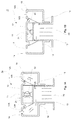
- FIG. 1A -1B is shown a schematical example of a nozzle according to an advantageous example of the invention as a cross section view.
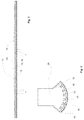
- figure 2 is shown a schematical example of a nozzle according to an advantageous example of the invention as a longitudinal view and
- figure 3 is shown a schematical example of an advantageous application of nozzles according to an advantageous example of the invention in an air turn device of a fiber web production line.
- figure 4 is shown another schematical example of a nozzle according to an advantageous example of the invention as a cross section view.
- figure 5 is shown schematically the example according to figure 4 in a perspective view.
- the nozzle 10 comprises a main frame part 11 that forms the outer part of the nozzle 10.
- the main frame part 11 comprises two side chambers 14, 15 on each longitudinal side of the nozzle 10.
- Each side chamber 14, 15 comprises a nozzle openings 16A, 16B, 17A, 17B for the air blow towards the fiber web (not shown) perpendicularly 16A, 17A and by inclined blows 16B, 17B.
- the main frame part 11 comprises between the side chamber 14, 15 an air channel 20 through which the air is lead to the side chambers 14, 15.
- the air channel 20 is formed U-shaped and its side walls have openings 19, 18 for leading the air into the side chambers 14, 15.
- a U-shaped inner part 13 is located inside the main frame part 11 a U-shaped inner part 13 is located inside the main frame part 11 a U-shaped inner part 13 is located inside the main frame part 11 a U-shaped inner part 13 is located.
- At least one adjustment means 12 is located for adjusting the location of the side walls of the inner part 13 to open or to close the openings 18, 19 of the main frame part 11 as shown in the figures 1A-1B .
- the openings 18, 19 are fully open so that air is passed from the air channel 20 to each of the side chambers 14, 15 and through each nozzle opening 16A, 16B, 17A, 17B as shown by arrows in the figure 1A .
- the distance between the upper surfaces of the main frame part 11 and the U-shaped inner part 13 has been adjusted such that the opening 19 on the left hand side in the figure is fully closed and the opening 18 on the right hand side in the figure is partially opened thus air is passed to the on the right hand side in the figure 1B located side chamber 15 and through the nozzle opening 16A, 16B as shown by the arrows in the figure 1B .
- the nozzle 10 may comprise as the nozzle opening/-s 16A, 16B, 17A, 17B a single or a double slot opening or advantageously there are several substantially circular nozzle openings 16A, 16B, 17A, 17B located spaced apart in at least one line extending substantially in longitudinal direction of the nozzle 10.
- the nozzle 10 is shown as a longitudinal view.
- the nozzle 10 comprises the main frame part 11 and its side chambers 14; 15, one of which can be seen in this longitudinal side view of the nozzle 10, and the inner part 13.
- the nozzle 10 is formed as a longitudinally extending beam like structure.
- curvature of the nozzle can be adjusted by the adjustment means 12.
- the distance between the upper surface of the U-shaped inner part 13 and the upper surface of the U-shaped part of the main frame part 11 is adjusted.
- the distance of the nozzle's 10 upper surface from the surface of the fiber web can be adjusted.
- FIG 3 is shown an air-turn device 25 of a fiber web production line constructed by the nozzles 10 according to the invention. As can be seen the nozzles 10 are located next to each other in curved positions, the curvature can further more accurately be adjusted by the adjustment means 12 of the nozzles 10.
- FIG. 4 - 5 is shown another advantageous example of the nozzle 10 comprising a main frame part 11 that forms the outer part of the nozzle 10.
- the main frame part 11 comprises two side chambers 14, 15 on each longitudinal side of the nozzle 10.
- Each side chamber 14, 15 comprise nozzle openings 17A, 16A for the air blow towards the fiber web (not shown) perpendicularly.
- the main frame part 11 comprises between the side chamber 14, 15 an air channel 20 through which the air is lead to the side chambers 14, 15.
- the air channel 20 is formed U-shaped and its side walls have openings 19, 18 for leading the air into the side chambers 14, 15.
- a U-shaped inner part 13 is located inside the main frame part 11 a U-shaped inner part 13 is located.
- At least one adjustment means 12 is located for adjusting the location of the side walls of the inner part 13 to open or to close the openings 18, 19 of the main frame part 11.
- the openings 18, 19 are fully open so that air is passed from the air channel 20 to each of the side chambers 14, 15 and through each nozzle opening 17A, 16A as shown by arrows in the figure 5 .
- the nozzle 10 comprises several substantially circular nozzle openings 16A, 17A located spaced apart in one line for each side chamber 14, 15 extending substantially in longitudinal direction of the nozzle 10.
- adjustment means 12 for adjusting the curvature of the nozzle 10 advantageously, as shown in figure 5 , there are several adjustment means 12 located apart in the longitudinal direction of the nozzle 10.
- the nozzle 10 is formed as a longitudinally extending beam like structure.
- the curvature of the nozzle 10 can be adjusted by the adjustment means 12.
- the distance between the upper surface of the U-shaped inner part 13 and the upper surface of the U-shaped part of the main frame part 11 is adjusted.
- the distance of the nozzle's 10 upper surface from the surface of the fiber web can be adjusted.
- the nozzle 10 is formed as welded construction comprising a U-shaped inner part 13 and a main frame part 11 between of which the adjustment mechanism 12, comprising a screw 21 and bushings 22, is attached by a welding at each end.
- the adjustment mechanism 12 comprising a screw 21 and bushings 22
- the inner U-shaped part 13 opens/closes the openings 18, 19 in the side walls of the main frame part 11, whereby the air blows can be regulated without changing the height of the nozzle 10.
- dividing plates (not shown) provided in order to divide the nozzle into sections in longitudinal direction of the nozzle, i.e. in cross-direction of the direction of travel of the fiber web.
- each section is advantageously provided with its adjustment mechanism and thus each section can be adjusted individually.
- the nozzle 10 may comprise cross-screws (not shown) with movement clearance attached between the walls of the inner U-shaped part 13 by which the bending of the nozzle 10 can be adjusted in travel direction of the fiber web.
Landscapes
- Engineering & Computer Science (AREA)
- Textile Engineering (AREA)
- Mechanical Engineering (AREA)
- General Engineering & Computer Science (AREA)
- Paper (AREA)
- Treatment Of Fiber Materials (AREA)
Priority Applications (5)
| Application Number | Priority Date | Filing Date | Title |
|---|---|---|---|
| EP16175902.2A EP3260802B1 (de) | 2016-06-23 | 2016-06-23 | Düse für eine vorrichtung zur berührungslosen behandlung einer laufenden faserstoffbahn |
| CA2967205A CA2967205A1 (en) | 2016-06-23 | 2017-05-12 | Nozzle of a device for contact-free treatment of a running fiber web |
| JP2017002759U JP3212246U (ja) | 2016-06-23 | 2017-06-20 | 走行する繊維ウェブの非接触処理のための装置のノズル |
| US15/630,932 US10006709B2 (en) | 2016-06-23 | 2017-06-22 | Nozzle of a device for contact—free treatment of a running fiber web |
| CN201720743790.1U CN207103078U (zh) | 2016-06-23 | 2017-06-23 | 用于运行的纤维幅材的无接触处理的装置的喷嘴 |
Applications Claiming Priority (1)
| Application Number | Priority Date | Filing Date | Title |
|---|---|---|---|
| EP16175902.2A EP3260802B1 (de) | 2016-06-23 | 2016-06-23 | Düse für eine vorrichtung zur berührungslosen behandlung einer laufenden faserstoffbahn |
Publications (2)
| Publication Number | Publication Date |
|---|---|
| EP3260802A1 true EP3260802A1 (de) | 2017-12-27 |
| EP3260802B1 EP3260802B1 (de) | 2019-10-09 |
Family
ID=56235658
Family Applications (1)
| Application Number | Title | Priority Date | Filing Date |
|---|---|---|---|
| EP16175902.2A Active EP3260802B1 (de) | 2016-06-23 | 2016-06-23 | Düse für eine vorrichtung zur berührungslosen behandlung einer laufenden faserstoffbahn |
Country Status (5)
| Country | Link |
|---|---|
| US (1) | US10006709B2 (de) |
| EP (1) | EP3260802B1 (de) |
| JP (1) | JP3212246U (de) |
| CN (1) | CN207103078U (de) |
| CA (1) | CA2967205A1 (de) |
Families Citing this family (2)
| Publication number | Priority date | Publication date | Assignee | Title |
|---|---|---|---|---|
| EP3260802B1 (de) * | 2016-06-23 | 2019-10-09 | Valmet Technologies Oy | Düse für eine vorrichtung zur berührungslosen behandlung einer laufenden faserstoffbahn |
| CN112499346A (zh) * | 2020-12-28 | 2021-03-16 | 滁州卷烟材料厂 | 一种气撑式烟用铝箔纸整平机构 |
Citations (6)
| Publication number | Priority date | Publication date | Assignee | Title |
|---|---|---|---|---|
| DE2934967A1 (de) * | 1978-08-29 | 1980-03-13 | Caratsch Hans Peter | Schwebeduesentrockner |
| EP0548419A1 (de) | 1990-06-02 | 1993-06-30 | Spooner Industries Limited | Pneumatische Umlenkvorrichtung |
| EP0726220B1 (de) | 1995-02-10 | 1999-04-07 | Valmet Corporation | Verfahren und Vorrichtung zum berührungslosen Behandeln einer Warenbahn |
| WO2001002643A1 (en) * | 1999-06-30 | 2001-01-11 | Metso Paper, Inc. | Nozzle arrangement in airborne web-drying and method for improving heat transfer in airborne web-drying |
| JP2002273272A (ja) * | 2001-03-16 | 2002-09-24 | Ishikawajima Harima Heavy Ind Co Ltd | エア吹出ノズル |
| DE202012005534U1 (de) | 2012-06-06 | 2012-07-17 | Metso Paper, Inc. | Variable Belüftungsdüse zur Behandlung einer Faserbahn |
Family Cites Families (22)
| Publication number | Priority date | Publication date | Assignee | Title |
|---|---|---|---|---|
| US3303576A (en) * | 1965-05-28 | 1967-02-14 | Procter & Gamble | Apparatus for drying porous paper |
| JPS5241370B2 (de) * | 1973-09-14 | 1977-10-18 | ||
| US4952128A (en) * | 1987-09-22 | 1990-08-28 | Chicopee | Transverse web forming apparatus |
| DE4110875A1 (de) | 1991-04-04 | 1992-10-08 | Voith Gmbh J M | Trockenpartie |
| FI105533B (fi) * | 1992-10-26 | 2000-09-15 | Valmet Paper Machinery Inc | Suihkupäällystyslaitteisto ja -menetelmä |
| FI94271C (fi) * | 1992-11-03 | 1995-08-10 | Valmet Paper Machinery Inc | Menetelmä telojen puhdistamiseksi ja telanpuhdistuslaite |
| FI94176C (fi) * | 1992-12-16 | 1995-07-25 | Valmet Paper Machinery Inc | Menetelmä ja laite liikkuvan radan reunan seurannassa |
| DE4401582A1 (de) * | 1994-01-20 | 1994-06-09 | Voith Gmbh J M | Verfahren und Vorrichtung zum Fördern eines Flüssigkeits-Gas-Gemisches von einem Zulauf zu einem Auslauf, insbesondere für die Papierindustrie |
| US5588223A (en) * | 1994-06-14 | 1996-12-31 | Asea Brown Boveri Inc. | Restrained paper dryer |
| FI112509B (fi) * | 1994-06-15 | 2003-12-15 | Metso Paper Inc | Paperikoneen kitaformeri |
| FR2732044B1 (fr) * | 1995-03-20 | 1997-04-30 | Kaysersberg Sa | Procede d'essorage d'une feuille de matiere cellulosique par air chaud traversant sous haut vide |
| FI98944C (fi) * | 1995-10-25 | 1997-09-10 | Valmet Corp | Menetelmä ja laite paperiradan tai vastaavan päällysteen kuivatuksessa |
| US6119362A (en) * | 1996-06-19 | 2000-09-19 | Valmet Corporation | Arrangements for impingement drying and/or through-drying of a paper or material web |
| FI107549B (fi) * | 1996-06-19 | 2001-08-31 | Metso Paper Inc | Menetelmä ja laite paperirainan tai vastaavan rainamaisen materiaalin päällepuhallus- ja/tai läpipuhalluskuivatuksen yhteydessä |
| FI101985B (fi) * | 1996-12-10 | 1998-09-30 | Valmet Corp | Menetelmä ja laitteisto kuiturainan kuivaamiseksi |
| FI971899A7 (fi) * | 1997-05-02 | 1998-11-03 | Sunds Defibrator Panelhandling | Menetelmä ja laitteisto levymäisen materiaalin käsittelemiseksi kaasum aisella aineella |
| US6360758B1 (en) * | 1999-09-10 | 2002-03-26 | Metso Paper, Inc. | Cleaning device in paper machines, board machines or other similar machines for cleaning a fabric, such as wire or felt |
| US6314659B1 (en) * | 1999-12-14 | 2001-11-13 | Valmet Inc. | Device and method for protecting a carrying fabric |
| US6485612B1 (en) * | 2001-05-18 | 2002-11-26 | Voith Paper, Inc. | Air press assembly for use in a paper-making machine |
| JP2010261120A (ja) * | 2009-05-02 | 2010-11-18 | Seed:Kk | 古紙再生装置の抄紙装置および古紙再生装置 |
| SE536662C2 (sv) * | 2012-11-13 | 2014-05-06 | Valmet Aktiebolag | Yankeecylinder gjord av stål |
| EP3260802B1 (de) * | 2016-06-23 | 2019-10-09 | Valmet Technologies Oy | Düse für eine vorrichtung zur berührungslosen behandlung einer laufenden faserstoffbahn |
-
2016
- 2016-06-23 EP EP16175902.2A patent/EP3260802B1/de active Active
-
2017
- 2017-05-12 CA CA2967205A patent/CA2967205A1/en not_active Abandoned
- 2017-06-20 JP JP2017002759U patent/JP3212246U/ja active Active
- 2017-06-22 US US15/630,932 patent/US10006709B2/en active Active
- 2017-06-23 CN CN201720743790.1U patent/CN207103078U/zh active Active
Patent Citations (7)
| Publication number | Priority date | Publication date | Assignee | Title |
|---|---|---|---|---|
| DE2934967A1 (de) * | 1978-08-29 | 1980-03-13 | Caratsch Hans Peter | Schwebeduesentrockner |
| EP0548419A1 (de) | 1990-06-02 | 1993-06-30 | Spooner Industries Limited | Pneumatische Umlenkvorrichtung |
| EP0726220B1 (de) | 1995-02-10 | 1999-04-07 | Valmet Corporation | Verfahren und Vorrichtung zum berührungslosen Behandeln einer Warenbahn |
| WO2001002643A1 (en) * | 1999-06-30 | 2001-01-11 | Metso Paper, Inc. | Nozzle arrangement in airborne web-drying and method for improving heat transfer in airborne web-drying |
| EP1218589A1 (de) | 1999-06-30 | 2002-07-03 | Metso Paper, Inc.(Reg.No. 763281) | Vorrichtung zum trocknen einer luftgetragenen bahn und verfahren zur verbesserung der wärmeübertragung in einer vorrichtung zum trocknen einer luftgetragenen bahn |
| JP2002273272A (ja) * | 2001-03-16 | 2002-09-24 | Ishikawajima Harima Heavy Ind Co Ltd | エア吹出ノズル |
| DE202012005534U1 (de) | 2012-06-06 | 2012-07-17 | Metso Paper, Inc. | Variable Belüftungsdüse zur Behandlung einer Faserbahn |
Also Published As
| Publication number | Publication date |
|---|---|
| JP3212246U (ja) | 2017-08-31 |
| CN207103078U (zh) | 2018-03-16 |
| US10006709B2 (en) | 2018-06-26 |
| EP3260802B1 (de) | 2019-10-09 |
| CA2967205A1 (en) | 2017-12-23 |
| US20170370644A1 (en) | 2017-12-28 |
Similar Documents
| Publication | Publication Date | Title |
|---|---|---|
| EP0743996B1 (de) | Papier-streichvorrichtung | |
| EP0507218B1 (de) | Trockenpartie | |
| DE69219707T2 (de) | Unterdruckdüsenanordnung zur Behandlung von Bahnen | |
| EP3260802B1 (de) | Düse für eine vorrichtung zur berührungslosen behandlung einer laufenden faserstoffbahn | |
| EP1903142B1 (de) | System zum Breitfahren einer Faserstoffbahn, Verfahren zur Steuerung der Randstreifenüberführung und Maschine zur Herstellung einer Faserstoffbahn | |
| EP0638159B1 (de) | Mehrzwecksblaskasten mit düsen | |
| JPH03887A (ja) | 抄紙機の乾燥部において使用するウエブの通紙を補強するための方法および装置 | |
| JPH10165873A (ja) | 特に紙またはボール紙からなる、移動する材料ウェブに液状またはペースト状塗布媒体を直接的または間接的に塗布するための装置 | |
| FI110627B (fi) | Menetelmä höyryn puhaltamiseksi paperirainaa vasten ja paperikoneen höyrylaatikko | |
| EP2792787B1 (de) | Verfahren and Vorrichtung zum Auftragen von Dampf | |
| EP2622137A1 (de) | Vorrichtung zum direkten oder indirekten auftrag von flüssigem bis pastösem auftragsmedium und verfahren zum betreiben einer derartigen vorrichtung | |
| JP2011508111A (ja) | 抄紙機若しくはその類の乾燥セクションにおける負圧制御装置及び方法 | |
| WO2004074148A2 (de) | Vorrichtung zum führen einer laufenden faserstoffbahn | |
| EP2868802A1 (de) | Anordnung einer Fasernetzherstellungslinie und Verfahren einer Fasernetzherstellungslinie | |
| DE69500781T2 (de) | Luftleitflügel für eine pneumatische Wendestange | |
| CA2169206C (en) | Method and device in contact-free treatment of a web | |
| EP2161373B1 (de) | Einrichtung zur Stabilisierung des Laufes einer Bahn in einer Papiermaschine und Verfahren zur Herstellung der Einrichtung | |
| GB1584770A (en) | Guide device for flexible webs | |
| DE102004003899A1 (de) | Vorrichtung zum Führen einer laufenden Faserstoffbahn | |
| EP2508672B1 (de) | Vorrichtung zum Überführen einer Bahn in einer Station einer Bahn-Herstellungs- oder Verarbeitungsmaschine | |
| EP4653614A1 (de) | Trocknungsgruppe und trocknungsabschnitt für eine faserbahnherstellungslinie | |
| EP1041026B1 (de) | Vorrichtung zum berührungslosen Umlenken einer bewegten Bahn | |
| EP4653613A1 (de) | Dichtungssystem für taschenraumenden | |
| DE10322521A1 (de) | Bahnführungs- und/oder Dichtungseinrichtung | |
| DE10142519A1 (de) | Ablöse- und Führungsvorrichtung |
Legal Events
| Date | Code | Title | Description |
|---|---|---|---|
| PUAI | Public reference made under article 153(3) epc to a published international application that has entered the european phase |
Free format text: ORIGINAL CODE: 0009012 |
|
| STAA | Information on the status of an ep patent application or granted ep patent |
Free format text: STATUS: THE APPLICATION HAS BEEN PUBLISHED |
|
| AK | Designated contracting states |
Kind code of ref document: A1 Designated state(s): AL AT BE BG CH CY CZ DE DK EE ES FI FR GB GR HR HU IE IS IT LI LT LU LV MC MK MT NL NO PL PT RO RS SE SI SK SM TR |
|
| AX | Request for extension of the european patent |
Extension state: BA ME |
|
| STAA | Information on the status of an ep patent application or granted ep patent |
Free format text: STATUS: REQUEST FOR EXAMINATION WAS MADE |
|
| 17P | Request for examination filed |
Effective date: 20180605 |
|
| RBV | Designated contracting states (corrected) |
Designated state(s): AL AT BE BG CH CY CZ DE DK EE ES FI FR GB GR HR HU IE IS IT LI LT LU LV MC MK MT NL NO PL PT RO RS SE SI SK SM TR |
|
| GRAP | Despatch of communication of intention to grant a patent |
Free format text: ORIGINAL CODE: EPIDOSNIGR1 |
|
| STAA | Information on the status of an ep patent application or granted ep patent |
Free format text: STATUS: GRANT OF PATENT IS INTENDED |
|
| INTG | Intention to grant announced |
Effective date: 20190528 |
|
| GRAS | Grant fee paid |
Free format text: ORIGINAL CODE: EPIDOSNIGR3 |
|
| GRAA | (expected) grant |
Free format text: ORIGINAL CODE: 0009210 |
|
| STAA | Information on the status of an ep patent application or granted ep patent |
Free format text: STATUS: THE PATENT HAS BEEN GRANTED |
|
| AK | Designated contracting states |
Kind code of ref document: B1 Designated state(s): AL AT BE BG CH CY CZ DE DK EE ES FI FR GB GR HR HU IE IS IT LI LT LU LV MC MK MT NL NO PL PT RO RS SE SI SK SM TR |
|
| REG | Reference to a national code |
Ref country code: GB Ref legal event code: FG4D |
|
| REG | Reference to a national code |
Ref country code: CH Ref legal event code: EP |
|
| REG | Reference to a national code |
Ref country code: IE Ref legal event code: FG4D |
|
| REG | Reference to a national code |
Ref country code: DE Ref legal event code: R096 Ref document number: 602016021973 Country of ref document: DE |
|
| REG | Reference to a national code |
Ref country code: AT Ref legal event code: REF Ref document number: 1189323 Country of ref document: AT Kind code of ref document: T Effective date: 20191115 |
|
| REG | Reference to a national code |
Ref country code: NL Ref legal event code: MP Effective date: 20191009 |
|
| REG | Reference to a national code |
Ref country code: LT Ref legal event code: MG4D |
|
| PG25 | Lapsed in a contracting state [announced via postgrant information from national office to epo] |
Ref country code: NO Free format text: LAPSE BECAUSE OF FAILURE TO SUBMIT A TRANSLATION OF THE DESCRIPTION OR TO PAY THE FEE WITHIN THE PRESCRIBED TIME-LIMIT Effective date: 20200109 Ref country code: PT Free format text: LAPSE BECAUSE OF FAILURE TO SUBMIT A TRANSLATION OF THE DESCRIPTION OR TO PAY THE FEE WITHIN THE PRESCRIBED TIME-LIMIT Effective date: 20200210 Ref country code: PL Free format text: LAPSE BECAUSE OF FAILURE TO SUBMIT A TRANSLATION OF THE DESCRIPTION OR TO PAY THE FEE WITHIN THE PRESCRIBED TIME-LIMIT Effective date: 20191009 Ref country code: LT Free format text: LAPSE BECAUSE OF FAILURE TO SUBMIT A TRANSLATION OF THE DESCRIPTION OR TO PAY THE FEE WITHIN THE PRESCRIBED TIME-LIMIT Effective date: 20191009 Ref country code: ES Free format text: LAPSE BECAUSE OF FAILURE TO SUBMIT A TRANSLATION OF THE DESCRIPTION OR TO PAY THE FEE WITHIN THE PRESCRIBED TIME-LIMIT Effective date: 20191009 Ref country code: SE Free format text: LAPSE BECAUSE OF FAILURE TO SUBMIT A TRANSLATION OF THE DESCRIPTION OR TO PAY THE FEE WITHIN THE PRESCRIBED TIME-LIMIT Effective date: 20191009 Ref country code: NL Free format text: LAPSE BECAUSE OF FAILURE TO SUBMIT A TRANSLATION OF THE DESCRIPTION OR TO PAY THE FEE WITHIN THE PRESCRIBED TIME-LIMIT Effective date: 20191009 Ref country code: LV Free format text: LAPSE BECAUSE OF FAILURE TO SUBMIT A TRANSLATION OF THE DESCRIPTION OR TO PAY THE FEE WITHIN THE PRESCRIBED TIME-LIMIT Effective date: 20191009 Ref country code: BG Free format text: LAPSE BECAUSE OF FAILURE TO SUBMIT A TRANSLATION OF THE DESCRIPTION OR TO PAY THE FEE WITHIN THE PRESCRIBED TIME-LIMIT Effective date: 20200109 Ref country code: GR Free format text: LAPSE BECAUSE OF FAILURE TO SUBMIT A TRANSLATION OF THE DESCRIPTION OR TO PAY THE FEE WITHIN THE PRESCRIBED TIME-LIMIT Effective date: 20200110 Ref country code: FI Free format text: LAPSE BECAUSE OF FAILURE TO SUBMIT A TRANSLATION OF THE DESCRIPTION OR TO PAY THE FEE WITHIN THE PRESCRIBED TIME-LIMIT Effective date: 20191009 |
|
| PG25 | Lapsed in a contracting state [announced via postgrant information from national office to epo] |
Ref country code: IS Free format text: LAPSE BECAUSE OF FAILURE TO SUBMIT A TRANSLATION OF THE DESCRIPTION OR TO PAY THE FEE WITHIN THE PRESCRIBED TIME-LIMIT Effective date: 20200224 Ref country code: RS Free format text: LAPSE BECAUSE OF FAILURE TO SUBMIT A TRANSLATION OF THE DESCRIPTION OR TO PAY THE FEE WITHIN THE PRESCRIBED TIME-LIMIT Effective date: 20191009 Ref country code: HR Free format text: LAPSE BECAUSE OF FAILURE TO SUBMIT A TRANSLATION OF THE DESCRIPTION OR TO PAY THE FEE WITHIN THE PRESCRIBED TIME-LIMIT Effective date: 20191009 |
|
| PG25 | Lapsed in a contracting state [announced via postgrant information from national office to epo] |
Ref country code: AL Free format text: LAPSE BECAUSE OF FAILURE TO SUBMIT A TRANSLATION OF THE DESCRIPTION OR TO PAY THE FEE WITHIN THE PRESCRIBED TIME-LIMIT Effective date: 20191009 |
|
| REG | Reference to a national code |
Ref country code: DE Ref legal event code: R097 Ref document number: 602016021973 Country of ref document: DE |
|
| PG2D | Information on lapse in contracting state deleted |
Ref country code: IS |
|
| PG25 | Lapsed in a contracting state [announced via postgrant information from national office to epo] |
Ref country code: DK Free format text: LAPSE BECAUSE OF FAILURE TO SUBMIT A TRANSLATION OF THE DESCRIPTION OR TO PAY THE FEE WITHIN THE PRESCRIBED TIME-LIMIT Effective date: 20191009 Ref country code: EE Free format text: LAPSE BECAUSE OF FAILURE TO SUBMIT A TRANSLATION OF THE DESCRIPTION OR TO PAY THE FEE WITHIN THE PRESCRIBED TIME-LIMIT Effective date: 20191009 Ref country code: RO Free format text: LAPSE BECAUSE OF FAILURE TO SUBMIT A TRANSLATION OF THE DESCRIPTION OR TO PAY THE FEE WITHIN THE PRESCRIBED TIME-LIMIT Effective date: 20191009 Ref country code: CZ Free format text: LAPSE BECAUSE OF FAILURE TO SUBMIT A TRANSLATION OF THE DESCRIPTION OR TO PAY THE FEE WITHIN THE PRESCRIBED TIME-LIMIT Effective date: 20191009 Ref country code: IS Free format text: LAPSE BECAUSE OF FAILURE TO SUBMIT A TRANSLATION OF THE DESCRIPTION OR TO PAY THE FEE WITHIN THE PRESCRIBED TIME-LIMIT Effective date: 20200209 |
|
| PLBE | No opposition filed within time limit |
Free format text: ORIGINAL CODE: 0009261 |
|
| STAA | Information on the status of an ep patent application or granted ep patent |
Free format text: STATUS: NO OPPOSITION FILED WITHIN TIME LIMIT |
|
| PG25 | Lapsed in a contracting state [announced via postgrant information from national office to epo] |
Ref country code: SM Free format text: LAPSE BECAUSE OF FAILURE TO SUBMIT A TRANSLATION OF THE DESCRIPTION OR TO PAY THE FEE WITHIN THE PRESCRIBED TIME-LIMIT Effective date: 20191009 Ref country code: IT Free format text: LAPSE BECAUSE OF FAILURE TO SUBMIT A TRANSLATION OF THE DESCRIPTION OR TO PAY THE FEE WITHIN THE PRESCRIBED TIME-LIMIT Effective date: 20191009 Ref country code: SK Free format text: LAPSE BECAUSE OF FAILURE TO SUBMIT A TRANSLATION OF THE DESCRIPTION OR TO PAY THE FEE WITHIN THE PRESCRIBED TIME-LIMIT Effective date: 20191009 |
|
| 26N | No opposition filed |
Effective date: 20200710 |
|
| PG25 | Lapsed in a contracting state [announced via postgrant information from national office to epo] |
Ref country code: SI Free format text: LAPSE BECAUSE OF FAILURE TO SUBMIT A TRANSLATION OF THE DESCRIPTION OR TO PAY THE FEE WITHIN THE PRESCRIBED TIME-LIMIT Effective date: 20191009 |
|
| PG25 | Lapsed in a contracting state [announced via postgrant information from national office to epo] |
Ref country code: MC Free format text: LAPSE BECAUSE OF FAILURE TO SUBMIT A TRANSLATION OF THE DESCRIPTION OR TO PAY THE FEE WITHIN THE PRESCRIBED TIME-LIMIT Effective date: 20191009 |
|
| REG | Reference to a national code |
Ref country code: CH Ref legal event code: PL |
|
| PG25 | Lapsed in a contracting state [announced via postgrant information from national office to epo] |
Ref country code: LU Free format text: LAPSE BECAUSE OF NON-PAYMENT OF DUE FEES Effective date: 20200623 |
|
| REG | Reference to a national code |
Ref country code: BE Ref legal event code: MM Effective date: 20200630 |
|
| PG25 | Lapsed in a contracting state [announced via postgrant information from national office to epo] |
Ref country code: CH Free format text: LAPSE BECAUSE OF NON-PAYMENT OF DUE FEES Effective date: 20200630 Ref country code: LI Free format text: LAPSE BECAUSE OF NON-PAYMENT OF DUE FEES Effective date: 20200630 Ref country code: IE Free format text: LAPSE BECAUSE OF NON-PAYMENT OF DUE FEES Effective date: 20200623 |
|
| PG25 | Lapsed in a contracting state [announced via postgrant information from national office to epo] |
Ref country code: BE Free format text: LAPSE BECAUSE OF NON-PAYMENT OF DUE FEES Effective date: 20200630 |
|
| REG | Reference to a national code |
Ref country code: AT Ref legal event code: UEP Ref document number: 1189323 Country of ref document: AT Kind code of ref document: T Effective date: 20191009 |
|
| PG25 | Lapsed in a contracting state [announced via postgrant information from national office to epo] |
Ref country code: TR Free format text: LAPSE BECAUSE OF FAILURE TO SUBMIT A TRANSLATION OF THE DESCRIPTION OR TO PAY THE FEE WITHIN THE PRESCRIBED TIME-LIMIT Effective date: 20191009 Ref country code: MT Free format text: LAPSE BECAUSE OF FAILURE TO SUBMIT A TRANSLATION OF THE DESCRIPTION OR TO PAY THE FEE WITHIN THE PRESCRIBED TIME-LIMIT Effective date: 20191009 Ref country code: CY Free format text: LAPSE BECAUSE OF FAILURE TO SUBMIT A TRANSLATION OF THE DESCRIPTION OR TO PAY THE FEE WITHIN THE PRESCRIBED TIME-LIMIT Effective date: 20191009 |
|
| PG25 | Lapsed in a contracting state [announced via postgrant information from national office to epo] |
Ref country code: MK Free format text: LAPSE BECAUSE OF FAILURE TO SUBMIT A TRANSLATION OF THE DESCRIPTION OR TO PAY THE FEE WITHIN THE PRESCRIBED TIME-LIMIT Effective date: 20191009 |
|
| PGFP | Annual fee paid to national office [announced via postgrant information from national office to epo] |
Ref country code: DE Payment date: 20250618 Year of fee payment: 10 |
|
| PGFP | Annual fee paid to national office [announced via postgrant information from national office to epo] |
Ref country code: GB Payment date: 20250618 Year of fee payment: 10 |
|
| PGFP | Annual fee paid to national office [announced via postgrant information from national office to epo] |
Ref country code: FR Payment date: 20250625 Year of fee payment: 10 |
|
| PGFP | Annual fee paid to national office [announced via postgrant information from national office to epo] |
Ref country code: AT Payment date: 20250620 Year of fee payment: 10 |