EP3260848B1 - Appareil d'inspection radiographique - Google Patents
Appareil d'inspection radiographique Download PDFInfo
- Publication number
- EP3260848B1 EP3260848B1 EP16752294.5A EP16752294A EP3260848B1 EP 3260848 B1 EP3260848 B1 EP 3260848B1 EP 16752294 A EP16752294 A EP 16752294A EP 3260848 B1 EP3260848 B1 EP 3260848B1
- Authority
- EP
- European Patent Office
- Prior art keywords
- inspection
- ray
- electric power
- malfunction
- unit
- Prior art date
- Legal status (The legal status is an assumption and is not a legal conclusion. Google has not performed a legal analysis and makes no representation as to the accuracy of the status listed.)
- Active
Links
Images


Classifications
-
- G—PHYSICS
- G01—MEASURING; TESTING
- G01N—INVESTIGATING OR ANALYSING MATERIALS BY DETERMINING THEIR CHEMICAL OR PHYSICAL PROPERTIES
- G01N23/00—Investigating or analysing materials by the use of wave or particle radiation, e.g. X-rays or neutrons, not covered by groups G01N3/00 – G01N17/00, G01N21/00 or G01N22/00
- G01N23/02—Investigating or analysing materials by the use of wave or particle radiation, e.g. X-rays or neutrons, not covered by groups G01N3/00 – G01N17/00, G01N21/00 or G01N22/00 by transmitting the radiation through the material
- G01N23/04—Investigating or analysing materials by the use of wave or particle radiation, e.g. X-rays or neutrons, not covered by groups G01N3/00 – G01N17/00, G01N21/00 or G01N22/00 by transmitting the radiation through the material and forming images of the material
-
- G—PHYSICS
- G01—MEASURING; TESTING
- G01N—INVESTIGATING OR ANALYSING MATERIALS BY DETERMINING THEIR CHEMICAL OR PHYSICAL PROPERTIES
- G01N23/00—Investigating or analysing materials by the use of wave or particle radiation, e.g. X-rays or neutrons, not covered by groups G01N3/00 – G01N17/00, G01N21/00 or G01N22/00
- G01N23/02—Investigating or analysing materials by the use of wave or particle radiation, e.g. X-rays or neutrons, not covered by groups G01N3/00 – G01N17/00, G01N21/00 or G01N22/00 by transmitting the radiation through the material
- G01N23/06—Investigating or analysing materials by the use of wave or particle radiation, e.g. X-rays or neutrons, not covered by groups G01N3/00 – G01N17/00, G01N21/00 or G01N22/00 by transmitting the radiation through the material and measuring the absorption
- G01N23/083—Investigating or analysing materials by the use of wave or particle radiation, e.g. X-rays or neutrons, not covered by groups G01N3/00 – G01N17/00, G01N21/00 or G01N22/00 by transmitting the radiation through the material and measuring the absorption the radiation being X-rays
-
- G—PHYSICS
- G01—MEASURING; TESTING
- G01N—INVESTIGATING OR ANALYSING MATERIALS BY DETERMINING THEIR CHEMICAL OR PHYSICAL PROPERTIES
- G01N23/00—Investigating or analysing materials by the use of wave or particle radiation, e.g. X-rays or neutrons, not covered by groups G01N3/00 – G01N17/00, G01N21/00 or G01N22/00
- G01N23/02—Investigating or analysing materials by the use of wave or particle radiation, e.g. X-rays or neutrons, not covered by groups G01N3/00 – G01N17/00, G01N21/00 or G01N22/00 by transmitting the radiation through the material
- G01N23/06—Investigating or analysing materials by the use of wave or particle radiation, e.g. X-rays or neutrons, not covered by groups G01N3/00 – G01N17/00, G01N21/00 or G01N22/00 by transmitting the radiation through the material and measuring the absorption
- G01N23/18—Investigating the presence of flaws defects or foreign matter
-
- G—PHYSICS
- G06—COMPUTING OR CALCULATING; COUNTING
- G06F—ELECTRIC DIGITAL DATA PROCESSING
- G06F1/00—Details not covered by groups G06F3/00 - G06F13/00 and G06F21/00
- G06F1/26—Power supply means, e.g. regulation thereof
- G06F1/263—Arrangements for using multiple switchable power supplies, e.g. battery and AC
-
- G—PHYSICS
- G06—COMPUTING OR CALCULATING; COUNTING
- G06F—ELECTRIC DIGITAL DATA PROCESSING
- G06F1/00—Details not covered by groups G06F3/00 - G06F13/00 and G06F21/00
- G06F1/26—Power supply means, e.g. regulation thereof
- G06F1/30—Means for acting in the event of power-supply failure or interruption, e.g. power-supply fluctuations
-
- H—ELECTRICITY
- H02—GENERATION; CONVERSION OR DISTRIBUTION OF ELECTRIC POWER
- H02J—ELECTRIC POWER NETWORKS; CIRCUIT ARRANGEMENTS OR SYSTEMS FOR SUPPLYING OR DISTRIBUTING ELECTRIC POWER; SYSTEMS FOR STORING ELECTRIC ENERGY
- H02J9/00—Circuit arrangements for emergency or stand-by power supply, e.g. for emergency lighting
- H02J9/04—Circuit arrangements for emergency or stand-by power supply, e.g. for emergency lighting in which the distribution system is disconnected from the normal source and connected to a standby source
- H02J9/06—Circuit arrangements for emergency or stand-by power supply, e.g. for emergency lighting in which the distribution system is disconnected from the normal source and connected to a standby source with automatic change-over, e.g. UPS systems
-
- H—ELECTRICITY
- H05—ELECTRIC TECHNIQUES NOT OTHERWISE PROVIDED FOR
- H05G—X-RAY TECHNIQUE
- H05G1/00—X-ray apparatus involving X-ray tubes; Circuits therefor
- H05G1/08—Electrical details
- H05G1/10—Power supply arrangements for feeding the X-ray tube
-
- A—HUMAN NECESSITIES
- A61—MEDICAL OR VETERINARY SCIENCE; HYGIENE
- A61B—DIAGNOSIS; SURGERY; IDENTIFICATION
- A61B2560/00—Constructional details of operational features of apparatus; Accessories for medical measuring apparatus
- A61B2560/02—Operational features
- A61B2560/0204—Operational features of power management
- A61B2560/0214—Operational features of power management of power generation or supply
-
- G—PHYSICS
- G01—MEASURING; TESTING
- G01N—INVESTIGATING OR ANALYSING MATERIALS BY DETERMINING THEIR CHEMICAL OR PHYSICAL PROPERTIES
- G01N2223/00—Investigating materials by wave or particle radiation
- G01N2223/30—Accessories, mechanical or electrical features
- G01N2223/304—Accessories, mechanical or electrical features electric circuits, signal processing
-
- G—PHYSICS
- G01—MEASURING; TESTING
- G01N—INVESTIGATING OR ANALYSING MATERIALS BY DETERMINING THEIR CHEMICAL OR PHYSICAL PROPERTIES
- G01N2223/00—Investigating materials by wave or particle radiation
- G01N2223/30—Accessories, mechanical or electrical features
- G01N2223/32—Accessories, mechanical or electrical features adjustments of elements during operation
-
- G—PHYSICS
- G01—MEASURING; TESTING
- G01N—INVESTIGATING OR ANALYSING MATERIALS BY DETERMINING THEIR CHEMICAL OR PHYSICAL PROPERTIES
- G01N2223/00—Investigating materials by wave or particle radiation
- G01N2223/60—Specific applications or type of materials
- G01N2223/643—Specific applications or type of materials object on conveyor
-
- H—ELECTRICITY
- H02—GENERATION; CONVERSION OR DISTRIBUTION OF ELECTRIC POWER
- H02J—ELECTRIC POWER NETWORKS; CIRCUIT ARRANGEMENTS OR SYSTEMS FOR SUPPLYING OR DISTRIBUTING ELECTRIC POWER; SYSTEMS FOR STORING ELECTRIC ENERGY
- H02J2105/00—Networks for supplying or distributing electric power characterised by their spatial reach or by the load
- H02J2105/40—Networks for supplying or distributing electric power characterised by their spatial reach or by the load characterised by the loads connecting to the networks or being supplied by the networks
- H02J2105/46—Medical devices, medical implants or life supporting devices
Definitions
- the present invention relates to an X-ray inspection apparatus.
- An X-ray inspection apparatus including an X-ray source that radiates X-rays to a product and an X-ray detection unit that detects X-rays that have penetrated the product is known (e.g., see Patent Document 1).
- Each of EP 2 169 430 A1 and JP 2005 118348 A discloses an X-ray inspection apparatus comprising: an X-ray source configured to radiate X-rays to a product; an X-ray detection unit configured to detect X-rays that have penetrated the product; a processing unit; and an uninterruptible power supply electrically connected to the processing unit and configured to supply electric power thereto during an electric power failure of an external power supply, wherein the uninterruptible power supply is not electrically connected to the X-ray source.
- Patent Document 1 Japanese Patent No. 4686080
- an external power supply is normally used as an electric power supply.
- an operation of the X-ray inspection apparatus may be affected.
- an uninterruptible power supply may connect to the X-ray inspection apparatus.
- the electric power required by the X-ray inspection apparatus increases, there is a problem in that a size of the uninterruptible power supply increases because the electric power to be supplied from the uninterruptible power supply to the X-ray inspection apparatus increases during an electric power failure.
- an objective of the present invention is to provide an X-ray inspection apparatus capable of suppressing an increase in a size of an uninterruptible power supply.
- An X-ray inspection apparatus as a reference example includes: an X-ray source configured to radiate X-rays to a product; an X-ray detection unit configured to detect X-rays that have penetrated the product; and an uninterruptible power supply configured to supply electric power during an electric power failure of an external power supply, wherein the UPS is not electrically connected to the X-ray source.
- the uninterruptible power supply is not electrically connected to the X-ray source. Thereby, electric power is not supplied from the uninterruptible power supply to the X-ray source even during an electric power failure. Therefore, it is possible to suppress an increase in a size of the uninterruptible power supply because it is possible to suppress electric power to be supplied by the uninterruptible power supply during the electric power failure.
- the X-ray inspection apparatus further includes a processing unit configured to perform an inspection of the product based on an electric signal output from the X-ray detection unit and record inspection information regarding the inspection, wherein the uninterruptible power supply is electrically connected to the processing unit.
- a processing unit configured to perform an inspection of the product based on an electric signal output from the X-ray detection unit and record inspection information regarding the inspection, wherein the uninterruptible power supply is electrically connected to the processing unit.
- electric power is supplied from the uninterruptible power supply to the processing unit which records the inspection information regarding the inspection of the product, during an electric power failure. Therefore, it is possible to prevent the inspection information from being lost even when an electric power failure occurs.
- the X-ray inspection apparatus is configured to record first information relating to the inspection, from among the inspection information in a first storage area that is a temporary storage area
- the processing unit is configured to record second information regarding a result of the inspection, from among the inspection information in a second storage area that is a permanent storage area.
- it is possible to reliably record the second information by recording the second information regarding the result of the inspection onto the second storage area (for example, an HDD).
- the processing unit may be configured to associate a type of a malfunction with operation states of the X-ray source and the X-ray detection unit in recording the type of the malfunction and the operation states when the malfunction occurs in cases where the malfunction occurs in the X-ray source or the X-ray detection unit, the malfunction occurs in the uninterruptible power supply, and the electric power failure occurs as the malfunction of the external power supply.
- the processing unit may be configured to associate a type of a malfunction with operation states of the X-ray source and the X-ray detection unit in recording the type of the malfunction and the operation states when the malfunction occurs in cases where the malfunction occurs in the X-ray source or the X-ray detection unit, the malfunction occurs in the uninterruptible power supply, and the electric power failure occurs as the malfunction of the external power supply.
- it is possible to appropriately cope with the malfunction in accordance with the type of the malfunction occurred because the type of the malfunction and the operation state of the X-ray source or the X-ray detection unit are associated with each other in recording the type of the malfunction
- an X-ray inspection apparatus capable of suppressing an increase in a size of an uninterruptible power supply.
- an X-ray inspection apparatus 1 radiates X-rays to a product while conveying the product and detects X-rays in order to inspect whether or not a foreign object is mixed into the product.
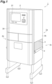
- the X-ray inspection apparatus 1 includes a main body 2, an X-ray shielding curtain 3, and a carrying conveyor 4. The X-ray inspection apparatus 1 inspects whether or not a foreign object is mixed into the product A or the like while the product A is conveyed in a conveying direction a.
- the main body 2 includes an inspection chamber 2a formed in a box shape.
- a carry-in port 2c through which the product A passes is provided in an upstream side wall 2b in the conveying direction a.
- a carry-out port 2e through which the product A passes is provided in a downstream side wall 2d in the conveying direction a.
- the X-ray shielding curtain 3 is provided at each of the carry-in port 2c and the carry-out port 2e. The X-ray shielding curtain 3 prevents scattered X-rays from leaking outside the inspection chamber 2a.
- a general flat belt conveyor is used for the carrying conveyor 4. Both ends of the carrying conveyor 4 protrude from the carry-in port 2c and the carry-out port 2e of the inspection chamber 2a, respectively.
- the carrying conveyor 4 receives the product A before an inspection from a carry-in conveyor (not illustrated) on an upstream side in the conveying direction a.
- the carrying conveyor 4 carries the product A inside the inspection chamber 2a from the carry-in port 2c.
- the carrying conveyor 4 carries the product A outside the inspection chamber 2a from the carry-out port 2e.
- the carrying conveyor 4 transfers the inspected product A to a carry-out conveyor (not illustrated) on a downstream side in the conveying direction a.
- a sorting function for the product A may be provided in the carry-out conveyor.
- the X-ray inspection apparatus 1 includes an inspection unit 10, a processing unit 20, an uninterruptible power supply (UPS) 30, and a main power switch S.
- an electrical connection relationship between components related to the supply of electric power indicated by a solid-line arrow in FIG. 3 is referred to as “electrically connected” and an electrical connection relationship between components other than the supply of electric power indicated by a broken line in FIG. 3 is referred to as “electrically connected as by an electric signal.”
- the inspection unit 10 includes an X-ray source 11, a communication unit 12, and an X-ray detection unit 13. As illustrated in FIGS. 2 and 3 , the X-ray source 11 is arranged above the inspection chamber 2a in the main body 2. The X-ray source 11 radiates X-rays to the product A carried in the inspection chamber 2a while forming an X-ray radiation area via a slit mechanism (not illustrated) or the like. The X-ray source 11 is electrically connected as by an electric signal to the communication unit 12. If a malfunction occurs in the X-ray source 11, the X-ray source 11 transmits information to the communication unit 12 indicating that a malfunction has occurred. The X-ray source 11 transmits information regarding an operation state of the X-ray source 11 to the communication unit 12.
- the communication unit 12 is an I/O board that intensively performs communication related to an input and output of information between the inspection unit 10 and the processing unit 20.
- the communication unit 12 is electrically connected as by an electric signal to a control unit 22 to be described below.
- the communication unit 12 communicates with the control unit 22 at a certain period (for example, every 100 ms). If a malfunction of the X-ray source 11 or a malfunction of the X-ray detection unit 13 occurs, the communication unit 12 transmits information to the control unit 22 indicating that a malfunction has occurred.
- the communication unit 12 transmits information regarding operation states transmitted from the X-ray source 11 and the X-ray detection unit 13 to the control unit 22.
- the X-ray detection unit 13 is arranged below the inspection chamber 2a in the main body 2 so that the X-ray detection unit 13 faces the X-ray source 11.
- the X-ray detection unit 13 includes a line sensor 14.
- the line sensor 14 includes a plurality of pixels arranged in a row in a width direction in the conveying direction a (a direction perpendicular to the conveying direction a and a vertical direction).
- the X-ray detection unit 13 detects X-rays that have penetrated the product A.
- the X-ray detection unit 13 is electrically connected as by an electric signal to the processing unit 20 (a control unit 22).
- the processing unit 20 a control unit 22
- the X-ray detection unit 13 acquires a detection signal at a predetermined timing.
- the X-ray detection unit 13 outputs the electric signal to the control unit 22 related to the detection signal. That is, the inspection unit 10 outputs an electric signal for inspecting the product A to the control unit 22.
- the X-ray detection unit 13 is electrically connected as by an electric signal to the communication unit 12. If a malfunction occurs in the X-ray detection unit 13, the X-ray detection unit 13 transmits information to the communication unit 12 indicating that a malfunction has occurred. The X-ray detection unit 13 transmits information regarding the operation state of the X-ray detection unit 13 to the communication unit 12.
- the UPS 15 has a battery 16 and is a device that supplies electric power of the battery 16 during an electric power failure in the external power supply E.
- the UPS 15 is electrically connected as by an electric signal to the control unit 22 to be described below.
- the UPS 15 communicates with the control unit 22 at a certain period (for example, every 10 s).
- the UPS 15 transmits information regarding the state of the UPS 15 to the control unit 22 at a certain period or in response to an inquiry from the control unit 22.
- the state of the UPS 15 includes a voltage of the external power supply E, the presence or the absence of an electric power failure in the external power supply E, and the remaining amount of the battery 16.
- the processing unit 20 inspects the product A based on the electric signal received from the X-ray detection unit 13, and records inspection information regarding the inspection.
- the processing unit 20 includes a monitor 21, the control unit 22, a random access memory (RAM) (a first storage area) 23, and a hard disk drive (HDD) (a second storage area) 24.
- RAM random access memory
- HDD hard disk drive
- the monitor 21 is provided in an upper part of a front face portion of the main body 2 (see FIG. 1 ).
- the monitor 21 is a display unit that displays an operation state of the X-ray inspection apparatus 1, an X-ray image of the product A, an inspection result, and the like.
- the monitor 21 has a touch panel function and performs display for an input operation.
- the input operation includes an input operation of a reservation setting, a start and a stop operation of the inspection unit 10, and other inspection management operations (a password setting and the like).
- the reservation setting is a setting related to the operation state of the inspection unit 10 to be set before or during the inspection.
- the monitor 21 is electrically connected as by an electric signal to the control unit 22, and transmits operation information related to the input operation to the control unit 22.
- the operation state of the inspection unit 10 includes operation states of the X-ray source 11 and the X-ray detection unit 13.
- the operation state of the X-ray source 11 is, for example, the intensity of X-rays output by the X-ray source 11.
- the intensity of the X-rays may be acquired based on, for example, a voltage and a current in the X-ray source 11.
- the operation state of the X-ray detection unit 13 is, for example, the detecting intensity of X-rays detected by the X-ray detection unit 13.
- the detected intensity of the X-rays may be acquired based on, for example, an output of the line sensor 14.
- the operation state of the inspection unit 10 includes an operating state of the inspection unit 10.
- the operating state of the inspection unit 10 includes, for example, a type and properties of the product A (a length along the conveying direction a or the like), a conveying speed of the carrying conveyor 4, set values of the voltage and current in the X-ray source 11, a sensitivity of the line sensor 14, inspection standards, and the like.
- the control unit 22 comprehensively controls processing related to the inspection in the processing unit 20.
- the control unit 22 performs image processing on an electric signal related to the X-ray image of the product A output from the X-ray detection unit 13, thereby inspecting the mixing of a foreign object or the like for the product A.
- the control unit 22 includes the RAM 23 and includes a central processing unit (CPU) and a read only memory (ROM).
- the control unit 22 records the inspection information regarding the inspection of the product A.
- the control unit 22 records (runs) first information relating to the inspection, from the inspection information onto the RAM 23.
- the RAM 23 is a temporary storage area.
- the control unit 22 can edit the first information recorded on the RAM 23 accordingly. For example, the control unit 22 can perform editing of adding new first information to the first information already stored in the first storage area.
- the first information includes the operation state of the inspection unit 10. Also, the first information includes operation history information (an operation record), NG history information, aggregated data, and information regarding a user, a use date and time, or the like of the X-ray inspection apparatus 1.
- the operation history information is created by the control unit 22 based on the operation information received from the monitor 21.
- the operation history information may be a time-series list created by performing editing of adding operation details every time that an operation such as an inspection start, an inspection stop, a setting change, or the like is performed.
- the NG history information is a time-series list created by performing editing of adding details of each product A having a problem in the inspection result, such as a product having a foreign object or a product having a missing article.
- the aggregated data is a list for each of a certain period of times created by performing classification by the presence or absence of a foreign object, a missing article, or the like, aggregating the number of products A, and performing editing of adding details.
- the control unit 22 records the second information regarding the result of the inspection, from the inspection information on the HDD 24.
- the HDD 24 is a permanent storage area.
- the control unit 22 records the second information on the HDD 24 for each inspection of each product A (in real time).
- the second information includes X-ray image data and inspection result data that are results of inspection of the product A.
- the inspection result data is details of the inspection result corresponding to the X-ray image data of each product A.
- the inspection result data includes, for example, a determination result of the inspection (the presence or absence of a foreign object, a missing article, or the like), an inspection date and time, and the like.
- the control unit 22 records the first information recorded on the RAM 23 onto the HDD 24, if the operation of the X-ray inspection apparatus 1 is stopped. Also, the control unit 22 records the first information recorded on the RAM 23 onto the HDD 24, if the risk of the X-ray inspection apparatus 1 stopping due to a malfunction occurring. The control unit 22 records (runs) the first information recorded on the HDD 24 onto the RAM 23, if the operation is activated (resumed) after the operation of the X-ray inspection apparatus 1 was stopped.
- the occurrence of a malfunction includes an occurrence of a malfunction of the inspection unit 10 (that is, a malfunction of the X-ray source 11 or the X-ray detection unit 13), an occurrence of a malfunction of the UPS 15, an occurrence of an electric power failure as a malfunction of the external power supply E, and the like.
- the control unit 22 receives information indicating that a malfunction has occurred in the X-ray source 11 or the X-ray detection unit 13 from the communication unit 12 in communication with the communication unit 12 at a certain periods.
- the control unit 22 transmits information indicating that a malfunction has occurred in the UPS 15 and information indicating that an electric power failure has occurred as a malfunction of the external power supply E from the UPS 15 in accordance with communication with the UPS 15 at a certain periods or with communication in response to an inquiry from the control unit 22.
- the control unit 22 associates and records the type of malfunction and the operation state of the inspection unit 10 (the X-ray source 11 and the X-ray detection unit 13) when the malfunction occurs. Specifically, the control unit 22 generates, for example, a single file named after a time at which the malfunction occurred. The control unit 22 associates the type of the malfunction with the information regarding the operation state of the inspection unit 10 when the malfunction occurs by indicating these together in this file. The control unit 22 records this file on the HDD 24.
- the control unit 22 runs the information related to the operation state of the inspection unit 10 onto the RAM 23.
- the control unit 22 utilizes the information regarding the operation state of the inspection unit 10 run onto the RAM 23 when the malfunction occurs as the information related to the operation state of the inspection unit 10 when the malfunction occurs. Consequently, the control unit 22 can associate the type of the malfunction with the operation state of the inspection unit 10 when the malfunction occurs. This information is valuable information for identifying a cause of occurrence of the malfunction.
- the malfunction of the inspection unit 10 includes a malfunction of the X-ray source 11, a malfunction of the communication unit 12, and a malfunction of the X-ray detection unit 13.
- the malfunction of the X-ray source 11 is, for example, a decrease in the intensity of X-rays output from the X-ray source 11.
- the malfunction of the communication unit 12 is, for example, inability to communicate related to an input and output of information between the inspection unit 10 and the control unit 22.
- the malfunction of the X-ray detection unit 13 is, for example, a decrease in the detecting intensity of X-rays detected by the X-ray detection unit 13.
- the malfunction of the UPS 15 is, for example, deterioration of the battery 16 or inability of the battery 16 to charge of the battery 16.
- An electric power failure as a malfunction of the external power supply E includes an electric power failure that the supply of electric power from the external power supply E is continuously interrupted (hereinafter simply referred to as a "electric power failure") and an instantaneous electric power failure that the supply of electric power from the external power supply E is instantaneously interrupted.
- examples of the operation state of the inspection unit 10 when a malfunction occurs include: a level of an intensity of X-rays output by the X-ray source 11 (a voltage and a current in the X-ray source 11); a level of a detection intensity of X-rays detected by the X-ray detection unit 13; a type of product A to be inspected by the X-ray inspection apparatus 1; a level of a conveying speed of the carrying conveyor 4; and a type of inspection standard, and the like when the malfunction occurs.
- a main power switch S is a principal electric power switch in the X-ray inspection apparatus 1.
- the main power switch S is electrically connected to the external power supply E. If the main power switch S is closed, the main power switch S passes a current from the external power supply E. If the main power switch S is open, the main power switch S shuts off the current from the external power supply E. In the following description, it is assumed that the main power switch S is closed.
- the inspection unit 10 is not electrically connected to the UPS 15 and is electrically connected to the external power supply E via the main power switch S. That is, the UPS 15 is not connected to supply electric power to the inspection unit 10. Neither electric power from the external power supply E nor electric power from the UPS 15 is supplied to the inspection unit 10 if an electric power failure of the external power supply E occurs. Therefore, electric power is not supplied from the UPS 15 to the X-ray source 11 during an electric power failure of the external power supply E.
- the processing unit 20 is electrically connected to the external power supply E via the UPS 15. That is, the UPS 15 is connected to supply electric power to the processing unit 20.
- the electric power from the battery 16 of the UPS 15 is supplied to the processing unit 20 if an electric power failure of the external power supply E occurs. Therefore, electric power is supplied from the UPS 15 to the processing unit 20 during an electric power failure, which records the inspection information regarding the inspection of the product A.
- the X-ray inspection apparatus 1 includes the X-ray source 11 that radiates X-rays to the product A, the X-ray detection unit 13 that detects X-rays that have penetrated the product A, and the UPS 15 that supplies electric power during an electric power failure.
- the UPS 15 is not electrically connected to the X-ray source 11. That is, No electrical connections capable of supplying electric power exist between the X-ray source 11 and the UPS 15. Thus, no electric power is supplied from the UPS 15 to the X-ray source 11 even during an electric power failure. Therefore, an increase in the size of the UPS 15 can be suppressed, because it is possible to suppress the electric power the UPS 15 supplies to the X-ray inspection apparatus 1 during the electric power failure.
- the electric power required by the X-ray source 11 is large, the electric power to be supplied to the X-ray inspection apparatus 1 by the UPS 15 during the electric power failure can be greatly suppressed, so that it is possible to effectively suppress the increase in the size of the UPS 15.
- the safety of a worker who works in the inspection unit 10 may decrease during the electric power failure, because, for example, an illumination in an installation place of the X-ray inspection apparatus 1 goes off. In this regard, in the X-ray inspection apparatus 1, the safety of the worker can be ensured, because the inspection unit 10 is not electrically connected to the UPS 15.
- the X-ray inspection apparatus 1 further includes the processing unit 20 that inspects the product A based on an electric signal output from the X-ray detection unit 13 and records inspection information regarding the inspection.
- the UPS 15 is electrically connected to the processing unit 20. That is, an electrical connection capable of supplying electric power exists between the processing unit 20 and the UPS 15. Thus, electric power is supplied from the UPS 15 to the processing unit 20 during an electric power failure, which records the inspection information regarding the inspection of the product A. Therefore, even if an electric power failure occurs, it is possible to prevent the inspection information from being lost.
- the processing unit 20 records first information relating to the inspection, from the inspection information onto the RAM 23 that is the temporary storage area.
- the processing unit 20 records second information regarding the result of the inspection, from the inspection information on the HDD 24 that is the permanent storage area.
- the first information relating to the inspection onto the RAM 23 for example, it is easy to add new first information to the first information already stored in the RAM 23. It is possible to reliably record the second information by recording the second information regarding the result of the inspection in the HDD 24.
- Both the first information (an operation record) relating to the inspection, from the inspection information, and the second information regarding the result of the inspection are permanently recorded and thus protected, because the first information stored in the RAM 23 during the operation of the X-ray inspection apparatus 1 is saved onto the HDD 24 when the operation of the X-ray inspection apparatus 1 is stopped.
- the processing unit 20 associates a type of malfunction with operation states of the X-ray source 11 and the X-ray detection unit 13 in recording the type of malfunction and the operation states when the malfunction occurs in cases where the malfunction occurs in the X-ray source 11 or the X-ray detection unit 13, the malfunction occurs in the UPS 15, and the electric power failure occurs as the malfunction of the external power supply E.
- the processing unit 20 associates a type of malfunction with operation states of the X-ray source 11 and the X-ray detection unit 13 in recording the type of malfunction and the operation states when the malfunction occurs in cases where the malfunction occurs in the X-ray source 11 or the X-ray detection unit 13, the malfunction occurs in the UPS 15, and the electric power failure occurs as the malfunction of the external power supply E.
- the type of malfunction and the operation state of the X-ray source 11 or the X-ray detection unit 13 when the malfunction occurs are associated with each other in recording the type of the malfunction and the operation state when the malfunction occurs in a case where the malfunction occurs.
- the X-ray inspection apparatus 1 has been described as an example of an inspection apparatus including the inspection unit 10 and the processing unit 20 in the above-described embodiment. However, it is also possible to make a configuration in which the UPS 15 is not electrically connected to the inspection unit 10 and make a configuration in which the UPS 15 is electrically connected to the processing unit 20 even in another inspection apparatus such as, for example, a metal detector, a near infrared ray inspection apparatus, a weight checker (a weight inspection apparatus), or a seal checker.
Landscapes
- Health & Medical Sciences (AREA)
- General Physics & Mathematics (AREA)
- Physics & Mathematics (AREA)
- Engineering & Computer Science (AREA)
- Immunology (AREA)
- Biochemistry (AREA)
- General Health & Medical Sciences (AREA)
- Analytical Chemistry (AREA)
- Chemical & Material Sciences (AREA)
- Pathology (AREA)
- Life Sciences & Earth Sciences (AREA)
- Power Engineering (AREA)
- Theoretical Computer Science (AREA)
- Business, Economics & Management (AREA)
- Emergency Management (AREA)
- Toxicology (AREA)
- General Engineering & Computer Science (AREA)
- Analysing Materials By The Use Of Radiation (AREA)
Claims (2)
- Dispositif d'inspection radiographique (1), comprenant :une source de rayons X (11) prévue pour émettre des rayons X vers un produit ;une unité de détection de rayons X (13) prévue pour détecter les rayons X traversant le produit ;une unité de traitement (20) ; etune alimentation électrique sans coupure (15) reliée électriquement à l'unité de traitement et prévue pour alimenter celle-ci en énergie électrique en cas de panne d'une alimentation électrique externe,
oùl'alimentation électrique sans coupure n'est pas reliée électriquement à la source de rayons X,caractérisé en ce quel'unité de traitement est prévue poureffectuer une inspection du produit sur la base d'un signal électrique émis par l'unité de détection de rayons X,enregistrer des premières informations concernant l'inspection, parmi les informations relatives à l'inspection, dans une première zone de mémorisation (23) étant une zone de mémorisation temporaire, enregistrer des deuxièmes informations concernant un résultat de l'inspection, parmi les informations d'inspection, dans une deuxième zone de mémorisation (24) étant une zone de mémorisation permanente, et enregistrer les premières informations enregistrées dans la première zone de mémorisation dans la deuxième zone de mémorisation, en cas de panne de l'alimentation électrique externe. - Dispositif d'inspection radiographique (1) selon la revendication 1, où l'unité de traitement (20) est prévue pour enregistrer les premières informations enregistrées de la deuxième zone de mémorisation (24) dans la première zone de mémorisation (23), si le fonctionnement du dispositif d'inspection radiographique est repris après interruption.
Applications Claiming Priority (2)
| Application Number | Priority Date | Filing Date | Title |
|---|---|---|---|
| JP2015032301A JP6530926B2 (ja) | 2015-02-20 | 2015-02-20 | X線検査装置 |
| PCT/JP2016/053239 WO2016132907A1 (fr) | 2015-02-20 | 2016-02-03 | Dispositif d'inspection radiographique |
Publications (3)
| Publication Number | Publication Date |
|---|---|
| EP3260848A1 EP3260848A1 (fr) | 2017-12-27 |
| EP3260848A4 EP3260848A4 (fr) | 2018-10-24 |
| EP3260848B1 true EP3260848B1 (fr) | 2024-07-10 |
Family
ID=56692029
Family Applications (1)
| Application Number | Title | Priority Date | Filing Date |
|---|---|---|---|
| EP16752294.5A Active EP3260848B1 (fr) | 2015-02-20 | 2016-02-03 | Appareil d'inspection radiographique |
Country Status (6)
| Country | Link |
|---|---|
| US (1) | US10859514B2 (fr) |
| EP (1) | EP3260848B1 (fr) |
| JP (1) | JP6530926B2 (fr) |
| KR (1) | KR101953581B1 (fr) |
| CN (1) | CN107250776A (fr) |
| WO (1) | WO2016132907A1 (fr) |
Families Citing this family (1)
| Publication number | Priority date | Publication date | Assignee | Title |
|---|---|---|---|---|
| EP4585161A1 (fr) * | 2024-01-12 | 2025-07-16 | Koninklijke Philips N.V. | Localisation de perturbations d'alimentation électrique |
Family Cites Families (18)
| Publication number | Priority date | Publication date | Assignee | Title |
|---|---|---|---|---|
| US4797907A (en) * | 1987-08-07 | 1989-01-10 | Diasonics Inc. | Battery enhanced power generation for mobile X-ray machine |
| CN2167366Y (zh) | 1993-05-26 | 1994-06-01 | 能源部电力建设研究所 | 裂缝检测仪 |
| JP3349555B2 (ja) | 1993-06-24 | 2002-11-25 | フマキラー株式会社 | 発熱発泡型消臭剤組成物 |
| JP3449555B2 (ja) * | 2000-11-01 | 2003-09-22 | 理学電機工業株式会社 | 分析装置 |
| JP2002372505A (ja) * | 2001-06-13 | 2002-12-26 | Rigaku Industrial Co | 瞬間停電保護機能付き試料分析装置 |
| JP4686080B2 (ja) * | 2001-09-11 | 2011-05-18 | 株式会社イシダ | X線検査装置 |
| JP2004020297A (ja) * | 2002-06-14 | 2004-01-22 | Chubu Medical:Kk | X線異物検査装置 |
| PT1516299E (pt) * | 2002-06-24 | 2007-02-28 | Angeleyel Inc | Alarme |
| US7514703B2 (en) * | 2003-06-10 | 2009-04-07 | Fujifilm Corporation | Image information detecting cassette |
| JP4773049B2 (ja) | 2003-10-17 | 2011-09-14 | 株式会社島津製作所 | 放射線撮像装置 |
| US7916834B2 (en) | 2007-02-12 | 2011-03-29 | Thermo Niton Analyzers Llc | Small spot X-ray fluorescence (XRF) analyzer |
| JP2009005451A (ja) * | 2007-06-20 | 2009-01-08 | Tdk Lambda Corp | バックアップ給電システム |
| WO2009011027A1 (fr) * | 2007-07-17 | 2009-01-22 | Shimadzu Corporation | Dispositif de source de puissance pour détecteur, système de détection de lumière ou de rayonnement ayant le dispositif |
| WO2009101772A1 (fr) * | 2008-02-12 | 2009-08-20 | Ishida Co., Ltd. | Appareil d'inspection aux rayons x |
| US7852985B2 (en) * | 2009-03-13 | 2010-12-14 | General Electric Company | Digital image detector with removable battery |
| GB2498103B (en) | 2010-10-26 | 2016-03-30 | Hewlett Packard Development Co | Backup power supply systems and methods |
| CN103220977B (zh) * | 2010-11-18 | 2015-06-17 | 株式会社日立医疗器械 | 移动型x射线装置 |
| WO2013140512A1 (fr) * | 2012-03-19 | 2013-09-26 | 富士通株式会社 | Dispositif de traitement d'informations, procédé de détection d'erreur de connexion et programme de détection d'erreur de connexion |
-
2015
- 2015-02-20 JP JP2015032301A patent/JP6530926B2/ja active Active
-
2016
- 2016-02-03 KR KR1020177022886A patent/KR101953581B1/ko active Active
- 2016-02-03 EP EP16752294.5A patent/EP3260848B1/fr active Active
- 2016-02-03 CN CN201680010347.1A patent/CN107250776A/zh active Pending
- 2016-02-03 US US15/551,382 patent/US10859514B2/en active Active
- 2016-02-03 WO PCT/JP2016/053239 patent/WO2016132907A1/fr not_active Ceased
Also Published As
| Publication number | Publication date |
|---|---|
| KR20170102559A (ko) | 2017-09-11 |
| US20180027640A1 (en) | 2018-01-25 |
| EP3260848A1 (fr) | 2017-12-27 |
| JP6530926B2 (ja) | 2019-06-12 |
| CN107250776A (zh) | 2017-10-13 |
| EP3260848A4 (fr) | 2018-10-24 |
| KR101953581B1 (ko) | 2019-03-04 |
| JP2016153770A (ja) | 2016-08-25 |
| WO2016132907A1 (fr) | 2016-08-25 |
| US10859514B2 (en) | 2020-12-08 |
Similar Documents
| Publication | Publication Date | Title |
|---|---|---|
| KR101762185B1 (ko) | 다수의 시설들에서의 방사선의 중앙 검출 | |
| US8019040B2 (en) | X-ray inspection device and production system | |
| EP3260848B1 (fr) | Appareil d'inspection radiographique | |
| EP4053598A1 (fr) | Dispositif de notification d'état, procédé de commande de dispositif de notification d'état, programme de traitement d'informations et support d'enregistrement | |
| JP2004226253A (ja) | X線異物検査装置 | |
| JP6510264B2 (ja) | 物品検査装置 | |
| CN112240223B (zh) | 井下异常信号的识别方法、装置、电子设备及存储介质 | |
| CN210571032U (zh) | 一种用于受限空间的热灾害检测装置 | |
| KR101094158B1 (ko) | 전신오염감시기 기체 흐름 비례계수기형 방사선검출기 이상검사회로 및 방법 | |
| JP2009202237A (ja) | 金属帯のトリミング異常検出方法および装置 | |
| KR200486224Y1 (ko) | 컨베이어 벨트 풀리의 손상 감지 시스템 | |
| US20200184619A1 (en) | Article inspection information management apparatus, program for the same, and article inspection system | |
| US20230399179A1 (en) | Information processing apparatus, information processing method, and computer program product | |
| KR101598535B1 (ko) | 전력설비 분석 장치 및 방법 | |
| JP6438264B2 (ja) | 物品検査装置 | |
| US20260104368A1 (en) | X-ray device | |
| JP5906096B2 (ja) | 物品検査装置および物品検査システム | |
| JP3116336U (ja) | X線異物検査装置 | |
| JPWO2017159855A1 (ja) | X線検査装置 | |
| WO2026015047A1 (fr) | Détermination d'endommagement de bande de transport en fonction de la distribution thermique | |
| US20200141982A1 (en) | Dual feeder systems having current transformers | |
| JP2016153770A5 (fr) | ||
| EA050755B1 (ru) | Способ и система автоматизированного определения аномального источника сосредоточенного сопротивления движению конвейерной ленты по температурному распределению | |
| JP2018132299A (ja) | 検査装置および検査システム | |
| JP2009192268A (ja) | X線検査装置 |
Legal Events
| Date | Code | Title | Description |
|---|---|---|---|
| STAA | Information on the status of an ep patent application or granted ep patent |
Free format text: STATUS: THE INTERNATIONAL PUBLICATION HAS BEEN MADE |
|
| PUAI | Public reference made under article 153(3) epc to a published international application that has entered the european phase |
Free format text: ORIGINAL CODE: 0009012 |
|
| STAA | Information on the status of an ep patent application or granted ep patent |
Free format text: STATUS: REQUEST FOR EXAMINATION WAS MADE |
|
| 17P | Request for examination filed |
Effective date: 20170912 |
|
| AK | Designated contracting states |
Kind code of ref document: A1 Designated state(s): AL AT BE BG CH CY CZ DE DK EE ES FI FR GB GR HR HU IE IS IT LI LT LU LV MC MK MT NL NO PL PT RO RS SE SI SK SM TR |
|
| AX | Request for extension of the european patent |
Extension state: BA ME |
|
| DAV | Request for validation of the european patent (deleted) | ||
| DAX | Request for extension of the european patent (deleted) | ||
| A4 | Supplementary search report drawn up and despatched |
Effective date: 20180925 |
|
| RIC1 | Information provided on ipc code assigned before grant |
Ipc: G01T 7/00 20060101ALI20180919BHEP Ipc: G01N 23/18 20060101ALI20180919BHEP Ipc: G01N 23/04 20060101AFI20180919BHEP Ipc: H05G 1/10 20060101ALI20180919BHEP Ipc: H02J 9/00 20060101ALI20180919BHEP |
|
| STAA | Information on the status of an ep patent application or granted ep patent |
Free format text: STATUS: EXAMINATION IS IN PROGRESS |
|
| 17Q | First examination report despatched |
Effective date: 20211115 |
|
| RIC1 | Information provided on ipc code assigned before grant |
Ipc: H02J 9/06 20060101ALI20231110BHEP Ipc: H02J 9/00 20060101ALI20231110BHEP Ipc: G01N 23/083 20060101ALI20231110BHEP Ipc: G01N 23/18 20060101ALI20231110BHEP Ipc: G01N 23/04 20060101AFI20231110BHEP |
|
| GRAP | Despatch of communication of intention to grant a patent |
Free format text: ORIGINAL CODE: EPIDOSNIGR1 |
|
| STAA | Information on the status of an ep patent application or granted ep patent |
Free format text: STATUS: GRANT OF PATENT IS INTENDED |
|
| INTG | Intention to grant announced |
Effective date: 20240227 |
|
| GRAS | Grant fee paid |
Free format text: ORIGINAL CODE: EPIDOSNIGR3 |
|
| GRAA | (expected) grant |
Free format text: ORIGINAL CODE: 0009210 |
|
| STAA | Information on the status of an ep patent application or granted ep patent |
Free format text: STATUS: THE PATENT HAS BEEN GRANTED |
|
| AK | Designated contracting states |
Kind code of ref document: B1 Designated state(s): AL AT BE BG CH CY CZ DE DK EE ES FI FR GB GR HR HU IE IS IT LI LT LU LV MC MK MT NL NO PL PT RO RS SE SI SK SM TR |
|
| REG | Reference to a national code |
Ref country code: CH Ref legal event code: EP |
|
| REG | Reference to a national code |
Ref country code: DE Ref legal event code: R096 Ref document number: 602016088341 Country of ref document: DE |
|
| REG | Reference to a national code |
Ref country code: LT Ref legal event code: MG9D |
|
| REG | Reference to a national code |
Ref country code: NL Ref legal event code: MP Effective date: 20240710 |
|
| PG25 | Lapsed in a contracting state [announced via postgrant information from national office to epo] |
Ref country code: PT Free format text: LAPSE BECAUSE OF FAILURE TO SUBMIT A TRANSLATION OF THE DESCRIPTION OR TO PAY THE FEE WITHIN THE PRESCRIBED TIME-LIMIT Effective date: 20241111 |
|
| REG | Reference to a national code |
Ref country code: AT Ref legal event code: MK05 Ref document number: 1702446 Country of ref document: AT Kind code of ref document: T Effective date: 20240710 |
|
| PG25 | Lapsed in a contracting state [announced via postgrant information from national office to epo] |
Ref country code: NL Free format text: LAPSE BECAUSE OF FAILURE TO SUBMIT A TRANSLATION OF THE DESCRIPTION OR TO PAY THE FEE WITHIN THE PRESCRIBED TIME-LIMIT Effective date: 20240710 |
|
| PG25 | Lapsed in a contracting state [announced via postgrant information from national office to epo] |
Ref country code: PT Free format text: LAPSE BECAUSE OF FAILURE TO SUBMIT A TRANSLATION OF THE DESCRIPTION OR TO PAY THE FEE WITHIN THE PRESCRIBED TIME-LIMIT Effective date: 20241111 Ref country code: NL Free format text: LAPSE BECAUSE OF FAILURE TO SUBMIT A TRANSLATION OF THE DESCRIPTION OR TO PAY THE FEE WITHIN THE PRESCRIBED TIME-LIMIT Effective date: 20240710 |
|
| PG25 | Lapsed in a contracting state [announced via postgrant information from national office to epo] |
Ref country code: NO Free format text: LAPSE BECAUSE OF FAILURE TO SUBMIT A TRANSLATION OF THE DESCRIPTION OR TO PAY THE FEE WITHIN THE PRESCRIBED TIME-LIMIT Effective date: 20241010 |
|
| PG25 | Lapsed in a contracting state [announced via postgrant information from national office to epo] |
Ref country code: PL Free format text: LAPSE BECAUSE OF FAILURE TO SUBMIT A TRANSLATION OF THE DESCRIPTION OR TO PAY THE FEE WITHIN THE PRESCRIBED TIME-LIMIT Effective date: 20240710 Ref country code: GR Free format text: LAPSE BECAUSE OF FAILURE TO SUBMIT A TRANSLATION OF THE DESCRIPTION OR TO PAY THE FEE WITHIN THE PRESCRIBED TIME-LIMIT Effective date: 20241011 Ref country code: FI Free format text: LAPSE BECAUSE OF FAILURE TO SUBMIT A TRANSLATION OF THE DESCRIPTION OR TO PAY THE FEE WITHIN THE PRESCRIBED TIME-LIMIT Effective date: 20240710 |
|
| PG25 | Lapsed in a contracting state [announced via postgrant information from national office to epo] |
Ref country code: BG Free format text: LAPSE BECAUSE OF FAILURE TO SUBMIT A TRANSLATION OF THE DESCRIPTION OR TO PAY THE FEE WITHIN THE PRESCRIBED TIME-LIMIT Effective date: 20240710 |
|
| PG25 | Lapsed in a contracting state [announced via postgrant information from national office to epo] |
Ref country code: LV Free format text: LAPSE BECAUSE OF FAILURE TO SUBMIT A TRANSLATION OF THE DESCRIPTION OR TO PAY THE FEE WITHIN THE PRESCRIBED TIME-LIMIT Effective date: 20240710 |
|
| PG25 | Lapsed in a contracting state [announced via postgrant information from national office to epo] |
Ref country code: IS Free format text: LAPSE BECAUSE OF FAILURE TO SUBMIT A TRANSLATION OF THE DESCRIPTION OR TO PAY THE FEE WITHIN THE PRESCRIBED TIME-LIMIT Effective date: 20241110 Ref country code: AT Free format text: LAPSE BECAUSE OF FAILURE TO SUBMIT A TRANSLATION OF THE DESCRIPTION OR TO PAY THE FEE WITHIN THE PRESCRIBED TIME-LIMIT Effective date: 20240710 |
|
| PG25 | Lapsed in a contracting state [announced via postgrant information from national office to epo] |
Ref country code: HR Free format text: LAPSE BECAUSE OF FAILURE TO SUBMIT A TRANSLATION OF THE DESCRIPTION OR TO PAY THE FEE WITHIN THE PRESCRIBED TIME-LIMIT Effective date: 20240710 |
|
| PG25 | Lapsed in a contracting state [announced via postgrant information from national office to epo] |
Ref country code: ES Free format text: LAPSE BECAUSE OF FAILURE TO SUBMIT A TRANSLATION OF THE DESCRIPTION OR TO PAY THE FEE WITHIN THE PRESCRIBED TIME-LIMIT Effective date: 20240710 Ref country code: RS Free format text: LAPSE BECAUSE OF FAILURE TO SUBMIT A TRANSLATION OF THE DESCRIPTION OR TO PAY THE FEE WITHIN THE PRESCRIBED TIME-LIMIT Effective date: 20241010 |
|
| PG25 | Lapsed in a contracting state [announced via postgrant information from national office to epo] |
Ref country code: RS Free format text: LAPSE BECAUSE OF FAILURE TO SUBMIT A TRANSLATION OF THE DESCRIPTION OR TO PAY THE FEE WITHIN THE PRESCRIBED TIME-LIMIT Effective date: 20241010 Ref country code: PL Free format text: LAPSE BECAUSE OF FAILURE TO SUBMIT A TRANSLATION OF THE DESCRIPTION OR TO PAY THE FEE WITHIN THE PRESCRIBED TIME-LIMIT Effective date: 20240710 Ref country code: NO Free format text: LAPSE BECAUSE OF FAILURE TO SUBMIT A TRANSLATION OF THE DESCRIPTION OR TO PAY THE FEE WITHIN THE PRESCRIBED TIME-LIMIT Effective date: 20241010 Ref country code: LV Free format text: LAPSE BECAUSE OF FAILURE TO SUBMIT A TRANSLATION OF THE DESCRIPTION OR TO PAY THE FEE WITHIN THE PRESCRIBED TIME-LIMIT Effective date: 20240710 Ref country code: IS Free format text: LAPSE BECAUSE OF FAILURE TO SUBMIT A TRANSLATION OF THE DESCRIPTION OR TO PAY THE FEE WITHIN THE PRESCRIBED TIME-LIMIT Effective date: 20241110 Ref country code: HR Free format text: LAPSE BECAUSE OF FAILURE TO SUBMIT A TRANSLATION OF THE DESCRIPTION OR TO PAY THE FEE WITHIN THE PRESCRIBED TIME-LIMIT Effective date: 20240710 Ref country code: GR Free format text: LAPSE BECAUSE OF FAILURE TO SUBMIT A TRANSLATION OF THE DESCRIPTION OR TO PAY THE FEE WITHIN THE PRESCRIBED TIME-LIMIT Effective date: 20241011 Ref country code: FI Free format text: LAPSE BECAUSE OF FAILURE TO SUBMIT A TRANSLATION OF THE DESCRIPTION OR TO PAY THE FEE WITHIN THE PRESCRIBED TIME-LIMIT Effective date: 20240710 Ref country code: ES Free format text: LAPSE BECAUSE OF FAILURE TO SUBMIT A TRANSLATION OF THE DESCRIPTION OR TO PAY THE FEE WITHIN THE PRESCRIBED TIME-LIMIT Effective date: 20240710 Ref country code: BG Free format text: LAPSE BECAUSE OF FAILURE TO SUBMIT A TRANSLATION OF THE DESCRIPTION OR TO PAY THE FEE WITHIN THE PRESCRIBED TIME-LIMIT Effective date: 20240710 Ref country code: AT Free format text: LAPSE BECAUSE OF FAILURE TO SUBMIT A TRANSLATION OF THE DESCRIPTION OR TO PAY THE FEE WITHIN THE PRESCRIBED TIME-LIMIT Effective date: 20240710 |
|
| REG | Reference to a national code |
Ref country code: DE Ref legal event code: R026 Ref document number: 602016088341 Country of ref document: DE |
|
| PGFP | Annual fee paid to national office [announced via postgrant information from national office to epo] |
Ref country code: DE Payment date: 20250218 Year of fee payment: 10 |
|
| PLBI | Opposition filed |
Free format text: ORIGINAL CODE: 0009260 |
|
| PG25 | Lapsed in a contracting state [announced via postgrant information from national office to epo] |
Ref country code: RO Free format text: LAPSE BECAUSE OF FAILURE TO SUBMIT A TRANSLATION OF THE DESCRIPTION OR TO PAY THE FEE WITHIN THE PRESCRIBED TIME-LIMIT Effective date: 20240710 Ref country code: SM Free format text: LAPSE BECAUSE OF FAILURE TO SUBMIT A TRANSLATION OF THE DESCRIPTION OR TO PAY THE FEE WITHIN THE PRESCRIBED TIME-LIMIT Effective date: 20240710 Ref country code: DK Free format text: LAPSE BECAUSE OF FAILURE TO SUBMIT A TRANSLATION OF THE DESCRIPTION OR TO PAY THE FEE WITHIN THE PRESCRIBED TIME-LIMIT Effective date: 20240710 |
|
| PLAB | Opposition data, opponent's data or that of the opponent's representative modified |
Free format text: ORIGINAL CODE: 0009299OPPO |
|
| PG25 | Lapsed in a contracting state [announced via postgrant information from national office to epo] |
Ref country code: EE Free format text: LAPSE BECAUSE OF FAILURE TO SUBMIT A TRANSLATION OF THE DESCRIPTION OR TO PAY THE FEE WITHIN THE PRESCRIBED TIME-LIMIT Effective date: 20240710 |
|
| PG25 | Lapsed in a contracting state [announced via postgrant information from national office to epo] |
Ref country code: CZ Free format text: LAPSE BECAUSE OF FAILURE TO SUBMIT A TRANSLATION OF THE DESCRIPTION OR TO PAY THE FEE WITHIN THE PRESCRIBED TIME-LIMIT Effective date: 20240710 |
|
| PLAX | Notice of opposition and request to file observation + time limit sent |
Free format text: ORIGINAL CODE: EPIDOSNOBS2 |
|
| PG25 | Lapsed in a contracting state [announced via postgrant information from national office to epo] |
Ref country code: SK Free format text: LAPSE BECAUSE OF FAILURE TO SUBMIT A TRANSLATION OF THE DESCRIPTION OR TO PAY THE FEE WITHIN THE PRESCRIBED TIME-LIMIT Effective date: 20240710 |
|
| PGFP | Annual fee paid to national office [announced via postgrant information from national office to epo] |
Ref country code: IT Payment date: 20250228 Year of fee payment: 10 Ref country code: GB Payment date: 20250220 Year of fee payment: 10 |
|
| 26 | Opposition filed |
Opponent name: WIPOTEC GMBH Effective date: 20250410 |
|
| R26 | Opposition filed (corrected) |
Opponent name: WIPOTEC GMBH Effective date: 20250410 |
|
| PLBB | Reply of patent proprietor to notice(s) of opposition received |
Free format text: ORIGINAL CODE: EPIDOSNOBS3 |
|
| PG25 | Lapsed in a contracting state [announced via postgrant information from national office to epo] |
Ref country code: SE Free format text: LAPSE BECAUSE OF FAILURE TO SUBMIT A TRANSLATION OF THE DESCRIPTION OR TO PAY THE FEE WITHIN THE PRESCRIBED TIME-LIMIT Effective date: 20240710 |
|
| PG25 | Lapsed in a contracting state [announced via postgrant information from national office to epo] |
Ref country code: MC Free format text: LAPSE BECAUSE OF FAILURE TO SUBMIT A TRANSLATION OF THE DESCRIPTION OR TO PAY THE FEE WITHIN THE PRESCRIBED TIME-LIMIT Effective date: 20240710 |
|
| REG | Reference to a national code |
Ref country code: CH Ref legal event code: PL |
|
| PG25 | Lapsed in a contracting state [announced via postgrant information from national office to epo] |
Ref country code: LU Free format text: LAPSE BECAUSE OF NON-PAYMENT OF DUE FEES Effective date: 20250203 |
|
| PG25 | Lapsed in a contracting state [announced via postgrant information from national office to epo] |
Ref country code: CH Free format text: LAPSE BECAUSE OF NON-PAYMENT OF DUE FEES Effective date: 20250228 |
|
| REG | Reference to a national code |
Ref country code: BE Ref legal event code: MM Effective date: 20250228 |
|
| PG25 | Lapsed in a contracting state [announced via postgrant information from national office to epo] |
Ref country code: FR Free format text: LAPSE BECAUSE OF NON-PAYMENT OF DUE FEES Effective date: 20250228 |
|
| PG25 | Lapsed in a contracting state [announced via postgrant information from national office to epo] |
Ref country code: BE Free format text: LAPSE BECAUSE OF NON-PAYMENT OF DUE FEES Effective date: 20250228 |
|
| PG25 | Lapsed in a contracting state [announced via postgrant information from national office to epo] |
Ref country code: IE Free format text: LAPSE BECAUSE OF NON-PAYMENT OF DUE FEES Effective date: 20250203 |