EP3260872A1 - Dispositif de surveillance de plaque de charge et son procédé de fonctionnement - Google Patents
Dispositif de surveillance de plaque de charge et son procédé de fonctionnement Download PDFInfo
- Publication number
- EP3260872A1 EP3260872A1 EP16752612.8A EP16752612A EP3260872A1 EP 3260872 A1 EP3260872 A1 EP 3260872A1 EP 16752612 A EP16752612 A EP 16752612A EP 3260872 A1 EP3260872 A1 EP 3260872A1
- Authority
- EP
- European Patent Office
- Prior art keywords
- hvps
- plate
- relay switch
- measurement
- conductive plate
- Prior art date
- Legal status (The legal status is an assumption and is not a legal conclusion. Google has not performed a legal analysis and makes no representation as to the accuracy of the status listed.)
- Withdrawn
Links
- 238000011017 operating method Methods 0.000 title 1
- 238000005259 measurement Methods 0.000 claims abstract description 101
- 238000000034 method Methods 0.000 claims abstract description 16
- 239000012212 insulator Substances 0.000 claims abstract description 5
- 239000003990 capacitor Substances 0.000 abstract description 12
- 150000002500 ions Chemical class 0.000 description 25
- 230000003068 static effect Effects 0.000 description 9
- 230000008030 elimination Effects 0.000 description 6
- 238000003379 elimination reaction Methods 0.000 description 6
- 238000010276 construction Methods 0.000 description 5
- 238000010586 diagram Methods 0.000 description 5
- 238000005516 engineering process Methods 0.000 description 4
- 238000007667 floating Methods 0.000 description 4
- 238000007792 addition Methods 0.000 description 2
- 239000004973 liquid crystal related substance Substances 0.000 description 2
- 230000002238 attenuated effect Effects 0.000 description 1
- 238000004590 computer program Methods 0.000 description 1
- 239000000470 constituent Substances 0.000 description 1
- 238000013461 design Methods 0.000 description 1
- 230000000694 effects Effects 0.000 description 1
- 230000005684 electric field Effects 0.000 description 1
- 238000011156 evaluation Methods 0.000 description 1
- 230000014509 gene expression Effects 0.000 description 1
- 238000009413 insulation Methods 0.000 description 1
- 238000012986 modification Methods 0.000 description 1
- 230000004048 modification Effects 0.000 description 1
- 238000006386 neutralization reaction Methods 0.000 description 1
- 238000000926 separation method Methods 0.000 description 1
- 238000006467 substitution reaction Methods 0.000 description 1
- 239000000758 substrate Substances 0.000 description 1
Images

Classifications
-
- G—PHYSICS
- G01—MEASURING; TESTING
- G01R—MEASURING ELECTRIC VARIABLES; MEASURING MAGNETIC VARIABLES
- G01R19/00—Arrangements for measuring currents or voltages or for indicating presence or sign thereof
- G01R19/165—Indicating that current or voltage is either above or below a predetermined value or within or outside a predetermined range of values
- G01R19/16566—Circuits and arrangements for comparing voltage or current with one or several thresholds and for indicating the result not covered by subgroups G01R19/16504, G01R19/16528, G01R19/16533
- G01R19/1659—Circuits and arrangements for comparing voltage or current with one or several thresholds and for indicating the result not covered by subgroups G01R19/16504, G01R19/16528, G01R19/16533 to indicate that the value is within or outside a predetermined range of values (window)
-
- H—ELECTRICITY
- H01—ELECTRIC ELEMENTS
- H01T—SPARK GAPS; OVERVOLTAGE ARRESTERS USING SPARK GAPS; SPARKING PLUGS; CORONA DEVICES; GENERATING IONS TO BE INTRODUCED INTO NON-ENCLOSED GASES
- H01T23/00—Apparatus for generating ions to be introduced into non-enclosed gases, e.g. into the atmosphere
-
- G—PHYSICS
- G01—MEASURING; TESTING
- G01R—MEASURING ELECTRIC VARIABLES; MEASURING MAGNETIC VARIABLES
- G01R19/00—Arrangements for measuring currents or voltages or for indicating presence or sign thereof
- G01R19/165—Indicating that current or voltage is either above or below a predetermined value or within or outside a predetermined range of values
-
- G—PHYSICS
- G01—MEASURING; TESTING
- G01R—MEASURING ELECTRIC VARIABLES; MEASURING MAGNETIC VARIABLES
- G01R29/00—Arrangements for measuring or indicating electric quantities not covered by groups G01R19/00 - G01R27/00
- G01R29/12—Measuring electrostatic fields or voltage-potential
-
- G—PHYSICS
- G01—MEASURING; TESTING
- G01R—MEASURING ELECTRIC VARIABLES; MEASURING MAGNETIC VARIABLES
- G01R31/00—Arrangements for testing electric properties; Arrangements for locating electric faults; Arrangements for electrical testing characterised by what is being tested not provided for elsewhere
-
- H—ELECTRICITY
- H01—ELECTRIC ELEMENTS
- H01H—ELECTRIC SWITCHES; RELAYS; SELECTORS; EMERGENCY PROTECTIVE DEVICES
- H01H47/00—Circuit arrangements not adapted to a particular application of the relay and designed to obtain desired operating characteristics or to provide energising current
- H01H47/22—Circuit arrangements not adapted to a particular application of the relay and designed to obtain desired operating characteristics or to provide energising current for supplying energising current for relay coil
Definitions
- the technical field of the present invention relates to a charge plate monitor and an operation method thereof. More particularly, the present invention relates to a charge plate monitor capable of eliminating a stray capacitor in a relay switch using a voltage feedback method, and an operation method thereof.
- a charge plate monitor includes a measuring instrument main body, a display device composed of a seven-segment display or a liquid crystal display, a measurement plate connected to the measuring instrument main body, a bar type ionizer which is a subject to be evaluated for performance, and a plurality of emitters (discharge electrodes) arranged in a longitudinal direction of the ionizer.
- the measuring instrument main body includes a high voltage power supply or an electro static voltmeter, an electric field meter, a timer, etc.
- the measuring instrument main body has a primary function of measuring a surface potential of the measurement plate, and also measures a static elimination performance and an ion balance performance of the ionizer.
- the measurement plate is structured such that two conductive plates having a size of 150 mm in each side are spaced from each other with a gap of 6 to 20 mm therebetween and combined with each other.
- the measurement plate has an overall capacity of about 20 pF.
- a high voltage of, for example, +1000 V or -1000 V needs to be applied to the measuring instrument main body for electrical charging, thereby causing ions generated by the ionizer to reach the measurement plate.
- charges in the measurement plate are neutralized by negative ions.
- a time taken for a voltage to drop from +1000 V to +100 V, or from -1000 V to -100 V (attributable to neutralization by positive ions) is measured by the measuring instrument main body. The shorter the time, the larger amount of ions the ionizer generates. Therefore, when the time is short, it is considered that a static elimination performance is high.
- the measurement plate is grounded to a voltage of 0 V. This causes positive and negative ions generated by the ionizer to reach the measurement plate.
- the electrical potential of the measurement plate becomes stable at about a voltage of 0 V.
- the magnitude and polarity of the electrical potential are measured by the measuring instrument main body to evaluate the ion balance performance of the ionizer.
- a mode in which this measurement operation is performed is called ion balance measurement mode.
- Japanese Patent Application Publication No. 10-2008-519260 discloses an ion balance monitor in which a measurement plate is divided into a plurality of sections and the sections are applied with different bias voltages, thereby simultaneously measuring an ion balance performance and an ion generation rate.
- the measurement plate is divided into a plurality of sections, and the alternate sections are applied with a plus bias voltage and a minus bias voltage, respectively.
- the measurement plate measures an ion balance state or an ion generation rate of positive and negative ions generated by an ionizer.
- the disclosed technology cannot solve the problems of a laborious measurement operation and a long measurement time attributable to the long length of the ionizer.
- Korean Patent Application Publication No. 10-2012-0049780 discloses a charge plate monitor for measuring a static elimination performance or an ion balance performance (performance of maintaining balance between positive ions and negative ions) to evaluate the performance of an ionizer.
- the charge plate monitor detects positive and negative ions generated by the ionizer using a measurement plate, and evaluates balance between positive and negative ions.
- a single measuring instrument main body is provided with two functions: reducing a time taken for a preliminarily applied electrical potential of the measurement plate to be attenuated to a predetermined electrical potential by generated ions; and measuring an ion balance performance on the basis of the electrical potential of the measurement plate.
- a plurality of measurement plates is prepared.
- the number of measurement plates used is determined depending on the length of an ionizer to be evaluated for performance thereof.
- the measurement plates are connected to the measuring instrument main body in series or in parallel.
- a number of measurement plates, the number of which corresponds to the number of required tables are connected to a single measuring instrument main body in series or in parallel. Therefore, it is possible to evaluate a static elimination performance and an ion balance performance of a long ionizer using only a single charge plate monitor, thereby resulting in reduction in time and costs for performance evaluation of the ionizer.
- this technology can be applied to various ionizers having different lengths by changing the number of tables of the measurement plates connected to the measuring instrument main body in accordance with the length of the ionizer.
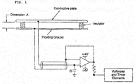
- the measurement plate of the conventional charge plate monitor includes a conductive plate, a floating ground that is separated from an earth ground, and an insulator provided between the conductive plate and the floating ground.
- an equivalent capacitance (for example, capacitance of 20 pF ⁇ 2 pF) needs to be formed in the measurement plate by using a voltage follower separating the conductive plate and the floating ground from each other.
- a high voltage cable is required. Therefore, this case has a disadvantage that selection of a high voltage cable is critically important.
- noncontact type measurement when a high voltage is applied, mechanical connection and subsequent perfect separation need to be performed. This case has a disadvantage that a mechanical device influencing the weight and size of the conventional charge plate monitor needs to be used.
- the present invention is provided to solve the problems described above and is intended to provide a charge plate monitor capable of eliminating a stray capacitor in a relay switch using a voltage feedback method, and an operation method thereof.
- a charge plate monitor including: a measurement plate unit including a conductive plate, a ground surface, and an insulator provided between the conductive plate and the ground surface; a noncontact electrometer installed between the conductive plate and the ground surface of the measurement plate unit, and detecting an electrical potential of the conductive plate; a measurement unit reading or passing the electrical potential of the conductive plate detected by the noncontact electrometer; and a voltage feedback circuit unit feeding the electrical potential of the conductive plate, which is passed by the measurement unit, back, and applying the electrical potential of the conductive plate to a terminal of a relay switch terminal.
- the charge plate monitor further includes a high voltage power supply (HVPS) having a power application portion that is combined with the measurement plate unit.
- HVPS high voltage power supply
- the noncontact electrometer may measure an electrical potential of the conductive plate when the HVPS applies a high voltage to the measurement plate unit via the relay switch.
- the voltage feedback circuit unit makes an electric current zero(0) by applying the electrical potential of the conductive plate, which is detected by the noncontact electrometer, to the terminal of the relay switch, thereby preventing the measurement plate unit from being influenced by a stray capacitor even after the relay switch is switched off.
- the measurement unit in decay mode, the measurement unit generates an HVPS on signal and a relay switch on signal, applies the HVPS on signal and the relay switch on signal to the HVPS and the relay switch, respectively.
- the HVPS supplies a voltage to the relay switch in accordance with the HVPS on signal applied by the measurement unit.
- the relay switch is switched on in accordance with the relay switch on signal applied by the measurement unit, and charges the conductive plate to a voltage equal to or higher than a predetermined value using a voltage supplied by the HVPS.
- the noncontact electrometer applies the electrical potential of the conductive plate, which is detected when the voltage supplied by the HVPS is equal to or higher than a predetermined value, to the measurement unit.
- the measurement unit generates a relay switch off signal when the voltage supplied by the HVPS is equal to or higher than a predetermined value, generates an HVPS off signal when the voltage supplied by the HVPS is equal to or lower than a predetermined value, and transmits the relay switch off signal and the HVPS off signal to the relay switch and the HVPS, respectively.
- the HVPS switches off a voltage supply to the relay switch in accordance with the HVPS off signal applied by the measurement unit.
- the relay switch is switched off in accordance with the relay switch off signal applied by the measurement unit, thereby switching off the voltage supply from the HVPS.
- the measurement unit reads a value of the electrical potential of the conductive plate detected by the noncontact electrometer when the voltage supplied by the HVPS is equal to or higher than a predetermined value, and feeds the read value of the electrical potential of the conductive plate back through the voltage feedback circuit unit, thereby following the voltage supplied by the HVPS.
- the measurement unit traces the voltage supplied by the HVPS by feeding the value of the electrical potential of the conductive plate back through the voltage feedback circuit unit, and thus equalizes potentials at respective ends of the relay switch.
- a method of operating a charge plate monitor including: detecting an electrical potential of a conductive plate, using a noncontact electrometer provided between the conductive plate and a ground surface of a measurement plate unit; reading or passing the electrical potential of the conductive plate, which is detected by the noncontact electrometer, using a measurement unit; and feeding the electrical potential of the conductive plate, which is passed by the measurement unit, back and applying the electrical potential of the conductive plate, which is passed by the measurement unit, to a terminal of a relay switch.
- the present invention has advantages described below.
- the charge plate monitor and operation method thereof in which a plate assembly is provided with a high voltage generator and a stray capacitor in a relay switch is eliminated through a voltage feedback method, are provided. For this reason, it becomes unnecessary to use a high voltage cable.
- it is possible to maintain an equivalent capacitance for example, capacitance of 20 pF ⁇ 2 pF
- an equivalent capacitance for example, capacitance of 20 pF ⁇ 2 pF
- the present invention it is possible to minimize influence of a stray capacitance in a charge plate monitor for measuring performance of an industrial ionizer. Therefore, the present invention has an advantage of precisely measuring a decay time of an industrial ionizer.
- a high voltage application portion is combined with a measurement plate unit. Therefore, an overall size of a measuring instrument main body (controller) can be reduced and the structure of the measuring instrument main body (controller) can be simplified. Furthermore, since the measuring instrument main body (controller) and the measurement plate unit are connected via a signal line, it is easy to choose a cable.
- a voltage feedback circuit unit when applying a high voltage to the measurement plate unit of the charge plate monitor, a voltage feedback circuit unit is used.
- the electrical potential of the conductive plate is detected by the noncontact electrometer and the same voltage is applied to the terminal of the relay switch, so an electric current becomes zero.
- the charge plate monitor is hardly influenced by a stray capacitor even after the relay switch is switched off.
- first, second, etc. may be used herein to describe various elements, these elements should not be limited by these terms. These terms are only used to distinguish one element from another element. For instance, a first element discussed below could be termed a second element without departing from the teachings of the present invention. Similarly, the second element could also be termed the first element.
- first element discussed below could be termed a second element without departing from the teachings of the present invention.
- second element could also be termed the first element.
- it will be understood that when an element is referred to as being “coupled” or “connected” to another element, it can be directly coupled or connected to the other element or intervening elements may be present therebetween. In contrast, it should be understood that when an element is referred to as being “directly coupled” or “directly connected” to another element, there are no intervening elements present.
- Other expressions that explain the relationship between elements, such as “between”, “directly between,”, “adjacent to”, or “directly adjacent to” should be construed
- FIG. 2 is a diagram illustrating a charge plate monitor according to one embodiment of the present invention.
- a charge plate monitor 100 includes a measurement plate unit 110, a noncontact electrometer 120, a measurement unit 130, and a voltage feedback circuit unit 140.
- the measurement plate unit 110 is a conductive plate.
- the measurement plate unit 110 includes a conductive plate 111 and a ground surface 112 that are conductive plates, and an insulator 113 provided between the conductive plate 111 and the grounded surface.
- the noncontact electrometer 120 is installed inside (i.e., between the conductive plate 111 and the ground surface 112).
- the conductive plate 111 may have a size of 10 to 25 cm x 10 to 25cm (preferably, 15 cm (6") x 15 cm (6")).
- the noncontact electrometer 120 is installed inside the measurement plate unit 110 (i.e., between the conductive plate 111 and the ground surface 112), detects a electrical potential of the measurement plate unit 110 (conductive plate 111), and applies the detected electrical potential of the conductive plate to the measurement unit 130.
- the measurement unit 130 is a combination of a field meter and a digital-to-analog (DAC) converter.
- the measurement unit 130 reads the electrical potential of the conductive plate transmitted by the noncontact electrometer 120, and passes the electrical potential of the conductive plate transmitted by the noncontact electrometer 120 to the voltage feedback circuit unit 140.
- DAC digital-to-analog
- the voltage feedback circuit unit 140 feeds the electrical potential of the conductive plate passed by the measurement unit 130 back, and applies the electrical potential of the conductive plate to a terminal of a relay switch, thereby causing an electric current to become zero (0).
- the voltage feedback circuit unit 140 feeds the electrical potential of the conductive plate passed by the measurement unit 130 back, and applies the electrical potential of the conductive plate to a terminal of a relay switch, thereby causing an electric current to become zero (0).
- the charge plate monitor 100 having the construction described above includes a high voltage power supply (HVPS) provided in a plate assembly.
- HVPS high voltage power supply
- the charge plate monitor 100 eliminates a stray capacitor in the relay switch by using the voltage feedback circuit unit 14. Therefore, it is unnecessary to use a high voltage cable and it is possible to maintain an equivalent capacitance (for example, capacitance of 20 pF ⁇ 2 pF) by minimizing a stray capacitance. For this reason, it is possible to prevent the stray capacitance from influencing measurements such as a static decay time when application of a high voltage is switched on and off by the relay switch. Therefore, it is possible to precisely evaluate performance of an ionizer.
- HVPS high voltage power supply
- the charge plate monitor 100 having the construction described above can be used as a measurement device for measuring a static elimination performance of an industrial ionizer.
- the charge plate monitor 100 can precisely measure a decay time of an industrial ionizer by minimizing influence of a stray capacitor.
- a high voltage application portion of the HVPS is combined with the measurement plate unit 110.
- This design reduces an overall size of the measurement unit 130 and simplifies the structure of the measurement plate unit 110.
- the measurement unit 130 and the measurement plate unit 110 are connected by a signal line, it is easy to choose a cable for connection therebetween.
- the charge plate monitor 100 having the construction described above detects an electrical potential of the conductive plate 111 using the noncontact electrometer 120 when applying a high voltage to the measurement plate unit 110 using the HVPS, and makes an electric current become zero (0) by using the voltage feedback circuit unit 140 that applies the detected electrical potential of the conductive plate to a terminal of the relay switch. Therefore, it is possible to prevent a stray capacitor influencing on measurements even after the relay switch is switched off. In addition, since it is possible to maintain an equivalent capacitance (for example, capacitance of 20 pF ⁇ 2 pF) as the plate capacitance, influence of the stray capacitor on measurements such as a natural discharge time can be prevented.
- an equivalent capacitance for example, capacitance of 20 pF ⁇ 2 pF
- the charge plate monitor 100 having the construction described above can be used to minimize influence of a stray capacitor in a circuit unit that applies a voltage by using a relay switch, or can be used for a product requiring a high insulation resistance.
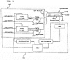
- FIG. 3 is a diagram illustrating the voltage feedback circuit unit of FIG. 2 .
- a main controller (not illustrated) in the measurement unit 130 in decay mode, generates an HVPS on signal (for example, a plus HVPS on signal (HVPS ON#1) or a minus HVPS on signal(HVPS ON#2)), and a relay switch on signal (for example, a plus relay switch on signal (+OUT ON#1) or a minus relay switch on signal (-OUT ON#2)), transmits the generated HVPS on signal (for example, the plus HVPS on signal(HVPS ON#1) or the minus HVPS on signal (HVPS ON#2)) to the plus HVPS or the minus HVPS, and transmits the generated relay switch on signal (for example, the plus relay switch on signal (+OUT ON#1) or the minus relay switch on signal (-OUT ON#2)) to the plus relay switch or the minus relay switch.
- HVPS on signal for example, a plus HVPS on signal (HVPS ON#1) or a minus HVPS on signal(HVPS ON#2)
- the plus HVPS and the minus HVPS apply different voltages to the plus relay switch and the minus relay switch, respectively in accordance with the HVPS on signals (for example, the plus HVPS on signal(HVPS ON#1) and the minus HVPS on signal(HVPS ON#2)) transmitted by the main controller.
- the HVPS on signals for example, the plus HVPS on signal(HVPS ON#1) and the minus HVPS on signal(HVPS ON#2) transmitted by the main controller.
- the plus relay switch or the minus relay switch is switched on in accordance with the relay switch on signal (for example, the plus relay switch on signal(+OUT ON#1) or the minus relay switch on signal (-OUT ON#2)) transmitted by the main controller, and charges the conductive plate to a voltage that is equal to or higher than a predetermined value (for example, 1050 V) by using the voltage supplied by the plus HVPS or the minus HVPS.
- the relay switch on signal for example, the plus relay switch on signal(+OUT ON#1) or the minus relay switch on signal (-OUT ON#2)
- a predetermined value for example, 1050 V
- the noncontact electrometer 120 detects an electrical potential of the measurement plate unit 110 (conductive plate 111) and applies the detected electrical potential of the conductive plate to the measurement unit 130. Specifically, when the voltage supplied by the plus HVPS or the minus HVPS is equal to or higher than a predetermined value (for example, 1050 V), the noncontact electrometer 120 transmits the electrical potential of the conductive plate to the measurement unit.
- a predetermined value for example, 1050 V
- the main controller of the measurement unit 130 when the voltages supplied by the plus HVPS and the minus HVPS are equal to or higher than a predetermined value (for example, 1050 V), the main controller of the measurement unit 130 generates relay switch off signals (for example, a plus relay switch off signal (+OUT OFF#1) and a minus relay switch off signal (-OUT OFF#2)). Meanwhile, when the electrical potential of the conductive plate is equal to or lower than a predetermined value (for example, 100 V), the main controller of the measurement unit 130 generates HVPS off signals (for example, a plus HVPS off signal (HVPS OFF#1) and a minus HVPS off signal (HVPS OFF#2)) for switching off the voltage supply from the plus HVPS and the minus HVPS.
- a predetermined value for example, 1050 V
- the main controller of the measurement unit 130 when the electrical potential of the conductive plate is equal to or lower than a predetermined value (for example, 100 V), the main controller of the measurement unit 130
- the main controller of the measurement unit 130 transmits the generated relay switch off signals (for example, the plus relay switch off signal (+OUT OFF#1) and the minus relay switch off signal(-OUT OFF#2)) to the plus relay switch and the minus relay switch, respectively, and transmits and the generated HVPS off signals (for example, the plus HVPS off signal (HVPS OFF#1) and the minus HVPS off signal (HVPS OFF#2)) to the plus HVPS and minus HVPS, respectively.
- the generated relay switch off signals for example, the plus relay switch off signal (+OUT OFF#1) and the minus relay switch off signal(-OUT OFF#2)
- HVPS off signals for example, the plus HVPS off signal (HVPS OFF#1) and the minus HVPS off signal (HVPS OFF#2)
- the plus HVPS and the minus HVPS switch off the voltage supply to the plus relay switch and the minus relay switch in accordance with the HVPS off signals (for example, the plus HVPS off signal(HVPS OFF#1) and the minus HVPS off signal(HVPS OFF#2)).
- the HVPS off signals for example, the plus HVPS off signal(HVPS OFF#1) and the minus HVPS off signal(HVPS OFF#2)).
- the plus relay switch and the minus relay switch are switched off in accordance with the relay switch off signals (for example, the plus relay switch off signal (+OUT OFF#1) and the minus relay switch off signal (-OUT OFF#2)) transmitted by the main controller, thereby switching off the voltage supply from the plus HVPS and the minus HVPS.
- the relay switch off signals for example, the plus relay switch off signal (+OUT OFF#1) and the minus relay switch off signal (-OUT OFF#2)
- the main controller of the measurement unit 130 reads the value of the electrical potential of the conductive plate detected by the noncontact electrometer 120 when the voltages supplied by the plus HVPS and the minus HVPS are equal to or higher than a predetermined value (for example, 1050 V), and feeds the read value of the electrical potential back via the voltage feedback circuit unit 140 until the read value of the electrical potential of the conductive plate drops to or below a predetermined value (for examples, 100 V).
- a predetermined value for example, 1050 V
- the present invention may not embodied only in the form of the device and/or operation method described above.
- the present invention can be implemented as a computer program for implementing functions corresponding to constituent elements of a specific embodiment, or a recording medium on which the program is recorded.
- Those skilled in the art can easily implement the present invention by referring to the description of the embodiments described above.
- preferred embodiments of the present invention have been described for illustrative purposes, the preferred embodiments are not intended to limit the scope of the present invention, and those ordinarily skilled in the art will appreciate that various modifications, additions and substitutions are possible, without departing from the scope and spirit of the present invention as disclosed in the accompanying claims.
Landscapes
- Physics & Mathematics (AREA)
- General Physics & Mathematics (AREA)
- Measurement Of Current Or Voltage (AREA)
- Elimination Of Static Electricity (AREA)
Applications Claiming Priority (2)
| Application Number | Priority Date | Filing Date | Title |
|---|---|---|---|
| KR1020150023803A KR101629915B1 (ko) | 2015-02-17 | 2015-02-17 | 챠지 플레이트 모니터링 장치 |
| PCT/KR2016/000011 WO2016133282A1 (fr) | 2015-02-17 | 2016-01-04 | Dispositif de surveillance de plaque de charge et son procédé de fonctionnement |
Publications (2)
| Publication Number | Publication Date |
|---|---|
| EP3260872A1 true EP3260872A1 (fr) | 2017-12-27 |
| EP3260872A4 EP3260872A4 (fr) | 2018-11-21 |
Family
ID=56191470
Family Applications (1)
| Application Number | Title | Priority Date | Filing Date |
|---|---|---|---|
| EP16752612.8A Withdrawn EP3260872A4 (fr) | 2015-02-17 | 2016-01-04 | Dispositif de surveillance de plaque de charge et son procédé de fonctionnement |
Country Status (6)
| Country | Link |
|---|---|
| US (1) | US10564190B2 (fr) |
| EP (1) | EP3260872A4 (fr) |
| JP (1) | JP6489335B2 (fr) |
| KR (1) | KR101629915B1 (fr) |
| CN (1) | CN107209216B (fr) |
| WO (1) | WO2016133282A1 (fr) |
Cited By (1)
| Publication number | Priority date | Publication date | Assignee | Title |
|---|---|---|---|---|
| US20210263110A1 (en) * | 2020-02-21 | 2021-08-26 | SK Hynix Inc. | Monitoring apparatus and system for an ionizer |
Families Citing this family (5)
| Publication number | Priority date | Publication date | Assignee | Title |
|---|---|---|---|---|
| KR102317486B1 (ko) | 2021-02-05 | 2021-10-28 | 주식회사 티엔에스솔루션 | 전위 감쇄 시간 측정기 |
| KR102493135B1 (ko) | 2021-02-18 | 2023-01-30 | 김선철 | 네트워크 기반의 소형 대전판을 가지는 챠지 플레이트 모니터링 장치 |
| KR102504492B1 (ko) * | 2021-03-29 | 2023-02-28 | (주)선재하이테크 | 정전하 측정 센서모듈 및 이를 이용한 정전하 모니터링 시스템 |
| KR102876190B1 (ko) | 2022-02-14 | 2025-10-24 | (주)엘케이원 | 다공성 차지 플레이트형 복합 성능 측정 장치 |
| CN116008640A (zh) * | 2022-12-15 | 2023-04-25 | 惠州联创达静电设备有限公司 | 平板离子检测仪 |
Family Cites Families (16)
| Publication number | Priority date | Publication date | Assignee | Title |
|---|---|---|---|---|
| US4797620A (en) * | 1986-08-20 | 1989-01-10 | Williams Bruce T | High voltage electrostatic surface potential monitoring system using low voltage A.C. feedback |
| US5016136A (en) * | 1989-02-17 | 1991-05-14 | Semtronics Corporation | Charge build-up and decay monitor |
| JP3149228B2 (ja) * | 1991-11-29 | 2001-03-26 | 株式会社リコー | 表面電位計 |
| US5432454A (en) * | 1994-03-10 | 1995-07-11 | Eastman Kodak Company | Apparatus and method to control free charge on moving webs |
| JPH09138255A (ja) * | 1995-11-14 | 1997-05-27 | Mita Ind Co Ltd | 電位検出装置およびそれに用いるセンサプローブ |
| JP3476069B2 (ja) | 1999-10-26 | 2003-12-10 | シャープ株式会社 | イオナイザの調整・評価装置 |
| US6826030B2 (en) * | 2002-09-20 | 2004-11-30 | Illinois Tool Works Inc. | Method of offset voltage control for bipolar ionization systems |
| JP3880945B2 (ja) * | 2003-04-15 | 2007-02-14 | アルプス電気株式会社 | 被測定物の帯電電位の評価方法及び評価装置 |
| JP2005077348A (ja) * | 2003-09-03 | 2005-03-24 | Sharp Corp | 除電性能評価装置及び除電性能評価方法 |
| CN101437602B (zh) | 2004-10-29 | 2011-04-06 | 特瑞克股份有限公司 | 离子平衡监视器 |
| JP4904133B2 (ja) * | 2006-10-03 | 2012-03-28 | シシド静電気株式会社 | 帯電モニタ装置およびイオン生成装置の性能評価方法 |
| JP2009110814A (ja) * | 2007-10-30 | 2009-05-21 | Sunx Ltd | 除電装置 |
| JP2012103056A (ja) | 2010-11-09 | 2012-05-31 | Hugle Electronics Inc | チャージプレートモニタ |
| US9588161B2 (en) * | 2010-12-07 | 2017-03-07 | Desco Industries, Inc. | Ionization balance device with shielded capacitor circuit for ion balance measurements and adjustments |
| TWI442069B (zh) * | 2011-04-27 | 2014-06-21 | Sharp Kk | High voltage inspection device |
| CN202141796U (zh) * | 2011-06-30 | 2012-02-08 | 北京市电力公司 | 带电显示装置的在线监视装置及在线验电装置 |
-
2015
- 2015-02-17 KR KR1020150023803A patent/KR101629915B1/ko active Active
-
2016
- 2016-01-04 US US15/550,977 patent/US10564190B2/en not_active Expired - Fee Related
- 2016-01-04 CN CN201680007464.2A patent/CN107209216B/zh active Active
- 2016-01-04 EP EP16752612.8A patent/EP3260872A4/fr not_active Withdrawn
- 2016-01-04 WO PCT/KR2016/000011 patent/WO2016133282A1/fr not_active Ceased
- 2016-01-04 JP JP2017561217A patent/JP6489335B2/ja active Active
Cited By (2)
| Publication number | Priority date | Publication date | Assignee | Title |
|---|---|---|---|---|
| US20210263110A1 (en) * | 2020-02-21 | 2021-08-26 | SK Hynix Inc. | Monitoring apparatus and system for an ionizer |
| US11733314B2 (en) * | 2020-02-21 | 2023-08-22 | SK Hynix Inc. | Monitoring apparatus and system for an ionizer |
Also Published As
| Publication number | Publication date |
|---|---|
| US10564190B2 (en) | 2020-02-18 |
| EP3260872A4 (fr) | 2018-11-21 |
| CN107209216B (zh) | 2019-11-19 |
| JP6489335B2 (ja) | 2019-03-27 |
| WO2016133282A1 (fr) | 2016-08-25 |
| CN107209216A (zh) | 2017-09-26 |
| KR101629915B1 (ko) | 2016-06-13 |
| US20180031615A1 (en) | 2018-02-01 |
| JP2018505430A (ja) | 2018-02-22 |
Similar Documents
| Publication | Publication Date | Title |
|---|---|---|
| US10564190B2 (en) | Charge plate monitor and operating method thereof | |
| US10133413B2 (en) | Input state detection device | |
| US10228395B2 (en) | Non-contact voltage measurement device | |
| US10254313B2 (en) | Noncontact voltage measurement apparatus | |
| EP3118632A1 (fr) | Dispositif de mesure de tension sans contact | |
| CN105701441A (zh) | 指纹感测器的感测方法及电路 | |
| US9989577B2 (en) | Continuity inspection device | |
| CN102646930A (zh) | 除电装置及方法 | |
| JP2017223580A (ja) | 充放電装置 | |
| EP4191256B1 (fr) | Procédé et circuit de détection de fuite électrique | |
| JP2001035686A (ja) | 直流除電器 | |
| CN111771109B (zh) | 静电电容检测装置 | |
| WO2014155680A1 (fr) | Dispositif de mesure de tension | |
| MX2025004332A (es) | Pelicula inteligente para pantalla | |
| Takahashi et al. | Development of an ion measuring system for AC corona discharge | |
| KR20080010382A (ko) | 이온 컨트롤 센서 | |
| JP2014202907A (ja) | 平面表示装置及びその検査方法 | |
| US7378835B2 (en) | Interleaved differential multiplexer | |
| CN120188015A (zh) | 静电电容测定电路以及载荷检测装置 | |
| JP5605577B2 (ja) | 静電容量式タッチセンサ | |
| KR101602809B1 (ko) | 고전압 펄스 시험 시스템의 시스템 컴포넨트를 위한 장치 | |
| US10393686B2 (en) | Conductivity meter for measuring an electric conductivity of a liquid medium | |
| JP2015055589A (ja) | 静電容量計測装置、静電容量型面状センサ装置および静電容量型液位検出装置 | |
| CN120019262A (zh) | 测量装置以及载荷检测系统 | |
| CN118033295A (zh) | 静电测试系统及方法 |
Legal Events
| Date | Code | Title | Description |
|---|---|---|---|
| STAA | Information on the status of an ep patent application or granted ep patent |
Free format text: STATUS: THE INTERNATIONAL PUBLICATION HAS BEEN MADE |
|
| PUAI | Public reference made under article 153(3) epc to a published international application that has entered the european phase |
Free format text: ORIGINAL CODE: 0009012 |
|
| STAA | Information on the status of an ep patent application or granted ep patent |
Free format text: STATUS: REQUEST FOR EXAMINATION WAS MADE |
|
| 17P | Request for examination filed |
Effective date: 20170727 |
|
| AK | Designated contracting states |
Kind code of ref document: A1 Designated state(s): AL AT BE BG CH CY CZ DE DK EE ES FI FR GB GR HR HU IE IS IT LI LT LU LV MC MK MT NL NO PL PT RO RS SE SI SK SM TR |
|
| AX | Request for extension of the european patent |
Extension state: BA ME |
|
| DAV | Request for validation of the european patent (deleted) | ||
| DAX | Request for extension of the european patent (deleted) | ||
| A4 | Supplementary search report drawn up and despatched |
Effective date: 20181018 |
|
| RIC1 | Information provided on ipc code assigned before grant |
Ipc: H05F 3/00 20060101ALI20181012BHEP Ipc: G01R 31/00 20060101ALI20181012BHEP Ipc: G01R 29/12 20060101AFI20181012BHEP Ipc: H01T 23/00 20060101ALI20181012BHEP Ipc: H01H 47/22 20060101ALI20181012BHEP |
|
| GRAP | Despatch of communication of intention to grant a patent |
Free format text: ORIGINAL CODE: EPIDOSNIGR1 |
|
| STAA | Information on the status of an ep patent application or granted ep patent |
Free format text: STATUS: GRANT OF PATENT IS INTENDED |
|
| INTG | Intention to grant announced |
Effective date: 20220225 |
|
| STAA | Information on the status of an ep patent application or granted ep patent |
Free format text: STATUS: THE APPLICATION IS DEEMED TO BE WITHDRAWN |
|
| 18D | Application deemed to be withdrawn |
Effective date: 20220708 |