EP3260897A1 - Medizinische beobachtungsvorrichtung und objektivtubus für medizinische beobachtungsvorrichtung - Google Patents
Medizinische beobachtungsvorrichtung und objektivtubus für medizinische beobachtungsvorrichtung Download PDFInfo
- Publication number
- EP3260897A1 EP3260897A1 EP15882757.6A EP15882757A EP3260897A1 EP 3260897 A1 EP3260897 A1 EP 3260897A1 EP 15882757 A EP15882757 A EP 15882757A EP 3260897 A1 EP3260897 A1 EP 3260897A1
- Authority
- EP
- European Patent Office
- Prior art keywords
- unit
- barrel
- medical observation
- eccentric
- observation device
- Prior art date
- Legal status (The legal status is an assumption and is not a legal conclusion. Google has not performed a legal analysis and makes no representation as to the accuracy of the status listed.)
- Withdrawn
Links
Images








Classifications
-
- G—PHYSICS
- G02—OPTICS
- G02B—OPTICAL ELEMENTS, SYSTEMS OR APPARATUS
- G02B7/00—Mountings, adjusting means, or light-tight connections, for optical elements
- G02B7/02—Mountings, adjusting means, or light-tight connections, for optical elements for lenses
- G02B7/021—Mountings, adjusting means, or light-tight connections, for optical elements for lenses for more than one lens
-
- A—HUMAN NECESSITIES
- A61—MEDICAL OR VETERINARY SCIENCE; HYGIENE
- A61B—DIAGNOSIS; SURGERY; IDENTIFICATION
- A61B90/00—Instruments, implements or accessories specially adapted for surgery or diagnosis and not covered by any of the groups A61B1/00 - A61B50/00, e.g. for luxation treatment or for protecting wound edges
- A61B90/36—Image-producing devices or illumination devices not otherwise provided for
- A61B90/361—Image-producing devices, e.g. surgical cameras
-
- G—PHYSICS
- G02—OPTICS
- G02B—OPTICAL ELEMENTS, SYSTEMS OR APPARATUS
- G02B1/00—Optical elements characterised by the material of which they are made; Optical coatings for optical elements
- G02B1/04—Optical elements characterised by the material of which they are made; Optical coatings for optical elements made of organic materials, e.g. plastics
-
- G—PHYSICS
- G02—OPTICS
- G02B—OPTICAL ELEMENTS, SYSTEMS OR APPARATUS
- G02B7/00—Mountings, adjusting means, or light-tight connections, for optical elements
- G02B7/003—Alignment of optical elements
-
- G—PHYSICS
- G02—OPTICS
- G02B—OPTICAL ELEMENTS, SYSTEMS OR APPARATUS
- G02B7/00—Mountings, adjusting means, or light-tight connections, for optical elements
- G02B7/02—Mountings, adjusting means, or light-tight connections, for optical elements for lenses
- G02B7/028—Mountings, adjusting means, or light-tight connections, for optical elements for lenses with means for compensating for changes in temperature or for controlling the temperature; thermal stabilisation
-
- G—PHYSICS
- G02—OPTICS
- G02B—OPTICAL ELEMENTS, SYSTEMS OR APPARATUS
- G02B7/00—Mountings, adjusting means, or light-tight connections, for optical elements
- G02B7/02—Mountings, adjusting means, or light-tight connections, for optical elements for lenses
- G02B7/04—Mountings, adjusting means, or light-tight connections, for optical elements for lenses with mechanism for focusing or varying magnification
- G02B7/08—Mountings, adjusting means, or light-tight connections, for optical elements for lenses with mechanism for focusing or varying magnification adapted to co-operate with a remote control mechanism
-
- G—PHYSICS
- G02—OPTICS
- G02B—OPTICAL ELEMENTS, SYSTEMS OR APPARATUS
- G02B7/00—Mountings, adjusting means, or light-tight connections, for optical elements
- G02B7/02—Mountings, adjusting means, or light-tight connections, for optical elements for lenses
- G02B7/04—Mountings, adjusting means, or light-tight connections, for optical elements for lenses with mechanism for focusing or varying magnification
- G02B7/10—Mountings, adjusting means, or light-tight connections, for optical elements for lenses with mechanism for focusing or varying magnification by relative axial movement of several lenses, e.g. of varifocal objective lens
-
- H—ELECTRICITY
- H04—ELECTRIC COMMUNICATION TECHNIQUE
- H04N—PICTORIAL COMMUNICATION, e.g. TELEVISION
- H04N23/00—Cameras or camera modules comprising electronic image sensors; Control thereof
- H04N23/50—Constructional details
- H04N23/55—Optical parts specially adapted for electronic image sensors; Mounting thereof
-
- H—ELECTRICITY
- H04—ELECTRIC COMMUNICATION TECHNIQUE
- H04N—PICTORIAL COMMUNICATION, e.g. TELEVISION
- H04N23/00—Cameras or camera modules comprising electronic image sensors; Control thereof
- H04N23/60—Control of cameras or camera modules
Definitions
- the present technology relates to a technical field for a medical observation device used in a medical field and including a barrel unit having an imaging optical system configured to acquire an image of an object and an element unit including an imaging element and for a lens barrel of the medical observation device.
- a medical observation device for practice such as operation, medical treatment, and examination in medical institutions such as a hospital, a medical observation device has been proposed, which is configured to enhance a treatment efficiency by observation of an affected area of a patient.
- a medical observation device is attached to, e.g., a tip end portion of a robot arm, and is used such that the arm is operated to set the medical observation device to a necessary direction or angle. This allows observation of the affected area of the patient from a desired direction.
- the medical observation device is used with a practitioner gripping the medical observation device.
- An image or a video acquired by the medical observation device is displayed on a display section such as a monitor or a display.
- This medical observation device includes, for example, a medical observation device including an imaging optical system configured to acquire an image of an object and an imaging element configured to photoelectrically convert the image of the object acquired by the imaging optical system.
- a medical observation device is configured such that the imaging optical system is disposed in a housing, the imaging element is held by an element holder, and the housing and the element holder are linked together (see, e.g., Patent Documents 1 and 2).
- the medical observation device is used for the practice such as operation, medical treatment, and examination, and therefore, sterilization processing called "autoclaving" is performed before treatment.
- Autoclaving is performed in a manner that the medical observation device is left for about 10 minutes under a high temperature of equal to or higher than 100°C, for example.
- the medical observation device needs to be configured to resist high temperature.
- the housing is made of a metal material to ensure heat resistance, this poses a problem for weight reduction of the medical observation device.
- the medical observation device is gripped by the practitioner upon use, it is extremely important to reduce the weight.
- the housing in which the imaging optical system and the element holder configured to hold the imaging element are preferably made of a material which exhibits heat resistance against autoclaving and by which weight reduction can be realized.
- the element holder needs to be made of a material suitable for the adhesive etc. for ensuring favorable performance of the imaging element.
- a medical observation device and a lens barrel of the medical observation device according to the present technology are intended to overcome the above-described problems and to realize weight reduction while ensuring favorable performance of an imaging element.
- a lens barrel of a medical observation device includes: a barrel unit including an imaging optical system configured to acquire an image of an object, and a housing in which the imaging optical system is disposed; and an element unit including an imaging element configured to photoelectrically convert the image of the object acquired by the imaging optical system, and an element holder configured to hold the imaging element, in which the housing is made of a resin material, and the element holder is made of a material different from that of the housing.
- the housing in which the imaging optical system is disposed is made of the resin material, and the element holder configured to hold the imaging element is made of the material different from that of the housing.
- a movable frame is provided, which is configured to hold at least one of the lenses and move in an optical axis direction, and the movable frame is made of a resin material.
- the movable frame configured to hold the lens and move in the optical axis direction is made of the resin material.
- a drive shaft whose axial direction is along the optical axis direction, and a guide shaft disposed parallel to the drive shaft are further provided, the movable frame is supported by the drive shaft and the guide shaft, and the movable frame is, using drive force transferred from the drive shaft, guided and moved by the guide shaft.
- At least two eccentric pins for positioning of the barrel unit and the element unit in a plane perpendicular to the optical axis direction is further provided, at least two pin insertion holes are formed at the barrel unit, at least two pin insertion through-holes are formed at the element unit, a portion of each eccentric pin is inserted into a corresponding one of the pin insertion holes, and another portion of each eccentric pin is inserted into a corresponding one of the pin insertion through-holes, at least one of the eccentric pins is rotated in a direction about an axis such that a position of the element unit with respect to the barrel unit is adjusted, and at least one of the pin insertion through-holes is formed in an elongated-hole shape.
- each eccentric pin includes an insertion shaft portion to be inserted into a corresponding one of the pin insertion through-hole, and an eccentric shaft portion which is to be inserted into a corresponding one of the pin insertion holes and which is provided eccentric with respect to the insertion shaft portion, and an eccentric amount of the eccentric shaft portion with respect to the insertion shaft portion is identical among all of the eccentric pins.
- the barrel unit and the element unit are, in the optical axis direction, linked together with a fastening screw.
- the barrel unit and the element unit are linked together by the fastening screw with positioning of the barrel unit and the element unit being held.
- a retainer spring configured to push the element unit against the barrel unit is supported on the fastening screw.
- the retainer spring expands/contracts when the barrel unit or the element unit expands or contracts due to the change in external environment.
- a screw hole into which the fastening screw is to be screwed is formed at the barrel unit, a screw insertion hole into which the fastening screw is to be inserted is formed at the element unit, and a diameter of the screw insertion hole is larger than that of the fastening screw.
- the fastening screw displaces relative to the screw insertion hole when the barrel unit or the element unit expands or contracts due to the external environment.
- a medical observation device includes: a barrel unit including an imaging optical system configured to acquire an image of an object, and a housing in which the imaging optical system is disposed; and an element unit including an imaging element configured to photoelectrically convert the image of the object acquired by the imaging optical system, and an element holder configured to hold the imaging element, in which the housing is made of a resin material, and the element holder is made of a material different from that of the housing.
- the housing in which the imaging optical system is disposed is made of the resin material, and the element holder configured to hold the imaging element is made of the material different from that of the housing.
- the housing in which the imaging optical system is disposed is made of the resin material while the element holder configured to hold the imaging element is made of the material different from that of the housing.
- a medical observation device of the mode described below is a medical observation device configured so that a moving image or a still image can be shot, and is configured such that a direction connecting between a lens and an imaging element is an optical axis direction.
- the optical axis direction indicates a front-to-back direction
- predetermined directions perpendicular to the optical axis direction respectively indicate an upper-to-lower direction and a right-to-left direction.
- description will be made in a state in which an object side is a front side and a direction in which an object image is taken is a back side.
- front-to-back, upper-to-lower, and right-to-left directions described below are set forth for the sake of description, and implementation of the present technology is not limited to these directions.
- a lens group described below may include a lens group having one or more lenses, and a lens group having these one or more lenses and other optical elements such as a diaphragm and an iris.
- a medical observation device 100 is configured such that a lens barrel 2 is disposed in an outer casing 1.
- the outer casing 1 is made of a metal material such as titanium.
- the outer casing 1 includes a recessed case body 3 opening on the back side, and a shallow recessed cover body 4 opening on the front side.
- the outer casing 1 is configured such that the case body 3 and the cover body 4 are linked together in the front-to-back direction.
- the outer casing 1 has the function of protecting the lens barrel 2, as well as functioning as a grip portion gripped by a practitioner.
- a manual focus ring 5 is rotatably supported at a front end portion of the case body 3.
- the manual focus ring 5 is manually operated so that a movable frame and a focus lens as described later can move in the optical axis direction (the front-to-back direction) to manually perform manual focusing.
- An insertion portion 6 in which a not-shown relay lens is disposed is attached to the front end portion of the case body 3.
- the insertion portion 6 is inserted into, e.g., an affected area of a patient, and an image or a video of the affected area etc. is shot via the insertion portion 6 by the lens barrel 2.
- the shot image or video is displayed on a not-shown monitor, and the practitioner performs treatment while checking the image or the video displayed on the monitor.
- An insertion hole 4a is formed at a back surface portion of the cover body 4.
- a not-shown cable for power supply to the lens barrel 2 or transmission/reception of a signal for the image or the video formed by the lens barrel 2 is inserted into the insertion hole 4a.
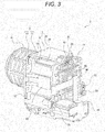
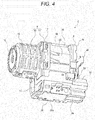
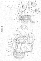
- the lens barrel 2 is configured such that a barrel unit 7 and an element unit 8 are linked together in the front-to-back direction (see Figs. 3 to 6 ).
- the barrel unit 7 includes a housing 9 and each of necessary portions such as an imaging optical system having a plurality of lenses arranged inside and outside the housing 9 as described later.
- the housing 9 is made of a resin material exhibiting excellent heat resistance, such as polyether sulphone (PES), and contains carbon.
- PES polyether sulphone
- the housing 9 is configured such that a front cabinet 10 and a back cabinet 11 are linked together in the front-to-back direction.
- the front cabinet 10 includes a plate-shaped base plate portion 12 facing the front-to-back direction, and a lens holding portion 13 protruding forward from a portion of the base plate portion 12 excluding a lower end portion thereof.
- the front cabinet 10 is formed in such a substantially cylindrical shape that the lens holding portion 13 penetrates the front cabinet 10 in the front-to-back direction.
- a plurality of lenses 14 are arranged in the optical axis direction (the front-to-back direction) in the lens holding portion 13, and are held by the lens holding portion 13.
- a diaphragm 15 is held at a front end portion of the lens holding portion 13.
- the back cabinet 11 is formed in a box shape opening on the front and lower sides.
- the back cabinet 11 includes a top surface portion 16 facing the upper-to-lower direction, a back surface portion 17 facing the front-to-back direction, side surface portions 18 facing the right-to-left direction, and an arrangement portion 19 protruding backward from a lower end portion of the back surface portion 17.
- the arrangement portion 19 is formed in a box shape opening on the lower side.
- Heat sinks 20 are attached respectively to outer surfaces of the top surface portion 16 and the side surface portions 18. For example, two heat sinks 20 are attached to the top surface portion 16, and a single heat sink 20 is attached to each side surface portion 18. Heat is released from the heat sinks 20, and therefore, a temperature increase at each portion of the housing 9 is suppressed in a temperature increase. Particularly in driving of the element unit 8, the amount of heat transferred from the later-described imaging element of the element unit 8 to the back cabinet 11 is great, and a temperature increase at each portion of the housing 9 is suppressed by heat release from the heat sinks 20 in driving of the element unit 8 while a stable driving state of the imaging element is ensured.
- the housing 9 contains carbon, and therefore, high heat conductivity of the housing 9 is ensured while the strength of the housing 9 is improved.
- An arrangement recessed portion 21 opening on the back side is formed on an upper end side of the back surface portion 17, and a transmission hole 22 is formed to penetrate a portion forming the arrangement recessed portion 21 in the front-to-back direction.
- a communication hole 23 is formed at a position closer to a lower end of the back surface portion 17, and allows communication between an internal space 11a as a space of the housing 9 on the front side of the back surface portion 17 and an internal space of the arrangement portion 19.
- Screw holes 24 are formed at an outer peripheral portion of the back surface portion 17. The screw holes 24 open on the back side.
- a first pin insertion hole 25 and a second pin insertion hole 26 each opening on the back side are formed at the back surface portion 17.
- the first pin insertion hole 25 is formed in a circular shape, and is positioned at an upper end portion of the back surface portion 17, for example.
- the second pin insertion hole 26 is also formed in a circular shape, and is positioned at one side portion of the back surface portion 17 below the first pin insertion hole 25, for example.
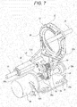
- Guide shafts 27 made of a metal material are arranged in the internal space 11a of the back cabinet 11 (see Figs. 6 to 8 ).
- the guide shafts 27 are arranged respectively at upper and lower end portions of the internal space 11a, and both end portions of each guide shaft 27 in an axis direction thereof are attached respectively to the lens holding portion 13 and the back surface portion 17.
- the attachment plate 28 is attached to a lower end portion of the back cabinet 11.
- the attachment plate 28 includes a coupling surface portion 28a facing the upper-to-lower direction and extending in the upper-to-lower direction, a support surface portion 28b protruding upward from a front end portion of the coupling surface portion 28a, and an attachment surface portion 28c protruding upward from a back end portion of the coupling surface portion 28a.
- the attachment surface portion 28c is positioned at a front end portion in the arrangement portion 19, and the support surface portion 28b is positioned at a front end portion in the internal space 11a.
- a drive motor 29 is attached to a back surface of the attachment surface portion 28c of the attachment plate 28.
- the drive motor 29 is, e.g., a stepping motor, and is disposed at the arrangement portion 19.
- a drive shaft (an output shaft) of the drive motor 29 is provided as a lead screw 30.
- the lead screw 30 is positioned in the internal space 11a with the lead screw 30 penetrating the attachment surface portion 28c.
- a front end portion of the lead screw 30 is supported by the support surface portion 28b.
- the lead screw 30 is made of a metal material.
- the movable frame 31 is slidably supported by the guide shafts 27.
- the movable frame 31 is made of a resin material exhibiting excellent heat resistance, such as polyether sulphone.
- the movable frame 31 includes a lens holding portion 32 facing the front-to-back direction, a coupling protrusion 33 protruding backward from a lower end portion of the lens holding portion 32, a support shaft portion 34 linked to the coupling protrusion 33, and a sleeve portion 35 protruding backward from the coupling protrusion 33.
- a portion of the lens holding portion 32 excluding the lower end portion thereof is formed in an annular shape.
- the focus lens 36 made of a glass material is held, for example.
- a spring support piece 32a protruding backward is provided at a position closer to a lower end of the lens holding portion 32.
- the coupling protrusion 33 includes a protruding portion 33a protruding backward from the lens holding portion 32, and a linking protrusion 33b laterally protruding from a back end portion of the protruding portion 33a.
- the support shaft portion 34 is formed in a round shaft shape extending in the front-to-back direction. A front end portion of the support shaft portion 34 is linked to the lower end portion of the lens holding portion 32, and a back end portion of the support shaft portion 34 is linked to the linking protrusion 33b.
- the sleeve portion 35 is formed in a substantially cylindrical shape whose axial direction is along the front-to-back direction, and protrudes backward from the protruding portion 33a.
- the movable frame 31 is configured such that an upper end portion of the lens holding portion 32 and the sleeve portion 35 are each slidably supported by a corresponding one of the guide shafts 27, and can be guided by the guide shafts 27 to move in the optical axis direction (the front-to-back direction) together with the focus lens 36.
- the focus lens 36 is attached to the lens holding portion 32 with adhesives 37 (see Figs. 8 and 9 ).
- the adhesives 37 are made of a material which exhibits elasticity and whose bonding strength is less likely to decrease even under high temperature. Since the adhesives 37 are made of the material which exhibits elasticity and whose bonding strength is less likely to decrease even under high temperature, a difference in linear expansion between the movable frame 31 and the focus lens 36 is absorbed by the adhesives 37 when autoclaving for leaving the lens barrel 2 for about 10 minutes under a high temperature of equal to or higher than 100°C is performed, for example.
- the focus lens 36 can be held on the lens holding portion 32 with high position accuracy, and damage of the focus lens 36 and dropping of the focus lens 36 from the lens holding portion 32 due to impact caused by, e.g., dropping can be prevented.
- a biasing spring 38 and a nut member 39 arranged in the front-to-back direction are supported by the support shaft portion 34 (see Figs. 6 and 7 ).
- the biasing spring 38 is, e.g., a torsion coil spring, and has the function of biasing the nut member 39 backward and biasing the nut member 39 toward one side in a direction about the axis of the support shaft portion 34.
- the nut member 39 is made of a resin material exhibiting both of high heat resistance and high sliding properties, such as polybutylene terephthalate (PBT).
- PBT polybutylene terephthalate
- the nut member 39 includes a not-shown screwing protrusion screwed into a screw groove of the lead screw 30.
- the nut member 39 is biased toward one side in the direction about the axis of the support shaft portion 34 by the biasing spring 38. In this manner, the screwing protrusion is screwed into the lead screw 30 with the screwing protrusion being laterally pushed against the lead screw 30.
- the screwing protrusion of the nut member 39 is, by biasing force of the biasing spring 38, screwed into the lead screw 30 with the screwing protrusion being laterally pushed against the lead screw 30.
- the screwing protrusion of the nut member 39 can be reliably screwed into the lead screw 30.
- the guide shafts 27 and the lead screw 30 are made of the metal materials, and the movable frame 31 and the nut member 39 are made of the resin materials.
- the movable frame 31 and the focus lens 36 can be smoothly and reliably moved in the optical axis direction.
- the screwing protrusion of the nut member 39 is also, by the biasing force of the biasing spring 38, screwed into the lead screw 30 with the screwing protrusion being laterally pushed against the lead screw 30.
- a favorable screwing state of the nut member 39 into the lead screw 30 can be ensured.
- the nut member 39 is biased backward by the biasing spring 38.
- the screwing protrusion is screwed into the screw groove of the lead screw 30 with the screwing protrusion being pushed against the screw groove from an axial direction of the lead screw 30.
- occurrence of backlash can be reduced.
- the movable frame 31 holding the focus lens 36 and being movable in the optical axis direction is made of the resin material.
- the weight of the movable frame 31 is reduced, and smooth movement of the movable frame 31 and weight reduction of the lens barrel 2 can be realized.
- autofocusing is performed in such a manner that the focus lens 36 moves in the optical axis direction in association with movement of the movable frame 31. Since autofocusing is performed by moving the lightweight movable frame 31, the operation speed of autofocusing is improved, and therefore, improvement in responsibility in focusing operation and improvement in focusing accuracy can be realized.
- the movable frame 31 is supported by the lead screw 30 as the drive shaft and the guide shafts 27, and the movable frame 31 and the focus lens 36 are, by the drive force transferred from the lead screw 30, guided and moved by the guide shafts 27.
- a portion of the movable frame 31 excluding part of the sleeve portion 35 is positioned in the internal space 11a, and part of the sleeve portion 35 and the drive motor 29 are positioned in the arrangement portion 19 (see Fig. 6 ).
- the arrangement portion 19 is a portion protruding backward from the lower end portion of the back surface portion 17 of the back cabinet 11.
- An arrangement space 40 is formed on the back side of the back surface portion 17 above the arrangement portion 19, and the element unit 8, a substrate, etc. are arranged in the arrangement space 40 as described later.
- the arrangement space 40 is a space where the element unit 8 etc. as a configuration necessary for the lens barrel 2 are arranged.
- the arrangement portion 19 is provided below the arrangement space 40, and part of the sleeve portion 35 and the drive motor 29 are positioned in the arrangement portion 19.
- part of the sleeve portion 35 and the drive motor 29 are positioned on the back side with respect to the front cabinet 10.
- the size of the lens barrel 2 can be reduced, and therefore, the entire size of the medical observation device 100 can be also reduced.
- the practitioner can easily grasp the medical observation device 100 when the medical observation device 100 is used with the outer casing 1 being gripped by the practitioner, and therefore, gripping properties of the medical observation device 100 can be improved.
- the lens barrel 2 is configured such that the sleeve portion 35 and the drive motor 29 are positioned below the element unit 8.
- the movable frame 31 is formed in a vertically-elongated shape (see Figs. 8 and 9 ), and there is a probability that a weight balance of the movable frame 31 is deteriorated.
- the screwing protrusion of the nut member 39 is, by the biasing force of the biasing spring 38, screwed into the lead screw 30 with the screwing protrusion being laterally pushed against the lead screw 30.
- the element unit 8 is attached to the back surface portion 17 of the back cabinet 11, and is disposed in the arrangement space 40 (see Figs. 3 to 6 ).
- the element unit 8 includes an element holder 41 made of a resin material, and the imaging element 42 held with the imaging element 42 being attached to the element holder 41 with, e.g., an adhesive (see Figs. 5 , 10 , and 11 ) .
- the element holder 41 is made of the resin material different from that of the housing 9 of the barrel unit 7, such as epoxy resin exhibiting excellent mechanical strength and high heat resistance. Thus, the element holder 41 and the housing 9 are different from each other in a coefficient of linear expansion.
- the element holder 41 is formed in a substantially rectangular frame shape, and an internal space of the element holder 41 is formed as a through-hole 41a.
- the imaging element 42 is formed in a rectangular shape, and is attached to a back surface of the element holder 41 with, e.g., an epoxy-based adhesive with the imaging element 42 covering the through-hole 41a from the back side.
- a sealing rubber 43 formed in a substantially rectangular frame shape is attached to a front surface of the imaging element 42, and an infrared cut filter 44 is attached to a front surface of the sealing rubber 43.
- the sealing rubber 43 is attached to the imaging element 42 with part of the sealing rubber 43 being inserted into the through-hole 41a, and adhesion of dust etc. to the imaging element 42 is prevented by the sealing rubber 43.
- the infrared cut filter 44 is positioned immediately on the back side of the transmission hole 22 formed at the back surface portion 17 of the back cabinet 11.
- the substrate 45 is joined to a back surface of the imaging element 42 by, e.g., reflow (see Fig. 6 ).
- the substrate 45 is configured such that two rigid substrates exhibiting high stiffness are connected together by a flexible wiring board disposed with the flexible wiring board being folded between the rigid substrates.
- a flexible printed wiring board 46 is connected to the substrate 45.
- the flexible printed wiring board 46 is configured such that each portion thereof is bent (see
- Each portion is attached to, e.g., a back surface of the arrangement portion 19, a lower surface of the lens holding portion 13 of the front cabinet 10, etc., and is connected to a corresponding one of necessary portions.
- the flexible printed wiring board 46 is disposed with part of the flexible printed wiring board 46 being folded in the arrangement space 40, and a tip end portion of the folded portion is connected to the substrate 45.
- a cable inserted into the insertion hole 4a formed at the cover body 4 of the outer casing 1 is connected to the flexible printed wiring board 46, and power is supplied from an external power supply to each portion via the cable and the flexible printed wiring board 46, for example.
- the substrate 45 is, by reflow, joined to the imaging element 42 in the element unit 8.
- the element unit 8 is exposed to high temperature in a reflow furnace.
- the element holder 41 is made of the resin material exhibiting high heat resistance, and therefore, the element unit 8 is sufficiently adapted to reflow. Consequently, a favorable joint state of the substrate 45 to the imaging element 42 can be ensured without, e.g., deformation of the element holder 41.
- the epoxy-based adhesive used for attachment of the imaging element 42 to the element holder 41 also exhibits high heat resistance, and therefore, detachment of the imaging element 42 from the element holder 41 is not caused even upon reflow. Consequently, a favorable attachment state by bonding of the imaging element 42 to the element holder 41 can be ensured.
- the element holder 41 is made of the resin material exhibiting high compatibility with the epoxy-based adhesive used for attachment of the imaging element 42, and therefore, high bonding strength is obtained by the epoxy-based adhesive. Consequently, a favorable bonding state of the imaging element 42 to the element holder 41 can be ensured.
- a first pin insertion through-hole 47 and a second pin insertion through-hole 48 both penetrating the element holder 41 in the front-to-back direction are formed at the element holder 41 (see Fig. 5 ).
- the first pin insertion through-hole 47 is formed in a circular shape, and is positioned at a center portion of an upper end portion of the element holder 41 in the right-to-left direction, for example.
- the second pin insertion through-hole 48 is formed in an elongated-hole shape, and is positioned at one side portion of the element holder 41 below the first pin insertion through-hole 47, for example.
- the second pin insertion through-hole 48 is formed such that a longitudinal direction thereof is along a direction connecting between the first pin insertion through-hole 47 and the second pin insertion through-hole 48.
- the diameter of the first pin insertion through-hole 47 is larger than that of the first pin insertion hole 25 formed at the back surface portion 17 of the back cabinet 11, and the diameter (the width) of the second pin insertion through-hole 48 is larger than that of the second pin insertion hole 26 formed at the back surface portion 17 of the back cabinet 11.
- Adhesive reservoir recessed portions 49 opening on the back side are formed at the element holder 41, and are continuously positioned respectively at the first pin insertion through-hole 47 and the second pin insertion through-hole 48.
- Screw insertion holes 50 are formed to penetrate an outer peripheral portion of the element holder 41 in the front-to-back direction.
- the element unit 8 is linked to the barrel unit 7 by position adjustment using a first eccentric pin 51 and a second eccentric pin 52.
- the first eccentric pin 51 includes a circular-columnar insertion shaft portion 53 extending in the front-to-back direction, an eccentric shaft portion 54 protruding forward from a front surface of the insertion shaft portion 53, and an operation target portion 55 protruding backward from a back surface of the insertion shaft portion 53.
- An operation slit 55a is formed at the operation target portion 55.
- the eccentric shaft portion 54 is positioned eccentric with respect to the insertion shaft portion 53, and the center axis of the eccentric shaft portion 54 is shifted with respect to the center axis of the insertion shaft portion 53.
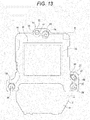
- the first eccentric pin 51 is inserted such that the insertion shaft portion 53 is inserted into the first pin insertion through-hole 47 from the back side and that the eccentric shaft portion 54 is inserted into the first pin insertion hole 25 from the back side (see Fig. 13 ).
- the positions of the screw holes 24 and the screw insertion holes 50 are exaggeratingly illustrated as a greatly-shifted state for the sake of easy understanding of description.
- the insertion shaft portion 53 and the eccentric shaft portion 54 are rotatably fitted respectively into the first pin insertion through-hole 47 and the first pin insertion hole 25.
- the second eccentric pin 52 includes a circular-columnar insertion shaft portion 56 extending in the front-to-back direction, an eccentric shaft portion 57 protruding forward from a front surface of the insertion shaft portion 56, and an operation target portion 58 protruding backward from a back surface of the insertion shaft portion 56.
- An operation slit 58a is formed at the operation target portion 58.
- the eccentric shaft portion 57 is positioned eccentric with respect to the insertion shaft portion 56, and the center axis of the eccentric shaft portion 57 is shifted with respect to the center axis of the insertion shaft portion 56.
- the eccentric amount of the eccentric shaft portion 54 with respect to the insertion shaft portion 53 of the first eccentric pin 51 is the same as that of the eccentric shaft portion 57 with respect to the insertion shaft portion 56 of the second eccentric pin 52.
- the second eccentric pin 52 is inserted such that the insertion shaft portion 56 is inserted into the second pin insertion through-hole 48 from the back side and that the eccentric shaft portion 57 is inserted into the second pin insertion hole 26 from the back side (see Fig. 13 ).
- the insertion shaft portion 56 is rotatably inserted into the second pin insertion through-hole 48, and the eccentric shaft portion 57 is rotatably fitted into the second pin insertion hole 26.
- the first eccentric pin 51 or the second eccentric pin 52 is rotated such that the position of the element unit 8 with respect to the barrel unit 7 is adjusted (see Fig. 14 ).
- the first eccentric pin 51 and the second eccentric pin 52 are each rotated by rotation of a not-shown jig, such as a screwdriver, inserted into each of the operation slits 55a, 58a.
- the position of the element unit 8 with respect to the barrel unit 7 is adjusted such that the optical axis of the imaging optical system of the barrel unit 7 and the center (the middle) of the imaging element 42 of the element unit 8 are coincident with each other. Such position adjustment is performed while the position of the barrel unit 7 and the position of the element unit 8 displayed on the monitor are being observed.
- the insertion shaft portion 53 rotates about the eccentric shaft portion 54 as a pivot point in an eccentric state. Then, the position of the first pin insertion through-hole 47 with respect to the first pin insertion hole 25 changes, and the position of the element unit 8 with respect to the barrel unit 7 changes. In this state, the second eccentric pin 52 rotates about the eccentric shaft portion 57 as a pivot point in association with rotation of the first eccentric pin 51.
- the insertion shaft portion 56 rotates about the eccentric shaft portion 57 as a pivot point in an eccentric state. Then, the position of the second pin insertion through-hole 48 with respect to the second pin insertion hole 26 changes, and the position of the element unit 8 with respect to the barrel unit 7 changes. In this state, the first eccentric pin 51 rotates about the eccentric shaft portion 54 as a pivot point in association with rotation of the second eccentric pin 52.
- the first eccentric pin 51 or the second eccentric pin 52 is rotated such that the position of the element unit 8 with respect to the barrel unit 7 changes, and adjustment of the position of the element unit 8 with respect to the barrel unit 7 is terminated when the optical axis of the imaging optical system and the center of the imaging element 42 become coincident with each other.
- the first eccentric pin 51 and the second eccentric pin 52 are used, the eccentric amount of the eccentric shaft portion 54 with respect to the insertion shaft portion 53 being the same as the eccentric amount of the eccentric shaft portion 57 with respect to the insertion shaft portion 56.
- the same eccentric pins may be used as the first eccentric pin 51 and the second eccentric pin 52. Consequently, the positions of the barrel unit 7 and the element unit 8 can be easily adjusted while the manufacturing cost of the lens barrel 2 can be reduced.
- the positions of the barrel unit 7 and the element unit 8 are adjusted, it is not necessary to preset, considering position shift between the imaging optical system and the imaging element 42, a smaller imaging area of the imaging element 42 as compared to an effective imaging area of the imaging element 42, and an image quality can be improved using the entirety of the effective imaging area of the imaging element 42 without the imaging area extending outside the effective imaging area.
- each adhesive reservoir recessed portion 49 is an adhesive rich in elasticity. Such an adhesive expands/contracts when the element holder 41 moves relative to the first eccentric pin 51 and the second eccentric pin 52 within a certain area, thereby preventing detachment of the element holder 41 from the first eccentric pin 51 and the second eccentric pin 52.
- the attachment body 59 includes a fastening screw 60, a retainer plate 61, and a retainer spring 62 (see Fig. 16 ).
- the fastening screw 60 includes a head portion 60a with a rotation operation groove, and a threaded shaft portion 60b protruding from the head portion 60a.
- the threaded shaft portion 60b is inserted into the screw insertion hole 50 of the element holder 41, and the diameter of the screw insertion holes 50 is larger than that of the threaded shaft portion 60b.
- the retainer plate 61 is formed in a ring shape, and the threaded shaft portion 60b of the fastening screw 60 is inserted into the retainer plate 61. Thus, the retainer plate 61 is movable relative to the threaded shaft portion 60b in an axial direction of the threaded shaft portion 60b.
- the retainer spring 62 is, e.g., a washer-shaped spring, and is disposed between the head portion 60a of the fastening screw 60 and the retainer plate 61 with the retainer spring 62 being supported by the threaded shaft portion 60b.
- the retainer spring 62 has the function of biasing the retainer plate 61 in a direction apart from the head portion 60a in the axial direction of the threaded shaft portion 60b.
- the threaded shaft portion 60b of the fastening screw 60 of each attachment body 59 is inserted into a corresponding one of the screw insertion holes 50 of the element holder 41 from the back side, and is screwed into a corresponding one of the screw holes 24 formed at the back surface portion 17 of the back cabinet 11.
- the threaded shaft portion 60b is screwed into the screw hole 24 such that the barrel unit 7 and the element unit 8 are linked together with positioning of the barrel unit 7 and the element unit 8 being made and that part of a front surface of the element holder 41 contacts part of a back surface of the barrel unit 7.
- part of the element unit 8 is disposed in the arrangement recessed portion 21 of the back surface portion 17.
- the fastening screw 60 is provided as a tapping screw.
- the fastening screws 60 are screwed into the back surface portion 17, and therefore, the barrel unit 7 and the element unit 8 can be linked together without changing a position relationship between the barrel unit 7 and the element unit 8.
- each fastening screw 60 is provided as the tapping screw and is screwed into the back surface portion 17.
- the screw holes 24 may be, without forming the screw holes 24 at the back surface portion 17 in advance, formed in such a manner that the fastening screws 60 are screwed into the back surface portion 17, or may be formed in such a manner that each fastening screw 60 is screwed into a hole formed in advance at the back surface portion 17 and having a smaller diameter than that of the threaded shaft portion 60b.
- the barrel unit 7 and the element unit 8 are, in the optical axis direction, linked together by the fastening screws 60 in a state in which positioning of the barrel unit 7 and the element unit 8 is made by the first eccentric pin 51 and the second eccentric pin 52.
- the barrel unit 7 and the element unit 8 are linked together by the fastening screws 60 with a positioning state of the barrel unit 7 and the element unit 8 being held, and detachment of the barrel unit 7 and the element unit 8 can be prevented in the positioning state.
- the retainer plates 61 contact the back surface of the element holder 41.
- the retainer plate 61 is, by the retainer spring 62, biased in the direction apart from the head portion 60a.
- the element holder 41 is pushed from the back side by the retainer plates 61, and closely contacts the back surface portion 17.
- the retainer spring 62 for pushing the element unit 8 against the barrel unit 7 is supported on the fastening screw 60, and therefore, the element unit 8 is pushed against the barrel unit 7 by the retainer springs 62 with the barrel unit 7 and the element unit 8 being linked together by the fastening screws 60.
- the retainer springs 62 expand/contract when the barrel unit 7 or the element unit 8 expands or contracts due to the change in external environment, and therefore, a favorable linking state of the barrel unit 7 and the element unit 8 can be ensured even in a state in which the barrel unit 7 or the element unit 8 expands or contracts.
- the housing 9 and the element holder 41 might expand or contract even in the plane perpendicular to the optical axis direction.
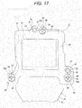
- the element unit 8 displaces relative to the barrel unit 7 in the plane perpendicular to the optical axis direction (see Fig. 17 ).
- the element unit 8 displaces relative to the barrel unit 7 with reference to the eccentric shaft portion 54 of the first eccentric pin 51, and the position of the elongated-hole-shaped second pin insertion through-hole 48 changes with respect to the insertion shaft portion 56 of the second eccentric pin 52.
- the second pin insertion through-hole 48 is formed in the elongated-hole shape, and therefore, displacement of the element unit 8 relative to the barrel unit 7 is allowed.
- the housing 9 and the element holder 41 can be each made of an optimal material for ensuring necessary performance. Consequently, functionality of the barrel unit 7 and the element unit 8 can be improved while favorable performance can be ensured.
- the housing 9 and the element holder 41 can be made of the optimal materials, considering heat resistance, strength, a cost, etc.
- functionality of the barrel unit 7 and the element unit 8 can be improved while the manufacturing cost of the lens barrel 2 can be reduced.
- the lens barrel 2 is, as described above, configured such that the longitudinal direction of the elongated-hole-shaped second pin insertion through-hole 48 is along the direction connecting between the first pin insertion through-hole 47 and the second pin insertion through-hole 48.
- the insertion shaft portion 56 of the second eccentric pin 52 is less likely to interfere with displacement of the element unit 8, and therefore, the element unit 8 can smoothly displace relative to the barrel unit 7.
- each screw insertion hole 50 of the element holder 41 is larger than that of a corresponding one of the threaded shaft portions 60b of the fastening screws 60.
- the threaded shaft portion 60b displaces relative to the screw insertion hole 50 when the barrel unit 7 or the element unit 8 expands or contracts in a direction perpendicular to the optical axis direction due to the external environment. Thus, the threaded shaft portion 60b does not contact the relatively-displaced element unit 8.
- the expanded or contracted barrel unit 7 and the element unit 8 return to original states, and return to original positioning states before the change in external environment.
- the housing 9 of the barrel unit 7 is made of the resin material
- the element holder 41 of the element unit 8 is made of the material different from that of the housing 9.
- the housing 9 in which the imaging optical system is disposed is made of the resin material, and the element holder 41 for holding the imaging element 42 is made of the material different from that of the housing 9. Consequently, weight reduction can be realized while favorable performance of the imaging element 42 can be ensured.
- the medical observation device 100 is gripped by the practitioner upon use, and therefore, practitioner's usability can be improved by weight reduction.
- the housing 9 and the element holder 41 are both made of the resin materials.
- the housing 9 and the element holder 41 can be easily formed in desired shapes as compared to metal materials, and the degree of freedom in designing can be improved.
- the housing 9 can be formed in the minimum possible size and shape according to the structure positioned in the housing 9, and therefore, size reduction can be realized.
- housing 9 and the element holder 41 are both made of the resin materials, manufacturing cost reduction can be realized.
- Fig. 18 illustrates a block diagram of one embodiment of the medical observation device of the present technology.
- a medical observation device 100 includes a lens barrel 80 (the lens barrel 2) having an imaging function, a camera signal processing section 81 configured to perform signal processing such as analog-to-digital conversion of a shot image signal, and an image processing section 82 configured to perform the processing of recording and reproducing the image signal.
- the medical observation device 100 includes a display section 83 configured to display, e.g., a shot image, a reader/writer (R/W) 84 configured to write the image signal in a memory 90 and read the image signal from the memory 90, a central processing unit (CPU) 85 configured to control the entirety of the medical observation device 100, an input operation section 86 such as various switches for which desired operation is made by a user, and a lens drive control section 87 configured to control driving of lenses arranged in the lens barrel 80.
- a display section 83 configured to display, e.g., a shot image
- a reader/writer (R/W) 84 configured to write the image signal in a memory 90 and read the image signal from the memory 90
- CPU central processing unit
- input operation section 86 such as various switches for which desired operation is made by a user
- a lens drive control section 87 configured to control driving of lenses arranged in the lens barrel 80.
- the lens barrel 80 includes, for example, an imaging optical system having a lens group 88 (lenses 14 and a focus lens 36), and an imaging element 89 (an imaging element 42) such as a charge coupled device (CCD) or a complementary metal-oxide semiconductor (CMOS).
- an imaging optical system having a lens group 88 (lenses 14 and a focus lens 36), and an imaging element 89 (an imaging element 42) such as a charge coupled device (CCD) or a complementary metal-oxide semiconductor (CMOS).
- CCD charge coupled device
- CMOS complementary metal-oxide semiconductor
- the camera signal processing section 81 is configured to perform various types of signal processing such as conversion of an output signal of the imaging element 89 into a digital signal, noise removal, image quality correction, and conversion into a brightness/color-difference signal.
- the image processing section 82 is configured to perform, e.g., compression coding processing or expansion decoding processing of the image signal based on a predetermined image data format and the processing of converting data specifications such as a definition.
- the display section 83 has the function of displaying various types of data such as the state of operation for the input operation section 86 by the user and the shot image. Note that the display section 83 is not necessarily provided at the medical observation device 100, and the medical observation device 100 may be configured such that an image is displayed after shot image data has been sent to other display units such as a monitor.
- the R/W 84 is configured to write the image data encoded by the image processing section 82 in the memory 90 and read the image data recorded in the memory 90.
- the CPU 85 functions as a control processing section configured to control each circuit block provided at the medical observation device 100, and is configured to control each circuit block on the basis of, e.g., an instruction input signal from the input operation section 86.
- the input operation section 86 is configured to output the instruction input signal corresponding to user's operation to the CPU 85.
- the lens drive control section 87 is configured to control, on the basis of a control signal from the CPU 85, a drive source (the drive motor 29) configured to drive the lens (the focus lens 36) of the lens group 88.
- the memory 90 is a semiconductor memory detachable from a slot connected to the R/W 84, for example.
- an image signal shot by the lens barrel 80 is output to the display section 83 via the camera signal processing section 81 under the control of the CPU 85, and is displayed as a camera-through image.
- the CPU 85 outputs the control signal to the lens drive control section 87, and a predetermined lens of the lens group 88 is moved on the basis of control of the lens drive control section 87.
- the shot image signal is output from the camera signal processing section 81 to the image processing section 82, and the compression encoding processing is performed for such a signal. Then, the resultant is converted into digital data in a predetermined data format. The converted data is output to the R/W 84, and is written in the memory 90.
- Focusing is performed in such a manner that the lens drive control section 87 moves the focus lens 36 of the lens group 88 on the basis of the control signal from the CPU 85.
- predetermined image data is read from the memory 90 by the R/W 84 according to the operation for the input operation section 86.
- a reproduction image signal is output to the display section 83, and a reproduction image is displayed.
- the present technology may have the following configurations.
Landscapes
- Physics & Mathematics (AREA)
- Optics & Photonics (AREA)
- General Physics & Mathematics (AREA)
- Health & Medical Sciences (AREA)
- Engineering & Computer Science (AREA)
- Surgery (AREA)
- Life Sciences & Earth Sciences (AREA)
- Multimedia (AREA)
- Signal Processing (AREA)
- Medical Informatics (AREA)
- Pathology (AREA)
- Oral & Maxillofacial Surgery (AREA)
- Biomedical Technology (AREA)
- Heart & Thoracic Surgery (AREA)
- Nuclear Medicine, Radiotherapy & Molecular Imaging (AREA)
- Molecular Biology (AREA)
- Animal Behavior & Ethology (AREA)
- General Health & Medical Sciences (AREA)
- Public Health (AREA)
- Veterinary Medicine (AREA)
- Lens Barrels (AREA)
- Studio Devices (AREA)
Applications Claiming Priority (2)
| Application Number | Priority Date | Filing Date | Title |
|---|---|---|---|
| JP2015029546 | 2015-02-18 | ||
| PCT/JP2015/086485 WO2016132656A1 (ja) | 2015-02-18 | 2015-12-28 | 医療用観察装置及び医療用観察装置のレンズ鏡筒 |
Publications (2)
| Publication Number | Publication Date |
|---|---|
| EP3260897A1 true EP3260897A1 (de) | 2017-12-27 |
| EP3260897A4 EP3260897A4 (de) | 2019-03-20 |
Family
ID=56692637
Family Applications (1)
| Application Number | Title | Priority Date | Filing Date |
|---|---|---|---|
| EP15882757.6A Withdrawn EP3260897A4 (de) | 2015-02-18 | 2015-12-28 | Medizinische beobachtungsvorrichtung und objektivtubus für medizinische beobachtungsvorrichtung |
Country Status (4)
| Country | Link |
|---|---|
| US (1) | US10274693B2 (de) |
| EP (1) | EP3260897A4 (de) |
| JP (1) | JP6822395B2 (de) |
| WO (1) | WO2016132656A1 (de) |
Families Citing this family (5)
| Publication number | Priority date | Publication date | Assignee | Title |
|---|---|---|---|---|
| JP6401427B1 (ja) * | 2016-12-19 | 2018-10-10 | オリンパス株式会社 | 医療用撮像装置 |
| JP7387257B2 (ja) * | 2018-09-21 | 2023-11-28 | オークマ株式会社 | ロボットユニット |
| JP2021173812A (ja) * | 2020-04-22 | 2021-11-01 | セイコーエプソン株式会社 | 投写光学装置およびプロジェクター |
| CN115281591B (zh) * | 2022-07-29 | 2025-08-01 | 杭州海康威视数字技术股份有限公司 | 一种医用手持摄像头及医用摄像设备 |
| CN116243446B (zh) * | 2023-05-05 | 2023-09-01 | 中国科学院西安光学精密机械研究所 | 一种超轻型柔性支撑光学系统及其装配方法 |
Family Cites Families (19)
| Publication number | Priority date | Publication date | Assignee | Title |
|---|---|---|---|---|
| JPS6069955A (ja) * | 1983-09-26 | 1985-04-20 | Fuji Xerox Co Ltd | 画像読取装置における撮像素子の位置調整機構 |
| JPS61259599A (ja) * | 1985-05-14 | 1986-11-17 | 松下電器産業株式会社 | 固体撮像素子の位置調整装置 |
| JP2850010B2 (ja) * | 1989-02-28 | 1999-01-27 | 池上通信機 株式会社 | Tvカメラの光軸調整装置 |
| JPH0538644U (ja) * | 1991-10-28 | 1993-05-25 | 富士写真光機株式会社 | 液晶パネルのアライメント調整機構 |
| JP2886032B2 (ja) | 1993-04-20 | 1999-04-26 | 株式会社ピーエフユー | 画像読取装置の光学調整機構 |
| US6292221B1 (en) * | 1998-11-17 | 2001-09-18 | Vista Medical Technologies, Inc. | Motorized focusing device and viewing system utilizing same |
| US6956610B1 (en) * | 1999-02-18 | 2005-10-18 | Linvatec Corporation | Shock mounting system for CCD camera |
| JP3860718B2 (ja) * | 2001-03-23 | 2006-12-20 | フジノン株式会社 | レンズ駆動装置 |
| JP3682026B2 (ja) * | 2002-02-01 | 2005-08-10 | オリンパス株式会社 | 内視鏡 |
| JP3831318B2 (ja) * | 2002-08-22 | 2006-10-11 | オリンパス株式会社 | 内視鏡用撮像装置 |
| JP2005006769A (ja) * | 2003-06-17 | 2005-01-13 | Olympus Corp | カプセル内視鏡 |
| JP4372152B2 (ja) * | 2004-03-17 | 2009-11-25 | 株式会社日本政策投資銀行 | 結像位置調整機構および撮影装置 |
| JP2007167125A (ja) * | 2005-12-19 | 2007-07-05 | Olympus Medical Systems Corp | カプセル内視鏡及びその製造方法 |
| CN102123654B (zh) * | 2008-11-11 | 2012-07-18 | 奥林巴斯医疗株式会社 | 摄像装置及内窥镜 |
| JP2011104068A (ja) | 2009-11-17 | 2011-06-02 | Panasonic Corp | 口腔内カメラ |
| JP2013056003A (ja) * | 2011-09-07 | 2013-03-28 | Olympus Medical Systems Corp | 撮像装置、内視鏡 |
| JP5450704B2 (ja) * | 2012-03-26 | 2014-03-26 | 株式会社フジクラ | 電気ケーブルおよび外筒付き撮像機構、内視鏡、電気ケーブルおよび外筒付き撮像機構の製造方法 |
| US9746636B2 (en) * | 2012-10-19 | 2017-08-29 | Cognex Corporation | Carrier frame and circuit board for an electronic device |
| WO2014203983A1 (ja) * | 2013-06-21 | 2014-12-24 | オリンパスメディカルシステムズ株式会社 | 内視鏡用撮像ユニット及び内視鏡装置 |
-
2015
- 2015-12-28 EP EP15882757.6A patent/EP3260897A4/de not_active Withdrawn
- 2015-12-28 US US15/550,665 patent/US10274693B2/en active Active
- 2015-12-28 WO PCT/JP2015/086485 patent/WO2016132656A1/ja not_active Ceased
- 2015-12-28 JP JP2017500306A patent/JP6822395B2/ja not_active Expired - Fee Related
Also Published As
| Publication number | Publication date |
|---|---|
| JP6822395B2 (ja) | 2021-01-27 |
| US10274693B2 (en) | 2019-04-30 |
| WO2016132656A1 (ja) | 2016-08-25 |
| JPWO2016132656A1 (ja) | 2017-11-24 |
| US20180031797A1 (en) | 2018-02-01 |
| EP3260897A4 (de) | 2019-03-20 |
Similar Documents
| Publication | Publication Date | Title |
|---|---|---|
| US10274693B2 (en) | Medical observation device and lens barrel of medical observation device | |
| CN115427860B (zh) | 超声驱动装置、摄像机模块及摄像机搭载装置 | |
| US7755859B2 (en) | Lens assembly of camera module | |
| CN101636693B (zh) | 成像设备 | |
| CN103533879B (zh) | 内窥镜用摄像单元 | |
| KR20080022051A (ko) | 손떨림 보정 기구 및 촬상 장치 | |
| CN101672980A (zh) | 内窥镜用摄像单元 | |
| WO2007135854A1 (ja) | レンズ駆動装置および撮像装置 | |
| US11153469B2 (en) | Modular optical recording system | |
| US20120182633A1 (en) | Lens drive mechanism, lens barrel, and imaging apparatus | |
| JP2012008335A (ja) | レンズ鏡筒 | |
| JP2011150136A (ja) | ブレ補正装置 | |
| JP6495555B1 (ja) | 光学ユニットおよび内視鏡 | |
| US20250036011A1 (en) | Optical system | |
| JP4445458B2 (ja) | レンズ駆動装置およびそれを用いた撮像装置 | |
| US12578621B2 (en) | Optical system | |
| WO2022134190A1 (zh) | 摄像装置用防振机构、光学系统、相机及电子设备 | |
| JP3994517B2 (ja) | カメラ用レンズ鏡筒 | |
| US10728433B2 (en) | Adjustable smartphone assembly for an optical device eyepiece | |
| CN104111526B (zh) | 内窥镜装置 | |
| US20140293461A1 (en) | Drive device, lens barrel and imaging apparatus | |
| CN115004101A (zh) | 光学防振装置、光学装置及磁传感器固定方法 | |
| JP2010214053A (ja) | 内視鏡の先端内蔵アクチュエータ | |
| JP5865928B2 (ja) | 内視鏡装置 | |
| JPWO2018079070A1 (ja) | 内視鏡 |
Legal Events
| Date | Code | Title | Description |
|---|---|---|---|
| STAA | Information on the status of an ep patent application or granted ep patent |
Free format text: STATUS: THE INTERNATIONAL PUBLICATION HAS BEEN MADE |
|
| PUAI | Public reference made under article 153(3) epc to a published international application that has entered the european phase |
Free format text: ORIGINAL CODE: 0009012 |
|
| STAA | Information on the status of an ep patent application or granted ep patent |
Free format text: STATUS: REQUEST FOR EXAMINATION WAS MADE |
|
| 17P | Request for examination filed |
Effective date: 20170811 |
|
| AK | Designated contracting states |
Kind code of ref document: A1 Designated state(s): AL AT BE BG CH CY CZ DE DK EE ES FI FR GB GR HR HU IE IS IT LI LT LU LV MC MK MT NL NO PL PT RO RS SE SI SK SM TR |
|
| AX | Request for extension of the european patent |
Extension state: BA ME |
|
| DAV | Request for validation of the european patent (deleted) | ||
| DAX | Request for extension of the european patent (deleted) | ||
| RIC1 | Information provided on ipc code assigned before grant |
Ipc: H04N 5/225 20060101ALN20180922BHEP Ipc: G02B 7/00 20060101ALI20180922BHEP Ipc: A61B 90/20 20160101ALN20180922BHEP Ipc: G02B 7/02 20060101AFI20180922BHEP Ipc: G02B 7/04 20060101ALI20180922BHEP Ipc: G02B 7/08 20060101ALI20180922BHEP Ipc: H04N 5/232 20060101ALN20180922BHEP |
|
| A4 | Supplementary search report drawn up and despatched |
Effective date: 20190219 |
|
| RIC1 | Information provided on ipc code assigned before grant |
Ipc: H04N 5/232 20060101ALN20190213BHEP Ipc: G02B 7/00 20060101ALI20190213BHEP Ipc: H04N 5/225 20060101ALN20190213BHEP Ipc: G02B 7/08 20060101ALI20190213BHEP Ipc: G02B 7/02 20060101AFI20190213BHEP Ipc: A61B 90/20 20160101ALN20190213BHEP Ipc: G02B 7/04 20060101ALI20190213BHEP |
|
| RAP3 | Party data changed (applicant data changed or rights of an application transferred) |
Owner name: SONY GROUP CORPORATION |
|
| STAA | Information on the status of an ep patent application or granted ep patent |
Free format text: STATUS: EXAMINATION IS IN PROGRESS |
|
| 17Q | First examination report despatched |
Effective date: 20211115 |
|
| STAA | Information on the status of an ep patent application or granted ep patent |
Free format text: STATUS: THE APPLICATION IS DEEMED TO BE WITHDRAWN |
|
| 18D | Application deemed to be withdrawn |
Effective date: 20230701 |