EP3263149B1 - Système de liaison pour la fixation amovible d'un composant cylindrique creux sur un évidement - Google Patents
Système de liaison pour la fixation amovible d'un composant cylindrique creux sur un évidement Download PDFInfo
- Publication number
- EP3263149B1 EP3263149B1 EP17167488.0A EP17167488A EP3263149B1 EP 3263149 B1 EP3263149 B1 EP 3263149B1 EP 17167488 A EP17167488 A EP 17167488A EP 3263149 B1 EP3263149 B1 EP 3263149B1
- Authority
- EP
- European Patent Office
- Prior art keywords
- guide element
- spring element
- connection system
- spring
- annular
- Prior art date
- Legal status (The legal status is an assumption and is not a legal conclusion. Google has not performed a legal analysis and makes no representation as to the accuracy of the status listed.)
- Active
Links
Images


Classifications
-
- A—HUMAN NECESSITIES
- A61—MEDICAL OR VETERINARY SCIENCE; HYGIENE
- A61B—DIAGNOSIS; SURGERY; IDENTIFICATION
- A61B17/00—Surgical instruments, devices or methods
- A61B17/11—Surgical instruments, devices or methods for performing anastomosis; Buttons for anastomosis
-
- A—HUMAN NECESSITIES
- A61—MEDICAL OR VETERINARY SCIENCE; HYGIENE
- A61B—DIAGNOSIS; SURGERY; IDENTIFICATION
- A61B17/00—Surgical instruments, devices or methods
-
- A—HUMAN NECESSITIES
- A61—MEDICAL OR VETERINARY SCIENCE; HYGIENE
- A61B—DIAGNOSIS; SURGERY; IDENTIFICATION
- A61B17/00—Surgical instruments, devices or methods
- A61B17/11—Surgical instruments, devices or methods for performing anastomosis; Buttons for anastomosis
- A61B17/1114—Surgical instruments, devices or methods for performing anastomosis; Buttons for anastomosis of the digestive tract, e.g. bowels or oesophagus
-
- A—HUMAN NECESSITIES
- A61—MEDICAL OR VETERINARY SCIENCE; HYGIENE
- A61M—DEVICES FOR INTRODUCING MEDIA INTO, OR ONTO, THE BODY; DEVICES FOR TRANSDUCING BODY MEDIA OR FOR TAKING MEDIA FROM THE BODY; DEVICES FOR PRODUCING OR ENDING SLEEP OR STUPOR
- A61M60/00—Blood pumps; Devices for mechanical circulatory actuation; Balloon pumps for circulatory assistance
- A61M60/10—Location thereof with respect to the patient's body
- A61M60/122—Implantable pumps or pumping devices, i.e. the blood being pumped inside the patient's body
- A61M60/165—Implantable pumps or pumping devices, i.e. the blood being pumped inside the patient's body implantable in, on, or around the heart
- A61M60/178—Implantable pumps or pumping devices, i.e. the blood being pumped inside the patient's body implantable in, on, or around the heart drawing blood from a ventricle and returning the blood to the arterial system via a cannula external to the ventricle, e.g. left or right ventricular assist devices
-
- A—HUMAN NECESSITIES
- A61—MEDICAL OR VETERINARY SCIENCE; HYGIENE
- A61M—DEVICES FOR INTRODUCING MEDIA INTO, OR ONTO, THE BODY; DEVICES FOR TRANSDUCING BODY MEDIA OR FOR TAKING MEDIA FROM THE BODY; DEVICES FOR PRODUCING OR ENDING SLEEP OR STUPOR
- A61M60/00—Blood pumps; Devices for mechanical circulatory actuation; Balloon pumps for circulatory assistance
- A61M60/20—Type thereof
- A61M60/205—Non-positive displacement blood pumps
- A61M60/216—Non-positive displacement blood pumps including a rotating member acting on the blood, e.g. impeller
-
- A—HUMAN NECESSITIES
- A61—MEDICAL OR VETERINARY SCIENCE; HYGIENE
- A61M—DEVICES FOR INTRODUCING MEDIA INTO, OR ONTO, THE BODY; DEVICES FOR TRANSDUCING BODY MEDIA OR FOR TAKING MEDIA FROM THE BODY; DEVICES FOR PRODUCING OR ENDING SLEEP OR STUPOR
- A61M60/00—Blood pumps; Devices for mechanical circulatory actuation; Balloon pumps for circulatory assistance
- A61M60/80—Constructional details other than related to driving
- A61M60/855—Constructional details other than related to driving of implantable pumps or pumping devices
- A61M60/861—Connections or anchorings for connecting or anchoring pumps or pumping devices to parts of the patient's body
- A61M60/863—Apex rings
-
- F—MECHANICAL ENGINEERING; LIGHTING; HEATING; WEAPONS; BLASTING
- F16—ENGINEERING ELEMENTS AND UNITS; GENERAL MEASURES FOR PRODUCING AND MAINTAINING EFFECTIVE FUNCTIONING OF MACHINES OR INSTALLATIONS; THERMAL INSULATION IN GENERAL
- F16L—PIPES; JOINTS OR FITTINGS FOR PIPES; SUPPORTS FOR PIPES, CABLES OR PROTECTIVE TUBING; MEANS FOR THERMAL INSULATION IN GENERAL
- F16L37/00—Couplings of the quick-acting type
- F16L37/08—Couplings of the quick-acting type in which the connection between abutting or axially overlapping ends is maintained by locking members
- F16L37/084—Couplings of the quick-acting type in which the connection between abutting or axially overlapping ends is maintained by locking members combined with automatic locking
- F16L37/098—Couplings of the quick-acting type in which the connection between abutting or axially overlapping ends is maintained by locking members combined with automatic locking by means of flexible hooks
- F16L37/0985—Couplings of the quick-acting type in which the connection between abutting or axially overlapping ends is maintained by locking members combined with automatic locking by means of flexible hooks the flexible hook extending radially inwardly from an outer part and engaging a bead, recess or the like on an inner part
-
- A—HUMAN NECESSITIES
- A61—MEDICAL OR VETERINARY SCIENCE; HYGIENE
- A61B—DIAGNOSIS; SURGERY; IDENTIFICATION
- A61B17/00—Surgical instruments, devices or methods
- A61B17/11—Surgical instruments, devices or methods for performing anastomosis; Buttons for anastomosis
- A61B2017/1107—Surgical instruments, devices or methods for performing anastomosis; Buttons for anastomosis for blood vessels
-
- A—HUMAN NECESSITIES
- A61—MEDICAL OR VETERINARY SCIENCE; HYGIENE
- A61F—FILTERS IMPLANTABLE INTO BLOOD VESSELS; PROSTHESES; DEVICES PROVIDING PATENCY TO, OR PREVENTING COLLAPSING OF, TUBULAR STRUCTURES OF THE BODY, e.g. STENTS; ORTHOPAEDIC, NURSING OR CONTRACEPTIVE DEVICES; FOMENTATION; TREATMENT OR PROTECTION OF EYES OR EARS; BANDAGES, DRESSINGS OR ABSORBENT PADS; FIRST-AID KITS
- A61F2/00—Filters implantable into blood vessels; Prostheses, i.e. artificial substitutes or replacements for parts of the body; Appliances for connecting them with the body; Devices providing patency to, or preventing collapsing of, tubular structures of the body, e.g. stents
- A61F2/02—Prostheses implantable into the body
- A61F2/04—Hollow or tubular parts of organs, e.g. bladders, tracheae, bronchi or bile ducts
- A61F2/06—Blood vessels
- A61F2/064—Blood vessels with special features to facilitate anastomotic coupling
Definitions
- the invention applies to the field of mechanical science and especially connection technology, and relates more particularly to the establishment of a connection comprising hollow cylindrical components.
- the invention can be used particularly advantageously in the field of medical technology.
- hollow cylindrical components in the form of cannulas, grafts, tube connectors and the like it is often necessary to connect hollow cylindrical components in the form of cannulas, grafts, tube connectors and the like to one another or to parts of a patient's body, such as blood vessels or organs.
- a typical application is the connection of a graft to a hole in a heart wall or a large blood vessel, wherein a suture ring is connected to organ tissue by way of a sutured connection and appropriate hollow cylindrical components are then connected to the suture ring.
- Appropriate hollow cylindrical components can also extend partially into the opening of the pertinent body part, such as into the heart wall or into the opening of a blood vessel, at least to a certain extent.
- the problem addressed by the present invention is that of creating a connection system for such cases, which makes it possible to easily and detachably connect a hollow cylindrical component to a recess and which can be implemented using the simplest possible structural means.
- an annular element is therefore provided according to the invention that comprises a groove that extends azimuthally around the outer jacket surface thereof, at least in sections, and a guide element, which can be displaced in the axial direction of the cylindrical component with respect to the annular element before fixation.
- the guide element and the annular element can be inserted into one another at least partially in the axial direction, and so they overlap partially in the axial direction.
- a spring element is also provided, which is movably guided in the guide element exclusively perpendicular to the axial direction and plunges at least partially into the groove of the annular element.
- the spring element therefore affixes the annular element and the guide element against one another in the axial direction.
- either the annular element or the guide element is connected or coupled to the hollow cylindrical component, and the other of the two bodies is connected or coupled to the edge of the recess.
- the hollow cylindrical component can be detachably secured at the recess by way of the annular element and the guide element and the spring element, which locks them.
- the annular element can have a cylindrical design, for example, and the groove extending around the circumference thereof can also extend around the entire circumference as a complete annular groove.
- the annular groove can have a cross section that is rectangular, V-shaped or U-shaped.
- the guide element can have a cylindrical bore hole for the hollow cylindrical component and, additionally, a cavity for guidance of the spring element.
- the guide element can substantially comprise two plate-type, interconnectable partial bodies, which are made of titanium, for example. They can be welded to one another.
- the spring element can be stiff or resilient, but it must be sized such that it can plunge, as a spring, at least partially into the groove of the annular element.
- Each of the components can be made of a metal, preferably a titanium alloy, or of a plastic, such as a hard silicone, a polyethylene or a polyurethane. It is also possible for one or more components to be made of a first one of these materials and for one of the other components to be made of another material.
- the annular element and the guide element are connected or coupled either to the hollow cylindrical component or to the edge of the recess, respectively.
- the respective components are connected indirectly or directly to the hollow cylindrical component and the edge of the recess. It is therefore possible to provide one more component in each case, which is connected to the hollow cylindrical component or to the edge of the recess, and to which the annular element or the guide element is respectively connected or coupled.
- the annular element and the guide element can displaceable thereon in the axial direction to a limited extent, for example, wherein the limitation of the displaceability can be implemented by way of a stop secured to the component, for example.
- the spring element can be displaceably guided, non-deformed per se, in the guide element.
- the spring element has at least one first position within the guide element, in which it plunges into the groove of the annular element after the guide element and the annular element are inserted into one another, and at least one second position in which the spring element does not plunge into the groove of the annular element.
- the spring element can be pivoted, rotated or displaced between these positions.
- the outer contour of the cross section of the annular element can be elliptical, and the spring element can have a corresponding elliptical opening into which the annular element fits in the first orientation thereof. If the annular element and the spring element are then rotated opposite one another about the axis of the hollow cylindrical component, the spring element can plunge into the annular groove of the annular element and establish the lock.
- the spring element comprises an operating lever, which protrudes from the guide element and can be operated from the outside to rotate the spring element.
- the spring element can also be elastically deformable within the guide element between a locked state and an unlocked state in which it does not plunge into the groove of the annular element.
- the spring element is advantageously designed such that it protrudes from the guide element at least partially in such a way that the elastic deformation can be induced manually from the outside.
- the spring element can be pressed at one side within the guide element radially with respect to the axial direction of the hollow cylindrical component against a fixed stop, thereby permitting it to expand radially.
- the spring element can protrude on exactly one side, for example, radially beyond and/or out of the guide element and can be pressed into the guide element radially from this side. This simplifies handling, more particularly the closure and release of the connection during surgery, for example, since the connection system need only be accessible from one radial side for actuation. It suffices to hold the guide element and press the spring element against it.
- the spring element comprises elastically resilient components made of a plastic or a metal, more particularly being made entirely of such a resilient material.
- the spring element is elastically expandable radially relative to the axial direction of the cylindrical element.
- the spring element can be advantageously compressed in a first radial direction and, simultaneously, can be radially expanded perpendicular thereto. In this manner, it can be elastically deformed by way of radial pressure in such a way that, in a first shape, it can be slid over the annular element and, in a second shape, it plunges at least partially into the groove of the annular element.
- the expansion of the annular spring element in a first direction can be greater than in a second direction that extends transversely to the first direction.
- the spring element can be designed, for example, as an elliptically shaped, closed retaining clip or a substantially diamond-shaped or hexagonally shaped retaining clip. In this case, the spring element can be expanded or compressed overall by the application of radial pressure on two opposing sides.
- the cross section of the annular element must be shaped such that the spring element can be slid over the annular element in a first shape and, in a second shape, it plunges at least partially into the groove of the annular element.
- the diameter of a circle inscribed in the annular spring element in the unloaded state is smaller than the outer diameter of the annular element.
- the element that is connected or connectable to the edge of the recess is connected or connectable to a securing member that is directly connected or connectable to the edge.
- an appropriate securing member can be connected to the edge of the recess by suturing, for example, or other common connecting techniques before the connection system is installed.
- a securing member is often a suture ring designed as felt or cloth, which can be connected to tissue of the patient's body by way of a threaded connection.
- the annular element or the guide element can be fixedly connected to the securing member before it is affixed to the tissue or at the edge of the recess. However, they can also be connected to the securing member by way of a clamp connection, an adhesive connection, or a threaded connection after securing at the edge of the recess.
- the securing member is a suture ring that can be secured to organic tissue at the edge of the recess by way of a sutured connection using thread.
- the securing member comprises a peripheral sealing lip, which is made of silicone, for example, at which the hollow cylindrical component extending therethrough seals.
- the sealing lip can be provided at an opening of the securing member and extend there into the interior of the opening. In this case, the sealing lip of the securing member seals outwardly at the cylindrical jacket surface of the hollow cylindrical component. It is then only necessary to establish the mechanical fixation of the hollow cylindrical component, wherein the seal integrity of the connection can be ensured exclusively by way of the sealing lip.
- the securing member can comprise, for example, a suture ring made of titanium, on which a cloth/felt ring is slid from one side and a silicone ring comprising a sealing lip and a further cloth/felt ring is placed and secured from the other side.
- Figure 1 shows, schematically, a part of a heart wall 1 having a continuous recess 2, which can also be formed artificially, for example, by punching or cutting into the heart wall.
- a suture ring 4 is placed onto the edge 3 of the recess 2, which can be connected to the organic tissue of the heart wall 1 by way of a peripheral surgical suture using a thread 5.
- a suture ring can be made of a felt-type fabric, for example, which can be easily penetrated by a suture needle.
- the suture ring 4 comprises a first fabric layer 6, a second fabric layer 7 and, disposed therebetween, a sealing layer 8 having a radially inwardly protruding sealing lip made of silicone.
- the suture ring 4 serves to establish and simplify a reliable connection of a conduit element or tube element at the heart wall 1.
- the conduit element can be a pump connector, which may be part of a pump housing.
- Figure 2 shows a cylindrical object that has been inserted into the recess 2, which is typically in the form of a conduit element or a hollow cylindrical graft 9. It serves to create a conduit channel from the interior of the heart or another organ to a desired other point.
- a graft is usually flexible, although it can also comprise a stiff end that can be inserted into a recess 2.
- the end 9a is also intended to be freely rotatable in the recess about the longitudinal axis 10 thereof.
- the end 9a of the graft comprises a securing flange 11, which can likewise be made of a fabric or can contain a fabric, and which can be sutured to the suture ring 4 in order to affix the end of the graft in the recess 2 at the suture ring.
- the flange can also be made of a hard material, more particularly a metal or a hard plastic, and can have openings that permit passage of the thread 5 for fixation at the suture ring.
- Figure 3 shows another attachment method, in which a clamping ring 12 is fixedly connected directly to the suture ring 4, said clamping ring being slotted in the longitudinal direction and therefore radially expandable to permit easy insertion of the end 9 of the graft.
- the clamping ring 12 is tightened by way of a clamping screw or clamp, which are not shown in detail, that is, it is also compressed radially, in order to fix and securely position the end 9a.
- the clamping ring 12 can be sized such that it simultaneously seals.
- Figure 4 shows an embodiment of a connection system according to the invention, with which the end 9 of a hollow cylindrical component is detachably securable in a recess of a heart wall 1, wherein the connection is likewise easy to engage and disengage.
- a suture ring 4 connected to the heart wall 1 is provided in the depiction in figure 4 , to which an annular element 13 is fixedly connected, which comprises a groove 14 that extends azimuthally around the outer jacket surface thereof.
- the cross section of the groove 14 is rectangular, although it could also be V-shaped or round.
- a guide element 15 is provided, which is fixedly connected to the hollow cylindrical component 19 and guides a spring element 19 in a cavity 16 between two front plates 17, 18.
- the front plate 17 has a central recess 20, which is so large that at least a portion of the guide element 15 can be axially inserted onto the annular element 15.
- the spring element 19 is deformed in such a way that it can likewise be slid over the annular element 13 and thereby elastically plunges radially into the groove 14.
- the spring element can be easily deformed by the application of manual force or by traveling up a bevel on the annular element. Since the spring element 19 is held in the guide element 15, it can mutually lock the annular element 13 and the guide element 15 in the axial direction of the axis 10.
- Figure 5 shows, in detail, the connection state in the locked form, in which the spring element 19 has already snapped into the groove 14 of the annular element 13.
- the end 9 of the hollow cylindrical element is therefore fixed in the recess of the heart wall 1 by way of the suture ring 4 in an easily detachable manner.
- the reverse is also possible, that is, to replace the annular element 13 by the guide element and have it connected to the hollow cylindrical element, while, in this case, the guide element 15 is connected to the suture ring 4 or, in another manner, is connected directly to the edge of the recess 2 in the heart wall 1.
- connection system can also be used in other organs or in blood vessels, for example, wherein the heart wall 1 would then be replaced by the wall of a blood vessel.
- the hollow cylindrical element 9 can be typically made of a metal, more particularly a titanium alloy, or of a plastic, for example, a corrugated tube, wherein it can have a continuous cylindrical design having a constant diameter in the region in which it can be slid into the suture ring, in order to permit sealing of the sealing lip 8 at that point.
- Said end 9a of the element/graft can be made of different material, for example, than the remaining region, for example, of PTFE, polyurethane or a metal.
- the hollow cylindrical element can be in the form, for example, of connector of a pump, more particularly a heart pump, or in the form of a pump tube that simultaneously forms a part of the pump housing.
- the guide element 15 and the annular element 13 can preferably comprise a metal, more particularly a titanium alloy, for example the same alloy as the hollow cylindrical element 9, although in special cases it can also be made of a resistant plastic such as polyurethane, or of PTFE or polyethylene.
- the spring element 19 can likewise be made of one of the aforementioned materials, although it must be elastically deformable.
- the spring element 19 can be designed as a metal wire having appropriate elastic properties.
- the spring element 19 is also intended to be shaped such that it protrudes from an opening provided on the periphery of the guide element 15 in such a way that it can be moved or compressed from that point.
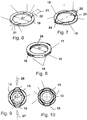
- Figure 6 shows, in a three-dimensional depiction, a front plate 18 of the guide element, which is made of a plastic, for example, is substantially shaped as a circular ring and comprises two thickened regions 21, 22, which lie opposite one another on the ring symmetrically with respect to an axis 23 that is a symmetry axis of the front plate 18.
- the height of the thickened regions 21, 22 can correspond approximately to or be slightly larger than the thickness of the spring element 19.
- Figure 7 shows the front plate 18 depicted in figure 6 comprising a spring element 19 placed thereon, which, in this case, is formed by a closed retaining clip having a diamond shape.
- the diamond shape of the spring element 19 has only two blunt regions 24, 25 which serve to improve grippability in the assembled state.
- the spring clip is retained by the thickened regions 21, 22 and is designed such that it can be compressed exclusively in the direction of the axis 23 and is expandable transversely to the axis 23 and, therefore, radially. To this end, the blunt ends 24, 25 can be gripped using two fingers and moved toward one another in order to expand the spring element 19.
- Figure 8 shows the guide element 15 in the assembled form comprising the first front plate 17 and the second front plate 18.
- the front plates 17, 18 are shaped such that, in the assembled state, they leave space between them for the spring element 19. More particularly, the first front plate 17 can lie on the thickened regions 21, 22.
- Figure 8 shows the spring element 19 between the front plates 17, 18, which protrudes from openings at the outer jacket surface of the guide element and can be manually operated there. As shown at the point 26, the spring element 19 in the unloaded state protrudes into the inner central opening of the guide element.
- the guide element 15 can still be slid onto the annular element 13 by way of said inner opening when the spring element 19 is actuated. Once the sliding-on has been completed, the spring element 19 can be released, thereby permitting it to snap radially inwardly into the groove 14 of the annular element.
- Figure 9 shows, in a perpendicular top view, a section of the guide element 15 comprising an unactuated spring element 19.
- the actuating forces of the spring element are indicated by two arrows 27, 28.
- the annular element 13 is also sketched in the interior thereof, wherein the spring element 19, in the top view, partially penetrates the annular element 13 since it is plunged into the circumferential groove thereof.
- Figure 10 shows, in contrast, the same section as in figure 9 with an actuated spring element 19 that has been expanded by the application of force to the extent that it does not radially touch the circumference of the annular element 13 at any point.
- the guide element 15 comprising the spring element 19 can be slid onto the annular element 13 and can be removed therefrom.
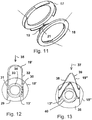
- Figure 11 shows, schematically, the interaction of the front plates 17, 18 before they are assembled to form a guide element.
- a thickened region 21 and the inserted spring element 19 are shown at the front plate 18.
- Figure 12 shows an alternative embodiment of a guide element, an annular element and a spring element.
- the guide element 15' is shown comprising an annular element 13' located concentrically therein.
- the guide element 15' has a wide groove 29 or only two guide channels 30, 31 for the two arms 32, 33 of the spring element 19'.
- the spring element does not have to be expanded to be slid into the groove of the annular element 13', which is depicted by the dashed base 34 having the groove.
- the spring element 19' can be slid easily in the direction of the arrow 35 radially into the guide element 15' in order to plunge into the groove of the annular element and mutually lock the spring and the guide element.
- the guidance of the spring element 19' in the guide element 15' can be designed so tight that the spring element automatically becomes wedged in the guide element.
- the arms 32, 33 of the spring element 19' can also be designed so long that they pass through the guide element and can be secured on the other side by way of a snap ring.
- Figure 13 shows a further embodiment of a guide element and a spring element comprising a guide element 15", which has a groove for receiving the V-shaped spring element 19''.
- the spring element can be clamped in the groove 36 of the guide element 15'' between the groove walls, for example.
- the spring element can be slid in the direction of the arrow 37 into the groove 36 at least to the point at which the arms 38, 39 plunge into the groove of the annular element 13'', which is represented by the dashed base 40 of the groove. Since the spring element 19'' automatically becomes wedged in the groove 36 of the guide element 15", it is also automatically fixed in the locked state.
- Figure 14 shows a guide element 15''' having a recess in which a spring element 41 can be moved radially against a fixed stop 42 of the guide element.
- the spring element 41 can be expanded beyond the outer contour of the annular element 13''' by applying pressure in the radial direction.
- the spring element plunges into the groove of the annular element 13''' to the base 40 thereof.
- the spring 41 protrudes radially from the guide element 15'" on one side for actuation.
- Figure 15 shows the assembly of a securing member comprising, in the following axial order, a cloth ring 43, a suture ring 44 made of titanium and having an external flange, a silicone ring, the inner diameter of which is smaller than that of the remaining components, for forming a sealing lip 8 and a further cloth ring 46.
- the parts can be sutured and/or bonded to one another.
- Figure 16 shows a top view of the suture ring 44 comprising openings 47 in the external flange, which are provided for suturing.
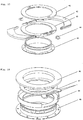
- Figure 17 shows a guide element comprising an upper part 41 and a lower part 43, into which two snap-in spring elements 42 plunge. These spring elements partially penetrate the circumferential groove of the annular element 45 and thereby lock the guide element and the annular element with respect to axial displacement. The spring elements snap into the locked position by way of snap-in hooks. The two snap-in hooks at the spring element are unlocked by applying pressure onto the two pressure pieces, thereby releasing the axial lock and permitting the spring elements to be removed from the groove.
- Figure 18 shows an alternative guide element comprising an upper part 46 and a lower part 48, in which a spiral spring element 47 is accomodated.
- This spring element has recesses at the inner diameter. In the unloaded state, the spring element has a small diameter and plunges into the groove of the annular element 49 to secure it axially and tangentially.
- the inner diameter of the spring element is increased to the extent that the annular element is axially and tangentially displaceable once more with respect to the guide element.
- the implementations of the invention that are shown make it possible to easily and detachably connect a hollow cylindrical component 9 at an opening 2 in tissue of a patient's body, wherein the connection can be easily created even in surgical conditions and is fluid-tight.
- the hollow cylindrical component is easily rotated in the opening, optionally together with further elements secured thereto, such as pumps or valves.
Landscapes
- Health & Medical Sciences (AREA)
- Engineering & Computer Science (AREA)
- Life Sciences & Earth Sciences (AREA)
- Heart & Thoracic Surgery (AREA)
- Surgery (AREA)
- General Health & Medical Sciences (AREA)
- Veterinary Medicine (AREA)
- Biomedical Technology (AREA)
- Public Health (AREA)
- Animal Behavior & Ethology (AREA)
- Medical Informatics (AREA)
- Nuclear Medicine, Radiotherapy & Molecular Imaging (AREA)
- Molecular Biology (AREA)
- General Engineering & Computer Science (AREA)
- Mechanical Engineering (AREA)
- Cardiology (AREA)
- Hematology (AREA)
- Anesthesiology (AREA)
- Physiology (AREA)
- Prostheses (AREA)
- Media Introduction/Drainage Providing Device (AREA)
- Springs (AREA)
Claims (13)
- Système de connexion pour une fixation amovible d'un composant cylindrique creux (9) dans une cavité (2) dans une partie du corps d'un patient, comprenant un élément annulaire (13 ; 13' ; 13" ; 13"') qui a une rainure (14, 36) s'étendant de manière azimutale autour de sa surface de jaquette externe, au moins dans des sections, et comprenant un élément de guidage (15 ; 15' ; 15" ; 15"') qui peut être déplacé, avant la fixation, dans la direction axiale (10) du composant cylindrique creux (9) par rapport à l'élément annulaire, ce par quoi l'élément de guidage (15 ; 15' ; 15") et l'élément annulaire peuvent être glissés l'un dans l'autre au moins partiellement dans la direction axiale, et comprenant un élément de ressort (19 ; 19' ; 19" ; 41) qui est guidé mobile dans l'élément de guidage exclusivement de manière perpendiculaire à la direction axiale (10) de telle manière, pour établir l'état immobile, qu'il plonge au moins partiellement dans la rainure (14, 36) de l'élément annulaire et par conséquent verrouille mutuellement l'élément annulaire et l'élément de guidage dans la direction axiale, où, dans l'état connecté de l'élément annulaire et de l'élément de guidage, un élément est relié au composant cylindrique creux (9) et l'autre élément est mis en place pour une connexion ou un couplage à un bord (3) de la cavité (2) ou au moyen d'un anneau de suture (4), adapté pour être fixé au tissu organique à un bord (3) de la cavité (2) au moyen d'une connexion suturée en utilisant du fil ;
caractérisé en ce que l'élément de ressort (19) est en saillie sur un seul côté au-delà de l'élément de guidage de manière radiale par rapport à la direction axiale (10) et peut être pressé radialement à partir de ce côté dans l'élément de guidage afin de plonger dans la rainure de l'élément annulaire et de verrouiller mutuellement l'élément de ressort et l'élément de guidage, et dans lequel au moins un élément pris parmi l'élément annulaire, l'élément de guidage et l'élément de ressort comprend au moins une matière pris parmi un alliage de titane, de la silicone dure et un polyuréthane. - Système de connexion selon la revendication 1, dans lequel l'élément de ressort (19) est déformable de manière élastique à l'intérieur de l'élément de guidage (15) entre un état verrouillé et un état déverrouillé dans lequel il ne plonge pas dans la rainure (14) de l'élément annulaire (13).
- Système de connexion selon la revendication 2, caractérisé en ce que l'élément de ressort est au moins partiellement en saillie par rapport à l'élément de guidage de sorte qu'une déformation élastique peut être induite manuellement à partir de l'extérieur.
- Système de connexion selon la revendication 4, caractérisé en ce que le guide de l'élément de ressort (19') et l'élément de guidage (15') sont conçus de manière si ajustée que l'élément de ressort se trouve automatiquement coincé dans l'élément de guidage.
- Système de connexion selon la revendication 3 ou la revendication 4, caractérisé en ce que l'élément de ressort a deux bras (32, 33) qui sont si longs qu'ils passent à travers l'élément de guidage pour être fixés sur l'autre côté.
- Système de connexion selon l'une quelconque des revendications précédentes, caractérisé en ce que l'élément de ressort a des bras (38, 39) qui peuvent glisser dans la rainure (36) au moins jusqu'à un point où les bras plongent dans la rainure de l'élément annulaire (13") de l'élément de guidage.
- Système de connexion selon l'une quelconque des revendications précédentes, caractérisé en ce que l'élément de guidage (15"') a une cavité dans laquelle l'élément de ressort (41) peut être déplacé radialement contre une butée (42) fixe de l'élément de guidage.
- Système de connexion selon la revendication 7, caractérisé en ce que l'élément de ressort (41) peut être expansé au-delà d'un contour externe de l'élément annulaire (13"') en appliquant une pression dans une direction radiale.
- Système de connexion selon la revendication 7 ou la revendication 8, caractérisé en ce que, dans un état verrouillé, l'élément de ressort plonge dans la rainure de l'élément annulaire (13"') vers une de ses bases (40) et où le ressort (41) fait saillie radialement à partir de l'élément de guidage (15"') sur un côté pour l'actionnement.
- Système de connexion selon l'une quelconque des revendications précédentes, caractérisé en ce que l'élément de ressort se met en prise dans une position verrouillée au moyen d'un crochet d'encliquetage.
- Système de connexion selon la revendication 10, caractérisé en ce que le crochet d'encliquetage est déverrouillé en appliquant une pression sur une pièce de pression.
- Système de connexion selon la revendication 1 ou l'une des suivantes, caractérisé en ce que l'élément de ressort (19) comprend des composants de résilience élastique à base de matière plastique ou d'un métal, plus particulièrement, étant entièrement fabriqués à base d'un tel matériau résilient et pouvant s'expanser élastiquement de manière radiale par rapport à la direction axiale de l'élément cylindrique.
- Système de connexion selon la revendication 1 ou l'une des suivantes, caractérisé en ce que l'élément (13 ; 13' ; 13" ; 15 ; 15' ; 15"), qui est prévu pour la connexion ou le couplage au bord (3) de la cavité (2), est connecté, ou peut être connecté, à l'anneau de suture (4) qui est connecté directement au bord.
Applications Claiming Priority (4)
| Application Number | Priority Date | Filing Date | Title |
|---|---|---|---|
| US201161486442P | 2011-05-16 | 2011-05-16 | |
| EP11075087A EP2524709A1 (fr) | 2011-05-16 | 2011-05-16 | Système de liaison pour la fixation amovible d'un composant cylindrique creux sur un évidement |
| PCT/EP2012/002150 WO2012156101A1 (fr) | 2011-05-16 | 2012-05-15 | Système de connexion pour la fixation amovible d'un composant cylindrique creux dans une cavité |
| EP12723612.3A EP2709689B1 (fr) | 2011-05-16 | 2012-05-15 | Système de liaison pour la fixation amovible d'un composant cylindrique creux sur un évidement |
Related Parent Applications (1)
| Application Number | Title | Priority Date | Filing Date |
|---|---|---|---|
| EP12723612.3A Division EP2709689B1 (fr) | 2011-05-16 | 2012-05-15 | Système de liaison pour la fixation amovible d'un composant cylindrique creux sur un évidement |
Publications (2)
| Publication Number | Publication Date |
|---|---|
| EP3263149A1 EP3263149A1 (fr) | 2018-01-03 |
| EP3263149B1 true EP3263149B1 (fr) | 2019-11-13 |
Family
ID=44542968
Family Applications (3)
| Application Number | Title | Priority Date | Filing Date |
|---|---|---|---|
| EP11075087A Withdrawn EP2524709A1 (fr) | 2011-05-16 | 2011-05-16 | Système de liaison pour la fixation amovible d'un composant cylindrique creux sur un évidement |
| EP12723612.3A Active EP2709689B1 (fr) | 2011-05-16 | 2012-05-15 | Système de liaison pour la fixation amovible d'un composant cylindrique creux sur un évidement |
| EP17167488.0A Active EP3263149B1 (fr) | 2011-05-16 | 2012-05-15 | Système de liaison pour la fixation amovible d'un composant cylindrique creux sur un évidement |
Family Applications Before (2)
| Application Number | Title | Priority Date | Filing Date |
|---|---|---|---|
| EP11075087A Withdrawn EP2524709A1 (fr) | 2011-05-16 | 2011-05-16 | Système de liaison pour la fixation amovible d'un composant cylindrique creux sur un évidement |
| EP12723612.3A Active EP2709689B1 (fr) | 2011-05-16 | 2012-05-15 | Système de liaison pour la fixation amovible d'un composant cylindrique creux sur un évidement |
Country Status (4)
| Country | Link |
|---|---|
| US (3) | US10779830B2 (fr) |
| EP (3) | EP2524709A1 (fr) |
| CN (2) | CN107049398B (fr) |
| WO (1) | WO2012156101A1 (fr) |
Families Citing this family (30)
| Publication number | Priority date | Publication date | Assignee | Title |
|---|---|---|---|---|
| EP3141269A1 (fr) | 2015-09-11 | 2017-03-15 | Berlin Heart GmbH | Systeme destine a relier une pompe a sang a un coeur |
| EP3173107A1 (fr) | 2015-11-25 | 2017-05-31 | Berlin Heart GmbH | Dispositif de connexion |
| US9968720B2 (en) | 2016-04-11 | 2018-05-15 | CorWave SA | Implantable pump system having an undulating membrane |
| US10166319B2 (en) | 2016-04-11 | 2019-01-01 | CorWave SA | Implantable pump system having a coaxial ventricular cannula |
| DE102016209871A1 (de) | 2016-06-06 | 2017-12-07 | Robert Bosch Gmbh | Stanzvorrichtung und Verfahren zum Stanzen eines Lumens und Implantieren einer Implantateinrichtung |
| EP3515525B1 (fr) * | 2016-09-19 | 2023-11-29 | Evaheart, Inc. | Canule cardiaque |
| WO2018178939A1 (fr) | 2017-03-31 | 2018-10-04 | CorWave SA | Système de pompe implantable munie d'une membrane rectangulaire |
| FR3073578B1 (fr) | 2017-11-10 | 2019-12-13 | Corwave | Circulateur de fluide a membrane ondulante |
| DE102017220777A1 (de) * | 2017-11-21 | 2019-05-23 | Robert Bosch Gmbh | Kabel mit Dichtung für ein Implantat |
| US10188779B1 (en) | 2017-11-29 | 2019-01-29 | CorWave SA | Implantable pump system having an undulating membrane with improved hydraulic performance |
| DE102018201030B4 (de) | 2018-01-24 | 2025-10-16 | Kardion Gmbh | Magnetkuppelelement mit magnetischer Lagerungsfunktion |
| DE102018206750A1 (de) | 2018-05-02 | 2019-11-07 | Kardion Gmbh | Vorrichtung zur induktiven Energieübertragung in einen menschlichen Körper und deren Verwendung |
| DE102018206754A1 (de) | 2018-05-02 | 2019-11-07 | Kardion Gmbh | Verfahren und Vorrichtung zur Bestimmung der Temperatur an einer Oberfläche sowie Verwendung des Verfahrens |
| DE102018206724A1 (de) | 2018-05-02 | 2019-11-07 | Kardion Gmbh | Energieübertragungssystem und Verfahren zur drahtlosen Energieübertragung |
| DE102018206725A1 (de) | 2018-05-02 | 2019-11-07 | Kardion Gmbh | Empfangseinheit, Sendeeinheit, Energieübertragungssystem und Verfahren zur drahtlosen Energieübertragung |
| DE102018206731A1 (de) | 2018-05-02 | 2019-11-07 | Kardion Gmbh | Vorrichtung zur induktiven Energieübertragung in einen menschlichen Körper und Verwendung der Vorrichtung |
| DE102018206727A1 (de) | 2018-05-02 | 2019-11-07 | Kardion Gmbh | Energieübertragungssystem und Empfangseinheit zur drahtlosen transkutanen Energieübertragung |
| DE102018208555A1 (de) | 2018-05-30 | 2019-12-05 | Kardion Gmbh | Vorrichtung zum Verankern eines Herzunterstützungssystems in einem Blutgefäß, Verfahren zum Betreiben und Herstellverfahren zum Herstellen einer Vorrichtung und Herzunterstützungssystem |
| US12551689B2 (en) | 2018-12-05 | 2026-02-17 | CorWave SA | Apparatus and methods for coupling a blood pump to the heart |
| EP3938006B1 (fr) | 2019-03-15 | 2025-01-15 | CorWave SA | Systèmes de commande d'une pompe implantable à sang |
| JP3231722U (ja) * | 2019-11-07 | 2021-04-22 | ジョン・トーマス・ワンガーシン | 第2の窪み部と開口孔まわりの環状隆起部とを備えたケース |
| FR3103101A1 (fr) * | 2019-11-15 | 2021-05-21 | Fineheart | Dispositif d’ancrage d’une pompe cardiaque et ensemble de pose d’une pompe cardiaque équipé d’un tel dispositif d’ancrage |
| US11191946B2 (en) | 2020-03-06 | 2021-12-07 | CorWave SA | Implantable blood pumps comprising a linear bearing |
| US11699551B2 (en) | 2020-11-05 | 2023-07-11 | Kardion Gmbh | Device for inductive energy transmission in a human body and use of the device |
| JP2025515482A (ja) | 2022-04-26 | 2025-05-15 | コルウェーブ エスアー | カプセル化されたアクチュエーターを有する血液ポンプ |
| US20230414070A1 (en) * | 2022-06-22 | 2023-12-28 | Karl Storz Endovision, Inc. | Tensioning Device and Endoscope Assembled Therewith |
| CN120282816A (zh) | 2022-11-15 | 2025-07-08 | 科瓦韦公司 | 包含改进的心尖部连接器及/或移植物连接器的可植入心脏泵系统 |
| US12257427B2 (en) | 2022-11-15 | 2025-03-25 | CorWave SA | Implantable heart pump systems including an improved apical connector and/or graft connector |
| CN117482383B (zh) * | 2024-01-02 | 2024-03-22 | 苏州同心医疗科技股份有限公司 | 心室连接装置 |
| CN117899352B (zh) * | 2024-03-20 | 2024-07-05 | 苏州同心医疗科技股份有限公司 | 心室连接装置及心室连接系统 |
Family Cites Families (21)
| Publication number | Priority date | Publication date | Assignee | Title |
|---|---|---|---|---|
| US3527485A (en) * | 1968-07-26 | 1970-09-08 | Btr Industries Ltd | Releasable pipe coupling |
| US3919722A (en) * | 1973-03-06 | 1975-11-18 | Us Health | Totally implantable artificial replacement heart |
| US4423892A (en) * | 1980-10-29 | 1984-01-03 | Bartholomew Donald D | Swivelable quick connector assembly |
| US4591192A (en) * | 1984-03-15 | 1986-05-27 | Rain Bird Consumer Products Mfg. Corp. | Quick connect coupling |
| US5089014A (en) * | 1987-05-18 | 1992-02-18 | Holfert John W | Tubular interconnect device for use within the circulatory system |
| US5314469A (en) * | 1992-03-11 | 1994-05-24 | Milwaukee Heart Research Foundation | Artificial heart |
| DE4300037C1 (de) * | 1993-01-02 | 1994-04-21 | Raymond A & Cie | Lösbare Steckverbindung |
| US6001056A (en) * | 1998-11-13 | 1999-12-14 | Baxter International Inc. | Smooth ventricular assist device conduit |
| US6319231B1 (en) * | 1999-02-12 | 2001-11-20 | Abiomed, Inc. | Medical connector |
| US6146325A (en) * | 1999-06-03 | 2000-11-14 | Arrow International, Inc. | Ventricular assist device |
| US6346071B1 (en) * | 1999-07-16 | 2002-02-12 | World Heart Corporation | Inflow conduit assembly for a ventricular assist device |
| US20020095210A1 (en) * | 2001-01-16 | 2002-07-18 | Finnegan Michael T. | Heart pump graft connector and system |
| WO2003001980A2 (fr) * | 2001-06-29 | 2003-01-09 | Medquest Products,Inc. | Procede et appareil de canulation |
| WO2004101161A1 (fr) | 2003-05-16 | 2004-11-25 | Haimo Technologies Inc. | Separateur centrifuge gaz-liquide reglable et procede de separation |
| US7172550B2 (en) * | 2003-07-31 | 2007-02-06 | Terumo Corporation | Adjustable coupling mechanism for the conduit on a ventricular assist device |
| US9744279B2 (en) | 2005-12-08 | 2017-08-29 | Heartware, Inc. | Implant connector |
| US10368899B2 (en) | 2006-01-13 | 2019-08-06 | Heartware, Inc. | Surgical tool for coring precise holes and providing for retrieval of tissue |
| US20070167969A1 (en) | 2006-01-13 | 2007-07-19 | Rajesh Pandey | Surgical cutting tool for making precise and accurate incisions |
| GB2440912B (en) | 2006-08-14 | 2009-03-04 | Heartvalve Ltd | Surgical fastening device |
| US9682180B2 (en) * | 2009-11-15 | 2017-06-20 | Thoratec Corporation | Attachment system, device and method |
| EP2995327A1 (fr) * | 2011-03-02 | 2016-03-16 | Thoratec Corporation | Manchon ventriculaire |
-
2011
- 2011-05-16 EP EP11075087A patent/EP2524709A1/fr not_active Withdrawn
-
2012
- 2012-05-15 US US14/117,428 patent/US10779830B2/en active Active
- 2012-05-15 CN CN201710088924.5A patent/CN107049398B/zh not_active Expired - Fee Related
- 2012-05-15 WO PCT/EP2012/002150 patent/WO2012156101A1/fr not_active Ceased
- 2012-05-15 EP EP12723612.3A patent/EP2709689B1/fr active Active
- 2012-05-15 CN CN201280023866.3A patent/CN103608050B/zh active Active
- 2012-05-15 EP EP17167488.0A patent/EP3263149B1/fr active Active
-
2020
- 2020-07-27 US US16/940,132 patent/US20200352573A1/en not_active Abandoned
-
2023
- 2023-11-16 US US18/511,276 patent/US20240081828A1/en not_active Abandoned
Non-Patent Citations (1)
| Title |
|---|
| None * |
Also Published As
| Publication number | Publication date |
|---|---|
| US20200352573A1 (en) | 2020-11-12 |
| EP2524709A1 (fr) | 2012-11-21 |
| US20240081828A1 (en) | 2024-03-14 |
| EP2709689B1 (fr) | 2017-04-26 |
| US10779830B2 (en) | 2020-09-22 |
| EP2709689A1 (fr) | 2014-03-26 |
| US20140316426A1 (en) | 2014-10-23 |
| CN103608050A (zh) | 2014-02-26 |
| CN103608050B (zh) | 2017-03-15 |
| EP3263149A1 (fr) | 2018-01-03 |
| CN107049398B (zh) | 2020-07-10 |
| CN107049398A (zh) | 2017-08-18 |
| WO2012156101A1 (fr) | 2012-11-22 |
Similar Documents
| Publication | Publication Date | Title |
|---|---|---|
| US20240081828A1 (en) | Connection system for the detachable fixation of a hollow cylindrical component at a recess | |
| US7303553B2 (en) | Device for connecting a cannula made of a flexible material with a tube | |
| CN104902827B (zh) | 内窥镜处理器具 | |
| CN102395402B (zh) | 卫生保持器 | |
| CN115282461B (zh) | 带有阀的针组件以及留置针组件 | |
| JP6792328B2 (ja) | ローディングユニット係止カラー | |
| US6319231B1 (en) | Medical connector | |
| KR102534555B1 (ko) | 고정부를 갖는 단일 동작의 푸시 연결식 도관 피팅 | |
| CN104869917A (zh) | 内窥镜处理器具 | |
| CN112969418B (zh) | 夹具单元及内窥镜夹具 | |
| EP3644876A1 (fr) | Dispositifs de fixation de canule et procédés destinés à un système robotique chirurgical | |
| GB1582914A (en) | Coupling device for conduits | |
| US9744286B2 (en) | Connection system for creating a connection channel for bodily fluids | |
| WO2013115022A1 (fr) | Dispositif d'anastomose vasculaire et procédé d'anastomose vasculaire | |
| CN101155552A (zh) | 一种端对侧吻合装置 | |
| WO2014149892A1 (fr) | Manchon ventriculaire | |
| US20250345591A1 (en) | Ventricular Cuff | |
| CN112451005A (zh) | 插管固定装置、系统和相关方法 | |
| JP2009112769A (ja) | 整形外科用治具、ピン、および方法 | |
| CN110772303B (zh) | 一种穿刺器外壳及穿刺器 | |
| US20250302661A1 (en) | An ostomy appliance and a coupling therefore | |
| US20240058044A1 (en) | Systems and methods for securely attaching an anchor to an implant body | |
| EP3685776A1 (fr) | Systèmes de support pour instruments médicaux | |
| JP2011530684A (ja) | 耐振継手アッセンブリ |
Legal Events
| Date | Code | Title | Description |
|---|---|---|---|
| PUAI | Public reference made under article 153(3) epc to a published international application that has entered the european phase |
Free format text: ORIGINAL CODE: 0009012 |
|
| STAA | Information on the status of an ep patent application or granted ep patent |
Free format text: STATUS: THE APPLICATION HAS BEEN PUBLISHED |
|
| AC | Divisional application: reference to earlier application |
Ref document number: 2709689 Country of ref document: EP Kind code of ref document: P |
|
| AK | Designated contracting states |
Kind code of ref document: A1 Designated state(s): AL AT BE BG CH CY CZ DE DK EE ES FI FR GB GR HR HU IE IS IT LI LT LU LV MC MK MT NL NO PL PT RO RS SE SI SK SM TR |
|
| RIN1 | Information on inventor provided before grant (corrected) |
Inventor name: GOELLNER, MANFRED Inventor name: MARCINOWSKI, DANIEL |
|
| STAA | Information on the status of an ep patent application or granted ep patent |
Free format text: STATUS: REQUEST FOR EXAMINATION WAS MADE |
|
| 17P | Request for examination filed |
Effective date: 20180509 |
|
| RBV | Designated contracting states (corrected) |
Designated state(s): AL AT BE BG CH CY CZ DE DK EE ES FI FR GB GR HR HU IE IS IT LI LT LU LV MC MK MT NL NO PL PT RO RS SE SI SK SM TR |
|
| GRAP | Despatch of communication of intention to grant a patent |
Free format text: ORIGINAL CODE: EPIDOSNIGR1 |
|
| STAA | Information on the status of an ep patent application or granted ep patent |
Free format text: STATUS: GRANT OF PATENT IS INTENDED |
|
| INTG | Intention to grant announced |
Effective date: 20181210 |
|
| GRAJ | Information related to disapproval of communication of intention to grant by the applicant or resumption of examination proceedings by the epo deleted |
Free format text: ORIGINAL CODE: EPIDOSDIGR1 |
|
| STAA | Information on the status of an ep patent application or granted ep patent |
Free format text: STATUS: REQUEST FOR EXAMINATION WAS MADE |
|
| INTC | Intention to grant announced (deleted) | ||
| GRAP | Despatch of communication of intention to grant a patent |
Free format text: ORIGINAL CODE: EPIDOSNIGR1 |
|
| STAA | Information on the status of an ep patent application or granted ep patent |
Free format text: STATUS: GRANT OF PATENT IS INTENDED |
|
| INTG | Intention to grant announced |
Effective date: 20190603 |
|
| GRAS | Grant fee paid |
Free format text: ORIGINAL CODE: EPIDOSNIGR3 |
|
| GRAA | (expected) grant |
Free format text: ORIGINAL CODE: 0009210 |
|
| STAA | Information on the status of an ep patent application or granted ep patent |
Free format text: STATUS: THE PATENT HAS BEEN GRANTED |
|
| AC | Divisional application: reference to earlier application |
Ref document number: 2709689 Country of ref document: EP Kind code of ref document: P |
|
| AK | Designated contracting states |
Kind code of ref document: B1 Designated state(s): AL AT BE BG CH CY CZ DE DK EE ES FI FR GB GR HR HU IE IS IT LI LT LU LV MC MK MT NL NO PL PT RO RS SE SI SK SM TR |
|
| REG | Reference to a national code |
Ref country code: CH Ref legal event code: EP Ref country code: AT Ref legal event code: REF Ref document number: 1201007 Country of ref document: AT Kind code of ref document: T Effective date: 20191115 |
|
| REG | Reference to a national code |
Ref country code: DE Ref legal event code: R096 Ref document number: 602012065752 Country of ref document: DE |
|
| REG | Reference to a national code |
Ref country code: IE Ref legal event code: FG4D |
|
| REG | Reference to a national code |
Ref country code: NL Ref legal event code: MP Effective date: 20191113 |
|
| REG | Reference to a national code |
Ref country code: LT Ref legal event code: MG4D |
|
| PG25 | Lapsed in a contracting state [announced via postgrant information from national office to epo] |
Ref country code: FI Free format text: LAPSE BECAUSE OF FAILURE TO SUBMIT A TRANSLATION OF THE DESCRIPTION OR TO PAY THE FEE WITHIN THE PRESCRIBED TIME-LIMIT Effective date: 20191113 Ref country code: BG Free format text: LAPSE BECAUSE OF FAILURE TO SUBMIT A TRANSLATION OF THE DESCRIPTION OR TO PAY THE FEE WITHIN THE PRESCRIBED TIME-LIMIT Effective date: 20200213 Ref country code: NO Free format text: LAPSE BECAUSE OF FAILURE TO SUBMIT A TRANSLATION OF THE DESCRIPTION OR TO PAY THE FEE WITHIN THE PRESCRIBED TIME-LIMIT Effective date: 20200213 Ref country code: LT Free format text: LAPSE BECAUSE OF FAILURE TO SUBMIT A TRANSLATION OF THE DESCRIPTION OR TO PAY THE FEE WITHIN THE PRESCRIBED TIME-LIMIT Effective date: 20191113 Ref country code: PT Free format text: LAPSE BECAUSE OF FAILURE TO SUBMIT A TRANSLATION OF THE DESCRIPTION OR TO PAY THE FEE WITHIN THE PRESCRIBED TIME-LIMIT Effective date: 20200313 Ref country code: GR Free format text: LAPSE BECAUSE OF FAILURE TO SUBMIT A TRANSLATION OF THE DESCRIPTION OR TO PAY THE FEE WITHIN THE PRESCRIBED TIME-LIMIT Effective date: 20200214 Ref country code: PL Free format text: LAPSE BECAUSE OF FAILURE TO SUBMIT A TRANSLATION OF THE DESCRIPTION OR TO PAY THE FEE WITHIN THE PRESCRIBED TIME-LIMIT Effective date: 20191113 Ref country code: LV Free format text: LAPSE BECAUSE OF FAILURE TO SUBMIT A TRANSLATION OF THE DESCRIPTION OR TO PAY THE FEE WITHIN THE PRESCRIBED TIME-LIMIT Effective date: 20191113 Ref country code: NL Free format text: LAPSE BECAUSE OF FAILURE TO SUBMIT A TRANSLATION OF THE DESCRIPTION OR TO PAY THE FEE WITHIN THE PRESCRIBED TIME-LIMIT Effective date: 20191113 Ref country code: SE Free format text: LAPSE BECAUSE OF FAILURE TO SUBMIT A TRANSLATION OF THE DESCRIPTION OR TO PAY THE FEE WITHIN THE PRESCRIBED TIME-LIMIT Effective date: 20191113 |
|
| PG25 | Lapsed in a contracting state [announced via postgrant information from national office to epo] |
Ref country code: RS Free format text: LAPSE BECAUSE OF FAILURE TO SUBMIT A TRANSLATION OF THE DESCRIPTION OR TO PAY THE FEE WITHIN THE PRESCRIBED TIME-LIMIT Effective date: 20191113 Ref country code: HR Free format text: LAPSE BECAUSE OF FAILURE TO SUBMIT A TRANSLATION OF THE DESCRIPTION OR TO PAY THE FEE WITHIN THE PRESCRIBED TIME-LIMIT Effective date: 20191113 Ref country code: IS Free format text: LAPSE BECAUSE OF FAILURE TO SUBMIT A TRANSLATION OF THE DESCRIPTION OR TO PAY THE FEE WITHIN THE PRESCRIBED TIME-LIMIT Effective date: 20200313 |
|
| PG25 | Lapsed in a contracting state [announced via postgrant information from national office to epo] |
Ref country code: AL Free format text: LAPSE BECAUSE OF FAILURE TO SUBMIT A TRANSLATION OF THE DESCRIPTION OR TO PAY THE FEE WITHIN THE PRESCRIBED TIME-LIMIT Effective date: 20191113 |
|
| PG25 | Lapsed in a contracting state [announced via postgrant information from national office to epo] |
Ref country code: DK Free format text: LAPSE BECAUSE OF FAILURE TO SUBMIT A TRANSLATION OF THE DESCRIPTION OR TO PAY THE FEE WITHIN THE PRESCRIBED TIME-LIMIT Effective date: 20191113 Ref country code: EE Free format text: LAPSE BECAUSE OF FAILURE TO SUBMIT A TRANSLATION OF THE DESCRIPTION OR TO PAY THE FEE WITHIN THE PRESCRIBED TIME-LIMIT Effective date: 20191113 Ref country code: CZ Free format text: LAPSE BECAUSE OF FAILURE TO SUBMIT A TRANSLATION OF THE DESCRIPTION OR TO PAY THE FEE WITHIN THE PRESCRIBED TIME-LIMIT Effective date: 20191113 Ref country code: RO Free format text: LAPSE BECAUSE OF FAILURE TO SUBMIT A TRANSLATION OF THE DESCRIPTION OR TO PAY THE FEE WITHIN THE PRESCRIBED TIME-LIMIT Effective date: 20191113 Ref country code: ES Free format text: LAPSE BECAUSE OF FAILURE TO SUBMIT A TRANSLATION OF THE DESCRIPTION OR TO PAY THE FEE WITHIN THE PRESCRIBED TIME-LIMIT Effective date: 20191113 |
|
| REG | Reference to a national code |
Ref country code: DE Ref legal event code: R097 Ref document number: 602012065752 Country of ref document: DE |
|
| REG | Reference to a national code |
Ref country code: AT Ref legal event code: MK05 Ref document number: 1201007 Country of ref document: AT Kind code of ref document: T Effective date: 20191113 |
|
| PG25 | Lapsed in a contracting state [announced via postgrant information from national office to epo] |
Ref country code: SM Free format text: LAPSE BECAUSE OF FAILURE TO SUBMIT A TRANSLATION OF THE DESCRIPTION OR TO PAY THE FEE WITHIN THE PRESCRIBED TIME-LIMIT Effective date: 20191113 Ref country code: SK Free format text: LAPSE BECAUSE OF FAILURE TO SUBMIT A TRANSLATION OF THE DESCRIPTION OR TO PAY THE FEE WITHIN THE PRESCRIBED TIME-LIMIT Effective date: 20191113 |
|
| PLBE | No opposition filed within time limit |
Free format text: ORIGINAL CODE: 0009261 |
|
| STAA | Information on the status of an ep patent application or granted ep patent |
Free format text: STATUS: NO OPPOSITION FILED WITHIN TIME LIMIT |
|
| 26N | No opposition filed |
Effective date: 20200814 |
|
| REG | Reference to a national code |
Ref country code: DE Ref legal event code: R079 Ref document number: 602012065752 Country of ref document: DE Free format text: PREVIOUS MAIN CLASS: A61M0001100000 Ipc: A61M0060000000 |
|
| PG25 | Lapsed in a contracting state [announced via postgrant information from national office to epo] |
Ref country code: SI Free format text: LAPSE BECAUSE OF FAILURE TO SUBMIT A TRANSLATION OF THE DESCRIPTION OR TO PAY THE FEE WITHIN THE PRESCRIBED TIME-LIMIT Effective date: 20191113 Ref country code: AT Free format text: LAPSE BECAUSE OF FAILURE TO SUBMIT A TRANSLATION OF THE DESCRIPTION OR TO PAY THE FEE WITHIN THE PRESCRIBED TIME-LIMIT Effective date: 20191113 |
|
| PG25 | Lapsed in a contracting state [announced via postgrant information from national office to epo] |
Ref country code: MC Free format text: LAPSE BECAUSE OF FAILURE TO SUBMIT A TRANSLATION OF THE DESCRIPTION OR TO PAY THE FEE WITHIN THE PRESCRIBED TIME-LIMIT Effective date: 20191113 Ref country code: LI Free format text: LAPSE BECAUSE OF NON-PAYMENT OF DUE FEES Effective date: 20200531 Ref country code: IT Free format text: LAPSE BECAUSE OF FAILURE TO SUBMIT A TRANSLATION OF THE DESCRIPTION OR TO PAY THE FEE WITHIN THE PRESCRIBED TIME-LIMIT Effective date: 20191113 Ref country code: CH Free format text: LAPSE BECAUSE OF NON-PAYMENT OF DUE FEES Effective date: 20200531 |
|
| REG | Reference to a national code |
Ref country code: BE Ref legal event code: MM Effective date: 20200531 |
|
| GBPC | Gb: european patent ceased through non-payment of renewal fee |
Effective date: 20200515 |
|
| PG25 | Lapsed in a contracting state [announced via postgrant information from national office to epo] |
Ref country code: LU Free format text: LAPSE BECAUSE OF NON-PAYMENT OF DUE FEES Effective date: 20200515 |
|
| PG25 | Lapsed in a contracting state [announced via postgrant information from national office to epo] |
Ref country code: GB Free format text: LAPSE BECAUSE OF NON-PAYMENT OF DUE FEES Effective date: 20200515 Ref country code: IE Free format text: LAPSE BECAUSE OF NON-PAYMENT OF DUE FEES Effective date: 20200515 Ref country code: FR Free format text: LAPSE BECAUSE OF NON-PAYMENT OF DUE FEES Effective date: 20200531 |
|
| PG25 | Lapsed in a contracting state [announced via postgrant information from national office to epo] |
Ref country code: BE Free format text: LAPSE BECAUSE OF NON-PAYMENT OF DUE FEES Effective date: 20200531 |
|
| PG25 | Lapsed in a contracting state [announced via postgrant information from national office to epo] |
Ref country code: TR Free format text: LAPSE BECAUSE OF FAILURE TO SUBMIT A TRANSLATION OF THE DESCRIPTION OR TO PAY THE FEE WITHIN THE PRESCRIBED TIME-LIMIT Effective date: 20191113 Ref country code: MT Free format text: LAPSE BECAUSE OF FAILURE TO SUBMIT A TRANSLATION OF THE DESCRIPTION OR TO PAY THE FEE WITHIN THE PRESCRIBED TIME-LIMIT Effective date: 20191113 Ref country code: CY Free format text: LAPSE BECAUSE OF FAILURE TO SUBMIT A TRANSLATION OF THE DESCRIPTION OR TO PAY THE FEE WITHIN THE PRESCRIBED TIME-LIMIT Effective date: 20191113 |
|
| PG25 | Lapsed in a contracting state [announced via postgrant information from national office to epo] |
Ref country code: MK Free format text: LAPSE BECAUSE OF FAILURE TO SUBMIT A TRANSLATION OF THE DESCRIPTION OR TO PAY THE FEE WITHIN THE PRESCRIBED TIME-LIMIT Effective date: 20191113 |
|
| P01 | Opt-out of the competence of the unified patent court (upc) registered |
Effective date: 20230626 |
|
| PGFP | Annual fee paid to national office [announced via postgrant information from national office to epo] |
Ref country code: DE Payment date: 20250530 Year of fee payment: 14 |