EP3263164A1 - Beatmungsgerät zur apap-beatmung mit oszillatorischem druck - Google Patents
Beatmungsgerät zur apap-beatmung mit oszillatorischem druck Download PDFInfo
- Publication number
- EP3263164A1 EP3263164A1 EP17001014.4A EP17001014A EP3263164A1 EP 3263164 A1 EP3263164 A1 EP 3263164A1 EP 17001014 A EP17001014 A EP 17001014A EP 3263164 A1 EP3263164 A1 EP 3263164A1
- Authority
- EP
- European Patent Office
- Prior art keywords
- pressure
- autocpap
- controller
- flow
- fan
- Prior art date
- Legal status (The legal status is an assumption and is not a legal conclusion. Google has not performed a legal analysis and makes no representation as to the accuracy of the status listed.)
- Granted
Links
Images


Classifications
-
- A—HUMAN NECESSITIES
- A61—MEDICAL OR VETERINARY SCIENCE; HYGIENE
- A61M—DEVICES FOR INTRODUCING MEDIA INTO, OR ONTO, THE BODY; DEVICES FOR TRANSDUCING BODY MEDIA OR FOR TAKING MEDIA FROM THE BODY; DEVICES FOR PRODUCING OR ENDING SLEEP OR STUPOR
- A61M16/00—Devices for influencing the respiratory system of patients by gas treatment, e.g. ventilators; Tracheal tubes
- A61M16/0003—Accessories therefor, e.g. sensors, vibrators, negative pressure
- A61M16/0006—Accessories therefor, e.g. sensors, vibrators, negative pressure with means for creating vibrations in patients' airways
-
- A—HUMAN NECESSITIES
- A61—MEDICAL OR VETERINARY SCIENCE; HYGIENE
- A61M—DEVICES FOR INTRODUCING MEDIA INTO, OR ONTO, THE BODY; DEVICES FOR TRANSDUCING BODY MEDIA OR FOR TAKING MEDIA FROM THE BODY; DEVICES FOR PRODUCING OR ENDING SLEEP OR STUPOR
- A61M16/00—Devices for influencing the respiratory system of patients by gas treatment, e.g. ventilators; Tracheal tubes
- A61M16/0003—Accessories therefor, e.g. sensors, vibrators, negative pressure
-
- A—HUMAN NECESSITIES
- A61—MEDICAL OR VETERINARY SCIENCE; HYGIENE
- A61B—DIAGNOSIS; SURGERY; IDENTIFICATION
- A61B5/00—Measuring for diagnostic purposes; Identification of persons
- A61B5/08—Measuring devices for evaluating the respiratory organs
- A61B5/0826—Detecting or evaluating apnoea events
-
- A—HUMAN NECESSITIES
- A61—MEDICAL OR VETERINARY SCIENCE; HYGIENE
- A61B—DIAGNOSIS; SURGERY; IDENTIFICATION
- A61B5/00—Measuring for diagnostic purposes; Identification of persons
- A61B5/08—Measuring devices for evaluating the respiratory organs
- A61B5/087—Measuring breath flow
- A61B5/09—Measuring breath flow using an element rotated by the flow
-
- A—HUMAN NECESSITIES
- A61—MEDICAL OR VETERINARY SCIENCE; HYGIENE
- A61M—DEVICES FOR INTRODUCING MEDIA INTO, OR ONTO, THE BODY; DEVICES FOR TRANSDUCING BODY MEDIA OR FOR TAKING MEDIA FROM THE BODY; DEVICES FOR PRODUCING OR ENDING SLEEP OR STUPOR
- A61M16/00—Devices for influencing the respiratory system of patients by gas treatment, e.g. ventilators; Tracheal tubes
- A61M16/0051—Devices for influencing the respiratory system of patients by gas treatment, e.g. ventilators; Tracheal tubes with alarm devices
-
- A—HUMAN NECESSITIES
- A61—MEDICAL OR VETERINARY SCIENCE; HYGIENE
- A61M—DEVICES FOR INTRODUCING MEDIA INTO, OR ONTO, THE BODY; DEVICES FOR TRANSDUCING BODY MEDIA OR FOR TAKING MEDIA FROM THE BODY; DEVICES FOR PRODUCING OR ENDING SLEEP OR STUPOR
- A61M16/00—Devices for influencing the respiratory system of patients by gas treatment, e.g. ventilators; Tracheal tubes
- A61M16/0057—Pumps therefor
- A61M16/0066—Blowers or centrifugal pumps
-
- A—HUMAN NECESSITIES
- A61—MEDICAL OR VETERINARY SCIENCE; HYGIENE
- A61M—DEVICES FOR INTRODUCING MEDIA INTO, OR ONTO, THE BODY; DEVICES FOR TRANSDUCING BODY MEDIA OR FOR TAKING MEDIA FROM THE BODY; DEVICES FOR PRODUCING OR ENDING SLEEP OR STUPOR
- A61M16/00—Devices for influencing the respiratory system of patients by gas treatment, e.g. ventilators; Tracheal tubes
- A61M16/0057—Pumps therefor
- A61M16/0066—Blowers or centrifugal pumps
- A61M16/0069—Blowers or centrifugal pumps the speed thereof being controlled by respiratory parameters, e.g. by inhalation
-
- A—HUMAN NECESSITIES
- A61—MEDICAL OR VETERINARY SCIENCE; HYGIENE
- A61M—DEVICES FOR INTRODUCING MEDIA INTO, OR ONTO, THE BODY; DEVICES FOR TRANSDUCING BODY MEDIA OR FOR TAKING MEDIA FROM THE BODY; DEVICES FOR PRODUCING OR ENDING SLEEP OR STUPOR
- A61M16/00—Devices for influencing the respiratory system of patients by gas treatment, e.g. ventilators; Tracheal tubes
- A61M16/021—Devices for influencing the respiratory system of patients by gas treatment, e.g. ventilators; Tracheal tubes operated by electrical means
- A61M16/022—Control means therefor
- A61M16/024—Control means therefor including calculation means, e.g. using a processor
-
- A—HUMAN NECESSITIES
- A61—MEDICAL OR VETERINARY SCIENCE; HYGIENE
- A61M—DEVICES FOR INTRODUCING MEDIA INTO, OR ONTO, THE BODY; DEVICES FOR TRANSDUCING BODY MEDIA OR FOR TAKING MEDIA FROM THE BODY; DEVICES FOR PRODUCING OR ENDING SLEEP OR STUPOR
- A61M16/00—Devices for influencing the respiratory system of patients by gas treatment, e.g. ventilators; Tracheal tubes
- A61M16/10—Preparation of respiratory gases or vapours
- A61M16/14—Preparation of respiratory gases or vapours by mixing different fluids, one of them being in a liquid phase
- A61M16/16—Devices to humidify the respiration air
- A61M16/161—Devices to humidify the respiration air with means for measuring the humidity
-
- A—HUMAN NECESSITIES
- A61—MEDICAL OR VETERINARY SCIENCE; HYGIENE
- A61B—DIAGNOSIS; SURGERY; IDENTIFICATION
- A61B2560/00—Constructional details of operational features of apparatus; Accessories for medical measuring apparatus
- A61B2560/02—Operational features
- A61B2560/0242—Operational features adapted to measure environmental factors, e.g. temperature, pollution
- A61B2560/0247—Operational features adapted to measure environmental factors, e.g. temperature, pollution for compensation or correction of the measured physiological value
-
- A—HUMAN NECESSITIES
- A61—MEDICAL OR VETERINARY SCIENCE; HYGIENE
- A61B—DIAGNOSIS; SURGERY; IDENTIFICATION
- A61B2560/00—Constructional details of operational features of apparatus; Accessories for medical measuring apparatus
- A61B2560/02—Operational features
- A61B2560/0242—Operational features adapted to measure environmental factors, e.g. temperature, pollution
- A61B2560/0247—Operational features adapted to measure environmental factors, e.g. temperature, pollution for compensation or correction of the measured physiological value
- A61B2560/0257—Operational features adapted to measure environmental factors, e.g. temperature, pollution for compensation or correction of the measured physiological value using atmospheric pressure
-
- A—HUMAN NECESSITIES
- A61—MEDICAL OR VETERINARY SCIENCE; HYGIENE
- A61M—DEVICES FOR INTRODUCING MEDIA INTO, OR ONTO, THE BODY; DEVICES FOR TRANSDUCING BODY MEDIA OR FOR TAKING MEDIA FROM THE BODY; DEVICES FOR PRODUCING OR ENDING SLEEP OR STUPOR
- A61M16/00—Devices for influencing the respiratory system of patients by gas treatment, e.g. ventilators; Tracheal tubes
- A61M16/10—Preparation of respiratory gases or vapours
- A61M16/105—Filters
- A61M16/1055—Filters bacterial
-
- A—HUMAN NECESSITIES
- A61—MEDICAL OR VETERINARY SCIENCE; HYGIENE
- A61M—DEVICES FOR INTRODUCING MEDIA INTO, OR ONTO, THE BODY; DEVICES FOR TRANSDUCING BODY MEDIA OR FOR TAKING MEDIA FROM THE BODY; DEVICES FOR PRODUCING OR ENDING SLEEP OR STUPOR
- A61M16/00—Devices for influencing the respiratory system of patients by gas treatment, e.g. ventilators; Tracheal tubes
- A61M16/0003—Accessories therefor, e.g. sensors, vibrators, negative pressure
- A61M2016/0027—Accessories therefor, e.g. sensors, vibrators, negative pressure pressure meter
-
- A—HUMAN NECESSITIES
- A61—MEDICAL OR VETERINARY SCIENCE; HYGIENE
- A61M—DEVICES FOR INTRODUCING MEDIA INTO, OR ONTO, THE BODY; DEVICES FOR TRANSDUCING BODY MEDIA OR FOR TAKING MEDIA FROM THE BODY; DEVICES FOR PRODUCING OR ENDING SLEEP OR STUPOR
- A61M16/00—Devices for influencing the respiratory system of patients by gas treatment, e.g. ventilators; Tracheal tubes
- A61M16/0003—Accessories therefor, e.g. sensors, vibrators, negative pressure
- A61M2016/003—Accessories therefor, e.g. sensors, vibrators, negative pressure with a flowmeter
-
- A—HUMAN NECESSITIES
- A61—MEDICAL OR VETERINARY SCIENCE; HYGIENE
- A61M—DEVICES FOR INTRODUCING MEDIA INTO, OR ONTO, THE BODY; DEVICES FOR TRANSDUCING BODY MEDIA OR FOR TAKING MEDIA FROM THE BODY; DEVICES FOR PRODUCING OR ENDING SLEEP OR STUPOR
- A61M16/00—Devices for influencing the respiratory system of patients by gas treatment, e.g. ventilators; Tracheal tubes
- A61M16/0003—Accessories therefor, e.g. sensors, vibrators, negative pressure
- A61M2016/003—Accessories therefor, e.g. sensors, vibrators, negative pressure with a flowmeter
- A61M2016/0033—Accessories therefor, e.g. sensors, vibrators, negative pressure with a flowmeter electrical
-
- A—HUMAN NECESSITIES
- A61—MEDICAL OR VETERINARY SCIENCE; HYGIENE
- A61M—DEVICES FOR INTRODUCING MEDIA INTO, OR ONTO, THE BODY; DEVICES FOR TRANSDUCING BODY MEDIA OR FOR TAKING MEDIA FROM THE BODY; DEVICES FOR PRODUCING OR ENDING SLEEP OR STUPOR
- A61M16/00—Devices for influencing the respiratory system of patients by gas treatment, e.g. ventilators; Tracheal tubes
- A61M16/0003—Accessories therefor, e.g. sensors, vibrators, negative pressure
- A61M2016/003—Accessories therefor, e.g. sensors, vibrators, negative pressure with a flowmeter
- A61M2016/0033—Accessories therefor, e.g. sensors, vibrators, negative pressure with a flowmeter electrical
- A61M2016/0036—Accessories therefor, e.g. sensors, vibrators, negative pressure with a flowmeter electrical in the breathing tube and used in both inspiratory and expiratory phase
-
- A—HUMAN NECESSITIES
- A61—MEDICAL OR VETERINARY SCIENCE; HYGIENE
- A61M—DEVICES FOR INTRODUCING MEDIA INTO, OR ONTO, THE BODY; DEVICES FOR TRANSDUCING BODY MEDIA OR FOR TAKING MEDIA FROM THE BODY; DEVICES FOR PRODUCING OR ENDING SLEEP OR STUPOR
- A61M2205/00—General characteristics of the apparatus
- A61M2205/33—Controlling, regulating or measuring
- A61M2205/3317—Electromagnetic, inductive or dielectric measuring means
-
- A—HUMAN NECESSITIES
- A61—MEDICAL OR VETERINARY SCIENCE; HYGIENE
- A61M—DEVICES FOR INTRODUCING MEDIA INTO, OR ONTO, THE BODY; DEVICES FOR TRANSDUCING BODY MEDIA OR FOR TAKING MEDIA FROM THE BODY; DEVICES FOR PRODUCING OR ENDING SLEEP OR STUPOR
- A61M2205/00—General characteristics of the apparatus
- A61M2205/33—Controlling, regulating or measuring
- A61M2205/3331—Pressure; Flow
- A61M2205/3334—Measuring or controlling the flow rate
-
- A—HUMAN NECESSITIES
- A61—MEDICAL OR VETERINARY SCIENCE; HYGIENE
- A61M—DEVICES FOR INTRODUCING MEDIA INTO, OR ONTO, THE BODY; DEVICES FOR TRANSDUCING BODY MEDIA OR FOR TAKING MEDIA FROM THE BODY; DEVICES FOR PRODUCING OR ENDING SLEEP OR STUPOR
- A61M2205/00—General characteristics of the apparatus
- A61M2205/33—Controlling, regulating or measuring
- A61M2205/3331—Pressure; Flow
- A61M2205/3344—Measuring or controlling pressure at the body treatment site
-
- A—HUMAN NECESSITIES
- A61—MEDICAL OR VETERINARY SCIENCE; HYGIENE
- A61M—DEVICES FOR INTRODUCING MEDIA INTO, OR ONTO, THE BODY; DEVICES FOR TRANSDUCING BODY MEDIA OR FOR TAKING MEDIA FROM THE BODY; DEVICES FOR PRODUCING OR ENDING SLEEP OR STUPOR
- A61M2205/00—General characteristics of the apparatus
- A61M2205/33—Controlling, regulating or measuring
- A61M2205/3331—Pressure; Flow
- A61M2205/3358—Measuring barometric pressure, e.g. for compensation
-
- A—HUMAN NECESSITIES
- A61—MEDICAL OR VETERINARY SCIENCE; HYGIENE
- A61M—DEVICES FOR INTRODUCING MEDIA INTO, OR ONTO, THE BODY; DEVICES FOR TRANSDUCING BODY MEDIA OR FOR TAKING MEDIA FROM THE BODY; DEVICES FOR PRODUCING OR ENDING SLEEP OR STUPOR
- A61M2205/00—General characteristics of the apparatus
- A61M2205/33—Controlling, regulating or measuring
- A61M2205/3365—Rotational speed
-
- A—HUMAN NECESSITIES
- A61—MEDICAL OR VETERINARY SCIENCE; HYGIENE
- A61M—DEVICES FOR INTRODUCING MEDIA INTO, OR ONTO, THE BODY; DEVICES FOR TRANSDUCING BODY MEDIA OR FOR TAKING MEDIA FROM THE BODY; DEVICES FOR PRODUCING OR ENDING SLEEP OR STUPOR
- A61M2205/00—General characteristics of the apparatus
- A61M2205/33—Controlling, regulating or measuring
- A61M2205/3368—Temperature
-
- A—HUMAN NECESSITIES
- A61—MEDICAL OR VETERINARY SCIENCE; HYGIENE
- A61M—DEVICES FOR INTRODUCING MEDIA INTO, OR ONTO, THE BODY; DEVICES FOR TRANSDUCING BODY MEDIA OR FOR TAKING MEDIA FROM THE BODY; DEVICES FOR PRODUCING OR ENDING SLEEP OR STUPOR
- A61M2205/00—General characteristics of the apparatus
- A61M2205/33—Controlling, regulating or measuring
- A61M2205/3368—Temperature
- A61M2205/3372—Temperature compensation
-
- A—HUMAN NECESSITIES
- A61—MEDICAL OR VETERINARY SCIENCE; HYGIENE
- A61M—DEVICES FOR INTRODUCING MEDIA INTO, OR ONTO, THE BODY; DEVICES FOR TRANSDUCING BODY MEDIA OR FOR TAKING MEDIA FROM THE BODY; DEVICES FOR PRODUCING OR ENDING SLEEP OR STUPOR
- A61M2205/00—General characteristics of the apparatus
- A61M2205/50—General characteristics of the apparatus with microprocessors or computers
- A61M2205/52—General characteristics of the apparatus with microprocessors or computers with memories providing a history of measured variating parameters of apparatus or patient
-
- A—HUMAN NECESSITIES
- A61—MEDICAL OR VETERINARY SCIENCE; HYGIENE
- A61M—DEVICES FOR INTRODUCING MEDIA INTO, OR ONTO, THE BODY; DEVICES FOR TRANSDUCING BODY MEDIA OR FOR TAKING MEDIA FROM THE BODY; DEVICES FOR PRODUCING OR ENDING SLEEP OR STUPOR
- A61M2205/00—General characteristics of the apparatus
- A61M2205/60—General characteristics of the apparatus with identification means
- A61M2205/6018—General characteristics of the apparatus with identification means providing set-up signals for the apparatus configuration
-
- A—HUMAN NECESSITIES
- A61—MEDICAL OR VETERINARY SCIENCE; HYGIENE
- A61M—DEVICES FOR INTRODUCING MEDIA INTO, OR ONTO, THE BODY; DEVICES FOR TRANSDUCING BODY MEDIA OR FOR TAKING MEDIA FROM THE BODY; DEVICES FOR PRODUCING OR ENDING SLEEP OR STUPOR
- A61M2205/00—General characteristics of the apparatus
- A61M2205/70—General characteristics of the apparatus with testing or calibration facilities
- A61M2205/702—General characteristics of the apparatus with testing or calibration facilities automatically during use
-
- A—HUMAN NECESSITIES
- A61—MEDICAL OR VETERINARY SCIENCE; HYGIENE
- A61M—DEVICES FOR INTRODUCING MEDIA INTO, OR ONTO, THE BODY; DEVICES FOR TRANSDUCING BODY MEDIA OR FOR TAKING MEDIA FROM THE BODY; DEVICES FOR PRODUCING OR ENDING SLEEP OR STUPOR
- A61M2230/00—Measuring parameters of the user
- A61M2230/40—Respiratory characteristics
-
- A—HUMAN NECESSITIES
- A61—MEDICAL OR VETERINARY SCIENCE; HYGIENE
- A61M—DEVICES FOR INTRODUCING MEDIA INTO, OR ONTO, THE BODY; DEVICES FOR TRANSDUCING BODY MEDIA OR FOR TAKING MEDIA FROM THE BODY; DEVICES FOR PRODUCING OR ENDING SLEEP OR STUPOR
- A61M2230/00—Measuring parameters of the user
- A61M2230/40—Respiratory characteristics
- A61M2230/46—Resistance or compliance of the lungs
Definitions
- the EP 0 705 615 describes a method for controlling a ventilator in that the oscillatory pressure amplitude, which corresponds to the respiratory resistance of the patient, is measured continuously, wherein after determination of the individual respiratory resistance value (base value of the pressure amplitude) in the event of deviations from this value the patient respiratory gas under pressure fed and the gas supply is stopped when the underlying is reached again or approximately.
- this device is only activated, ie the patient is only supplied with respiratory gas under increased pressure when the respiratory activity of the patient is disturbed by an apnea or the respiratory resistance - and thus also the measured oscillatory pressure amplitude - changes by an emerging apnea.
- a disturbance of the respiratory activity of the patient is accompanied by a change in the breathing resistance of the patient.
- This resistance is determined in a simple manner reliably and reproducibly via changes in the oscillatory pressure amplitude without affecting the patient's condition.
- constrictions or expansions of a patient's respiratory tract cause changes in the phase angle of the oscillatory pressure amplitude and the respiratory flow compared to the corresponding base values during normal or undisturbed breath.
- the ventilator for the therapy of sleep apnea has a breathing mask, which is connected via a breathing tube to a pressurized gas source designed as a ventilator.
- a pressurized gas source designed as a ventilator.
- the sensors of a device for generating, measuring and filtering the oscillatory pressure amplitude according to the ORM principle and the phase angle are provided in front of the breathing mask.
- the compressed gas source 3 is activated so that the patient breathing gas is supplied at significant changes in the phase angle.
- the device 5 also includes a valveless membrane pump with which the respiratory flow is superimposed with a sinusoidal alternating flow.
- the EP 0 821 977 relates to a method for controlling a ventilator for the therapy of sleep apnea and a ventilator for performing the method, wherein the phase angle (the time difference between respiratory flow and breathing pressure) and the breathing resistance corresponding pressure amplitude measured and the individual respiratory resistance value (base value) of the pressure amplitude of a patient Help the Oszilloresistometrie determined and the respiratory gas pressure in response to these variables are regulated.
- the disadvantage is that the device requires a pump with which an oscillating alternating flow is generated. Another disadvantage is that the signals of the oscilloresistance must be recorded by means of a flow and / or pressure sensor.
- the object of the invention is to provide a device with which the measurement of the oscillatory airway resistance during respiratory therapy is possible without an additional generator pump or sensors for the respiratory gas flow or flow.
- autoCPAP breathing apparatus comprising a controller and a ventilation fan and a pressure sensor
- the controller comprises a controller for generating a first control signal, which increases the speed of the fan for generating a pressurized Atemgashnes causes
- the controller comprises a controller for generating a periodically variable control signal which controls the fan such that the speed of the fan oscillates oscillating with a frequency in the range 1-30 Hz, preferably 1 - 20 Hz
- the controller has a sensor device which determines at least the instantaneous rotational speed of the fan and / or determines the instantaneous electrical current of the fan and / or determines the instantaneous electric power of the fan for determining the respiratory gas flow and / or respiratory gas volume generated by the fan using in a memory stored characteristic data of the fan and provided by the pressure sensor pressure values.
- the sensor device according to the invention is preferably not a representational flow sensor.
- the sensor device according to the invention is preferably a calculation rule or an algorithm which determines at least the instantaneous rotational speed of the fan and / or determines the instantaneous electrical current of the fan and / or determines the instantaneous electric power of the fan for determining the respiratory gas flow generated by the fan and / or Respiratory gas volume using stored in a memory characteristics of the fan and provided by the pressure sensor pressure values.
- Another object of the present invention is to construct a device of the aforementioned type such that a high measurement accuracy is achieved when using a simple sensor device.
- the Motor provided with a sensor device for speed detection and in the flow volume is arranged a sensor for pressure measurement that the sensor and the sensor device are connected to the controller and that the controller with a computing unit for determining the flow volume and / or flow through a computational link the measured values for the pressure and the speed is provided.
- the metrological detection of the speed of the engine and the metrological detection of the pressure in the flow volume can be done inexpensively and with high accuracy with structurally simple sensors. Due to the mathematical evaluation of these measured variables in the area of the control, it is possible to determine the respective flow volume taking into account a mathematical model of the fluidic properties of the overall arrangement. The calculation of the flow volume from the measured parameters is carried out according to comparatively simple calculation rules, so that the conversion can be carried out, for example, using a simple microprocessor. Alternatively, it is also possible to carry out an analogous determination with the aid of components having suitable characteristics.
- a determination of a current flow volume is supported by the fact that the computational linkage is performed taking into account a device characteristic which is defined by a characteristic field.
- the characteristic field is recorded by measurement before the flow volume is detected and stored in the respirator.
- a further shortening of the time expenditure can take place in that an actual physical.
- Dependence between the flow volume and a pressure prevailing in the region of the flow volume pressure is approximated by a mixed-quadratic equation.
- the flow is not determined by means of a conventional sensor, but determined on the basis of a characteristic map of rotational speed and pressure. For example, the pressure at the device output is determined.
- sensor means or sensors which detect the flow are designed in the form of circuits and / or calculations. For example, these values of the determined flow can still be corrected on the basis of the ambient pressure.
- a further increase in accuracy can be achieved if, in addition or in addition, a correction takes place based on the temperature of the respiratory gas, for example on the ventilation fan, and / or the air humidity.
- a further improvement can be achieved if different maps are provided depending on the accessory type humidifier yes / no, hose type, bacteria filter yes / no or mask type.
- the determined flux can be modified by a correction factor when a humidifier is connected.
- the flow of breathing gas is not determined by means of a conventional sensor, but determined on the basis of a characteristic map of rotational speed and pressure.
- the flux thus determined is checked and possibly corrected by using at least one compensation parameter.
- the compensation parameters used are ambient pressure and / or temperature and / or used accessories and / or the air humidity and / or the leakage and / or the current therapy pressure. This will be.
- At least one compensation parameter, at least two compensation parameters are preferably determined by sensors or computationally determined or read out or entered by the user.
- the determined flux is at least temporarily adjusted taking into account the determined values of the compensation parameter or the compensation parameters and using characteristic map and / or linear regression equation and / or multidimensional regression and / or linearization and / or quadratic / exponential equations.
- a stored device-specific compensation parameter can be retrieved and used to adapt the determined flow at least temporarily.
- the total flow determined in this way can be further separated into mask purge flow, unwanted leakage flow and respiratory flow.
- the FOT vibration is generated with the ventilation blower.
- the 1-30 Hz, preferably a 1 - 20 Hz oscillation is modulated on the therapy target pressure and compensated by the pressure regulator with.
- the oscillation can also be in the range 2 - 10 Hz.
- the target pressure is changed in an oscillating manner by the controller.
- the pressure regulator follows with the actual pressure. At the high frequency, however, this is also faulty.
- the actual pressure oscillates with an individually slightly different amplitude. This is where the calculated river comes into play for the first time.
- the pressure regulator estimates the pressure drop across the hose and other accessories based on the calculated flow and attempts to compensate for it. Only then is it possible for the pressure regulator to implement the specification of the controller.
- the rotational speed can oscillate with a fixed amplitude.
- the patency of the airways is determined by the quotient of the amplitude of calculated flow and pressure. It is thus determined how much flow can be generated per pressure. When the airways are open, there is a lot of flow. When they are closed, there is little flow.
- the threshold is 12.5 l / min / hPa if there is no leakage. The higher the leakage, the more the threshold value shifts, because with a leaking system, one can generate more flow per pressure fluctuation anyway. Both are relevant: intentional leakage (purge flow) and unwanted leakage (mouth or mask leaking).
- the predetermined target pressure value P set is superimposed with a sinusoidal oscillation having a frequency of 2-10 Hz, for example 4 Hz.
- This value (third coordinate system in Figures 1 and 2) is used as the nominal value for the pressure regulator.
- the fan In open airways, the fan must move more air to reach the given pressure amplitude than in the obstructive case.
- an oscillation is generated on the flux signal with greater amplitude (see top coordinate system in Figures 1 and 2: in the obstructive case, the resulting flux oscillation has an amplitude of about 2.5 l / min in the case of the open airways of about 9 l / min).
- the amplitude of the last second can also be evaluated by rolling for each sampling step.
- a summation via 2, 3,... Sampling steps or a calculation of several sampling steps via a low-pass filter for smoothing can also be carried out.
- the quotient can also be calculated for each sampling step or averaged over a very few sampling steps.
- the quotient in the obstructive case is about 5, in the case of open airways it is about 18. This quotient is then mapped to a value range of 0 - 100 (0 corresponds to open airways, 100 corresponds to blocked airways). This compensates for effects caused by connected accessories, leakage or ambient conditions (temperature, air pressure).
- the quotient is calculated per sampling step, ie approx. 100 times per second: change of flow versus change of pressure. At the end, it is looked at, whether during the apnea more than 50% of the time the threshold was exceeded or undercut. Instead of the quotient of flow and pressure, one could also use speed and pressure, speed and flow, etc.
- the threshold value of the FOT could also vary depending on the leakage Accessories to be adapted: humidifier yes / no, bacteria filter yes / no, hose type, ... In addition, there is usually an upper limit to which obstructive apneas are recognized.
- It can be fixed (in our case 14 hPa) or variable depending on the pressure limits, as a separate setting parameter, depending on the accessories or yes according to the patient's course of the event. For example, if the patient continuously shows obstructive apneas with increasing pressures, they continue to be considered as obstructive apneas. If, however, no obstructive apnea has occurred over a few hPa of pressure increase, and at even higher pressures, some suddenly start, these are considered to be reflex seals due to the pressure.
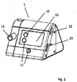
- Fig. 1 shows the basic structure of a device for ventilation (1).
- a breathing gas pump is arranged in a device interior.
- a connecting hose is connected.
- the connecting hose can run an additional pressure measuring hose, which is connectable via a pressure input port to the device housing.
- the device housing has at least one interface (12, 13).
- an operating element (15) is arranged in order to manually specify a dynamic mode of the ventilator.
- the operating element (15) can be arranged in the region of the control panel or be designed as an external or separate operating element.
- a humidifier is adapted laterally.
- control device it is possible for the control device to be suitable and designed to monitor a flow signal and / or a pressure signal and to evaluate it using at least one algorithm in order to type an event.
- the flow signal and / or the Pressure signal are provided by at least one of the control means associated sensor means.
- the sensor means is provided for detecting at least one flow characteristic and / or at least one pressure characteristic of the air flow for the ventilation. The evaluation of flow signals or pressure signals enables a reliable detection and typing of events of the respiration.
- the control device is also particularly suitable and designed to register at least one ventilation parameter based on the flow signal and / or the pressure signal, as described, for example, in US Pat. the respiratory rate, the tidal volume, the minute ventilation, the inspiratory flow and / or the inspiratory pressure and / or the airway resistance.
- control device may be suitable and designed to supply the flow generator with an oscillating control signal.
- the flow generator then generates a respiratory gas flow with a modulated pressure oscillation, which is preferably in the range 1-20 Hz, particularly preferably 2-10 Hz, or even at 4 Hz and pressure stroke of 0.1-1 cm H2O, preferably 0.4 cmH 2 O causes. This pressure stroke also induces an oscillating flow.
- the control device may be suitable and designed to output a corresponding indication to a user in the event of registered respiratory events.
- the indication can be visually and / or acoustically displayed by means of a display device.
- the indication can also be output, for example, by means of an interface to at least one external data processing device.
- Such an indication is particularly advantageous because, knowing the events, the ventilation treatment can be adjusted accordingly. On the other hand, in the absence of the hint a corresponding success of the ventilation treatment can be determined.
- the ventilator can be adjusted dynamically and in particular according to the breathing phase of the user. For example, a respiratory phase change can be detected on the basis of the control device, so that a higher or lower pressure can be provided depending on the respiratory phase.
- the ventilator may be configured as a CPAP or APAP device.
- the respirator 1 can also be designed as a bilevel device be. For example, respirator 1 responds to certain respiratory events, such as snoring, respiratory flattening, and / or obstructive pressure spikes with appropriate ventilation parameter settings. With the respirator 1 shown here, events that occur during respiration or during ventilation are detected and typed.
- the sensor means detects one or more ventilation parameters such as pressure and / or flow and / or ODS signal and delivers corresponding signals to the control device 7.
- the control device 7 analyzes the signals by means of suitable algorithms, so that characteristic signal curves can be recognized and typed as an event , In this case, for example, a parameter extraction with respect to levels and amplitude values, time intervals, envelopes, zero crossings and slopes can be used. In an analysis with regard to time characteristics, for example, periodicities and frequencies are used in a parameter extraction.
- An obstructive apnea (oA) is detected if a greatly reduced one for at least two breaths. Flow volume is detected and / or an ODS increase occurs.
- obstructive hypopnea (oH) is manifested by a reduced flow volume for two consecutive inspirations or by obstructive flattening (a typical flattening of the respiratory curve) of the flow signal.
- Obstructive snoring is recognized by cumulative snoring over at least two consecutive inspirations associated with obstruction or flattening.
- Obstructive flattening is detected by cumulative flattening via at least three inspirations, at least one increase in the inspiratory ODS signal.
- An obstructive event is detected by a significant accumulated inspiratory increase in the ODS signal.
- Snoring is detected by cumulative snoring (at least 3 consecutive inspirations) without inspiratory ODS surge.
- Non-specific flattening is detected by cumulative flattening (at least 3 inspirations).
- a central apnea becomes. detected over a greatly reduced flow volume for 10 seconds without ODS surge or flattening.
- Leakage in the area of the patient interface or mouth and mask leakage is detected by the fact that the target pressure can not be reached and / or the leakage flow is greater than 0.6 l / sec.
- the detected events can then be stored in the memory device and used for ventilation statistics.
- An advantage of the event recognition is that on the basis of the typed events an adaptation of the ventilation can take place, eg an automatic pressure increase with an obstructive apnea. In addition, some diagnostics of certain respiratory disorders can occur.
- a special advantage of the ventilator 1 shown here is the control device 7, which further analyzes the detected events and also registers a Cheyne-Stokes respiration on the basis of a characteristic occurrence of the events. Such an event analysis is exemplary in the FIG. 2 outlined.
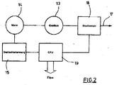
- Fig. 2 shows a schematic block diagram for explaining a part of an internal structure of the device accordingly Fig. 1 .
- a pump device (13) is provided, which is designed as a fan.
- the pumping device (13) is driven by a motor (14).
- a sensor (15) is used, which is connected to a controller (16).
- a sensor (18) for detecting a pressure is arranged in the region of a flow volume line (17) fed by the pumping device (13). Also the Sensor (18) is connected to the controller (16).
- a computing unit (19) is implemented, which carries out a computational combination of the measured values for the pressure and the rotational speed and calculates a current volume flow therefrom.
- the controller (16) as a digital computer, for example as a microprocessor, it is possible to implement the arithmetic unit (19) as part of the sequence programming of the controller (16).
- the controller (16) is also thought to realize the computing unit (19) via components with linear or nonlinear electrical behavior.
- FIG. 2 illustrates a characteristic field which, for an exemplarily selected ventilation system, represents the dependence of the flow volume on the respective pressure.
- FIG. It can be seen in particular that different characteristic curves occur at different rotational speeds of the motor (14).
- the respective characteristic curves consist of approximately parabolic subregions which are connected in an environment of the pressure axis of approximately linear progressions.
- Fig. 4 represents a measured curve (20) of the flow volume and a curve (21) calculated by the controller (16).
- the flow volume is given in l / sec. It can be seen that there is a very broad agreement.
- the respective characteristic curve is determined for the totality of motor (14), pump device (13), line (17) and sensor (18).
- the primary coefficients b ik here represent the mechanical and electrical properties of the overall system and can be determined metrologically. Taking into account the square approaches to the relationship between the pressure and the volume flow and the secondary coefficients a ik of the primary coefficients b ik nine coefficients b ik are to be determined by measurement.
- the simple equation structure makes it possible to recalculate the secondary coefficients a k (n) before each newly calculated value for the volume flow from the known primary coefficients b i .
- the actual value for the volume flow is then determined via the inverse function of the equation listed first.
Landscapes
- Health & Medical Sciences (AREA)
- Life Sciences & Earth Sciences (AREA)
- General Health & Medical Sciences (AREA)
- Public Health (AREA)
- Veterinary Medicine (AREA)
- Biomedical Technology (AREA)
- Heart & Thoracic Surgery (AREA)
- Engineering & Computer Science (AREA)
- Pulmonology (AREA)
- Animal Behavior & Ethology (AREA)
- Hematology (AREA)
- Emergency Medicine (AREA)
- Anesthesiology (AREA)
- Physiology (AREA)
- Physics & Mathematics (AREA)
- Biophysics (AREA)
- Pathology (AREA)
- Medical Informatics (AREA)
- Molecular Biology (AREA)
- Surgery (AREA)
- Measurement Of The Respiration, Hearing Ability, Form, And Blood Characteristics Of Living Organisms (AREA)
- Respiratory Apparatuses And Protective Means (AREA)
Abstract
Description
- Die
EP 0 705 615 beschreibt ein Verfahren zur Steuerung eines Beatmungsgerätes dadurch, dass mit der Oszilloresistometrie die oszillatorische Druckamplitude, die dem Atemwiderstand des Patienten entspricht, kontinuierlich gemessen wird, wobei nach dem Bestimmen des individuellen Atemwiderstandswertes (Basiswert der Druckamplitude) bei Abweichungen von diesem Wert dem Patienten Atemgas unter Druck zugeführt und die Gaszufuhr beendet wird, sobald der Basiswert wieder oder annähernd erreicht ist. Bei diesem Verfahren zur Steuerung und Regelung eines Beatmungsgerätes zur Therapie von Schlafapnoe-Patienten wird dieses Gerät nur dann aktiviert, d. h. es wird dem Patienten nur dann Atemgas unter erhöhtem Druck zugeführt, wenn durch eine Apnoe die Atemtätigkeit des Patienten gestört ist oder sich der Atemwiderstand - und somit auch die gemessene oszillatorische Druckamplitude - durch eine entstehende Apnoe ändert. Eine Störung der Atemtätigkeit des Patienten ist von einer Veränderung des Atemwiderstandes des Patienten begleitet. Dieser Widerstand wird ohne das Befinden des Patienten zu beeinflussen, auf einfache Weise zuverlässig und reproduzierbar über die Veränderungen der oszillatorischen Druckamplitude bestimmt. Im Verlauf einer beginnenden Apnoe bewirken Verengungen oder Erweiterungen der Atemwege eines Patienten Änderungen im Phasenwinkel der oszillatorischen Druckamplitude und des Atemflusses im Vergleich zu den entsprechenden Basiswerten bei normalem oder ungestörtem Atemhub. - Das Beatmungsgerät zur Therapie der Schlafapnoe weist eine Atemmaske auf, die über einen Atemschlauch mit einer als Lüfter ausgebildeten Druckgasquelle verbunden ist. Im Atemschlauch sind vor der Atemmaske die Sensoren einer Einrichtung zum Erzeugen, Messen und Filtern der oszillatorischen Druckamplitude nach dem ORM-Prinzip sowie des Phasenwinkels vorgesehen. Von einer Steuer-Regeleinrichtung, die mit der Einrichtung verbunden und auf den individuellen Basiswert der dem Atemwiderstand des Patienten entsprechenden oszillatorischen Druckamplitude einstellbar ist, wird die Druckgasquelle 3 so aktiviert, dass dem Patienten Atemgas bei signifikanten Veränderungen des Phasenwinkels zugeführt wird. Die Einrichtung 5 umfasst auch eine ventillose Membranpumpe, mit der dem Atemfluss ein sinusförmiger Wechselfluss überlagert wird.
- Die
EP 0 821 977 betrifft ein Verfahren zur Steuerung eines Beatmungsgerätes zur Therapie der Schlafapnoe sowie ein Beatmungsgerät zur Durchführung des Verfahrens, wobei der Phasenwinkel (die zeitliche Differenz zwischen Atemfluss und Atemdruck) und die dem Atemwiderstand entsprechende Druckamplitude gemessen sowie der individuelle Atemwiderstandswert (Basiswert) der Druckamplitude eines Patienten mit Hilfe der Oszilloresistometrie bestimmt und der Atemgasdruck in Abhängigkeit von diesen Größen geregelt werden. - Zur Durchführung einer Ermittlung des Strömungsvolumens ist es beispielsweise bekannt, Sensoren mit temperierbaren Hitzdrähten zu verwenden, die mit temperaturabhängigen Widerständen versehen sind. Bei einer Beheizung eines der Widerstandsdrähte kann im Bereich eines weiteren Hitzdrahtes eine Temperaturveränderung erfasst werden, die vom jeweiligen Strömungsvolumen abhängig ist. Ebenfalls ist es bereits bekannt, über dem Strömungsvolumen ausgesetzte Messbrücken mit temperaturabhängigen Widerständen das Strömungsvolumen zu erfassen, da auch hier Abkühleffekte vom jeweiligen Strömungsvolumen abhängig sind. Die bekannten Sensoren erweisen sich jedoch als relativ aufwendig und teuer.
- Nachteilig ist, dass die Vorrichtung eine Pumpe erfordert, mit der ein oszillierender Wechselfluss erzeugt wird. Nachteilig ist ebenfalls, dass die Signale der Oszilloresietometrie mittels eines Fluss- und/oder Drucksensors aufgezeichnet werden müssen.
- Die Aufgabe der Erfindung besteht in der Bereitstellung einer Vorrichtung, mit der die Messung des oszillatorischen Atemwegswiderstandes während einer Atemtherapie möglich ist ohne eine zusätzliche Erzeugerpumpe oder Sensoren für den Atemgasfluss oder Fluss.
- In der Beschreibung der vorliegenden Erfindung werden die Begriffe Atemgasfluss und Fluss synonym verwendet.
- autoCPAP-Beatmungsvorrichtung, mit einer Steuerung und einem Beatmungsgebläse und einem Drucksensor, wobei die Steuerung einen Controller zur Erzeugung eines ersten Steuersignals aufweist, welches die Drehzahl des Gebläses zur Erzeugung eines unter Druck stehenden Atemgasflusses veranlasst, und wobei die Steuerung einen Controller zur Erzeugung eines periodisch veränderlichen Steuersignals aufweist, welcher das Gebläse derart ansteuert, dass die Drehzahl des Gebläses mit einer Frequenz im Bereich 1- 30 Hz, bevorzugt 1 - 20 Hz oszillierend schwankt, wobei die Steuerung eine Sensoreinrichtung aufweist, die zumindest die momentane Drehzahl des Gebläses ermittelt und/oder den momentanen elektrischen Strom des Gebläses ermittelt und/oder die momentane elektrische Leistung des Gebläses ermittelt zur Bestimmung des von dem Gebläse erzeugten Atemgasflusses und/oder Atemgasvolumens unter Verwendung von in einem Speicher hinterlegten Kenndaten des Gebläses und vom Drucksensor bereitgestellten Druckwerten.
- Diese Aufgabe wird erfindungsgemäß dadurch gelöst, dass sowohl eine Drehzahl des Motors als auch ein Druck im Bereich des Strömungsvolumens messtechnisch erfasst sowie der Steuerung zugeführt werden und dass das Strömungsvolumen von der Steuerung durch eine rechnerische Verknüpfung der Messwerte für den Druck und die Drehzahl ermittelt wird.
- Die erfindungsgemäße Sensoreinrichtung ist bevorzugt kein gegenständlich vorhandener Fluss-Sensor. Die erfindungsgemäße Sensoreinrichtung ist bevorzugt eine Berechnungsvorschrift oder ein Algorithmus, die zumindest die momentane Drehzahl des Gebläses ermittelt und/oder den momentanen elektrischen Strom des Gebläses ermittelt und/oder die momentane elektrische Leistung des Gebläses ermittelt zur Bestimmung des von dem Gebläse erzeugten Atemgasflusses und/oder Atemgasvolumens unter Verwendung von in einem Speicher hinterlegten Kenndaten des Gebläses und vom Drucksensor bereitgestellten Druckwerten.
- Erfingdungsgemäß kann durch die Verwendung der Sensoreinrichtung ein Fluss-Sensor (der zumindest 20 € kostet) eingespart werden.
- Weitere Aufgabe der vorliegenden Erfindung ist es, eine Vorrichtung der einleitend genannten Art derart zu konstruieren, dass eine hohe Messgenauigkeit bei Verwendung einer einfachen Sensoreinrichtung erreicht wird.
- Diese Aufgabe wird erfindungsgemäß dadurch gelöst, dass der Motor mit einer Sensoreinrichtung zur Drehzahlerfassung versehen und im Bereich des Strömungsvolumens ein Sensor zur Druckmessung angeordnet ist, dass der Sensor und die Sensoreinrichtung an die Steuerung angeschlossen sind und dass die Steuerung mit einer Recheneinheit zur Bestimmung des Strömungsvolumens und/oder des Flusses durch eine rechnerische Verknüpfung der Messwerte für den Druck und die Drehzahl versehen ist.
- Die messtechnische Erfassung der Drehzahl des Motors sowie die messtechnische Erfassung des Druckes im Bereich des Strömungsvolumens können mit konstruktiv einfachen Sensoren preiswert und mit hoher Genauigkeit erfolgen. Durch die rechnerische Auswertung dieser Messgrößen im Bereich der Steuerung ist es möglich, unter Berücksichtigung eines mathematischen Modells der strömungstechnischen Eigenschaften der Gesamtanordnung das jeweilige Strömungsvolumen zu ermitteln. Die Berechnung des Strömungsvolumens aus den gemessenen Parametern erfolgt nach vergleichsweise einfachen Berechnungsvorschriften, so dass die Umrechnung beispielsweise unter Verwendung eines einfachen Mikroprozessors durchgeführt werden kann. Alternativ ist es aber auch möglich, eine analoge Ermittlung mit Hilfe von Bauelementen durchzuführen, die geeignete Kennlinien besitzen.
- Eine Ermittlung eines aktuellen Strömungsvolumens wird dadurch unterstützt, dass die rechnerische Verknüpfung unter Berücksichtigung einer Gerätecharakteristik durchgeführt wird, die durch ein Kennlinienfeld definiert wird.
- Zur Ermöglichung einer Ermittlung des Strömungsvolumens mit geringem Zeitaufwand wird vorgeschlagen, dass das Kennlinienfeld vor einer Erfassung des Strömungsvolumens messtechnisch aufgenommen wird und im Beatmungsgerät abgespeichert ist.
- Eine weitere Verkürzung des Zeitaufwandes kann dadurch erfolgen, dass eine tatsächliche physikalische. Abhängigkeit zwischen dem Strömungsvolumen und einem im Bereich des Strömungsvolumens herrschenden Druckes durch eine gemischt quadratische Gleichung angenähert wird.
- Zur Bereitstellung einfacher Berechnungsvorschriften wird vorgeschlagen, dass eine Parametrisierung des Kennlinienfeldes durchgeführt wird.
- Der Fluss wird nicht mittels eines herkömmlichen Sensors bestimmt, sondern anhand eines Kennfeldes aus Drehzahl und Druck ermittelt. Beispielsweise wird der Druck am Geräteausgang ermittelt. Im Rahmen dieser Anmeldung sind daher Sensormittel oder Sensoren die den Fluss ermitteln in Form von Schaltungen und/oder Berechnungen ausgeführt. Beispielsweise können diese Werte, des ermittelten Flusses, noch anhand des Umgebungsdruckes korrigiert werden. Eine weitere Erhöhung der Genauigkeit lässt sich erreichen, wenn zusätzlich oder ergänzend eine Korrektur anhand der Temperatur des Atemgases, beispielsweise am Beatmungsgebläse, und/oder der Luftfeuchte erfolgt. Eine weitere Verbesserung lässt sich dadurch erreichen, wenn verschiedene Kennfelder je nach Zubehörtyp vorgesehen sind Befeuchter ja/nein, Schlauchtyp, Bakterienfilter ja/nein oder Maskentyp. Zudem kann der ermittelte Fluss bei Anschluss eines Befeuchters per Korrekturfaktor modifiziert werden.
Gemäß der vorliegenden Erfindung wird der Fluss von Atemgas nicht mittels eines herkömmlichen Sensors bestimmt, sondern anhand eines Kennfeldes aus Drehzahl und Druck ermittelt. Der so ermittelte Fluss wird durch Verwendung zumindest eines Kompensationsparameters überprüft und möglichweise korrigiert. Als Kompensationsparameter dienen Umgebungsdruck und/oder Temperatur und/oder verwendetes 'Zubehör und/oder die Luftfeuchte und/oder die Leckage und/oder der aktuelle Therapiedruck. Dazu wird. zumindest ein Kompensationsparameter, bevorzugt werden zumindest zwei Kompensationsparameter, sensorisch ermittelt oder rechnerisch bestimmt oder ausgelesen oder vom Nutzer eingegeben. - Der ermittelte Fluss wird zumindest zeitweise unter Berücksichtigung der ermittelten Werte des Kompensationsparameters oder der Kompensationsparameter und unter Nutzung von Kennfeld und/oder linearer Regressionsgleichung und/oder multidimensionaler Regression und/oder Linearisierung und/oder quadratische / exponentielle Gleichungen angepasst.
- Alternativ oder ergänzend kann ein hinterlegter gerätetypischer Kompensationsparameter abgerufen und genutzt werden um den ermittelten Fluss zumindest zeitweise anzupassen.
- Der auf diese Weise ermittelte Gesamtfluss kann weiter separiert werden in Masken-Spülfluss, ungewollten Leckagefluss und respiratorischen Fluss.
- Auf Basis des so ermittelten respiratorischen Flusses erfolgt die FOT-Auswertung. Die FOT-Schwingung wird mit dem Beatmungsgebläse erzeugt. Dazu wird auf den Therapie-Solldruck die 1 - 30 Hz, bevorzugt eine 1 - 20 Hz-Schwingung aufmoduliert und vom Druckregler mit ausgeregelt. Die Schwingung kann auch im Bereich 2 - 10 Hz liegen.
Zur Erzeugung der FOT-Schwingung wird der Solldruck oszillierend vom Controller geändert. Der Druckregler folgt mit dem Ist-Druck. Bei der hohen Frequenz ist das jedoch auch fehlerbehaftet. Je nach Resistance und Compliance von Lunge, Schlauch, Maske, Atemwegen oder anderen Faktoren oszilliert der Ist-Druck also mit einer individuell etwas abweichenden Amplitude. Hier kommt zum ersten Mal der berechnete Fluss ins Spiel. Der Druckregler schätzt den Druckabfall über den Schlauch und sonstiges Zubehör anhand des berechneten Flusses und versucht diesen zu kompensieren. Erst dadurch ist es für den Druckregler möglich, die Vorgabe des Controllers umzusetzen.
Zur Erzeugung der FOT-Schwingung kann alternativ auch nur die Drehzahl mit einer festen Amplitude oszillieren.
Die Durchgängigkeit der Atemwege wird anhand des Quotienten der Amplitude aus berechnetem Fluss und Druck ermittelt. Es wird also ermittelt, wie viel Fluss pro Druck erzeugt werden kann. Sind die Atemwege offen, ist es viel Fluss. Sind sie geschlossen, ist es wenig Fluss. Die Schwelle liegt bei 12,5 l/min / hPa, falls keine Leckage vorliegt. Je höher die Leckage, desto mehr verschiebt sich der Schwellwert, da man bei einem undichten System ohnehin mehr Fluss pro Druckschwankung erzeugen kann. Dabei ist beides relevant: gewollte Leckage (Spülfluss) und ungewollte Leckage (Mund oder Maske undicht). - Während der Apnoe-Klassifikation mit FOT wird der vorgegebene Solldruckwert Pset mit einer sinusförmigen Schwingung mit einer Frequenz von 2-10 Hz, beispielsweise 4 Hz überlagert.
- Dieser Wert (drittes Koordinatensystem in Abbildungen 1 und 2) dient dem Druckregler als Sollgrösse. Bei offenen Atemwegen muss das Gebläse mehr Luft bewegen um die vorgegebene Druckamplitude zu erreichen als im obstruktiven Fall. Damit wird eine Schwingung auf dem Fluss-Signal mit grösserer Amplitude erzeugt (vgl. oberstes Koordinatensystem in Abbildungen 1 und 2: im obstruktiven Fall hat die resultierende Fluss-Schwingung eine Amplitude von ca. 2,5 l/min im Fall der offenen Atemwege von ca. 9 l/min).
- Um ein Signal für die Ausgabe im Obstruktionskanal und die Klassifizierung der Apnoen zu generieren, wird sowohl von der Druck- als auch von der Fluss-Schwingung der Maximalwert der letzten 100 Messpunkte (das entspricht einer Sekunde) bestimmt und dann der Quotient daraus berechnet:

- Alternativ oder ergänzend kann auch rollierend für jeden Abtastschritt die Amplitude der letzten Sekunde ausgewertet werden. Alternativ oder ergänzend kann auch für jede Abtastwert das kleine Delta zum Abtastwert davor ausgewertet wird. Alternativ oder ergänzend kann auch eine Aufsummierung über 2, 3, ... Abtastschritte oder eine Verrechnung mehrerer Abtastschritte über einen Tiefpassfilter zur Glättung erfolgen.
- Alternativ oder ergänzend kann auch für jeden Abtastschritt oder gemittelt über ganz wenige Abtastschritte der Quotient berechnet wird. In der Messung, die den beiden Abbildungen zugrunde liegt, beträgt der Quotient im obstruktiven Fall etwa 5, im Fall offener Atemwege liegt er bei etwa 18.
Dieser Quotient wird anschließend auf einen Wertebereich von 0 - 100 abgebildet (0 entspricht offenen Atemwegen, 100 entspricht blockierten Atemwegen). Dabei werden Effekte, die durch angeschlossenes Zubehör, Leckage oder Umgebungsbedingungen (Temperatur, Luftdruck) entstehen, kompensiert. - Der Quotient wird pro Abtastschritt berechnet, also ca. 100 mal pro Sekunde: Änderung Fluss versus Änderung Druck. Am Ende wird geschaut, ob während der Apnoe mehr als 50% der Zeit der Schwellwert überschritten oder unterschritten wurde.
Statt des Quotient aus Fluss und Druck könnte man auch Drehzahl und Druck, Drehzahl und Fluss etc. verwenden.
Der Schwellwert des FOT könnte neben der Leckage auch je nach Zubehör angepasst werden: Befeuchter ja/nein, Bakterienfilter ja/nein, Schlauchtyp, ...
Außerdem gibt es in der Regel eine obere Grenze, bis zu der obstruktive Apnoen erkannt werden. Sie kann fix sein (bei uns 14 hPa) oder variabel je nach Druckgrenzen, als separater Einstellparameter, je nach Zubehör oder ja nach Eventverlauf des Patienten. Z.B. wenn der Patient fortlaufend bei steigenden Drücken obstruktive Apnoen zeigt, werden sie auch weiterhin als obstruktive Apnoen gewertet. Ist jedoch über einige hPa Druckanstieg keine obstruktive Apnoe mehr aufgetreten, und bei noch höheren Drücken setzen plötzlich welche ein, werden diese als reflektorische Verschlüsse aufgrund des Drucks gewertet. -
Fig. 1 zeigt den grundsätzlichen Aufbau einer Vorrichtung zur Beatmung (1). Im Bereich eines Gerätegehäuses mit Bedienfeld (10) sowie Anzeige (11) ist in einem Geräteinnenraum eine Atemgaspumpe angeordnet. Über eine Kopplung (14) wird ein Verbindungsschlauch angeschlossen. Entlang des Verbindungsschlauches kann ein zusätzlicher Druckmessschlauch verlaufen, der über einen Druckeingangsstutzen mit dem Gerätegehäuse verbindbar ist. Zur Ermöglichung einer Datenübertragung weist das Gerätegehäuse zumindest eine Schnittstelle (12, 13) auf. - Im Bereich des Gerätegehäuses ist ein Bedienelement (15) angeordnet, um manuell einen dynamischen Modus des Beatmungsgerätes vorgeben zu können. Das Bedienelement (15) kann im Bereich des Bedienfeldes angeordnet sein oder als externes oder separates Bedienelement ausgeführt sein.
- Zur Vermeidung eines Austrocknens der Atemwege erweist es sich insbesondere bei längeren Beatmungsphasen als zweckmäßig, eine Befeuchtung der Atemluft durchzuführen. Derartige Beleuchtungen der Atemluft können auch bei anderen Anwendungen realisiert werden. Zur Befeuchtung wird seitlich ein Atemluftbefeuchter adaptiert.
- Es ist möglich, dass die Steuereinrichtung dazu geeignet und ausgebildet ist, ein Flusssignal und/oder ein Drucksignal zu überwachen und anhand wenigstens eines Algorithmus auszuwerten, um ein Ereignis zu typisieren. Das Flusssignal und/oder das Drucksignal werden dabei von wenigstens einem der Steuereinrichtung zugeordneten Sensormittel bereitgestellt. Das Sensormittel ist dabei zur Erfassung wenigstens einer Flusseigenschaft und/oder wenigstens einer Druckeigenschaft des Luftstroms für die Beatmung vorgesehen. Die Auswertung von Flusssignalen bzw. Drucksignalen ermöglicht eine zuverlässige Erkennung und Typisierung von Ereignissen der Atmung.
- Besonders bevorzugt ist die Steuereinrichtung auch dazu geeignet und ausgebildet, anhand des Flusssignals und/oder des Drucksignals wenigstens einen Beatmungsparameter zu registrieren, wie z.B. die Atemfrequenz, das Atemzugvolumen, das Atemminutenvolumen, den Inspirationsfluss und/oder den Inspirationsdruck und/oder den Atemwegswiderstand.
- Die Steuereinrichtung kann ergänzend dazu geeignet und ausgebildet sein, den Strömungsgenerator mit einem oszillierenden Steuersignal zu beaufschlagen. Der Strömungsgenerator erzeugt daraufhin einen Atemgasfluss mit einer aufmodulieren Druckschwingung, die bevorzugt im Bereich 1 - 20 Hz, besonders bevorzugt bei 2 - 10 Hz, oder auch bei 4 Hz liegt und Druckhub von 0,1 - 1 cm H2O, bevorzugt 0,4 cmH2O bewirkt. Dieser Druckhub induziert ebenfalls einen oszillierenden Fluss.
- Die Steuereinrichtung kann dazu geeignet und ausgebildet sein, bei registrierten Atmungsereignissen einen entsprechenden Hinweis an einen Benutzer auszugeben. Beispielsweise kann der Hinweis mittels einer Anzeigeeinrichtung optisch und/oder akustisch angezeigt werden. Der Hinweis kann beispielsweise auch mittels einer Schnittstelle an wenigstens eine externe Datenverarbeitungseinrichtung ausgegeben werden. Ein solcher Hinweis ist besonders vorteilhaft, da in Kenntnis der Ereignisse die Beatmungsbehandlung entsprechend angepasst werden kann. Andererseits kann beim Ausbleiben des Hinweises ein entsprechender Erfolg der Beatmungsbehandlung festgestellt werden.
- Das Beatmungsgerät kann dynamisch und insbesondere je nach Atemphase des Benutzers angepasst werden. Beispielsweise kann anhand der Steuereinrichtung ein Atemphasenwechsel erkannt werden, sodass je nach Atemphase ein höherer bzw. niedrigerer Druck bereitgestellt werden kann. Beispielsweise kann das Beatmungsgerät als ein CPAP- oder APAP-Gerät ausgebildet sein. Das Beatmungsgerät 1 kann auch als ein Bilevel-Gerät ausgebildet sein. Beispielsweise reagiert das Beatmungsgerät 1 auf bestimmte Atemereignisse, wie z.B. Schnarchen, Atemabflachungen und/oder obstruktive Druckspitzen mit entsprechenden Einstellungen der Beatmungsparameter.
Mit dem hier gezeigten Beatmungsgerät 1 werden Ereignisse, die in der Atmung bzw, während der Beatmung auftreten, erkannt und typisiert. Dazu erfasst das Sensormittel einen oder mehrere Beatmungsparameter wie Druck und/oder Fluss und/oder ODS-Signal und liefert entsprechende Signale an die Steuereinrichtung 7. Die Steuereinrichtung 7 analysiert die Signale mittels geeigneter Algorithmen, sodass charakteristische Signalverläufe erkannt und als ein Ereignis typisiert werden können. Dabei kann beispielsweise auf eine Parameterextraktion in Bezug auf Pegel und Amplitudenwerte, Zeitabstände, Einhüllende, Nulldurchgänge und Steigungen zurückgegriffen werden. Bei einer Analyse im Hinblick auf Zeitmerkmale wird beispielsweise bei einer Parametextraktion auf Periodizitäten und Frequenzen zurückgegriffen.
Eine obstruktive Apnoe (oA) wird erkannt, wenn für mindestens zwei Atemzüge ein stark reduziertes. Flussvolumen erkannt wird und/oder ein ODS-Anstieg erfolgt. - Eine obstruktive Hypopnoe (oH) zeigt sich beispielsweise durch ein reduziertes Flussvolumen für zwei aufeinanderfolgende Inspirationen oder durch obstruktives Flattening (eine typische Abflachung der Atemkurve) des Flusssignals.
- Obstruktives Schnarchen (oS) wird durch kumuliertes Schnarchen über zumindest zwei konsekutive Inspirationen einhergehend mit mit Obstruktionen oder Flattening erkannt.
- Obstruktives Flattening (oF) wird durch kumuliertes Flattening über zumindest drei Inspirationen, mindestens einen Anstieg des inspiratorischen ODS-Signals erkannt.
- Ein obstruktives Ereignis (oE) wird durch einen signifikanten kumulierten inspiratorischen Anstieg des ODS-Signals erkannt.
- Schnarchen (S) wird durch kumuliertes Schnarchen (zumindest 3 konsekutive Inspirationen) ohne inspiratorischen ODS-Anstieg erkannt.
- Unspezifisches Flattening (uF) wird durch kumuliertes Flattening (zumindest 3 Inspirationen) erkannt.
- Eine zentrale Apnoe (zA) wird. über ein stark reduziertes Flussvolumen für 10 Sekunden ohne ODS-Anstieg oder Flattening erkannt.
- Eine zentrale Hypopnoe (zH) wird durch ein reduziertes Flussvolumen (2 konsekutive Inspirationen) ohne ODS-Anstieg erkannt
- Eine Leckage im Bereich des Patienteninterface oder eine Mund- und Maskenleckage wird dadurch erkannt, dass der Solldruck kann nicht erreicht wird und/oder der Leckagefluss über 0,6 l/sec beträgt.
- Die erkannten Ereignisse können dann in der Speichereinrichtung abgelegt und für eine Beatmungsstatistik herangezogen werden. Ein Vorteil der Ereigniserkennung ist, dass auf Basis der typisierten Ereignisse eine Anpassung der Beatmung erfolgen kann, z.B. eine automatische Druckanhebung bei einer obstruktiven Apnoe. Zudem kann in einem gewissen Masse eine Diagnostik bestimmter Atemstörungen erfolgen.
Ein besanderer Vorteil des hier gezeigten Beatmungsgerätes 1 ist die Steuereinrichtung 7, welche die erkannten Ereignisse weiter analysiert und anhand eines charakteristischen Auftretens der Ereignisse auch eine CheyneStokes-Atmung registriert. Eine solche Ereignisanalyse ist beispielhaft in derFigur 2 skizziert. -
Fig. 2 zeigt ein schematisches Blockschaltbild zur Erläuterung eines Teiles eines inneren Aufbaues des Gerätes entsprechendFig. 1 . Zur Förderung des Strömungsvolumens an Atemgas ist eine Pumpeinrichtung (13) vorgesehen, die als ein Gebläse ausgebildet ist. Die Pumpeinrichtung (13) wird von einem Motor (14) angetrieben. Zur Erfassung einer Drehzahl des Motors (14) ist ein Sensor (15) verwendet, der an eine Steuerung (16) angeschlossen ist. Im Bereich einer von der Pumpeinrichtung (13) gespeisten Leitung (17) für das Strömungsvolumen ist ein Sensor (18) zur Erfassung eines Druckes angeordnet. Auch der Sensor (18) ist an die Steuerung (16) angeschlossen. - Im Bereich der Steuerung (16) ist eine Recheneinheit (19) implementiert, die eine rechnerische Verknüpfung der Messwerte für den Druck und die Drehzahl vornimmt und hieraus einen aktuellen Volumenfluss berechnet. Bei einer Ausbildung der Steuerung (16) als Digitalrechner, beispielsweise als Mikroprozessor, ist es möglich, die Recheneinheit (19) als Teil der Ablaufprogrammierung der Steuerung (16) zu realisieren. Bei einer analogen Ausbildung der Steuerung (16) ist auch daran gedacht, die Recheneinheit (19) über Bauelemente mit linearem oder nichtlinearem elektrischen Verhalten zu realisieren.
-
Fig. 3 veranschaulicht ein Kennlinienfeld, das für ein beispielhaft gewähltes Beatmungssystem die Abhängigkeit des Strömungsvolumens vom jeweiligen Druck wiedergibt. Es ist insbesondere zu erkennen, dass sich bei unterschiedlichen Drehzahlen des Motors (14) unterschiedliche Kennlinienverläufe ergeben. Die jeweiligen Kennlinien bestehen aus näherungsweise parabelförmigen Teilbereichen, die in einer Umgebung der Druck-Achse von näherungsweise linearen Verläufen verbunden sind. -
Fig. 4 stellt einen gemessenen Verlauf (20) des Strömungsvolumens und einen von der Steuerung (16) berechneten Verlauf (21) gegenüber. Das Strömungsvolumen ist dabei in l/sec angegeben. Es ist zu erkennen, dass eine sehr weitgehende Übereinstimmung vorliegt. - Für eine Realisierung des erfindungsgemäßen Verfahrens sowie bei einem Aufbau der erfindungsgemäßen Vorrichtung wird. messtechnisch das Kennlinienfeld gemäß
Fig. 3 bestimmt. Für unterschiedliche Motordrehzahlen wird dabei für die Gesamtheit aus Motor (14), Pumpeinrichtung(13), Leitung (17) sowie Sensor (18) die jeweilige Kennlinie bestimmt. Für die einzelnen Kennlinien K zu jeder Drehzahl ergibt sich hierbei der Druck P in Abhängigkeit vom Volumenfluss F entsprechend der Gleichung
- Die obige Gleichung stellt eine Annäherung des tatsächlichen Verlaufes dar, es zeigt sich aber, dass diese Annäherung eine gute Übereinstimmung mit dem tatsächlichen Kennlinienverlauf aufweist. Jeder der Sekundärkoeffizienten aki mit i = 0 bis 2 ist von der jeweiligen Drehzahl abhängig. Die obige Gleichung lässt sich deshalb auch in der Form


- Die Primärkoeffizienten bik repräsentieren hier die mechanischen und elektrischen Eigenschaften des Gesamtsystems und können messtechnisch bestimmt werden. Unter Berücksichtigung der quadratischen Ansätze für die Abhängigkeit zwischen dem Druck und dem Volumenfluss sowie den Sekundärkoeffizienten aik von den Primärkoeffizienten bik sind insgesamt neun Koeffizienten bik messtechnisch zu bestimmen.
- Die einfache Gleichungsstruktur ermöglicht es, die Sekundärkoeffizienten ak(n) vor jedem neu zu berechnenden Wert für den Volumenfluss aus den bekannten Primärkoeffizienten bi neu zu berechnen. Der eigentliche Wert für den Volumenfluss wird dann über die Umkehrfunktion der zuerst aufgeführten Gleichung ermittelt.
Claims (16)
- autoCPAP-Beatmungsvorrichtung (1), mit einer Steuerung und einem Beatmungsgebläse und einem Drucksensor, wobei die Steuerung einen Controller zur Erzeugung eines ersten Steuersignals aufweist, welches die Drehzahl des Gebläses zur Erzeugung eines unter Druck stehenden Atemgasflusses veranlasst, und wobei die Steuerung einen Controller zur Erzeugung eines periodisch veränderlichen Steuersignals aufweist, welcher das Gebläse derart ansteuert, dass die Drehzahl des Gebläses mit einer Frequenz im Bereich 1 - 20 Hz oszillierend schwankt, wobei die Steuerung eine Sensoreinrichtung aufweist, die zumindest die momentane Drehzahl des Gebläses ermittelt und/oder den momentanen elektrischen Strom des Gebläses ermittelt und/oder die momentane elektrische Leistung des Gebläses ermittelt zur Bestimmung des von dem Gebläse erzeugten Atemgasflusses und/oder Atemgasvolumens unter Verwendung von in einem Speicher hinterlegten Kenndaten des Gebläses und vom Drucksensor bereitgestellten Druckwerten.
- autoCPAP-Beatmungsvorrichtung (1) nach Anspruch 1 dadurch gekennzeichnet, dass sowohl eine Drehzahl des Motors als auch ein Druck im Bereich des Strömungsvolumens messtechnisch erfasst sowie der Steuerung zugeführt werden und dass das Strömungsvolumen von der Steuerung durch eine rechnerische Verknüpfung der Messwerte für den Druck und die Drehzahl ermittelt wird.
- autoCPAP-Beatmungsvorrichtung (1) nach Anspruch 1 oder 2 dadurch gekennzeichnet, dass der Motor mit einer Sensoreinrichtung zur Drehzahlerfassung versehen und im Bereich des Strömungsvolumens ein Sensor zur Druckmessung angeordnet ist, dass der Sensor und die Sensoreinrichtung an die Steuerung angeschlossen sind und dass die Steuerung mit einer Recheneinheit zur Bestimmung des Strömungsvolumens und/oder des Atemgasflusses durch eine rechnerische Verknüpfung der Messwerte für den Druck und die Drehzahl versehen ist.
- autoCPAP-Beatmungsvorrichtung (1) nach zumindest einem der vorhergehenden Ansprüche dadurch gekennzeichnet, dass das Kennlinienfeld vor einer Erfassung des Strömungsvolumens messtechnisch aufgenommen wird und im Beatmungsgerät abgespeichert ist.
- autoCPAP-Beatmungsvorrichtung (1) nach zumindest einem der vorhergehenden Ansprüche dadurch gekennzeichnet, dass der ermittelte Atemgasfluss zumindest zeitweise unter Berücksichtigung der ermittelten oder abgelegten Werte zumindest eines Kompensationsparameters angepasst wird.
- autoCPAP-Beatmungsvorrichtung (1) nach zumindest einem der vorhergehenden Ansprüche dadurch gekennzeichnet, dass als Kompensationsparameter Umgebungsdruck und/oder Temperatur und/oder verwendetes Zubehör und/oder die Luftfeuchte und/oder die Leckage und/oder der aktuelle Therapiedruck dienen und dass die Kompensationsparameter sensorisch ermittelt oder rechnerisch bestimmt oder ausgelesen oder vom Nutzer eingegeben werden.
- autoCPAP-Beatmungsvorrichtung (1) nach zumindest einem der vorhergehenden Ansprüche dadurch gekennzeichnet, dass der ermittelte Atemgasfluss zumindest zeitweise unter Berücksichtigung der ermittelten Werte des Kompensationsparameters oder der Kompensationsparameter und unter Nutzung von Kennfeld und/oder linearer Regressionsgleichung und/oder multidimensionaler Regression und/oder Linearisierung und/oder quadratische / exponentielle Gleichungen angepasst wird.
- autoCPAP-Beatmungsvorrichtung (1) nach zumindest einem der vorhergehenden Ansprüche dadurch gekennzeichnet, dass ein hinterlegter gerätetypischer Kompensationsparameter abgerufen und genutzt wird um den ermittelten Atemgasfluss zumindest zeitweise anzupassen.
- autoCPAP-Beatmungsvorrichtung (1) nach zumindest einem der vorhergehenden Ansprüche dadurch gekennzeichnet, dass die Werte der Sensoreinrichtung noch anhand des Umgebungsdruckes korrigiert werden.
- autoCPAP-Beatmungsvorrichtung (1) nach zumindest einem der vorhergehenden Ansprüche dadurch gekennzeichnet, dass die Werte der Sensoreinrichtung noch anhand der Temperatur des Atemgases am Beatmungsgebläse und/oder der Luftfeuchtekorrigiert werden.
- autoCPAP-Beatmungsvorrichtung (1) nach zumindest einem der vorhergehenden Ansprüche dadurch gekennzeichnet, dass die Werte der Sensoreinrichtung noch durch spezifische Kennfelder je nach Zubehörtyp korrigiert werden.
- autoCPAP-Beatmungsvorrichtung (1) nach zumindest einem der vorhergehenden Ansprüche dadurch gekennzeichnet, dass die mit dem Beatmungsgebläse erzeugt wird und dazu auf den Therapie-Solldruck die 1 - 20 Hz-Schwingung aufmoduliert und vom Druckregler mit ausgeregelt wird.
- autoCPAP-Beatmungsvorrichtung (1) nach zumindest einem der vorhergehenden Ansprüche dadurch gekennzeichnet, dass zur Erzeugung der der Solldruck oszillierend vom Controller geändert wird.
- autoCPAP-Beatmungsvorrichtung (1) nach zumindest einem der' vorhergehenden Ansprüche dadurch gekennzeichnet, dass insbesondere bei hohen Frequenzen der Druckregler den Druckabfall über den Schlauch und sonstiges Zubehör anhand des berechneten Atemgasflusses abschätzt und versucht diesen zu kompensieren.
- autoCPAP-Beatmungsvorrichtung (1) nach zumindest einem der vorhergehenden Ansprüche dadurch gekennzeichnet, dass die Durchgängigkeit der Atemwege anhand des Quotienten der Amplitude aus berechnetem Atemgasfluss und Druck ermittelt wird.
- autoCPAP-Beatmungsvorrichtung (1) nach zumindest einem der vorhergehenden Ansprüche dadurch gekennzeichnet, dass während der Apnoe-Klassifikation mit FOT der vorgegebene Solldruckwert Pset mit einer sinusförmigen Schwingung mit einer Frequenz von 2-10 Hz, beispielsweise 4 Hz überlagert wird.
Applications Claiming Priority (1)
| Application Number | Priority Date | Filing Date | Title |
|---|---|---|---|
| DE102016007303 | 2016-06-16 |
Publications (2)
| Publication Number | Publication Date |
|---|---|
| EP3263164A1 true EP3263164A1 (de) | 2018-01-03 |
| EP3263164B1 EP3263164B1 (de) | 2020-03-11 |
Family
ID=59650518
Family Applications (1)
| Application Number | Title | Priority Date | Filing Date |
|---|---|---|---|
| EP17001014.4A Active EP3263164B1 (de) | 2016-06-16 | 2017-06-15 | Beatmungsgerät zur apap-beatmung mit oszillatorischem druck |
Country Status (4)
| Country | Link |
|---|---|
| US (1) | US12569632B2 (de) |
| EP (1) | EP3263164B1 (de) |
| CN (1) | CN107519564B (de) |
| DE (1) | DE202017003149U1 (de) |
Families Citing this family (5)
| Publication number | Priority date | Publication date | Assignee | Title |
|---|---|---|---|---|
| EP3537961B1 (de) | 2016-11-10 | 2025-06-25 | The Research Foundation for The State University of New York | System, verfahren und biomarker für verstopfungen der atemwege |
| US11642553B2 (en) | 2017-09-28 | 2023-05-09 | Cleanspace Ip Pty Ltd. | Portable personal respirator and use thereof |
| CN109893736A (zh) * | 2017-12-07 | 2019-06-18 | 北京怡和嘉业医疗科技股份有限公司 | 基于正压通气治疗机的数据处理方法及装置 |
| EP4408264A4 (de) * | 2021-09-29 | 2025-07-09 | ResMed Pty Ltd | Charakterisierungssysteme für die atemtherapie |
| CN118576180B (zh) * | 2024-06-20 | 2025-11-28 | 中国医学科学院生物医学工程研究所 | 呼吸参数测量系统及方法 |
Citations (12)
| Publication number | Priority date | Publication date | Assignee | Title |
|---|---|---|---|---|
| EP0651971A1 (de) * | 1993-11-05 | 1995-05-10 | Resmed Limited | Sensor für Apnoe und Hindernis im Luftweg eines Atmungssystems |
| EP0705615A1 (de) | 1994-09-08 | 1996-04-10 | GOTTLIEB WEINMANN GERÄTE FÜR MEDIZIN UND ARBEITSSCHUTZ GMBH & CO. | Verfahren und Vorrichtung zur Steuerung eines Beatmungsgerätes zur Therapie der Schlafapnoe |
| WO1997010019A1 (en) * | 1995-09-15 | 1997-03-20 | Resmed Limited | Flow estimation and compensation of flow-induced pressure swings in cpap treatment and assisted respiration |
| EP0821977A2 (de) | 1996-07-30 | 1998-02-04 | GOTTLIEB WEINMANN GERÄTE FÜR MEDIZIN UND ARBEITSSCHUTZ GMBH & CO. | Verfahren und Vorrichtung zur Steuerung eines Beatmungsgerätes zur Therapie der Schlafapnoe |
| EP1393767A1 (de) * | 2002-08-20 | 2004-03-03 | Gottlieb Weinmann Geräte für Medizin und Arbeitsschutz GmbH + Co. | Verfahren und Vorrichtung zur Erfassung eines Strömungsvolumens |
| DE202004000848U1 (de) * | 2004-01-20 | 2004-04-08 | Hoffrichter, Helmut | Vorrichtung zur Messung des oszillatorischen Atemwegswiderstandes |
| US6968842B1 (en) * | 2002-04-03 | 2005-11-29 | Ric Investments, Inc. | Measurement of a fluid parameter in a pressure support system |
| WO2006047826A1 (en) * | 2004-11-04 | 2006-05-11 | Resmed Limited | Using motor speed in a pap device to estimate flow |
| WO2008025080A1 (en) * | 2006-08-30 | 2008-03-06 | Resmed Ltd | Distinguishing closed and open respiratory airway apneas by complex admittance values |
| US20120157794A1 (en) * | 2010-12-20 | 2012-06-21 | Robert Goodwin | System and method for an airflow system |
| WO2013042007A1 (en) * | 2011-09-21 | 2013-03-28 | Koninklijke Philips Electronics N.V. | Upper airway resistance measurement device |
| WO2013173219A1 (en) * | 2012-05-14 | 2013-11-21 | Resmed Motor Technologies Inc. | Control of pressure for breathing comfort |
Family Cites Families (17)
| Publication number | Priority date | Publication date | Assignee | Title |
|---|---|---|---|---|
| DE69532011T2 (de) * | 1994-10-14 | 2004-07-29 | Bird Products Corporation, Palm Springs | Ausatmungsventil |
| US5503146A (en) * | 1994-10-26 | 1996-04-02 | Devilbiss Health Care, Inc. | Standby control for CPAP apparatus |
| US5882724A (en) | 1997-04-22 | 1999-03-16 | The Mead Corporation | Ink jet application of hot melt stilts to carbonless paper |
| US6467477B1 (en) * | 1999-03-26 | 2002-10-22 | Respironics, Inc. | Breath-based control of a therapeutic treatment |
| US6401713B1 (en) * | 1999-05-05 | 2002-06-11 | Respironics, Inc. | Apparatus and method of providing continuous positive airway pressure |
| FR2794635B1 (fr) * | 1999-06-14 | 2001-08-03 | Taema | Appareil de diagnostic ou de traitement des troubles respiratoires du sommeil et procede de fonctionnement |
| US7152598B2 (en) * | 2003-06-23 | 2006-12-26 | Invacare Corporation | System and method for providing a breathing gas |
| US7409611B2 (en) * | 2003-06-27 | 2008-08-05 | Texas Instruments Incorporated | Wrapper instruction/data register controls from test access or wrapper ports |
| US7607437B2 (en) * | 2003-08-04 | 2009-10-27 | Cardinal Health 203, Inc. | Compressor control system and method for a portable ventilator |
| US20070044799A1 (en) * | 2005-07-08 | 2007-03-01 | Hete Bernie F | Modular oxygen regulator system and respiratory treatment system |
| AU2008203812B2 (en) * | 2007-08-17 | 2014-10-02 | ResMed Pty Ltd | Methods and Apparatus for Pressure Therapy in the Treatment of Sleep Disordered Breathing |
| US8424521B2 (en) * | 2009-02-27 | 2013-04-23 | Covidien Lp | Leak-compensated respiratory mechanics estimation in medical ventilators |
| US20140330155A1 (en) * | 2011-12-23 | 2014-11-06 | Koninklijke Philips N.V. | Method and apparatus for monitoring and controlling a pressure support device |
| US9993608B2 (en) * | 2012-05-02 | 2018-06-12 | Fisher & Paykel Healthcare Limited | Respiratory humidifier communication systems and methods |
| JP6305994B2 (ja) * | 2012-06-08 | 2018-04-04 | コーニンクレッカ フィリップス エヌ ヴェKoninklijke Philips N.V. | 患者の肺機能をモニタするための方法及びシステム |
| US10327668B2 (en) * | 2013-08-19 | 2019-06-25 | Tel Hashomer Medical Research, Infrastructure & Services Ltd. | Spirometer system and method for determining lung functional residual capacity (FRC) with a non-occluding shutter |
| CN104688232B (zh) * | 2015-03-23 | 2017-12-01 | 北京怡和嘉业医疗科技股份有限公司 | 一种睡眠呼吸暂停的检测方法及设备 |
-
2017
- 2017-06-14 US US15/622,194 patent/US12569632B2/en active Active
- 2017-06-15 DE DE202017003149.3U patent/DE202017003149U1/de active Active
- 2017-06-15 EP EP17001014.4A patent/EP3263164B1/de active Active
- 2017-06-16 CN CN201710458573.2A patent/CN107519564B/zh active Active
Patent Citations (12)
| Publication number | Priority date | Publication date | Assignee | Title |
|---|---|---|---|---|
| EP0651971A1 (de) * | 1993-11-05 | 1995-05-10 | Resmed Limited | Sensor für Apnoe und Hindernis im Luftweg eines Atmungssystems |
| EP0705615A1 (de) | 1994-09-08 | 1996-04-10 | GOTTLIEB WEINMANN GERÄTE FÜR MEDIZIN UND ARBEITSSCHUTZ GMBH & CO. | Verfahren und Vorrichtung zur Steuerung eines Beatmungsgerätes zur Therapie der Schlafapnoe |
| WO1997010019A1 (en) * | 1995-09-15 | 1997-03-20 | Resmed Limited | Flow estimation and compensation of flow-induced pressure swings in cpap treatment and assisted respiration |
| EP0821977A2 (de) | 1996-07-30 | 1998-02-04 | GOTTLIEB WEINMANN GERÄTE FÜR MEDIZIN UND ARBEITSSCHUTZ GMBH & CO. | Verfahren und Vorrichtung zur Steuerung eines Beatmungsgerätes zur Therapie der Schlafapnoe |
| US6968842B1 (en) * | 2002-04-03 | 2005-11-29 | Ric Investments, Inc. | Measurement of a fluid parameter in a pressure support system |
| EP1393767A1 (de) * | 2002-08-20 | 2004-03-03 | Gottlieb Weinmann Geräte für Medizin und Arbeitsschutz GmbH + Co. | Verfahren und Vorrichtung zur Erfassung eines Strömungsvolumens |
| DE202004000848U1 (de) * | 2004-01-20 | 2004-04-08 | Hoffrichter, Helmut | Vorrichtung zur Messung des oszillatorischen Atemwegswiderstandes |
| WO2006047826A1 (en) * | 2004-11-04 | 2006-05-11 | Resmed Limited | Using motor speed in a pap device to estimate flow |
| WO2008025080A1 (en) * | 2006-08-30 | 2008-03-06 | Resmed Ltd | Distinguishing closed and open respiratory airway apneas by complex admittance values |
| US20120157794A1 (en) * | 2010-12-20 | 2012-06-21 | Robert Goodwin | System and method for an airflow system |
| WO2013042007A1 (en) * | 2011-09-21 | 2013-03-28 | Koninklijke Philips Electronics N.V. | Upper airway resistance measurement device |
| WO2013173219A1 (en) * | 2012-05-14 | 2013-11-21 | Resmed Motor Technologies Inc. | Control of pressure for breathing comfort |
Also Published As
| Publication number | Publication date |
|---|---|
| US20170361041A1 (en) | 2017-12-21 |
| US12569632B2 (en) | 2026-03-10 |
| CN107519564B (zh) | 2021-09-07 |
| DE202017003149U1 (de) | 2017-08-02 |
| CN107519564A (zh) | 2017-12-29 |
| EP3263164B1 (de) | 2020-03-11 |
Similar Documents
| Publication | Publication Date | Title |
|---|---|---|
| DE69936735T2 (de) | Bestimmung des maskenanpassdruckes und korrektion der maskenpassung | |
| DE69425113T2 (de) | Abschätzen des Volumenstroms und Erkennen von Atemcyclen für CPAP Beatmung | |
| EP3263164B1 (de) | Beatmungsgerät zur apap-beatmung mit oszillatorischem druck | |
| DE69736808T2 (de) | Determination einer leckluftströmung | |
| DE102007006689B4 (de) | Vorrichtung und Verfahren zur Obstruktionserkennung während Apnoephasen durch eine zusätzliche Druckstufe | |
| EP1727580B1 (de) | Verfahren zur steuerung eines bilevel-geräts sowie bilevel-gerät | |
| DE10322964B4 (de) | Steuergerät für Antischnarchgerät sowie Antischnarchgerät | |
| EP2923720B1 (de) | Vorrichtung zur therapie periodischer atmung | |
| DE10139881A1 (de) | Vorrichtung zur Zufuhr eines Atemgases und Verfahren zur Steuerung derselben | |
| DE102005010488A1 (de) | Vorrichtung zur Verabreichung eines Atemgases und Verfahren zur Einstellung zumindest zeitweise alternierender Atemgasdrücke | |
| EP3653248A2 (de) | Beatmungsgeräte sowie steuerverfahren für beatmungsgeräte | |
| EP3730174A1 (de) | System zur atemgasversorgung und verfahren | |
| US20210213217A1 (en) | Airway anomaly recognition method, ventilation device, and storage medium | |
| EP3156091A1 (de) | Vorrichtung zur überwachung einer diskonnektion | |
| EP1878457A2 (de) | Beatmungsgerät zur Behandlung von obstruktiver Schlafapnoe und Verfahren zu dessen Steuerung | |
| EP2989978A1 (de) | Beatmungsgerät und verfahren für ein beatmungsgerät | |
| EP1706162A1 (de) | Beatmungsgerät zur therapie der schlafapnoe sowie verfahren zu dessen steuerung | |
| WO2021018691A1 (de) | Vorrichtung zur unterstützenden beatmung eines lebewesens und computerprogramm | |
| DE102007054390A1 (de) | Verfahren zur Erfassung eines rückgeatmeten Ausatemgasvolumens in einem Beatmungssystem | |
| DE102014012805A1 (de) | Beatmungsgerät und Verfahren für ein Beatmungsgerät | |
| EP3827859B1 (de) | Vorrichtung zur veränderung des atemgas-druckes in abhängigkeit von einem mass der herzleistung | |
| EP3061481A1 (de) | Verfahren und vorrichtung zur volumenbhängigen triggerung der ausatemphase | |
| DE102016008142A1 (de) | Vorrichtung zum Bereitstellen zyklischer Beatmung und Verfahren zum Ermitteln der Parameter einer zyklischen Beatmung | |
| DE202005017045U1 (de) | Vorrichtung zur Zufuhr eines Atemgases | |
| EP3524306A1 (de) | Beatmungsgerät sowie steuer- und testverfahren |
Legal Events
| Date | Code | Title | Description |
|---|---|---|---|
| PUAI | Public reference made under article 153(3) epc to a published international application that has entered the european phase |
Free format text: ORIGINAL CODE: 0009012 |
|
| STAA | Information on the status of an ep patent application or granted ep patent |
Free format text: STATUS: THE APPLICATION HAS BEEN PUBLISHED |
|
| AK | Designated contracting states |
Kind code of ref document: A1 Designated state(s): AL AT BE BG CH CY CZ DE DK EE ES FI FR GB GR HR HU IE IS IT LI LT LU LV MC MK MT NL NO PL PT RO RS SE SI SK SM TR |
|
| AX | Request for extension of the european patent |
Extension state: BA ME |
|
| STAA | Information on the status of an ep patent application or granted ep patent |
Free format text: STATUS: REQUEST FOR EXAMINATION WAS MADE |
|
| 17P | Request for examination filed |
Effective date: 20180703 |
|
| RBV | Designated contracting states (corrected) |
Designated state(s): AL AT BE BG CH CY CZ DE DK EE ES FI FR GB GR HR HU IE IS IT LI LT LU LV MC MK MT NL NO PL PT RO RS SE SI SK SM TR |
|
| STAA | Information on the status of an ep patent application or granted ep patent |
Free format text: STATUS: EXAMINATION IS IN PROGRESS |
|
| 17Q | First examination report despatched |
Effective date: 20181127 |
|
| RIC1 | Information provided on ipc code assigned before grant |
Ipc: A61M 16/10 20060101ALN20190926BHEP Ipc: A61M 16/00 20060101AFI20190926BHEP Ipc: A61B 5/08 20060101ALN20190926BHEP |
|
| GRAP | Despatch of communication of intention to grant a patent |
Free format text: ORIGINAL CODE: EPIDOSNIGR1 |
|
| STAA | Information on the status of an ep patent application or granted ep patent |
Free format text: STATUS: GRANT OF PATENT IS INTENDED |
|
| RIC1 | Information provided on ipc code assigned before grant |
Ipc: A61M 16/00 20060101AFI20191008BHEP Ipc: A61B 5/08 20060101ALN20191008BHEP Ipc: A61M 16/10 20060101ALN20191008BHEP |
|
| INTG | Intention to grant announced |
Effective date: 20191108 |
|
| GRAS | Grant fee paid |
Free format text: ORIGINAL CODE: EPIDOSNIGR3 |
|
| GRAJ | Information related to disapproval of communication of intention to grant by the applicant or resumption of examination proceedings by the epo deleted |
Free format text: ORIGINAL CODE: EPIDOSDIGR1 |
|
| GRAL | Information related to payment of fee for publishing/printing deleted |
Free format text: ORIGINAL CODE: EPIDOSDIGR3 |
|
| STAA | Information on the status of an ep patent application or granted ep patent |
Free format text: STATUS: EXAMINATION IS IN PROGRESS |
|
| GRAR | Information related to intention to grant a patent recorded |
Free format text: ORIGINAL CODE: EPIDOSNIGR71 |
|
| STAA | Information on the status of an ep patent application or granted ep patent |
Free format text: STATUS: GRANT OF PATENT IS INTENDED |
|
| GRAA | (expected) grant |
Free format text: ORIGINAL CODE: 0009210 |
|
| STAA | Information on the status of an ep patent application or granted ep patent |
Free format text: STATUS: THE PATENT HAS BEEN GRANTED |
|
| INTC | Intention to grant announced (deleted) | ||
| RIC1 | Information provided on ipc code assigned before grant |
Ipc: A61M 16/10 20060101ALN20200116BHEP Ipc: A61M 16/00 20060101AFI20200116BHEP Ipc: A61B 5/08 20060101ALN20200116BHEP |
|
| RIC1 | Information provided on ipc code assigned before grant |
Ipc: A61B 5/08 20060101ALN20200129BHEP Ipc: A61M 16/10 20060101ALN20200129BHEP Ipc: A61M 16/00 20060101AFI20200129BHEP |
|
| AK | Designated contracting states |
Kind code of ref document: B1 Designated state(s): AL AT BE BG CH CY CZ DE DK EE ES FI FR GB GR HR HU IE IS IT LI LT LU LV MC MK MT NL NO PL PT RO RS SE SI SK SM TR |
|
| INTG | Intention to grant announced |
Effective date: 20200131 |
|
| REG | Reference to a national code |
Ref country code: GB Ref legal event code: FG4D Free format text: NOT ENGLISH |
|
| REG | Reference to a national code |
Ref country code: CH Ref legal event code: EP |
|
| REG | Reference to a national code |
Ref country code: AT Ref legal event code: REF Ref document number: 1242376 Country of ref document: AT Kind code of ref document: T Effective date: 20200315 |
|
| REG | Reference to a national code |
Ref country code: IE Ref legal event code: FG4D Free format text: LANGUAGE OF EP DOCUMENT: GERMAN |
|
| REG | Reference to a national code |
Ref country code: DE Ref legal event code: R096 Ref document number: 502017004129 Country of ref document: DE |
|
| REG | Reference to a national code |
Ref country code: NL Ref legal event code: FP |
|
| PG25 | Lapsed in a contracting state [announced via postgrant information from national office to epo] |
Ref country code: RS Free format text: LAPSE BECAUSE OF FAILURE TO SUBMIT A TRANSLATION OF THE DESCRIPTION OR TO PAY THE FEE WITHIN THE PRESCRIBED TIME-LIMIT Effective date: 20200311 Ref country code: FI Free format text: LAPSE BECAUSE OF FAILURE TO SUBMIT A TRANSLATION OF THE DESCRIPTION OR TO PAY THE FEE WITHIN THE PRESCRIBED TIME-LIMIT Effective date: 20200311 Ref country code: NO Free format text: LAPSE BECAUSE OF FAILURE TO SUBMIT A TRANSLATION OF THE DESCRIPTION OR TO PAY THE FEE WITHIN THE PRESCRIBED TIME-LIMIT Effective date: 20200611 |
|
| PG25 | Lapsed in a contracting state [announced via postgrant information from national office to epo] |
Ref country code: GR Free format text: LAPSE BECAUSE OF FAILURE TO SUBMIT A TRANSLATION OF THE DESCRIPTION OR TO PAY THE FEE WITHIN THE PRESCRIBED TIME-LIMIT Effective date: 20200612 Ref country code: BG Free format text: LAPSE BECAUSE OF FAILURE TO SUBMIT A TRANSLATION OF THE DESCRIPTION OR TO PAY THE FEE WITHIN THE PRESCRIBED TIME-LIMIT Effective date: 20200611 Ref country code: HR Free format text: LAPSE BECAUSE OF FAILURE TO SUBMIT A TRANSLATION OF THE DESCRIPTION OR TO PAY THE FEE WITHIN THE PRESCRIBED TIME-LIMIT Effective date: 20200311 Ref country code: LV Free format text: LAPSE BECAUSE OF FAILURE TO SUBMIT A TRANSLATION OF THE DESCRIPTION OR TO PAY THE FEE WITHIN THE PRESCRIBED TIME-LIMIT Effective date: 20200311 Ref country code: SE Free format text: LAPSE BECAUSE OF FAILURE TO SUBMIT A TRANSLATION OF THE DESCRIPTION OR TO PAY THE FEE WITHIN THE PRESCRIBED TIME-LIMIT Effective date: 20200311 |
|
| REG | Reference to a national code |
Ref country code: LT Ref legal event code: MG4D |
|
| PG25 | Lapsed in a contracting state [announced via postgrant information from national office to epo] |
Ref country code: SK Free format text: LAPSE BECAUSE OF FAILURE TO SUBMIT A TRANSLATION OF THE DESCRIPTION OR TO PAY THE FEE WITHIN THE PRESCRIBED TIME-LIMIT Effective date: 20200311 Ref country code: LT Free format text: LAPSE BECAUSE OF FAILURE TO SUBMIT A TRANSLATION OF THE DESCRIPTION OR TO PAY THE FEE WITHIN THE PRESCRIBED TIME-LIMIT Effective date: 20200311 Ref country code: RO Free format text: LAPSE BECAUSE OF FAILURE TO SUBMIT A TRANSLATION OF THE DESCRIPTION OR TO PAY THE FEE WITHIN THE PRESCRIBED TIME-LIMIT Effective date: 20200311 Ref country code: EE Free format text: LAPSE BECAUSE OF FAILURE TO SUBMIT A TRANSLATION OF THE DESCRIPTION OR TO PAY THE FEE WITHIN THE PRESCRIBED TIME-LIMIT Effective date: 20200311 Ref country code: SM Free format text: LAPSE BECAUSE OF FAILURE TO SUBMIT A TRANSLATION OF THE DESCRIPTION OR TO PAY THE FEE WITHIN THE PRESCRIBED TIME-LIMIT Effective date: 20200311 Ref country code: PT Free format text: LAPSE BECAUSE OF FAILURE TO SUBMIT A TRANSLATION OF THE DESCRIPTION OR TO PAY THE FEE WITHIN THE PRESCRIBED TIME-LIMIT Effective date: 20200805 Ref country code: IS Free format text: LAPSE BECAUSE OF FAILURE TO SUBMIT A TRANSLATION OF THE DESCRIPTION OR TO PAY THE FEE WITHIN THE PRESCRIBED TIME-LIMIT Effective date: 20200711 Ref country code: CZ Free format text: LAPSE BECAUSE OF FAILURE TO SUBMIT A TRANSLATION OF THE DESCRIPTION OR TO PAY THE FEE WITHIN THE PRESCRIBED TIME-LIMIT Effective date: 20200311 |
|
| REG | Reference to a national code |
Ref country code: DE Ref legal event code: R097 Ref document number: 502017004129 Country of ref document: DE |
|
| PLBE | No opposition filed within time limit |
Free format text: ORIGINAL CODE: 0009261 |
|
| STAA | Information on the status of an ep patent application or granted ep patent |
Free format text: STATUS: NO OPPOSITION FILED WITHIN TIME LIMIT |
|
| PG25 | Lapsed in a contracting state [announced via postgrant information from national office to epo] |
Ref country code: MC Free format text: LAPSE BECAUSE OF FAILURE TO SUBMIT A TRANSLATION OF THE DESCRIPTION OR TO PAY THE FEE WITHIN THE PRESCRIBED TIME-LIMIT Effective date: 20200311 Ref country code: ES Free format text: LAPSE BECAUSE OF FAILURE TO SUBMIT A TRANSLATION OF THE DESCRIPTION OR TO PAY THE FEE WITHIN THE PRESCRIBED TIME-LIMIT Effective date: 20200311 Ref country code: DK Free format text: LAPSE BECAUSE OF FAILURE TO SUBMIT A TRANSLATION OF THE DESCRIPTION OR TO PAY THE FEE WITHIN THE PRESCRIBED TIME-LIMIT Effective date: 20200311 Ref country code: IT Free format text: LAPSE BECAUSE OF FAILURE TO SUBMIT A TRANSLATION OF THE DESCRIPTION OR TO PAY THE FEE WITHIN THE PRESCRIBED TIME-LIMIT Effective date: 20200311 |
|
| 26N | No opposition filed |
Effective date: 20201214 |
|
| PG25 | Lapsed in a contracting state [announced via postgrant information from national office to epo] |
Ref country code: SI Free format text: LAPSE BECAUSE OF FAILURE TO SUBMIT A TRANSLATION OF THE DESCRIPTION OR TO PAY THE FEE WITHIN THE PRESCRIBED TIME-LIMIT Effective date: 20200311 Ref country code: PL Free format text: LAPSE BECAUSE OF FAILURE TO SUBMIT A TRANSLATION OF THE DESCRIPTION OR TO PAY THE FEE WITHIN THE PRESCRIBED TIME-LIMIT Effective date: 20200311 |
|
| PG25 | Lapsed in a contracting state [announced via postgrant information from national office to epo] |
Ref country code: LU Free format text: LAPSE BECAUSE OF NON-PAYMENT OF DUE FEES Effective date: 20200615 |
|
| REG | Reference to a national code |
Ref country code: BE Ref legal event code: MM Effective date: 20200630 |
|
| PG25 | Lapsed in a contracting state [announced via postgrant information from national office to epo] |
Ref country code: IE Free format text: LAPSE BECAUSE OF NON-PAYMENT OF DUE FEES Effective date: 20200615 |
|
| PG25 | Lapsed in a contracting state [announced via postgrant information from national office to epo] |
Ref country code: BE Free format text: LAPSE BECAUSE OF NON-PAYMENT OF DUE FEES Effective date: 20200630 |
|
| PG25 | Lapsed in a contracting state [announced via postgrant information from national office to epo] |
Ref country code: TR Free format text: LAPSE BECAUSE OF FAILURE TO SUBMIT A TRANSLATION OF THE DESCRIPTION OR TO PAY THE FEE WITHIN THE PRESCRIBED TIME-LIMIT Effective date: 20200311 Ref country code: MT Free format text: LAPSE BECAUSE OF FAILURE TO SUBMIT A TRANSLATION OF THE DESCRIPTION OR TO PAY THE FEE WITHIN THE PRESCRIBED TIME-LIMIT Effective date: 20200311 Ref country code: CY Free format text: LAPSE BECAUSE OF FAILURE TO SUBMIT A TRANSLATION OF THE DESCRIPTION OR TO PAY THE FEE WITHIN THE PRESCRIBED TIME-LIMIT Effective date: 20200311 |
|
| PG25 | Lapsed in a contracting state [announced via postgrant information from national office to epo] |
Ref country code: MK Free format text: LAPSE BECAUSE OF FAILURE TO SUBMIT A TRANSLATION OF THE DESCRIPTION OR TO PAY THE FEE WITHIN THE PRESCRIBED TIME-LIMIT Effective date: 20200311 Ref country code: AL Free format text: LAPSE BECAUSE OF FAILURE TO SUBMIT A TRANSLATION OF THE DESCRIPTION OR TO PAY THE FEE WITHIN THE PRESCRIBED TIME-LIMIT Effective date: 20200311 |
|
| P01 | Opt-out of the competence of the unified patent court (upc) registered |
Effective date: 20230524 |
|
| REG | Reference to a national code |
Ref country code: AT Ref legal event code: MM01 Ref document number: 1242376 Country of ref document: AT Kind code of ref document: T Effective date: 20220615 |
|
| PG25 | Lapsed in a contracting state [announced via postgrant information from national office to epo] |
Ref country code: AT Free format text: LAPSE BECAUSE OF NON-PAYMENT OF DUE FEES Effective date: 20220615 |
|
| PGFP | Annual fee paid to national office [announced via postgrant information from national office to epo] |
Ref country code: DE Payment date: 20250618 Year of fee payment: 9 |
|
| PGFP | Annual fee paid to national office [announced via postgrant information from national office to epo] |
Ref country code: GB Payment date: 20250620 Year of fee payment: 9 |
|
| PGFP | Annual fee paid to national office [announced via postgrant information from national office to epo] |
Ref country code: NL Payment date: 20250618 Year of fee payment: 9 |
|
| PGFP | Annual fee paid to national office [announced via postgrant information from national office to epo] |
Ref country code: FR Payment date: 20250618 Year of fee payment: 9 |
|
| PGFP | Annual fee paid to national office [announced via postgrant information from national office to epo] |
Ref country code: CH Payment date: 20250701 Year of fee payment: 9 |