EP3263204A1 - Druck- und/oder vakuumfiltervorrichtung - Google Patents
Druck- und/oder vakuumfiltervorrichtung Download PDFInfo
- Publication number
- EP3263204A1 EP3263204A1 EP17178026.5A EP17178026A EP3263204A1 EP 3263204 A1 EP3263204 A1 EP 3263204A1 EP 17178026 A EP17178026 A EP 17178026A EP 3263204 A1 EP3263204 A1 EP 3263204A1
- Authority
- EP
- European Patent Office
- Prior art keywords
- longitudinal
- edge
- transverse
- filter medium
- filter
- Prior art date
- Legal status (The legal status is an assumption and is not a legal conclusion. Google has not performed a legal analysis and makes no representation as to the accuracy of the status listed.)
- Granted
Links
Images

Classifications
-
- B—PERFORMING OPERATIONS; TRANSPORTING
- B01—PHYSICAL OR CHEMICAL PROCESSES OR APPARATUS IN GENERAL
- B01D—SEPARATION
- B01D33/00—Filters with filtering elements which move during the filtering operation
- B01D33/06—Filters with filtering elements which move during the filtering operation with rotary cylindrical filtering surfaces, e.g. hollow drums
- B01D33/067—Construction of the filtering drums, e.g. mounting or sealing arrangements
-
- B—PERFORMING OPERATIONS; TRANSPORTING
- B01—PHYSICAL OR CHEMICAL PROCESSES OR APPARATUS IN GENERAL
- B01D—SEPARATION
- B01D33/00—Filters with filtering elements which move during the filtering operation
- B01D33/06—Filters with filtering elements which move during the filtering operation with rotary cylindrical filtering surfaces, e.g. hollow drums
- B01D33/073—Filters with filtering elements which move during the filtering operation with rotary cylindrical filtering surfaces, e.g. hollow drums arranged for inward flow filtration
Definitions
- the present invention relates to a pressure and/or vacuum filter device comprising a filter drum.
- Such pressure and/or vacuum filter devices are used, e.g., for filtering out a solid from a solid-liquid-suspension, wherein the filter drum is provided on its outer side with a filter medium, on which, during the filter process, the solid to be filtered out, sticks, wherein liquid passes therethrough.
- the invention provides a pressure and/or vacuum filter device which allows an easy, quick and reliable fixation of the filter medium on the filter drum.
- a pressure and/or vacuum filter device comprising a filter drum which defines a filter drum longitudinal-axis and which comprises a filter drum circumferential-wall which extends around the filter drum longitudinal-axis, a filter medium (e.g., a filter cloth in form, e.g., of a plastic and/or metal fabric) which is arranged on an outer side of the filter drum circumferential-wall, and a plurality of fixation devices, by means of which the filter medium is fixedly attached to the filter drum circumferential-wall, wherein the filter medium comprises a plurality of (e.g.
- filter medium piece longitudinal-edges which are arranged opposite to each other and which are at least for the most part a non-patched (that is, e.g., seamless (such as, e.g., sutureless and glueless)) part (e.g. component) of the filter cloth material, as well as filter medium piece transverse-edges, which are arranged opposite to each other and which, e.g., are also at least for the most part a non-patched (that is, e.g., seamless (such as, e.g., sutureless and glueless)) part (e.g.
- the filter medium piece longitudinal-edges and/or the filter medium piece transverse-edges thus are also at least for the most part a seamless (that is, e.g., one piece seamless) part (e.g. component) of the corresponding filter medium piece), and which (filter medium pieces) extend with their filter medium piece longitudinal-edges parallel to the filter drum longitudinal-axis as well as adjacently to each other to thereby form an at least for the most part (e.g., an at least substantially) complete (e.g., closed) filter medium surface
- the plurality of fixation devices comprises a plurality of elongated longitudinal-edge receiving grooves which each define a longitudinal-edge receiving groove longitudinal-axis and each have an elongated (e.g., at least for the most part or, e.g., substantially continuous) longitudinal-edge receiving groove access opening, which extends along the longitudinal-edge receiving groove longitudinal-axis, and which are formed on the filter drum circumferential-wall and extend with their longitudinal-edge
- the plurality of fixation devices further comprises a plurality of elongated longitudinal-edge holding bodies, which each (e.g., respectively) define a longitudinal-edge holding body longitudinal-axis and which are received in a respectively assigned longitudinal-edge receiving groove (of the longitudinal-edge receiving grooves) and which extend with their longitudinal-edge holding body longitudinal-axis parallel to the longitudinal-edge receiving groove longitudinal-axis of the corresponding longitudinal-edge receiving groove and which each have a longitudinal-edge holding body cross-sectional diameter which is larger than a width of the longitudinal-edge receiving groove access opening of the corresponding longitudinal-edge receiving groove to thereby hold the respective filter medium piece longitudinal-edge together with its flat ribbon shaped filter medium piece longitudinal-edge reinforcement within the respectively assigned undercut (e.g., in at least a form-fit manner,
- the filter cloth material of the respective (e.g., each) filter medium piece is, e.g., formed itself at least for the most part (e.g., at least substantially) in a seamless (e.g., sutureless and glueless) (e.g., respectively one piece seamless) manner, which, e.g., means that the area (e.g.
- a regular and uniform filter cloth material e.g., filter fabric cloth material
- the pressure and/or vacuum filter device may be provided with a basin (e.g., a pan), in which the solid liquid suspension is contained and into which a lower portion of the filter drum engages.
- the filter drum is, e.g., rotatable about its filter drum longitudinal-axis so that, in a continuous manner, the whole circumferential area (e.g., circumferential surface) of the filter drum can be, e.g., will be, successively immerged into the solid liquid suspension which is present in the basin.
- the liquid can, e.g., radially (with respect to the filter drum longitudinal-axis) pass through the filter medium and the drum circumferential-wall from the outside and can get into conduits (e.g.
- tubes) of the pressure and/or vacuum filter device which (conduits) are arranged in the interior of the filter drum (inner tubing) and via which conduits the liquid is discharged from the filter drum in a controlled manner (e.g., via a control head which is arranged on an axial end portion of the filter drum and which, e.g, is provided in form of a control disk assembly).
- the filter drum and the basin may be arranged in a sealed casing of the pressure and/or vacuum filter device, within which, with respect to the conduits, a larger pressure will be and/or can be established.
- one or more intermediate pieces e.g., one or more filter cell insertion parts
- conduits e.g., tubes
- Such filter cell insertion parts may also be used as a drainage device in case of an inner tubing, via which (cell insertion parts) the liquid is guided to the conduits.
- the respective (e.g. each) longitudinal-edge receiving groove access opening and/or the respective (e.g. each) transverse-edge receiving groove access opening radially (with respect to the filter drum longitudinal-axis) faces toward the outside and/or is radially open towards the outside and/or is radially exposed towards the outside and can thereby be accessed.
- the filter drum circumferential-wall may be divided in a plurality of filter cells, to which a respective filter medium piece is respectively assigned.
- the filter cells may be separated from each other in circumferential direction of the filter drum, e.g., by means of the longitudinal-edge receiving grooves and may be limited in longitudinal direction of the filter drum (that is, along the filter drum longitudinal-axis) by transverse-edge receiving grooves which will be discussed in further detail below.
- transverse-edge receiving groove may only be formed at a respective longitudinal end of the filter drum, whereby, e.g., a/the respective filter medium piece continuously extends from one longitudinal end portion of the filter drum to the opposite other longitudinal end portion of the filter drum.
- a respective filter cell insertion part may be arranged between the respective filter medium piece and the filter drum circumferential-wall, which (filter cell insertion part) is a part of the pressure and/or vacuum filter device and which, e.g., is assigned to the respectively assigned filter cell and on and/or by which the corresponding filter medium piece is radially supported and which itself is supported on the outer side of the filter drum circumferential-wall.
- the respective (e.g. each) filter cell insertion part may be used and/or provided in a manner as an above-described intermediate piece.
- the respective (e.g. each) filter cell insertion part is radially (with respect to the filter drum longitudinal-axis) liquid permeable.
- the filter cell insertion parts may be connected to each other, e.g., via separation ledges which extend along the filter drum longitudinal-direction, and/or via ring ledges which extend in circumferential direction of the filter drum around (e.g., completely around) the filter drum, wherein the respective longitudinal-edge receiving groove may be formed in a respectively assigned separation ledge and/or wherein the respective transverse-edge receiving groove may be formed in a respective ring ledge.
- the separation ledges and/or the ring ledges are part of the filter drum and/or are fixedly connected to the filter drum.
- One or more of the longitudinal-edge holding bodies or the respective longitudinal-edge holding body may be formed by a rigid cylindrical rod or by a flexible string or a flexible round cord or by a cylindrical helix-structure with a helix-structure cross-section transverse to the longitudinal-edge holding body longitudinal-direction, which, with respect to the longitudinal-edge holding body longitudinal-axis, is/are angular flexible and is/are rigid in radial direction of its helix-structure cross-section.
- the (said) plurality of fixation devices may further comprise a plurality of elongated transverse-edge receiving grooves which each (e.g., respectively) define a transverse-edge receiving groove longitudinal-axis and (each) have an elongated transverse-edge receiving groove access opening, which extends along the transverse-edge receiving groove longitudinal-axis, and which are formed on the filter drum circumferential-wall and extend with their (respective) transverse-edge receiving groove longitudinal-axis in (a) circumferential direction of the filter drum as well as are spaced from each other in longitudinal direction of the filter drum and into which the filter medium piece transverse-edges engage via the correspondingly assigned transverse-edge receiving groove access opening, wherein the respective transverse-edge receiving groove is provided, with respect to the transverse-edge receiving groove longitudinal-axis, at both sides with a respective elongated undercut which (e.g., at least for the most part continuously) extends along the transverse-edge receiving groove longitudinal-axis and which is assigned to a
- the plurality of fixation devices further comprises/comprise a plurality of elongated transverse-edge holding bodies which respectively (e.g., each) define a transverse-edge holding body longitudinal-axis and which are received in a respectively assigned transverse-edge receiving groove and extend with their transverse-edge holding body longitudinal-axis parallel to the transverse-edge receiving groove longitudinal-axis of the corresponding transverse-edge receiving groove and which respectively (e.g.
- each) have a transverse-edge holding body cross-sectional diameter which is larger than the width of the transverse-edge receiving groove access opening of the corresponding transverse-edge receiving groove to thereby hold the respective filter medium piece transverse-edge together with its flat ribbon shaped filter medium transverse-edge reinforcement in the respectively assigned undercut (e.g., at least in a form-fit manner or in a form-and-force-fit manner).
- the respective (e.g., each) filter medium longitudinal-edge reinforcement and/or the respective filter medium transverse-edge reinforcement is, e.g., formed as a (respective) elongated reinforcement flat ribbon which defines a reinforcement flat ribbon longitudinal-axis and which extends with its reinforcement flat ribbon longitudinal-axis (at least substantially continuously) parallel to and/or along the corresponding filter medium piece longitudinal-edge and/or the corresponding filter medium piece transverse-edge.
- One or more of the transverse-edge holding bodies or the respective transverse-edge holding body may, e.g., be formed by a flexible string or a flexible round cord or may, e.g., also be formed by a (e.g., cylindrical) helix-structure which has a helix-structure cross-section transverse to the transverse-edge holding body longitudinal-direction and which (helix-structure) is angular flexible with respect to the transverse-edge holding body longitudinal-axis and is rigid in radial direction of its helix-structure cross-section.
- a e.g., cylindrical helix-structure which has a helix-structure cross-section transverse to the transverse-edge holding body longitudinal-direction and which (helix-structure) is angular flexible with respect to the transverse-edge holding body longitudinal-axis and is rigid in radial direction of its helix-structure cross-section.
- the helix-structure of the respective transverse-edge holding body and/or of the respective longitudinal-edge holding body may, e.g., be made of a metal material (e.g., a steel material) or of a plastic material, such as, e.g., of a metal or plastic wire which is bend and/or extends around the transverse-edge holding body longitudinal-axis and/or around the longitudinal-edge holding body longitudinal-axis, respectively, in a helical manner (wherein it keeps a (substantially) equal (e.g. same) helix-structure cross-sectional diameter).
- a metal material e.g., a steel material
- plastic material such as, e.g., of a metal or plastic wire which is bend and/or extends around the transverse-edge holding body longitudinal-axis and/or around the longitudinal-edge holding body longitudinal-axis, respectively, in a helical manner (wherein it keeps a (substantially) equal (e.g. same) helix-
- the radial rigidity of the respective helix-structure is, e.g., (determined) such that the helix-structure cannot automatically (via radial deformation) get out of the corresponding longitudinal-edge receiving groove and/or out of the corresponding transverse-edge receiving groove via the respective longitudinal-edge receiving groove access opening and/or via the respective transverse-edge receiving groove access opening, respectively.
- the respective elongated longitudinal-edge holding body may, e.g., be axially (in direction of the filter drum longitudinal-axis and/or along the corresponding longitudinal-edge receiving groove longitudinal-axis) inserted (e.g., in a sliding manner) into the respectively assigned longitudinal-edge receiving groove, for which, e.g., a respectively assigned longitudinal-edge holding body insertion opening is formed and/or is provided at a front face of the filter drum.
- the respective elongated transverse-edge holding body may be, e.g., axially, (along the corresponding transverse-edge receiving groove longitudinal-axis) inserted (e.g., in a sliding manner) into the respectively assigned transverse-edge receiving groove, for which, e.g., the transverse-edge receiving groove is enlarged in width at a determined location to thereby form a transverse-edge holding body insertion opening.
- At least one or more of the filter medium longitudinal-edge reinforcements or the respective filter medium longitudinal-edge reinforcement and/or at least one or more of the filter medium transverse-edge reinforcements or the respective filter medium transverse-edge reinforcement are/is, e.g., formed by the filter cloth material of the corresponding filter medium piece and formed as (a respective) hem (e.g., tuck) which is formed by one-time or multiple-times inwardly folding of the filter cloth material (of the corresponding filter medium piece) along the (corresponding) filter medium piece longitudinal-edge and/or along the (corresponding) filter medium piece transverse-edge.
- the hem before patching (e.g., suturing and/or gluing) the hem to the filter medium piece longitudinal edge and/or to the filter medium piece transverse edge, the hem is connected to the filter medium piece longitudinal-edge and/or to the filter medium piece transverse edge, respectively, in a non-patched manner (that is, in a seamless (e.g., sutureless and glueless) manner), whereby, e.g., with exception of a sewing thread and/or a glue seam (or another fixation means, such as, e.g., also a rivet), which is required to suture/glue(/rivet) the folded hem onto the filter medium piece longitudinal-edge and/or onto the filter medium piece transverse-edge, respectively, additional reinforcement material can be omitted.
- a sewing thread and/or a glue seam or another fixation means, such as, e.g., also a rivet
- At least one or more filter medium longitudinal-edge reinforcements or the respective filter medium longitudinal-edge reinforcement and/or at least one or more of the filter medium transverse-edge reinforcements or the respective filter medium transverse-edge reinforcement is/are formed by a reinforcement material which is separate from the filter cloth material, wherein optionally the reinforcement material is made of a cloth material which corresponds to (is same as) the filter cloth material and/or is made of a PTFE material.
- the respective filter medium longitudinal-edge reinforcement is, e.g., arranged on a radial inner side, with respect to the filter drum longitudinal-axis, of the corresponding filter medium piece
- the respective filter medium transverse-edge reinforcement is, e.g., arranged on a radial inner side, with respect to the filter drum longitudinal-axis, of the corresponding filter medium piece.
- the term "for the most part” means, e.g., at least more than 50% or at least 70% or at least 80% or at least 90% or at least 95%, and the term “substantially” means, e.g., at least 90% or at least 95% or 100% minus regular tolerances.
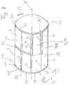
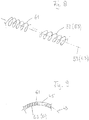
- a pressure and/or vacuum filter device 1 comprises: a filter drum 3, which defines a filter drum longitudinal-axis 5 (defining a filter drum longitudinal-direction) and which comprises a filter drum circumferential-wall 7 which extends around the filter drum longitudinal-axis 5, a filter medium 9, which is arranged on an outer side 11 of the filter drum circumferential-wall 7, and a plurality of fixation devices 13 (see, e.g., Fig. 3 ), by means of which the filter medium 9 is fixedly attached to the filter drum circumferential-wall 7, wherein the filter medium 9 comprises a plurality of filter medium pieces 9 which are separate from each other and which respectively (e.g.
- each) are made (e.g., at least for the most part seamless) of a filter cloth material und which respectively (e.g., each) have filter medium piece longitudinal-edges 15, which are arranged opposite (in direction transverse to the filter drum longitudinal-axis 5) to each other and which are at least for the most part a non-patched and/or seamless part of the (corresponding) filter cloth material and/or of the (corresponding) filter medium piece 9, as well as filter medium piece transverse-edges 17 which are arranged opposite (in filter drum longitudinal-direction) to each other and which at least for the most part are a non-patched and/or seamless component of the (corresponding) filter cloth material and/or filter medium-piece 9, and which (filter medium pieces 9) extend with their filter medium piece longitudinal-edges 15 parallel to the filter drum longitudinal axis 5 as well as in a manner to be adjacent to each other, thereby forming an at least for the most part complete (e.g., closed) filter medium surface 19, wherein the plurality of fixation devices 13 comprises/comprise
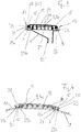
- the plurality of fixation devices 13 further comprises/comprise a plurality of elongated longitudinal-edge holding bodies 37 which respectively define a longitudinal-edge holding body longitudinal-axis 39 and which are received in a respectively assigned longitudinal-edge receiving groove 21 (of the longitudinal-edge receiving grooves 21) and which extend with their longitudinal-edge holding body longitudinal-axis 39 parallel to the longitudinal-edge receiving groove longitudinal-axis 23 of the corresponding longitudinal-edge receiving groove 21 and which respectively (e.g., each) have a longitudinal-edge holding body cross-sectional diameter d which is larger than a width of the longitudinal-edge receiving groove access opening 25 of the corresponding longitudinal-edge receiving groove 21 to thereby hold the respective filter medium piece longitudinal edge 15 together with its flat ribbon shaped filter medium longitudinal-edge reinforcement 31 in the respectively assigned undercut 29a, 29b.
- the respective transverse-edge receiving groove 45 may be formed correspondingly to the (respective) longitudinal-edge receiving groove (so that in this regard, it is referred to Figs. 5-7d , in which the features of the transverse-edge receiving groove 45 are identified by references signs which are put in parentheses) and may therefore be formed, with respect to the transverse-edge receiving groove longitudinal axis 45, on both sides with a respective elongated undercut 47a, 47n which extends along the transverse-edge receiving groove longitudinal-axis 43 and which is assigned to a respective filter medium piece transverse-edge 17, wherein the respective filter medium piece transverse-edge 17 is, at least for the most part continuously, provided with a filter medium transverse-edge reinforcement 49 which is flat ribbon shaped and which is arranged adjacently to a front face 51 of the filter medium piece transverse-edge 17 and on the filter medium piece transverse edge 17 and is patched to the filter medium piece transverse edge 17, in this case, e.g., is fixed to the filter medium piece transverse-
- transverse-edge holding body longitudinal axis 55 which respectively (e.g., each) define a transverse-edge holding body longitudinal axis 55 and which are received in a respectively assigned transverse-edge receiving groove 41 and extend with their transverse-edge holding body longitudinal-axis 55 parallel to the transverse-edge receiving groove longitudinal-axis 43 of the corresponding transverse-edge receiving groove 41 and which respectively (e.g., each) have a transverse-edge receiving body cross-sectional diameter d which is larger than a width b of the transverse-edge receiving groove access opening 45 of the corresponding transverse-edge receiving groove 41 to thereby hold the respective filter medium piece transverse-edge 17 together with its flat ribbon shaped filter medium transverse-edge reinforcement 49 in the respectively assigned undercut 47a, 47b.
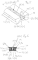
- Figs. 8 and 9 show a holding body which can be used as longitudinal-edge holding body 37 or (as well as) as transverse-edge holding body 53 und which is formed by a helix-structure 61 of, e.g., a wire, which (helix structure 61) has a helix-structure cross-section transverse to the longitudinal-edge/transverse-edge holding body longitudinal-axis 37, 43 and which helix-structure 61 is angular flexible with respect to the longitudinal-edge/transverse-edge holding body longitudinal-axis 39, 43 and is rigid in radial direction of its helix-structure cross-section.
- a helix-structure 61 of, e.g., a wire, which (helix structure 61) has a helix-structure cross-section transverse to the longitudinal-edge/transverse-edge holding body longitudinal-axis 37, 43 and which helix-structure 61 is angular flexible with respect to the longitudinal-edge/transverse-edge holding body longitudinal-axis 39
- the helix-structure 61 can be longitudinally inserted into the transverse-edge receiving groove 45, which extends in circumferential direction of the filter drum 3, and can, because of its angular flexibility, easily follow the curvature of the transverse-edge receiving groove 45 (cf. Fig. 9 ), wherein, however, because of its rigid cross-section and/or because of the radial rigidity of the individual turns, e.g.
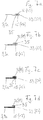
- Figures 7a to 7d respectively show, in a cross-section, filter medium longitudinal-edge reinforcements 33 and/or filter medium transverse-edge reinforcements 41 according to diverse embodiments of the invention.
- Figs. 7a and 7 there are one or more of the filter medium longitudinal-edge reinforcements 31 or is the respective filter medium longitudinal-edge reinforcement 31 and/or are one or more of the filter medium transverse-edge reinforcements 49 or is the respective filter medium transverse-edge reinforcement 49 formed by the filter cloth material of the corresponding filter medium piece 9a and formed as a hem (e.g. tuck) which is formed by one-time ( Fig. 7a ) or by multiple-times ( Fig. 7b ) inwardly folding of the filter cloth material along the corresponding filter medium piece longitudinal-edge 16 or along the corresponding filter medium piece transverse-edge 17, respectively.
- a hem e.g. tuck
- the filter medium longitudinal-edge reinforcement 31 and/or the filter medium transverse-edge reinforcement 49 is/are, e.g., formed as a non-folded reinforcement ribbon.
- the respective ribbon-shaped filter medium longitudinal-edge reinforcement 31 and/or the respective filter medium transverse-edge reinforcement 49 is elongated and extends with its longitudinal-axis along the respectively assigned filter medium longitudinal edge receiving groove 21 and/or filter medium transverse-edge receiving groove 41, respectively.
- the respective filter medium longitudinal-edge reinforcement 31 and/or the respective filter medium transverse-edge reinforcement 49 is arranged, with respect to the filter drum longitudinal-axis 5, on a radial inner side 71 of the corresponding filter medium piece 9a.
- the longitudinal-edge receiving grooves 21 are, e.g., formed in respectively assigned separation ledges 73 which are formed and/or are arranged on the outer side 11 of the filter drum 3 (and on the filter drum 3) and which extend along and/or parallel to the filter drum longitudinal-axis 5.
- the transverse-edge receiving grooves 41 are, e.g., formed in respectively assigned ring ledges 75 which extend around the outer circumference of the filter drum 3 in an encircling manner and which, e.g., are arranged at a respective axial end portion of the filter drum 3 (see, e.g., Figs. 1 and 2 ).
- the cross-section of the respective ring ledge 75 may, e.g., be formed in the same shape as the cross-cross section of the separation ledge 73 or may be formed similar thereto (cf., e.g., separation ledge cross-sections of Figs. 3-6 ).
- an additional ring ledge 77 is provided on the filter drum 3, in which, however, no transverse-edge receiving groove is formed, but which is, without interruption and/or continuously, superposed (along the filter drum longitudinal-axis 5) by a respective filter medium piece 9a.
- the separation ledges 73 are spaced, e.g. by regular distances, from each other in circumferential direction 27 of the filter drum 3, and the ring ledges 75 are spaced from each other in filter drum longitudinal-direction (along the filter drum longitudinal-axis 5).
- the separation ledges 73 and the ring ledges 75 delimit respective filter cells 79 which, e.g., respectively (e.g. each) comprise a respectively assigned filter cell insertion part 81 which is arranged between the outer side 11 of the filter drum 3 and the respectively assigned filter medium piece 9a and which forms a drainage space for the liquid separated from the suspension in connection with the filtering process, and a funnel-shaped collecting portion 83, to which a conduit (e.g. a tube) 85 is connected for discharging the separated liquid out of the filter cell 79 as well as out of the filter drum 3.
- a conduit e.g. a tube
- the conduits 85 are guided within the interior of the filter drum 3 to the front end of the filter drum 3 to a control head 87 which is arranged on said front end of the filter drum 3, via which (control head 87) the conduits 85 are connected to schematically shown discharge lines 89.
- the filter drum 3 is further connected to a central drive shaft 91 of the pressure and/or vacuum filter device 1, which (drive shaft 91) is itself connected to a drive motor M for rotationally driving the filter drum 3 about its filter drum longitudinal-axis 5.
Landscapes
- Chemical & Material Sciences (AREA)
- Chemical Kinetics & Catalysis (AREA)
- Filtration Of Liquid (AREA)
Applications Claiming Priority (1)
| Application Number | Priority Date | Filing Date | Title |
|---|---|---|---|
| DE102016111842.7A DE102016111842A1 (de) | 2016-06-28 | 2016-06-28 | Druck- und/oder Vakuumfiltervorrichtung |
Publications (2)
| Publication Number | Publication Date |
|---|---|
| EP3263204A1 true EP3263204A1 (de) | 2018-01-03 |
| EP3263204B1 EP3263204B1 (de) | 2018-09-19 |
Family
ID=59337434
Family Applications (1)
| Application Number | Title | Priority Date | Filing Date |
|---|---|---|---|
| EP17178026.5A Active EP3263204B1 (de) | 2016-06-28 | 2017-06-27 | Druck- und/oder vakuumfiltervorrichtung |
Country Status (2)
| Country | Link |
|---|---|
| EP (1) | EP3263204B1 (de) |
| DE (1) | DE102016111842A1 (de) |
Cited By (2)
| Publication number | Priority date | Publication date | Assignee | Title |
|---|---|---|---|---|
| CN116236879A (zh) * | 2023-03-20 | 2023-06-09 | 北京绿纪元环境科技有限责任公司 | 一种城市voc废气处理系统及方法 |
| WO2025133536A1 (fr) * | 2023-12-21 | 2025-06-26 | Faivre Group | Tambour pour un filtre a tambour |
Families Citing this family (1)
| Publication number | Priority date | Publication date | Assignee | Title |
|---|---|---|---|---|
| DE102018130204A1 (de) | 2018-11-28 | 2020-05-28 | Andritz Kmpt Gmbh | Filtrationsvorrichtung |
Citations (6)
| Publication number | Priority date | Publication date | Assignee | Title |
|---|---|---|---|---|
| US2018398A (en) * | 1935-01-04 | 1935-10-22 | Oliver United Filters Inc | Clamp |
| US2567266A (en) * | 1947-06-04 | 1951-09-11 | Frank W Young | Filter |
| US3036354A (en) * | 1960-04-29 | 1962-05-29 | Dorr Oliver Inc | Clamp |
| JPS54108976A (en) * | 1978-02-14 | 1979-08-27 | Mitsubishi Kakoki Kk | Method of mounting filter cloth in vacuum rotary filter |
| WO1994000218A1 (en) * | 1992-06-24 | 1994-01-06 | Královopolská, A.S. | Filter drum |
| US20070251873A1 (en) * | 2003-11-27 | 2007-11-01 | Madison Filter 981 Ltd. | Filter Cloth Retention |
Family Cites Families (2)
| Publication number | Priority date | Publication date | Assignee | Title |
|---|---|---|---|---|
| DE922226C (de) * | 1953-05-19 | 1955-01-10 | Erich Fest | Drehfilter fuer Betrieb mittels Unter- oder UEberdruck oder beider zugleich |
| DE4200304A1 (de) * | 1992-01-09 | 1993-07-15 | Dorr Oliver Inc | Siebeinrichtung |
-
2016
- 2016-06-28 DE DE102016111842.7A patent/DE102016111842A1/de not_active Ceased
-
2017
- 2017-06-27 EP EP17178026.5A patent/EP3263204B1/de active Active
Patent Citations (6)
| Publication number | Priority date | Publication date | Assignee | Title |
|---|---|---|---|---|
| US2018398A (en) * | 1935-01-04 | 1935-10-22 | Oliver United Filters Inc | Clamp |
| US2567266A (en) * | 1947-06-04 | 1951-09-11 | Frank W Young | Filter |
| US3036354A (en) * | 1960-04-29 | 1962-05-29 | Dorr Oliver Inc | Clamp |
| JPS54108976A (en) * | 1978-02-14 | 1979-08-27 | Mitsubishi Kakoki Kk | Method of mounting filter cloth in vacuum rotary filter |
| WO1994000218A1 (en) * | 1992-06-24 | 1994-01-06 | Královopolská, A.S. | Filter drum |
| US20070251873A1 (en) * | 2003-11-27 | 2007-11-01 | Madison Filter 981 Ltd. | Filter Cloth Retention |
Cited By (3)
| Publication number | Priority date | Publication date | Assignee | Title |
|---|---|---|---|---|
| CN116236879A (zh) * | 2023-03-20 | 2023-06-09 | 北京绿纪元环境科技有限责任公司 | 一种城市voc废气处理系统及方法 |
| WO2025133536A1 (fr) * | 2023-12-21 | 2025-06-26 | Faivre Group | Tambour pour un filtre a tambour |
| FR3157216A1 (fr) * | 2023-12-21 | 2025-06-27 | Faivre Group | Tambour pour un filtre à tambour |
Also Published As
| Publication number | Publication date |
|---|---|
| DE102016111842A1 (de) | 2017-12-28 |
| EP3263204B1 (de) | 2018-09-19 |
Similar Documents
| Publication | Publication Date | Title |
|---|---|---|
| EP3263204B1 (de) | Druck- und/oder vakuumfiltervorrichtung | |
| US11547960B2 (en) | Filter arrangement with support core and methods | |
| AU2004200262B2 (en) | Well completion method and apparatus | |
| US8075720B2 (en) | Circumferentially pleated filter assembly and method of forming the same | |
| KR20190121314A (ko) | 필터 장치 | |
| DE102014003153A1 (de) | Katheter zum gerichteten Leiten eines Fluids, insbesondere einer Körperflüssigkeit | |
| AU2010295359B2 (en) | A filter | |
| EP3452203B1 (de) | Ringförmiges filterelement, insbesondere zur gasfiltration | |
| EP1134015A3 (de) | Filter mit hohem Massendurchfluss | |
| JP2013039557A (ja) | プリーツフィルターカートリッジと共に使用するためのフィルターコア | |
| US20130255204A1 (en) | Expandable cage for baghouse filter | |
| US10661203B2 (en) | Enhanced liquid filter bag | |
| CN102233219A (zh) | 用于高温打摺过滤器的螺旋式扎条带方法 | |
| EP2409749A1 (de) | Kernlose Filterpatrone und Verfahren zur Herstellung einer kernlosen Filterpatrone | |
| DE102009046781A1 (de) | Wärmetauscheranordnung, insbesondere für ein Fahrzeugheizgerät | |
| EP1741478B1 (de) | Filterelement | |
| EP4342568A3 (de) | Gekrümmter kern für filter mit variabler faltenbildung | |
| FI74595C (fi) | Veckat slanghoelje, i synnerhet korvhoelje samt veckorgan och anordning foer dess framstaellning. | |
| US5207856A (en) | Apparatus for making a filter support tube | |
| US20250195867A1 (en) | Blood pump motor | |
| DE202008009426U1 (de) | Filter | |
| US20230405507A1 (en) | Corrugated helical shaped filter media | |
| DE2709683C3 (de) | Scheibenfilter | |
| DE102006059222A1 (de) | Verfahren zum Herstellen einer Filterkerze mit metallischem Filtersieb und Filterkerze hiermit | |
| DE10216735A1 (de) | Schubbeutelzentrifuge (Abdichtung des Trommeldeckels) |
Legal Events
| Date | Code | Title | Description |
|---|---|---|---|
| PUAI | Public reference made under article 153(3) epc to a published international application that has entered the european phase |
Free format text: ORIGINAL CODE: 0009012 |
|
| STAA | Information on the status of an ep patent application or granted ep patent |
Free format text: STATUS: REQUEST FOR EXAMINATION WAS MADE |
|
| 17P | Request for examination filed |
Effective date: 20170627 |
|
| AK | Designated contracting states |
Kind code of ref document: A1 Designated state(s): AL AT BE BG CH CY CZ DE DK EE ES FI FR GB GR HR HU IE IS IT LI LT LU LV MC MK MT NL NO PL PT RO RS SE SI SK SM TR |
|
| AX | Request for extension of the european patent |
Extension state: BA ME |
|
| RBV | Designated contracting states (corrected) |
Designated state(s): AL AT BE BG CH CY CZ DE DK EE ES FI FR GB GR HR HU IE IS IT LI LT LU LV MC MK MT NL NO PL PT RO RS SE SI SK SM TR |
|
| RIC1 | Information provided on ipc code assigned before grant |
Ipc: B01D 33/067 20060101AFI20180226BHEP Ipc: B01D 33/073 20060101ALI20180226BHEP |
|
| GRAP | Despatch of communication of intention to grant a patent |
Free format text: ORIGINAL CODE: EPIDOSNIGR1 |
|
| STAA | Information on the status of an ep patent application or granted ep patent |
Free format text: STATUS: GRANT OF PATENT IS INTENDED |
|
| INTG | Intention to grant announced |
Effective date: 20180409 |
|
| GRAS | Grant fee paid |
Free format text: ORIGINAL CODE: EPIDOSNIGR3 |
|
| GRAA | (expected) grant |
Free format text: ORIGINAL CODE: 0009210 |
|
| STAA | Information on the status of an ep patent application or granted ep patent |
Free format text: STATUS: THE PATENT HAS BEEN GRANTED |
|
| AK | Designated contracting states |
Kind code of ref document: B1 Designated state(s): AL AT BE BG CH CY CZ DE DK EE ES FI FR GB GR HR HU IE IS IT LI LT LU LV MC MK MT NL NO PL PT RO RS SE SI SK SM TR |
|
| REG | Reference to a national code |
Ref country code: GB Ref legal event code: FG4D |
|
| REG | Reference to a national code |
Ref country code: CH Ref legal event code: EP |
|
| REG | Reference to a national code |
Ref country code: AT Ref legal event code: REF Ref document number: 1042572 Country of ref document: AT Kind code of ref document: T Effective date: 20181015 |
|
| REG | Reference to a national code |
Ref country code: IE Ref legal event code: FG4D |
|
| REG | Reference to a national code |
Ref country code: DE Ref legal event code: R096 Ref document number: 602017000441 Country of ref document: DE |
|
| REG | Reference to a national code |
Ref country code: NL Ref legal event code: MP Effective date: 20180919 |
|
| PG25 | Lapsed in a contracting state [announced via postgrant information from national office to epo] |
Ref country code: NO Free format text: LAPSE BECAUSE OF FAILURE TO SUBMIT A TRANSLATION OF THE DESCRIPTION OR TO PAY THE FEE WITHIN THE PRESCRIBED TIME-LIMIT Effective date: 20181219 Ref country code: FI Free format text: LAPSE BECAUSE OF FAILURE TO SUBMIT A TRANSLATION OF THE DESCRIPTION OR TO PAY THE FEE WITHIN THE PRESCRIBED TIME-LIMIT Effective date: 20180919 Ref country code: GR Free format text: LAPSE BECAUSE OF FAILURE TO SUBMIT A TRANSLATION OF THE DESCRIPTION OR TO PAY THE FEE WITHIN THE PRESCRIBED TIME-LIMIT Effective date: 20181220 Ref country code: LT Free format text: LAPSE BECAUSE OF FAILURE TO SUBMIT A TRANSLATION OF THE DESCRIPTION OR TO PAY THE FEE WITHIN THE PRESCRIBED TIME-LIMIT Effective date: 20180919 Ref country code: RS Free format text: LAPSE BECAUSE OF FAILURE TO SUBMIT A TRANSLATION OF THE DESCRIPTION OR TO PAY THE FEE WITHIN THE PRESCRIBED TIME-LIMIT Effective date: 20180919 Ref country code: SE Free format text: LAPSE BECAUSE OF FAILURE TO SUBMIT A TRANSLATION OF THE DESCRIPTION OR TO PAY THE FEE WITHIN THE PRESCRIBED TIME-LIMIT Effective date: 20180919 Ref country code: BG Free format text: LAPSE BECAUSE OF FAILURE TO SUBMIT A TRANSLATION OF THE DESCRIPTION OR TO PAY THE FEE WITHIN THE PRESCRIBED TIME-LIMIT Effective date: 20181219 |
|
| REG | Reference to a national code |
Ref country code: LT Ref legal event code: MG4D |
|
| PG25 | Lapsed in a contracting state [announced via postgrant information from national office to epo] |
Ref country code: HR Free format text: LAPSE BECAUSE OF FAILURE TO SUBMIT A TRANSLATION OF THE DESCRIPTION OR TO PAY THE FEE WITHIN THE PRESCRIBED TIME-LIMIT Effective date: 20180919 Ref country code: LV Free format text: LAPSE BECAUSE OF FAILURE TO SUBMIT A TRANSLATION OF THE DESCRIPTION OR TO PAY THE FEE WITHIN THE PRESCRIBED TIME-LIMIT Effective date: 20180919 Ref country code: AL Free format text: LAPSE BECAUSE OF FAILURE TO SUBMIT A TRANSLATION OF THE DESCRIPTION OR TO PAY THE FEE WITHIN THE PRESCRIBED TIME-LIMIT Effective date: 20180919 |
|
| REG | Reference to a national code |
Ref country code: AT Ref legal event code: MK05 Ref document number: 1042572 Country of ref document: AT Kind code of ref document: T Effective date: 20180919 |
|
| PG25 | Lapsed in a contracting state [announced via postgrant information from national office to epo] |
Ref country code: PL Free format text: LAPSE BECAUSE OF FAILURE TO SUBMIT A TRANSLATION OF THE DESCRIPTION OR TO PAY THE FEE WITHIN THE PRESCRIBED TIME-LIMIT Effective date: 20180919 Ref country code: EE Free format text: LAPSE BECAUSE OF FAILURE TO SUBMIT A TRANSLATION OF THE DESCRIPTION OR TO PAY THE FEE WITHIN THE PRESCRIBED TIME-LIMIT Effective date: 20180919 Ref country code: NL Free format text: LAPSE BECAUSE OF FAILURE TO SUBMIT A TRANSLATION OF THE DESCRIPTION OR TO PAY THE FEE WITHIN THE PRESCRIBED TIME-LIMIT Effective date: 20180919 Ref country code: RO Free format text: LAPSE BECAUSE OF FAILURE TO SUBMIT A TRANSLATION OF THE DESCRIPTION OR TO PAY THE FEE WITHIN THE PRESCRIBED TIME-LIMIT Effective date: 20180919 Ref country code: ES Free format text: LAPSE BECAUSE OF FAILURE TO SUBMIT A TRANSLATION OF THE DESCRIPTION OR TO PAY THE FEE WITHIN THE PRESCRIBED TIME-LIMIT Effective date: 20180919 Ref country code: CZ Free format text: LAPSE BECAUSE OF FAILURE TO SUBMIT A TRANSLATION OF THE DESCRIPTION OR TO PAY THE FEE WITHIN THE PRESCRIBED TIME-LIMIT Effective date: 20180919 Ref country code: IS Free format text: LAPSE BECAUSE OF FAILURE TO SUBMIT A TRANSLATION OF THE DESCRIPTION OR TO PAY THE FEE WITHIN THE PRESCRIBED TIME-LIMIT Effective date: 20190119 Ref country code: AT Free format text: LAPSE BECAUSE OF FAILURE TO SUBMIT A TRANSLATION OF THE DESCRIPTION OR TO PAY THE FEE WITHIN THE PRESCRIBED TIME-LIMIT Effective date: 20180919 |
|
| PG25 | Lapsed in a contracting state [announced via postgrant information from national office to epo] |
Ref country code: SK Free format text: LAPSE BECAUSE OF FAILURE TO SUBMIT A TRANSLATION OF THE DESCRIPTION OR TO PAY THE FEE WITHIN THE PRESCRIBED TIME-LIMIT Effective date: 20180919 Ref country code: SM Free format text: LAPSE BECAUSE OF FAILURE TO SUBMIT A TRANSLATION OF THE DESCRIPTION OR TO PAY THE FEE WITHIN THE PRESCRIBED TIME-LIMIT Effective date: 20180919 Ref country code: PT Free format text: LAPSE BECAUSE OF FAILURE TO SUBMIT A TRANSLATION OF THE DESCRIPTION OR TO PAY THE FEE WITHIN THE PRESCRIBED TIME-LIMIT Effective date: 20190119 |
|
| REG | Reference to a national code |
Ref country code: DE Ref legal event code: R097 Ref document number: 602017000441 Country of ref document: DE |
|
| PLBE | No opposition filed within time limit |
Free format text: ORIGINAL CODE: 0009261 |
|
| STAA | Information on the status of an ep patent application or granted ep patent |
Free format text: STATUS: NO OPPOSITION FILED WITHIN TIME LIMIT |
|
| PG25 | Lapsed in a contracting state [announced via postgrant information from national office to epo] |
Ref country code: DK Free format text: LAPSE BECAUSE OF FAILURE TO SUBMIT A TRANSLATION OF THE DESCRIPTION OR TO PAY THE FEE WITHIN THE PRESCRIBED TIME-LIMIT Effective date: 20180919 |
|
| 26N | No opposition filed |
Effective date: 20190620 |
|
| PG25 | Lapsed in a contracting state [announced via postgrant information from national office to epo] |
Ref country code: MC Free format text: LAPSE BECAUSE OF FAILURE TO SUBMIT A TRANSLATION OF THE DESCRIPTION OR TO PAY THE FEE WITHIN THE PRESCRIBED TIME-LIMIT Effective date: 20180919 |
|
| PG25 | Lapsed in a contracting state [announced via postgrant information from national office to epo] |
Ref country code: IE Free format text: LAPSE BECAUSE OF NON-PAYMENT OF DUE FEES Effective date: 20190627 |
|
| PG25 | Lapsed in a contracting state [announced via postgrant information from national office to epo] |
Ref country code: LU Free format text: LAPSE BECAUSE OF NON-PAYMENT OF DUE FEES Effective date: 20190627 |
|
| REG | Reference to a national code |
Ref country code: CH Ref legal event code: PL |
|
| PG25 | Lapsed in a contracting state [announced via postgrant information from national office to epo] |
Ref country code: CH Free format text: LAPSE BECAUSE OF NON-PAYMENT OF DUE FEES Effective date: 20200630 Ref country code: LI Free format text: LAPSE BECAUSE OF NON-PAYMENT OF DUE FEES Effective date: 20200630 |
|
| PG25 | Lapsed in a contracting state [announced via postgrant information from national office to epo] |
Ref country code: CY Free format text: LAPSE BECAUSE OF FAILURE TO SUBMIT A TRANSLATION OF THE DESCRIPTION OR TO PAY THE FEE WITHIN THE PRESCRIBED TIME-LIMIT Effective date: 20180919 |
|
| PG25 | Lapsed in a contracting state [announced via postgrant information from national office to epo] |
Ref country code: HU Free format text: LAPSE BECAUSE OF FAILURE TO SUBMIT A TRANSLATION OF THE DESCRIPTION OR TO PAY THE FEE WITHIN THE PRESCRIBED TIME-LIMIT; INVALID AB INITIO Effective date: 20170627 Ref country code: MT Free format text: LAPSE BECAUSE OF FAILURE TO SUBMIT A TRANSLATION OF THE DESCRIPTION OR TO PAY THE FEE WITHIN THE PRESCRIBED TIME-LIMIT Effective date: 20180919 |
|
| PG25 | Lapsed in a contracting state [announced via postgrant information from national office to epo] |
Ref country code: SI Free format text: LAPSE BECAUSE OF FAILURE TO SUBMIT A TRANSLATION OF THE DESCRIPTION OR TO PAY THE FEE WITHIN THE PRESCRIBED TIME-LIMIT Effective date: 20180919 |
|
| GBPC | Gb: european patent ceased through non-payment of renewal fee |
Effective date: 20210627 |
|
| PG25 | Lapsed in a contracting state [announced via postgrant information from national office to epo] |
Ref country code: GB Free format text: LAPSE BECAUSE OF NON-PAYMENT OF DUE FEES Effective date: 20210627 |
|
| PG25 | Lapsed in a contracting state [announced via postgrant information from national office to epo] |
Ref country code: MK Free format text: LAPSE BECAUSE OF FAILURE TO SUBMIT A TRANSLATION OF THE DESCRIPTION OR TO PAY THE FEE WITHIN THE PRESCRIBED TIME-LIMIT Effective date: 20180919 |
|
| PGFP | Annual fee paid to national office [announced via postgrant information from national office to epo] |
Ref country code: DE Payment date: 20240516 Year of fee payment: 8 |
|
| PGFP | Annual fee paid to national office [announced via postgrant information from national office to epo] |
Ref country code: FR Payment date: 20240621 Year of fee payment: 8 |
|
| PGFP | Annual fee paid to national office [announced via postgrant information from national office to epo] |
Ref country code: TR Payment date: 20240621 Year of fee payment: 8 Ref country code: BE Payment date: 20240618 Year of fee payment: 8 |
|
| PGFP | Annual fee paid to national office [announced via postgrant information from national office to epo] |
Ref country code: IT Payment date: 20240628 Year of fee payment: 8 |
|
| REG | Reference to a national code |
Ref country code: DE Ref legal event code: R119 Ref document number: 602017000441 Country of ref document: DE |
|
| REG | Reference to a national code |
Ref country code: BE Ref legal event code: MM Effective date: 20250630 |
|
| PG25 | Lapsed in a contracting state [announced via postgrant information from national office to epo] |
Ref country code: DE Free format text: LAPSE BECAUSE OF NON-PAYMENT OF DUE FEES Effective date: 20260101 |
|
| PG25 | Lapsed in a contracting state [announced via postgrant information from national office to epo] |
Ref country code: BE Free format text: LAPSE BECAUSE OF NON-PAYMENT OF DUE FEES Effective date: 20250630 Ref country code: IT Free format text: LAPSE BECAUSE OF NON-PAYMENT OF DUE FEES Effective date: 20250627 |
|
| PG25 | Lapsed in a contracting state [announced via postgrant information from national office to epo] |
Ref country code: FR Free format text: LAPSE BECAUSE OF NON-PAYMENT OF DUE FEES Effective date: 20250630 |