EP3263232A1 - Sorting or classifying machines - Google Patents
Sorting or classifying machines Download PDFInfo
- Publication number
- EP3263232A1 EP3263232A1 EP16176664.7A EP16176664A EP3263232A1 EP 3263232 A1 EP3263232 A1 EP 3263232A1 EP 16176664 A EP16176664 A EP 16176664A EP 3263232 A1 EP3263232 A1 EP 3263232A1
- Authority
- EP
- European Patent Office
- Prior art keywords
- chute
- housing
- machine
- pivot
- sorting
- Prior art date
- Legal status (The legal status is an assumption and is not a legal conclusion. Google has not performed a legal analysis and makes no representation as to the accuracy of the status listed.)
- Withdrawn
Links
Images


Classifications
-
- B—PERFORMING OPERATIONS; TRANSPORTING
- B07—SEPARATING SOLIDS FROM SOLIDS; SORTING
- B07C—POSTAL SORTING; SORTING INDIVIDUAL ARTICLES, OR BULK MATERIAL FIT TO BE SORTED PIECE-MEAL, e.g. BY PICKING
- B07C5/00—Sorting according to a characteristic or feature of the articles or material being sorted, e.g. by control effected by devices which detect or measure such characteristic or feature; Sorting by manually actuated devices, e.g. switches
- B07C5/02—Measures preceding sorting, e.g. arranging articles in a stream orientating
-
- B—PERFORMING OPERATIONS; TRANSPORTING
- B07—SEPARATING SOLIDS FROM SOLIDS; SORTING
- B07C—POSTAL SORTING; SORTING INDIVIDUAL ARTICLES, OR BULK MATERIAL FIT TO BE SORTED PIECE-MEAL, e.g. BY PICKING
- B07C5/00—Sorting according to a characteristic or feature of the articles or material being sorted, e.g. by control effected by devices which detect or measure such characteristic or feature; Sorting by manually actuated devices, e.g. switches
- B07C5/34—Sorting according to other particular properties
- B07C5/342—Sorting according to other particular properties according to optical properties, e.g. colour
-
- B—PERFORMING OPERATIONS; TRANSPORTING
- B07—SEPARATING SOLIDS FROM SOLIDS; SORTING
- B07C—POSTAL SORTING; SORTING INDIVIDUAL ARTICLES, OR BULK MATERIAL FIT TO BE SORTED PIECE-MEAL, e.g. BY PICKING
- B07C2501/00—Sorting according to a characteristic or feature of the articles or material to be sorted
- B07C2501/0081—Sorting of food items
Definitions
- the present invention relates to sorting or classifying machines for sorting or classifying product, in particular flows of particulate product, and especially foodstuffs and vegetables.
- the present invention provides a sorting or classifying machine for sorting or classifying product, comprising a housing which includes an internal region, and a chute which has a guide surface and is supported by the housing; characterized in that the chute is pivotably coupled to the housing about a first pivot between a first, operative configuration, in which the chute extends across the internal region and prevents access or entry into the internal region by an operator, and a second, stowed configuration, in which an operator can access or enter the internal region.
- the present invention provides a sorting or classifying machine for sorting or classifying product, comprising a housing which includes an internal region, and a chute which has a guide surface and is supported by the housing; characterized in that the chute is pivotably coupled to the housing about a first pivot between a first, operative configuration, in which the guide surface is inclined downwardly and guides product, and a second, stowed configuration, in which an operator can access the internal region.
- the present invention provides a sorting or classifying machine for sorting or classifying product, comprising a housing, and a chute which has a guide surface and is supported by the housing; characterized in that the chute comprises a first member which is pivotally coupled to the housing about a first pivot, and a second member which supports the guide surface and is pivotally coupled to the first member about a second pivot between an operative, expanded position and a collapsed position.
- the sorting or classifying machine comprises a housing 3, a chute 5 which is supported by the housing 3 and to which a flow of particulate product is delivered, typically from an infeed vibrator, at least one illumination unit 7a-d for illuminating product as delivered on and/or from the chute 5, and at least one detector 9a, b for detecting product as delivered on and/or from the chute 5.
- the housing 3 comprises a plurality of walls 17 which enclose an internal region 19.
- the housing 3 comprises side, end and upper walls 17.
- the housing 3 comprises a frame structure 21 and one or more panels 25, here at least one roof panel, which is attached to the frame structure 21, so as at least partially to enclose the housing 3.
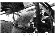
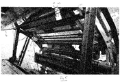
- the chute 5 comprises a guide surface 29 over which particulate product in use flows, and is pivotably coupled to the housing 3 about a first pivot 31, here provided by an axle, between a first, lowered, operative position (as illustrated in Figure 4 ), in which the guide surface 29 of the chute 5 is inclined downwardly and guides particulate product, and a second, stowed position (as illustrated in Figure 5 ), in which the chute 5 is disposed adjacent or at least partially within at least one of the walls 17 of the housing 3, here the upper wall 17.
- first pivot 31 is supported at the respective ends by mounting cradles 33.
- the present inventor has devised a configuration which advantageously allows for an operator more readily to access the internal region 19 of the housing 3, such as for cleaning or maintenance.
- the chute 5 is pivotally coupled to the first pivot 31 proximal a first, upper edge 35 of the chute 5, such that a major portion of the guide surface 29 is disposed to one side of the first pivot 31, and a second, distal edge 37 of the chute 5 depends in downward relation to the first edge 35 when the chute 5 is in the operative position.
- the housing 3 includes at least one engagement member 41, here a recess
- the chute 5 includes at least one engagement member 43, here a lug, which is counterpart to the at least one engagement member 41 on the housing 3, and the engagement members 41, 43 are configured to engage one another when the chute 5 is in the operative position and define a fixed, operative position for the second edge 37 of the chute 5.
- the housing 3 includes first and second engagement members 41
- the chute 5 includes first and second counterpart engagement members 43 in which respective ones of the first and second engagement members 41 of the housing 3 are located.
- the chute 5 includes a counterbalance 51 which is disposed to the opposite side of the pivot 31 to the major portion of the guide surface 29 of the chute 5, and acts to bias the chute 5 so as to maintain the chute 5 in the stowed position when the chute 5 is moved from the operative position.
- the counterbalance 51 could be replaced by an actuator, such as a pneumatic actuator, which is actuatable to move the chute 5 between the operative and stowed positions.
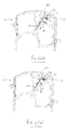
- the chute 5 comprises a first member 61 which is pivotally coupled to the first pivot 31, a second member 63 which supports the guide surface 29 and is pivotally coupled to the first member 61 about a second pivot 67, which is distal to the first pivot 31, here towards the second edge 37 of the chute 5, between an operative, expanded position (as illustrated in Figure 6(a) ) and a collapsed position (as illustrated in Figure 6(d) ), and a positioner 71 by which the position of second member 63 is adjustable between the operative and collapsed positions.
- the second member 63 is nested inwardly within the first member 61 when in the collapsed configuration.
- the positioner 71 comprises a cam member 73 and an actuator 75, here a handle, which is operated to move the cam member 73 between the expanded and collapsed positions.
- the chute 5 can be configured to have an expanded configuration for the guide surface 29 to receive particulate product, and allows for the chute 5 to be collapsed so as to adopt a smaller, compact configuration, which allows for the chute 5 to stowed adjacent the wall 17 of the housing 3 without requiring complicated articulation of the chute 5 to avoid collision with other component parts, such as the infeed vibrator.
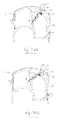
- Figures 6(a) to (d) and 7(a) to (d) illustrate, respectively, the steps in collapsing the chute members 61, 63, and stowing the collapsed chute 5 adjacent the upper wall 17 of the housing 3, with the counterbalance 51 maintaining the chute 5 in the stowed position.
Landscapes
- Sorting Of Articles (AREA)
Abstract
A sorting or classifying machine for sorting or classifying product, comprising a housing (3) which includes an internal region (19), and a chute (5) which has a guide surface (29) and is supported by the housing (3); characterized in that the chute (5) is pivotably coupled to the housing (3) about a first pivot (31) between a first, operative configuration, in which the chute (19) is extends across the internal region (19) and prevents access or entry into the internal region (19) by an operator, and a second, stowed position, in which an operator can access or enter the internal region (19).
Description
- The present invention relates to sorting or classifying machines for sorting or classifying product, in particular flows of particulate product, and especially foodstuffs and vegetables.
- In one aspect the present invention provides a sorting or classifying machine for sorting or classifying product, comprising a housing which includes an internal region, and a chute which has a guide surface and is supported by the housing; characterized in that the chute is pivotably coupled to the housing about a first pivot between a first, operative configuration, in which the chute extends across the internal region and prevents access or entry into the internal region by an operator, and a second, stowed configuration, in which an operator can access or enter the internal region.
- In another aspect the present invention provides a sorting or classifying machine for sorting or classifying product, comprising a housing which includes an internal region, and a chute which has a guide surface and is supported by the housing; characterized in that the chute is pivotably coupled to the housing about a first pivot between a first, operative configuration, in which the guide surface is inclined downwardly and guides product, and a second, stowed configuration, in which an operator can access the internal region.
- In a further aspect the present invention provides a sorting or classifying machine for sorting or classifying product, comprising a housing, and a chute which has a guide surface and is supported by the housing; characterized in that the chute comprises a first member which is pivotally coupled to the housing about a first pivot, and a second member which supports the guide surface and is pivotally coupled to the first member about a second pivot between an operative, expanded position and a collapsed position.
- Preferred embodiments of the present invention will now be described hereinbelow by way of example only with reference to the accompanying drawings, in which:
-
Figure 1 illustrates a perspective view of a sorting or classifying machine in accordance with one embodiment of the present invention; -
Figure 2 illustrates a side view of the sorting or classifying machine ofFigure 1 ; -
Figure 3 illustrates a vertical sectional view (along section I-I ofFigure 1 ) of the sorting or classifying machine ofFigure 1 ; -
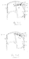
Figure 4 illustrates a fragmentary perspective view of the sorting or classifying machine ofFigure 1 , with the chute in the operative configuration; -
Figure 5 illustrates a fragmentary perspective view of the of the sorting or classifying machine ofFigure 1 , with the chute in the stowed configuration; -
Figures 6(a) to (d) illustrate the steps in collapsing the second chute part in relation to the first chute part of the sorting or classifying machine ofFigure 1 ; and -
Figures 7(a) to (d) illustrate the steps in stowing the chute of the sorting or classifying machine ofFigure 1 . - The sorting or classifying machine comprises a
housing 3, a chute 5 which is supported by thehousing 3 and to which a flow of particulate product is delivered, typically from an infeed vibrator, at least one illumination unit 7a-d for illuminating product as delivered on and/or from the chute 5, and at least one detector 9a, b for detecting product as delivered on and/or from the chute 5. - In this embodiment the
housing 3 comprises a plurality ofwalls 17 which enclose aninternal region 19. - In this embodiment the
housing 3 comprises side, end andupper walls 17. - In this embodiment the
housing 3 comprises aframe structure 21 and one ormore panels 25, here at least one roof panel, which is attached to theframe structure 21, so as at least partially to enclose thehousing 3. - In this embodiment the chute 5 comprises a
guide surface 29 over which particulate product in use flows, and is pivotably coupled to thehousing 3 about afirst pivot 31, here provided by an axle, between a first, lowered, operative position (as illustrated inFigure 4 ), in which theguide surface 29 of the chute 5 is inclined downwardly and guides particulate product, and a second, stowed position (as illustrated inFigure 5 ), in which the chute 5 is disposed adjacent or at least partially within at least one of thewalls 17 of thehousing 3, here theupper wall 17. - In this embodiment the
first pivot 31 is supported at the respective ends by mountingcradles 33. - By providing for stowing of the chute 5, the present inventor has devised a configuration which advantageously allows for an operator more readily to access the
internal region 19 of thehousing 3, such as for cleaning or maintenance. - In this embodiment the chute 5 is pivotally coupled to the
first pivot 31 proximal a first,upper edge 35 of the chute 5, such that a major portion of theguide surface 29 is disposed to one side of thefirst pivot 31, and a second,distal edge 37 of the chute 5 depends in downward relation to thefirst edge 35 when the chute 5 is in the operative position. - In one embodiment the
housing 3 includes at least one engagement member 41, here a recess, and the chute 5 includes at least oneengagement member 43, here a lug, which is counterpart to the at least one engagement member 41 on thehousing 3, and theengagement members 41, 43 are configured to engage one another when the chute 5 is in the operative position and define a fixed, operative position for thesecond edge 37 of the chute 5. - In this embodiment the
housing 3 includes first and second engagement members 41, and the chute 5 includes first and secondcounterpart engagement members 43 in which respective ones of the first and second engagement members 41 of thehousing 3 are located. - In this embodiment the chute 5 includes a
counterbalance 51 which is disposed to the opposite side of thepivot 31 to the major portion of theguide surface 29 of the chute 5, and acts to bias the chute 5 so as to maintain the chute 5 in the stowed position when the chute 5 is moved from the operative position. - In one alternative embodiment the
counterbalance 51 could be replaced by an actuator, such as a pneumatic actuator, which is actuatable to move the chute 5 between the operative and stowed positions. - In this embodiment the chute 5 comprises a
first member 61 which is pivotally coupled to thefirst pivot 31, asecond member 63 which supports theguide surface 29 and is pivotally coupled to thefirst member 61 about asecond pivot 67, which is distal to thefirst pivot 31, here towards thesecond edge 37 of the chute 5, between an operative, expanded position (as illustrated inFigure 6(a) ) and a collapsed position (as illustrated inFigure 6(d) ), and apositioner 71 by which the position ofsecond member 63 is adjustable between the operative and collapsed positions. - In this embodiment the
second member 63 is nested inwardly within thefirst member 61 when in the collapsed configuration. - In this embodiment the
positioner 71 comprises a cam member 73 and anactuator 75, here a handle, which is operated to move the cam member 73 between the expanded and collapsed positions. - With this configuration, the chute 5 can be configured to have an expanded configuration for the
guide surface 29 to receive particulate product, and allows for the chute 5 to be collapsed so as to adopt a smaller, compact configuration, which allows for the chute 5 to stowed adjacent thewall 17 of thehousing 3 without requiring complicated articulation of the chute 5 to avoid collision with other component parts, such as the infeed vibrator. -
Figures 6(a) to (d) and7(a) to (d) illustrate, respectively, the steps in collapsing thechute members upper wall 17 of thehousing 3, with thecounterbalance 51 maintaining the chute 5 in the stowed position. - Finally, it will be understood that the present invention has been described in its preferred embodiments and can be modified in many different ways without departing from the scope of the invention as defined by the appended claims.
Claims (15)
- A sorting or classifying machine for sorting or classifying product, comprising a housing (3) which includes an internal region (19), and a chute (5) which has a guide surface (29) and is supported by the housing (3); characterized in that the chute (5) is pivotably coupled to the housing (3) about a first pivot (31) between a first, operative configuration, in which the chute (19) extends across the internal region (19) and prevents access or entry into the internal region (19) by an operator, and a second, stowed configuration, in which an operator can access or enter the internal region (19).
- The machine of claim 1, wherein the chute (5) is disposed adjacent or at least partially within a wall of the housing (3).
- The machine of claim 2, wherein the wall (17) is an upper wall (17).
- The machine of any of claims 1 to 3, wherein the housing (3) comprises a plurality of walls (17) which enclose the internal region (19).
- The machine of any of claims 1 to 4, wherein the housing (3) comprises a frame structure (21) and one or more panels (25) which are attached to the frame structure (21) so as at least partially to enclose the housing (3), optionally the housing (3) comprises at least one roof panel (25).
- The machine of any of claims 1 to 5, wherein the first axis (31) comprises an axle which is supported by mounting cradles (33).
- The machine of any of claims 1 to 6, wherein the chute (5) is pivotally coupled to the first pivot (31) proximal a first edge (35) of the chute (5), such that a major portion of the guide surface (29) is disposed to one side of the first pivot (31), and a second, distal edge (37) of the chute (5) depends in downward relation to the first edge (35) when the chute (5) is in the operative position.
- The machine of claim 7, wherein the housing (3) includes at least one engagement member (41), and the chute (5) includes at least one engagement member (43), which is counterpart to the at least one engagement member (41) on the housing (3), and the engagement members (41, 43) are configured to engage one another when the chute (5) is in the operative position and define a fixed, operative position for the second edge (37) of the chute (5).
- The machine of claim 7 or 8, wherein the chute (5) includes a counterbalance (51) which is disposed to the opposite side of the first pivot (31) to the major portion of the guide surface (29), and acts to bias the chute (5) so as to maintain the chute (5) in the stowed position when the chute (5) is moved from the operative position.
- The machine of any of claims 7 to 9, wherein the chute (5) comprises a first member (61) which is pivotally coupled to the first pivot (31), and a second member (63) which supports the guide surface (29) and is pivotally coupled to the first member (61) about a second pivot (67), which is distal to the first pivot (31), between an operative, expanded position and a collapsed position.
- The machine of claim 10, wherein the second member (63) is nested within the first member (61) when in the collapsed configuration.
- The machine of claim 10 or 11, wherein the chute (5) further comprises a positioner (71) by which the position of second member (63) is adjustable between the operative and collapsed positions.
- The machine of claim 12, wherein the positioner (71) comprises a cam member (73) and an actuator 75, which is operated to move the cam member (73) between the expanded and collapsed positions.
- A sorting or classifying machine for sorting or classifying product, comprising a housing (3) which includes an internal region (19), and a chute (5) which has a guide surface (29) and is supported by the housing (3); characterized in that the chute (5) is pivotably coupled to the housing (3) about a first pivot (31) between a first, operative configuration, and a second, stowed configuration, in which an operator can access or enter the internal region (19).
- A sorting or classifying machine for sorting or classifying product, comprising a housing (3), and a chute (5) which has a guide surface (29) and is supported by the housing (3); characterized in that the chute (5) comprises a first member (61) which is pivotally coupled to the housing (3) about a first pivot (31), and a second member (63) which supports the guide surface (29) and is pivotally coupled to the first member (61) about a second pivot (67) between an operative, expanded position and a collapsed position.
Priority Applications (6)
| Application Number | Priority Date | Filing Date | Title |
|---|---|---|---|
| EP16176664.7A EP3263232A1 (en) | 2016-06-28 | 2016-06-28 | Sorting or classifying machines |
| ES17734062T ES2895387T3 (en) | 2016-06-28 | 2017-06-28 | Sorting or sorting machine |
| US16/313,596 US10888901B2 (en) | 2016-06-28 | 2017-06-28 | Sorting or classifying machines |
| EP17734062.7A EP3475001B1 (en) | 2016-06-28 | 2017-06-28 | Sorting or classifying machine |
| PCT/EP2017/066075 WO2018002190A1 (en) | 2016-06-28 | 2017-06-28 | Sorting or classifying machines |
| CL2018003829A CL2018003829A1 (en) | 2016-06-28 | 2018-12-27 | Sorting or sorting machines. |
Applications Claiming Priority (1)
| Application Number | Priority Date | Filing Date | Title |
|---|---|---|---|
| EP16176664.7A EP3263232A1 (en) | 2016-06-28 | 2016-06-28 | Sorting or classifying machines |
Publications (1)
| Publication Number | Publication Date |
|---|---|
| EP3263232A1 true EP3263232A1 (en) | 2018-01-03 |
Family
ID=56296560
Family Applications (2)
| Application Number | Title | Priority Date | Filing Date |
|---|---|---|---|
| EP16176664.7A Withdrawn EP3263232A1 (en) | 2016-06-28 | 2016-06-28 | Sorting or classifying machines |
| EP17734062.7A Active EP3475001B1 (en) | 2016-06-28 | 2017-06-28 | Sorting or classifying machine |
Family Applications After (1)
| Application Number | Title | Priority Date | Filing Date |
|---|---|---|---|
| EP17734062.7A Active EP3475001B1 (en) | 2016-06-28 | 2017-06-28 | Sorting or classifying machine |
Country Status (5)
| Country | Link |
|---|---|
| US (1) | US10888901B2 (en) |
| EP (2) | EP3263232A1 (en) |
| CL (1) | CL2018003829A1 (en) |
| ES (1) | ES2895387T3 (en) |
| WO (1) | WO2018002190A1 (en) |
Families Citing this family (1)
| Publication number | Priority date | Publication date | Assignee | Title |
|---|---|---|---|---|
| US11663923B2 (en) * | 2018-11-30 | 2023-05-30 | International Business Machines Corporation | Screening material waste |
Citations (2)
| Publication number | Priority date | Publication date | Assignee | Title |
|---|---|---|---|---|
| EP0325558A1 (en) * | 1988-01-07 | 1989-07-26 | Vetropack Ag | Method and device for detecting foreign matter in a stream of bodies pervious to electromagnetic radiation |
| US20080078707A1 (en) * | 2006-09-28 | 2008-04-03 | Wattawa Kim T | Modular system and apparatus for processing recyclable materials, and method of using same |
Family Cites Families (1)
| Publication number | Priority date | Publication date | Assignee | Title |
|---|---|---|---|---|
| US9067245B2 (en) * | 2013-03-08 | 2015-06-30 | Gerald Hubbell | Waste collection system |
-
2016
- 2016-06-28 EP EP16176664.7A patent/EP3263232A1/en not_active Withdrawn
-
2017
- 2017-06-28 WO PCT/EP2017/066075 patent/WO2018002190A1/en not_active Ceased
- 2017-06-28 US US16/313,596 patent/US10888901B2/en active Active
- 2017-06-28 EP EP17734062.7A patent/EP3475001B1/en active Active
- 2017-06-28 ES ES17734062T patent/ES2895387T3/en active Active
-
2018
- 2018-12-27 CL CL2018003829A patent/CL2018003829A1/en unknown
Patent Citations (2)
| Publication number | Priority date | Publication date | Assignee | Title |
|---|---|---|---|---|
| EP0325558A1 (en) * | 1988-01-07 | 1989-07-26 | Vetropack Ag | Method and device for detecting foreign matter in a stream of bodies pervious to electromagnetic radiation |
| US20080078707A1 (en) * | 2006-09-28 | 2008-04-03 | Wattawa Kim T | Modular system and apparatus for processing recyclable materials, and method of using same |
Also Published As
| Publication number | Publication date |
|---|---|
| US20190314862A1 (en) | 2019-10-17 |
| EP3475001B1 (en) | 2021-08-04 |
| US10888901B2 (en) | 2021-01-12 |
| EP3475001A1 (en) | 2019-05-01 |
| ES2895387T3 (en) | 2022-02-21 |
| CL2018003829A1 (en) | 2019-03-22 |
| WO2018002190A1 (en) | 2018-01-04 |
Similar Documents
| Publication | Publication Date | Title |
|---|---|---|
| US7357269B2 (en) | Container | |
| CN107282809B (en) | Production line for U-shaped large coaming of refrigerator liner | |
| US5238300A (en) | Retractable step and tool cabinet incorporating same | |
| EP1072512A1 (en) | A flap-folding and sealing machine for cartons | |
| DE112017004070T5 (en) | ROBOTERKARTONENTLADER | |
| US9870671B1 (en) | Mechanical lift for delivery bins in vending machines | |
| CN106144523B (en) | Pneumatic adjusting system | |
| CA2465944A1 (en) | Ergonomic operator compartment for operators of differing heights | |
| US10888901B2 (en) | Sorting or classifying machines | |
| US20180170728A1 (en) | Wheeled cabinet having a tire lifting device | |
| KR101672395B1 (en) | Linear motion guide having a shielding function | |
| CA2488126A1 (en) | Tiltable work platform | |
| US10457480B2 (en) | Cantilevered dumper system | |
| JP2010158645A (en) | Sorter | |
| KR101941268B1 (en) | Height adjustable sink table | |
| CN113522778A (en) | Multifunctional logistics sorting equipment based on artificial intelligence and sorting method thereof | |
| JP5177598B2 (en) | Material handling machine with foldable catwalk | |
| NL2006233C2 (en) | CONVERSION DEVICE AND METHOD FOR CONVERTING. | |
| CN109352730A (en) | Punching equipment for resin bumpers | |
| JP3851211B2 (en) | Folding container assembly device | |
| EP1767487A3 (en) | Floor panel for an operator's platform of an industrial truck | |
| DE60317032D1 (en) | Collecting container for a laundry | |
| RU2732112C1 (en) | Method and device for emptying of different types of trays filled with rod-shaped products of tobacco industry, and conversion unit for change of tray configuration | |
| JP2008212902A (en) | Vegetables and fruits sorting device | |
| AU2008201445A1 (en) | Lifting means for moving containers vertically, in particular for moving trolleys |
Legal Events
| Date | Code | Title | Description |
|---|---|---|---|
| PUAI | Public reference made under article 153(3) epc to a published international application that has entered the european phase |
Free format text: ORIGINAL CODE: 0009012 |
|
| AK | Designated contracting states |
Kind code of ref document: A1 Designated state(s): AL AT BE BG CH CY CZ DE DK EE ES FI FR GB GR HR HU IE IS IT LI LT LU LV MC MK MT NL NO PL PT RO RS SE SI SK SM TR |
|
| AX | Request for extension of the european patent |
Extension state: BA ME |
|
| STAA | Information on the status of an ep patent application or granted ep patent |
Free format text: STATUS: THE APPLICATION IS DEEMED TO BE WITHDRAWN |
|
| 18D | Application deemed to be withdrawn |
Effective date: 20180704 |