EP3263241B1 - Dispositif de repliage à rouleaux et procédé de repliage d'une zone de rebord d'une pièce de tôlerie - Google Patents
Dispositif de repliage à rouleaux et procédé de repliage d'une zone de rebord d'une pièce de tôlerie Download PDFInfo
- Publication number
- EP3263241B1 EP3263241B1 EP17171453.8A EP17171453A EP3263241B1 EP 3263241 B1 EP3263241 B1 EP 3263241B1 EP 17171453 A EP17171453 A EP 17171453A EP 3263241 B1 EP3263241 B1 EP 3263241B1
- Authority
- EP
- European Patent Office
- Prior art keywords
- roller
- folding
- pressure roller
- hemming
- pressure
- Prior art date
- Legal status (The legal status is an assumption and is not a legal conclusion. Google has not performed a legal analysis and makes no representation as to the accuracy of the status listed.)
- Active
Links
Images
Classifications
-
- B—PERFORMING OPERATIONS; TRANSPORTING
- B21—MECHANICAL METAL-WORKING WITHOUT ESSENTIALLY REMOVING MATERIAL; PUNCHING METAL
- B21D—WORKING OR PROCESSING OF SHEET METAL OR METAL TUBES, RODS OR PROFILES WITHOUT ESSENTIALLY REMOVING MATERIAL; PUNCHING METAL
- B21D39/00—Application of procedures in order to connect objects or parts, e.g. coating with sheet metal otherwise than by plating; Tube expanders
- B21D39/02—Application of procedures in order to connect objects or parts, e.g. coating with sheet metal otherwise than by plating; Tube expanders of sheet metal by folding, e.g. connecting edges of a sheet to form a cylinder
- B21D39/021—Application of procedures in order to connect objects or parts, e.g. coating with sheet metal otherwise than by plating; Tube expanders of sheet metal by folding, e.g. connecting edges of a sheet to form a cylinder for panels, e.g. vehicle doors
- B21D39/023—Application of procedures in order to connect objects or parts, e.g. coating with sheet metal otherwise than by plating; Tube expanders of sheet metal by folding, e.g. connecting edges of a sheet to form a cylinder for panels, e.g. vehicle doors using rollers
Definitions
- the invention relates to a roller folding device for folding an edge region of a sheet metal part.
- the invention further relates to a method for folding an edge region of a sheet metal part.
- Such a roller folding device can be used in particular in the vehicle industry in the production of add-on parts, such as vehicle doors, tailgates, hoods, etc.
- a robot-guided roller folding head of the roller folding device moves around the sheet metal part or the sheet metal parts to be connected to one another at the edge regions and creates the desired fold shape, for example by folding an edge region of an outer sheet metal in such a way that this folded edge region encloses the edge region of an inner sheet metal sheet.
- a roller folding device with a folding bed into which two sheet metal parts are inserted so that their edge areas lie on top of each other at the edge of the folding bed in preparation for the folding process.
- the lower sheet metal part has a web which is bent by approximately 90° in a previous folding process and protrudes from the folding bed, which is placed on the edge region of the upper sheet metal part by means of the roller folding process and then encompasses or encloses this to create a connection between the two sheet metal parts.
- the roller folding process is carried out using a robot-guided roller folding head on which a folding roller that can be moved in the folding direction along the edge areas is mounted.
- the roof folding device includes an intermediate set of rollers that can move vertically.
- a flanging device for folding a flanging web of a component around a flanging edge.
- the flanging device comprises a tool head, a first flanging mold and a second flanging mold, which the tool head simultaneously inserts Working position carries and one of which is arranged trailing the other in a working direction.
- the DE 10 2004 016 385 B3 discloses a roller folding device for connecting the plate edges of two sheet metal plates by means of a folding edge with a folding bed and a folding roller which can be moved along the plate edges in the folding direction on a robot-guided roller folding head.
- a hold-down roller leading the folding roller is relatively displaceable with respect to the folding roller and is held pre-stressed on the inner part, with a first degree of freedom of displacement perpendicular to the folding direction (hold-down vector) on the inner part, with a second degree of freedom of displacement perpendicular to the folding direction and perpendicular to the side of the folding edge and with a pivoting degree of freedom a pivot axis axially parallel to the first degree of freedom of movement, pre-tensioned on the folding bed, supported on the hold-down roller guide surface via the ball.
- the EP 1 097 759 A1 discloses a roller-type processing device, the rollers of which are attached to a plurality of independently controllable robot arms, and the rollers are successively rolled into different rolling positions along a portion of a workpiece to be processed.
- a roll folding head for roll folding a folded edge on a sheet metal component resting on a folding table is known, with a base body that can be connected to a robot arm and to which a first work roll and a second work roll are attached, which are used for the gradual folding of the folded edge during a roll folding process simultaneously with this folded edge can be brought into contact.
- the first work roll and the second work roll form a tandem roll set, for which purpose these work rolls are fastened to the base body in a stationary manner and close to one another, so that both work rolls are simultaneously brought into contact with the folding edge during a roll folding process simply by changing the spatial position of the base body can.
- a major challenge is the precise positioning of the sheet metal part or parts during the folding process, as otherwise sufficient quality of the fold cannot be achieved.
- the invention is therefore based on the object of providing a folding device and a method for folding an edge region of a sheet metal part, by means of which the precise positioning of the sheet metal part during folding can be ensured in the simplest possible manner.
- the roller folding device has a robot-guided roller folding head, which has a folding roller that can be moved in the folding direction along the edge region of the sheet metal part to be folded. Furthermore, the roller folding device according to the invention has a holding device for holding the sheet metal part in a defined position, by means of which a pressure force can be applied directly to the edge region of the sheet metal part, the holding device having a first pressure roller, which is arranged in front of the folding roller in the folding direction, and a second pressure roller, which is arranged behind the folding roller in the folding direction.
- the object according to the invention is further achieved by means of a method in which a folding roller of a robot-guided roller folding head is moved in the folding direction along the edge region of the sheet metal part to be folded and the sheet metal part is moved during the movement of the folding roller in the folding direction by means of a first pressure roller, which is in front of the in the folding direction Folding roller is arranged, and a second pressure roller, which is arranged behind the folding roller in the folding direction, having a holding device is held in a defined position by applying a pressure force directly to the edge region of the sheet metal part by means of the holding device.
- the roller folding device has a holding device which has the function of holding the sheet metal part to be folded or the sheet metal parts to be connected to one another via a fold in a defined position during the folding process.
- a holding device which has the function of holding the sheet metal part to be folded or the sheet metal parts to be connected to one another via a fold in a defined position during the folding process.
- an edge area of a sheet metal part is preferably adjusted.
- the holding device is designed in such a way that it holds the sheet metal part or parts directly in the area of the fold, in that the holding device applies a pressing force directly to the edge area of the sheet metal part to be folded.
- the pressure force is applied via two separately arranged pressure rollers of the holding device.
- the first pressure roller is arranged in front of the folding roller in the folding direction and the second pressure roller is arranged behind the folding roller in the folding direction.
- a pressure force can be applied to the edge region of the sheet metal part to be folded both before the actual folding process using the folding roller and after the folding process with the folding roller.
- the two pressure rollers are preferably positioned as close as possible and at a short distance from the folding roller.
- the two pressure rollers do not have a separate drive, but are rotated by the movement of the folding roller in the folding direction along the edge region of the sheet metal part, so that the two pressure rollers are designed to run along with the folding roller.
- the sheet metal part to be folded is now held in place by applying a pressure force directly to the edge area to be folded and not next to it, on the remaining area of the sheet metal part, contamination of the pressure rollers due to adhesive residue emerging from the folded area can be avoided.
- the holding device which is provided in addition to the folding roller and has two pressure rollers, it is possible to ensure that the sheet metal part or parts are held in the correct position during folding in the simplest possible way.
- the holding device is mounted on the robot-guided roller hemming head. This makes it possible to achieve a particularly dense positioning of the pressure rollers on the folding roller positioned on the roller folding head. Furthermore, the storage of the holding device on the roller folding head enables a particularly compact design of the roller folding device. Complex constructions for the holding device can thereby be avoided.
- the holding device can be detachably attached to the roller seaming head via a screw connection.
- the holding device is preferably separated into two parts, with a first part comprising the first pressure roller and a second part comprising the second pressure roller, the two parts of the holding device and thus the two pressure rollers of the holding device then preferably being mounted on two opposite side surfaces of the roller hemming head can.
- the first pressure roller and/or the second pressure roller are resiliently mounted.
- the pressure force can be applied using a linear guide and a gas pressure spring. This has the advantage that the pressure rollers can always press against each other with the same force when the trimming fluctuates.
- an air cylinder can also be provided in order to be able to vary the pressure force to be applied to the edge area and to compensate for unevenness.
- the first pressure roller and/or the second pressure roller can be tilted relative to their axis of rotation. Due to the possibility of a tilting movement of the pressure rollers, they can optimally adapt to the contour of the edge area when guided along the edge area of the sheet metal part, so that the application of a pressure force can be reliably guaranteed regardless of the contour of the edge area.
- the first pressure roller is preferably held on a first receiving element by means of a first axle element extending along the axis of rotation of the first pressure roller, the first axle element preferably being mounted on the first receiving element in front of and behind the first pressure roller.
- the first receiving element thus preferably surrounds the first pressure roller in a U-shape.
- the second pressure roller is also preferably held on a first receiving element by means of a second axle element extending along the axis of rotation of the second pressure roller, the second axle element preferably being mounted on the second receiving element in front of and behind the second pressure roller.
- the second receiving element thus preferably encompasses the second pressure roller in a U-shape.
- the second pressure roller can be positioned at an angle of 5° ⁇ ⁇ ⁇ 60° inclined to the first pressure roller. Due to the inclined arrangement of the two pressure rollers relative to one another, the application of force by the first pressure roller to the edge area to be folded can be carried out differently or in a different direction than the application of force by the second pressure roller to the edge area to be folded. The effect and thus the quality of holding the sheet metal part to be folded via the pressure rollers of the holding device can thereby be improved.
- the first pressure roller and/or the second pressure roller can also be designed to be profiled.
- a profiling can be formed, for example, by a radius profiling. This allows the edge area to be folded to be held better. However, other types of profiling are also possible.
- the first pressure roller and/or the second pressure roller can also be cylindrical.
- first pressure roller and/or the second pressure roller can each be designed in the form of a hyperboloid.
- a hyperboloid shape means that the pressure rollers each have a cylindrical shape, which has a constriction in the middle over the entire circumference. In this way, a kind of forced guidance can be formed for the edge area to be folded so that it cannot move against the folding direction due to excessive pressure.
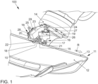
- FIG. 1 A roller folding device 100 is shown schematically, by means of which an edge region 10 of a sheet metal part 11 can be folded.
- the sheet metal part 11 can have an inner sheet 12 and an outer sheet 13, which can be connected to one another by folding the edge region 10, which is part of the outer sheet 13 in the embodiment shown here.
- the roller folding device 100 has a robot-guided roller folding head 14, on which a folding roller 15 is arranged, by means of which the edge region 10 of the sheet metal part 11 is folded.
- the folding roller 15 is moved in the folding direction R on the edge region 10 of the sheet metal part 11 by means of the roller folding head 14.
- the roller folding device 100 has a holding device 16, which serves to hold the sheet metal part 11 in a defined position during folding, in particular to hold it in place, in order to prevent the sheet metal part 11 from slipping during the folding process.
- the holding device 16 is designed in such a way that it can apply a pressing force directly to the edge region 10 of the sheet metal part 11 to be folded.
- the holding device 16 is divided into two, so that a pressing force can be applied to the edge region 10 of the sheet metal part 11 to be folded at two different, separately arranged positions.
- the holding device 16 is divided into two such that a holding force in the folding direction R can be applied in front of and behind the folding roller 15 to the edge region 10 of the sheet metal part 11 to be folded.
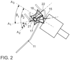
- the holding device 16 has a first pressure roller 17 and a second pressure roller 18.
- the first pressure roller 17 is arranged in front of the folding roller 15 in the folding direction R and the second pressure roller 18 is arranged behind the folding roller 15 in the folding direction R.
- the folding roller 15 is thus positioned between the two pressure rollers 17, 18.
- the pressure rollers 17, 18 are each positioned as close as possible to the folding roller 15 and thus at a short distance from the folding roller 15.
- the pressure rollers 17, 18 do not have their own drive, but rather they rotate about their axis of rotation A 1 , A 2 by moving the roller folding head 14 and thus the folding roller 15 along the edge region 10 of the sheet metal part 11 to be folded, so that the pressure rollers 17, 18 follow the movement of the folding roller 15.
- the holding device 16 and thus the two pressure rollers 17, 18 are mounted on the robot-guided roller hemming head 14 and are therefore attached to it, so that the holding device 16 or the pressure rollers 17, 18 do not require their own guide or receiving device separately from the roller hemming head 14.
- the pressure rollers 17, 18 are each mounted or attached to the roller seaming head 14 via a receiving element 19, 20.
- the first pressure roller 17 is held on the first receiving element 19 by means of a first axle element 21 which extends along the rotation axis A 1 of the first pressure roller 17.
- the first axle element 21 is mounted on the first receiving element 19 in front of and behind the first pressure roller 17.
- the first pressure roller 17 is therefore mounted on both sides or two sides.
- the first receiving element 19 surrounds the first pressure roller 17 in a U-shape.
- the second pressure roller 18 is held on the second receiving element 20 by means of a second axle element 22 extending along the axis of rotation A 2 of the second pressure roller 18.
- the second axle element 22 is mounted on the second receiving element 20 in front of and behind the second pressure roller 18.
- the second pressure roller 18 is therefore also mounted on both sides or two sides.
- the second receiving element 20 surrounds the second pressure roller 18 in a U-shape.
- Both the first receiving element 19 and the second receiving element 20 are attached by means of a screw connection to the roller folding head 14, in particular a flange 23 of the roller folding head 14, on which the folding roller 15 is also rotatably mounted.
- the first pressure roller 17 and the second pressure roller 18 are each resiliently mounted.
- first pressure roller 17 and the second pressure roller 18 are mounted in such a way that they can each be tilted together with their axle elements 21, 22 relative to their axis of rotation A 1 , A 2 by applying a force to the axle elements 21, 22, as in Fig. 2 is indicated by the arrows.
- the two pressure rollers 17, 18 can be arranged inclined to one another by the second pressure roller 18, in particular the axis of rotation A 2 of the second pressure roller 18 or the second axis element 22, on which the second pressure roller 18 is mounted, at an angle 5° ⁇ ⁇ ⁇ 60° inclined to the first pressure roller 17, in particular the axis of rotation A 1 of the first pressure roller 17 or the first axle element 21, on which the first pressure roller 17 is mounted, can be positioned.
- the angle ⁇ is preferably adjustable as desired and/or can change depending on the contour of the edge region 10 of the sheet metal part 11 to be folded.
- the folding roller 15 is also arranged inclined to the two pressure rollers 17, 18.
- the axis of rotation A 3 of the folding roller 15 is positioned at an angle of 10° ⁇ ⁇ 1 ⁇ 90° to the axis of rotation A2 of the second pressure roller 18 and at an angle of 10° ⁇ ⁇ 2 ⁇ 90° to the axis of rotation A1 of the first pressure roller 17.
- the angle ⁇ 2 is greater than the angle ⁇ 1 , so that the inclination of the second pressure roller 18 to the folding roller 15 is greater than the inclination of the first pressure roller 17 to the folding roller 15.
- the first pressure roller 17 and/or the second pressure roller 18 each have a running surface with which the pressure rollers 17, 18 roll on the edge region 10. These running surfaces of the pressure rollers 17, 18 can be profiled.
- the pressure rollers 17, 18 can each have the shape of a hyperboloid, in which the pressure rollers 17, 18 are cylindrical, with a central constriction.
Landscapes
- Engineering & Computer Science (AREA)
- Mechanical Engineering (AREA)
- Folding Of Thin Sheet-Like Materials, Special Discharging Devices, And Others (AREA)
- Press Drives And Press Lines (AREA)
- Lining Or Joining Of Plastics Or The Like (AREA)
Claims (8)
- Dispositif de pliage à rouleaux (100) pour plier une zone de bord (10) d'une pièce en tôle (11), comportant une tête de pliage à rouleaux (14) guidée par robot, qui présente un rouleau de pliage (15) mobile dans le sens du pliage (R) le long de la zone de bord (10) de la pièce en tôle (11) à plier et un dispositif de maintien (16) pour maintenir la pièce en tôle (11) dans une position définie, au moyen duquel une force de pression peut être appliquée directement sur la zone de bord (10) de la pièce en tôle (11),
dans lequel le dispositif de maintien (16) comporte un premier rouleau de pression (17), qui est disposé devant le rouleau de pliage (15) dans la direction de pliage (R), et un deuxième rouleau de pression (18), qui est disposé derrière rouleau de pliage (15) dans la direction de pliage (R), dans lequel le dispositif de maintien (16) est monté sur la tête de pliage (14) à rouleaux guidée par robot, caractérisé en ce que le deuxième rouleau de pression (18) est incliné d'un angle de 5° ≤ α ≤ 60° pour que le premier rouleau de pression (17) puisse être positionné. - Dispositif de pliage à rouleaux (100) selon la revendication 1, caractérisé en ce que le premier rouleau de pression (17) et/ou le deuxième rouleau de pression (18) sont montés élastiquement.
- Dispositif de pliage à rouleaux (100) selon une des revendications 1 et 2, caractérisé en ce que le premier rouleau de pression (17) et/ou le deuxième rouleau de pression (18) sont inclinables par rapport à leur axe de rotation (A1, A2).
- Dispositif de pliage à rouleaux (100) selon une des revendications 1 à 3, caractérisé en ce que le premier rouleau de pression (17) est maintenu à un premier élément de réception (19) au moyen d'un premier élément d'essieu (21) s'étendant le long du l'axe de rotation (A1) du premier rouleau de pression (17), dans lequel le premier élément d'essieu (21) est monté sur le premier élément de réception (19) devant et derrière le premier rouleau de pression (17).
- Dispositif de pliage à rouleaux (100) selon une des revendications 1 à 4, caractérisé en ce que le deuxième rouleau de pression (18) est maintenu à un deuxième élément de réception (22) au moyen d'un deuxième élément d'essieu (22) s'étendant le long du l'axe de rotation (A2) du deuxième rouleau de pression (18), sachant que le deuxième élément d'essieu (22) est monté sur le deuxième élément de réception (20) devant et derrière le deuxième rouleau de pression (18) .
- Dispositif de pliage à rouleaux (100) selon une des revendications 1 à 5, caractérisé en ce que le premier rouleau de pression (17) et/ou le deuxième rouleau de pression (18) sont profilés.
- Dispositif de pliage à rouleaux (100) selon une des revendications 1 à 6, caractérisé en ce que le premier rouleau de pression (17) et/ou le deuxième rouleau de pression (18) sont conçus chacun sous la forme d'un hyperboloïde.
- Procédé de pliage d'une zone de bord (10) d'une pièce en tôle (11), dans lequel un rouleau de pliage (15) d'une tête de pliage à rouleaux (14) guidée par robot est déplacé dans la direction de pliage (R) le long de la zone de bord (10) de la pièce en tôle (11) à plier et de la pièce en tôle (11) lors du déplacement du rouleau de pliage (15) dans la direction de pliage (R) au moyen d'un premier rouleau de pression (17), qui est disposé devant le rouleau de pliage (15) dans la direction de pliage (R), et un deuxième rouleau de pression (18), qui est disposé derrière le rouleau de pliage (15) dans la direction de pliage (R), qui comporte un dispositif de maintien (16) dans lequel la tête de sertissage à rouleau (14) guidée par robot est maintenue dans une position définie au moyen du dispositif de maintien (16), en appliquant une force de pression directement sur la zone de bord (10) de la pièce en tôle (11), caractérisé en ce que le deuxième rouleau de pression (18) peut être positionné à une inclinaison de de 5° ≤ α ≤ 60° par rapport au premier rouleau de pression (17).
Applications Claiming Priority (1)
| Application Number | Priority Date | Filing Date | Title |
|---|---|---|---|
| DE102016211571.5A DE102016211571A1 (de) | 2016-06-28 | 2016-06-28 | Rollfalzvorrichtung und Verfahren zum Falzen eines Kantenbereichs eines Blechteils |
Publications (2)
| Publication Number | Publication Date |
|---|---|
| EP3263241A1 EP3263241A1 (fr) | 2018-01-03 |
| EP3263241B1 true EP3263241B1 (fr) | 2024-01-17 |
Family
ID=58745057
Family Applications (1)
| Application Number | Title | Priority Date | Filing Date |
|---|---|---|---|
| EP17171453.8A Active EP3263241B1 (fr) | 2016-06-28 | 2017-05-17 | Dispositif de repliage à rouleaux et procédé de repliage d'une zone de rebord d'une pièce de tôlerie |
Country Status (3)
| Country | Link |
|---|---|
| EP (1) | EP3263241B1 (fr) |
| CN (1) | CN107537942B (fr) |
| DE (1) | DE102016211571A1 (fr) |
Families Citing this family (10)
| Publication number | Priority date | Publication date | Assignee | Title |
|---|---|---|---|---|
| CN110328266B (zh) * | 2019-08-16 | 2024-04-09 | 江苏三迪机车制造有限公司 | 折边组件及折边方法 |
| JP7450359B2 (ja) | 2019-10-01 | 2024-03-15 | 株式会社キャタラー | 排ガス浄化用触媒 |
| DE102020125935B4 (de) | 2020-10-05 | 2023-05-17 | Audi Aktiengesellschaft | Vorrichtung und Verfahren zum Umformen eines Falzflansches |
| CN112676468B (zh) * | 2021-01-06 | 2025-05-06 | 烟台宇信科技有限公司 | 一种汽车白车身闭合件的自动滚边设备 |
| CN113714358B (zh) * | 2021-08-26 | 2025-01-14 | 常州孟腾智能装备有限公司 | 一种钣金件开窗的滚动折边装置及其折边方法 |
| CN115213313B (zh) * | 2021-11-12 | 2025-08-08 | 广州汽车集团股份有限公司 | 一种滚边设备 |
| CN114042789B (zh) * | 2021-12-02 | 2022-08-09 | 上海交通大学 | 板材随动式机器人柔性渐进翻边成形优化方法 |
| CN115255084B (zh) * | 2022-05-16 | 2025-03-21 | 东风柳州汽车有限公司 | 汽车轮眉滚边胎膜清洁装置 |
| CN115283559B (zh) * | 2022-07-22 | 2024-05-31 | 精诚工科汽车系统有限公司 | 滚边方法 |
| CN115555448B (zh) * | 2022-09-30 | 2025-07-25 | 精诚工科汽车系统有限公司 | 预滚边工装及预滚边方法 |
Family Cites Families (10)
| Publication number | Priority date | Publication date | Assignee | Title |
|---|---|---|---|---|
| DE2544875A1 (de) * | 1975-10-07 | 1977-04-14 | Knudson Gary Art | Vorrichtung zum ausbilden von naehten |
| US4989308A (en) * | 1988-06-20 | 1991-02-05 | Butler Manufacturing Company | Bidirectional roof seaming machine |
| US5623805A (en) * | 1995-04-20 | 1997-04-29 | M.I.C. Industries, Inc. | Seaming device capable of seaming curved and straight panels |
| DE29606725U1 (de) * | 1996-04-16 | 1996-08-14 | Trumpf Gmbh & Co, 71254 Ditzingen | Maschine zum Umbiegen eines Blechrandes |
| EP1097759A4 (fr) | 1998-09-08 | 2003-07-23 | Tri Engineering Company Ltd | Dispositif d'usinage du type laminoir a galets |
| DE102004016385B3 (de) * | 2004-04-02 | 2005-09-08 | Audi Ag | Rollfalzvorrichtung zum Verbinden der Plattenränder zweier Blechplatten mittels eines Falzrandes |
| DE102005004474B3 (de) * | 2005-01-31 | 2006-08-31 | Edag Engineering + Design Ag | Bördelvorrichtung und Bördelverfahren zum Umlegen eines Bördelstegs eines Bauteils um eine Bördelkante |
| EP2108466B1 (fr) * | 2005-12-05 | 2013-03-20 | Honda Motor Co., Ltd. | Procede de rabattage et dispositif de rabattage |
| DE102012004054A1 (de) * | 2012-03-02 | 2013-09-05 | Volkswagen Ag | Rollfalzkopf, Anlage und Verfahren zum Rollfalzen mit einem Tandemrollensatz |
| DE102014201998A1 (de) * | 2014-02-04 | 2015-08-20 | Volkswagen Aktiengesellschaft | Verfahren zum Verbinden und Prägevorrichtung |
-
2016
- 2016-06-28 DE DE102016211571.5A patent/DE102016211571A1/de not_active Withdrawn
-
2017
- 2017-05-17 EP EP17171453.8A patent/EP3263241B1/fr active Active
- 2017-06-28 CN CN201710508241.0A patent/CN107537942B/zh active Active
Also Published As
| Publication number | Publication date |
|---|---|
| DE102016211571A1 (de) | 2017-12-28 |
| CN107537942A (zh) | 2018-01-05 |
| EP3263241A1 (fr) | 2018-01-03 |
| CN107537942B (zh) | 2020-08-18 |
Similar Documents
| Publication | Publication Date | Title |
|---|---|---|
| EP3263241B1 (fr) | Dispositif de repliage à rouleaux et procédé de repliage d'une zone de rebord d'une pièce de tôlerie | |
| EP0394531B1 (fr) | Machine à sertir | |
| WO2003018227A1 (fr) | Dispositif de sertissage pour replier l'arete a sertir d'une piece par repliage roule avec au moins deux etapes de pliage | |
| DE202004012580U1 (de) | Falzwerkzeug zum Roboterfalzen | |
| DE2617755A1 (de) | Rollenformmaschine zur formgebenden bearbeitung von blechen u.dgl., insbesondere zum aufbiegen, kanten oder boerdeln usw. der raender von metallblechen | |
| DE10306966A1 (de) | Plattenverarbeitende Maschine mit Biegefunktion und Werkzeug hierfür | |
| WO2018055184A1 (fr) | Outil et machine-outil ainsi que procédé d'usinage de pièces en forme de plaque, en particulier de tôles | |
| EP3763454B1 (fr) | Tête de pliage au rouleau et procédé de pliage au rouleau d'un bord de pliage à l'aide d'un robot sans technique d'outillage de précision extérieure | |
| EP1916043B1 (fr) | Machine de cintrage ou de pliage | |
| DE102016119435A1 (de) | Werkzeug und Werkzeugmaschine sowie Verfahren zum Bearbeiten von plattenförmigen Werkstücken | |
| EP1495816B1 (fr) | Outil de pliage à segments de butée de la pièce réglables ainsi que machine à plier comprenant un tel outil de pliage | |
| EP3515617B1 (fr) | Outil et machine-outil ainsi que procédé d'usinage de pièces en forme de plaque | |
| EP0995509A1 (fr) | Plieuse | |
| EP2576095B1 (fr) | Dispositif pour déformer un élément d'un semi-produit notamment plan | |
| EP1162011B1 (fr) | Appareil pour plier le bord d'une pièce par repliage à rouleaux | |
| DE3709018C2 (de) | Vorrichtung zum Biegebearbeiten von Blechtafeln | |
| DE29914967U1 (de) | Bördeleinrichtung mit einem mehrachsigen Manipulator | |
| DE102005042362B4 (de) | Falzvorrichtung für einen Rollfalzkopf einer Rollfalzvorrichtung | |
| DE102020125935B4 (de) | Vorrichtung und Verfahren zum Umformen eines Falzflansches | |
| WO2021013810A1 (fr) | Outil et procédé pour l'usinage de pièces en forme de plaques, en particulier de tôles | |
| DE19844248B4 (de) | Vorrichtung zum Falzen, insbesondere zur Verbindung von zwei oder mehr Blechteilen | |
| DE102014012643A1 (de) | Verfahren und Werkzeug zum Bearbeiten von Werkstücken | |
| EP1459815B1 (fr) | Dispositif de pliage, en particulier pour des materiaux de profile en tôle | |
| DE10314517A1 (de) | Schwenkbiegemaschine, insbesondere für Blechprofilmaterialien | |
| DE102017115285A1 (de) | Flexibles Falzwerkzeug |
Legal Events
| Date | Code | Title | Description |
|---|---|---|---|
| PUAI | Public reference made under article 153(3) epc to a published international application that has entered the european phase |
Free format text: ORIGINAL CODE: 0009012 |
|
| STAA | Information on the status of an ep patent application or granted ep patent |
Free format text: STATUS: THE APPLICATION HAS BEEN PUBLISHED |
|
| AK | Designated contracting states |
Kind code of ref document: A1 Designated state(s): AL AT BE BG CH CY CZ DE DK EE ES FI FR GB GR HR HU IE IS IT LI LT LU LV MC MK MT NL NO PL PT RO RS SE SI SK SM TR |
|
| AX | Request for extension of the european patent |
Extension state: BA ME |
|
| STAA | Information on the status of an ep patent application or granted ep patent |
Free format text: STATUS: REQUEST FOR EXAMINATION WAS MADE |
|
| 17P | Request for examination filed |
Effective date: 20180702 |
|
| RBV | Designated contracting states (corrected) |
Designated state(s): AL AT BE BG CH CY CZ DE DK EE ES FI FR GB GR HR HU IE IS IT LI LT LU LV MC MK MT NL NO PL PT RO RS SE SI SK SM TR |
|
| STAA | Information on the status of an ep patent application or granted ep patent |
Free format text: STATUS: EXAMINATION IS IN PROGRESS |
|
| 17Q | First examination report despatched |
Effective date: 20210326 |
|
| P01 | Opt-out of the competence of the unified patent court (upc) registered |
Effective date: 20230529 |
|
| GRAP | Despatch of communication of intention to grant a patent |
Free format text: ORIGINAL CODE: EPIDOSNIGR1 |
|
| STAA | Information on the status of an ep patent application or granted ep patent |
Free format text: STATUS: GRANT OF PATENT IS INTENDED |
|
| INTG | Intention to grant announced |
Effective date: 20230816 |
|
| GRAS | Grant fee paid |
Free format text: ORIGINAL CODE: EPIDOSNIGR3 |
|
| GRAA | (expected) grant |
Free format text: ORIGINAL CODE: 0009210 |
|
| STAA | Information on the status of an ep patent application or granted ep patent |
Free format text: STATUS: THE PATENT HAS BEEN GRANTED |
|
| AK | Designated contracting states |
Kind code of ref document: B1 Designated state(s): AL AT BE BG CH CY CZ DE DK EE ES FI FR GB GR HR HU IE IS IT LI LT LU LV MC MK MT NL NO PL PT RO RS SE SI SK SM TR |
|
| REG | Reference to a national code |
Ref country code: GB Ref legal event code: FG4D Free format text: NOT ENGLISH |
|
| REG | Reference to a national code |
Ref country code: DE Ref legal event code: R096 Ref document number: 502017015759 Country of ref document: DE |
|
| REG | Reference to a national code |
Ref country code: CH Ref legal event code: EP |
|
| REG | Reference to a national code |
Ref country code: IE Ref legal event code: FG4D Free format text: LANGUAGE OF EP DOCUMENT: GERMAN |
|
| REG | Reference to a national code |
Ref country code: LT Ref legal event code: MG9D |
|
| REG | Reference to a national code |
Ref country code: NL Ref legal event code: MP Effective date: 20240117 |
|
| PG25 | Lapsed in a contracting state [announced via postgrant information from national office to epo] |
Ref country code: NL Free format text: LAPSE BECAUSE OF FAILURE TO SUBMIT A TRANSLATION OF THE DESCRIPTION OR TO PAY THE FEE WITHIN THE PRESCRIBED TIME-LIMIT Effective date: 20240117 |
|
| PG25 | Lapsed in a contracting state [announced via postgrant information from national office to epo] |
Ref country code: NL Free format text: LAPSE BECAUSE OF FAILURE TO SUBMIT A TRANSLATION OF THE DESCRIPTION OR TO PAY THE FEE WITHIN THE PRESCRIBED TIME-LIMIT Effective date: 20240117 |
|
| PG25 | Lapsed in a contracting state [announced via postgrant information from national office to epo] |
Ref country code: IS Free format text: LAPSE BECAUSE OF FAILURE TO SUBMIT A TRANSLATION OF THE DESCRIPTION OR TO PAY THE FEE WITHIN THE PRESCRIBED TIME-LIMIT Effective date: 20240517 |
|
| PG25 | Lapsed in a contracting state [announced via postgrant information from national office to epo] |
Ref country code: LT Free format text: LAPSE BECAUSE OF FAILURE TO SUBMIT A TRANSLATION OF THE DESCRIPTION OR TO PAY THE FEE WITHIN THE PRESCRIBED TIME-LIMIT Effective date: 20240117 |
|
| PG25 | Lapsed in a contracting state [announced via postgrant information from national office to epo] |
Ref country code: GR Free format text: LAPSE BECAUSE OF FAILURE TO SUBMIT A TRANSLATION OF THE DESCRIPTION OR TO PAY THE FEE WITHIN THE PRESCRIBED TIME-LIMIT Effective date: 20240418 |
|
| PG25 | Lapsed in a contracting state [announced via postgrant information from national office to epo] |
Ref country code: RS Free format text: LAPSE BECAUSE OF FAILURE TO SUBMIT A TRANSLATION OF THE DESCRIPTION OR TO PAY THE FEE WITHIN THE PRESCRIBED TIME-LIMIT Effective date: 20240417 Ref country code: HR Free format text: LAPSE BECAUSE OF FAILURE TO SUBMIT A TRANSLATION OF THE DESCRIPTION OR TO PAY THE FEE WITHIN THE PRESCRIBED TIME-LIMIT Effective date: 20240117 |
|
| PG25 | Lapsed in a contracting state [announced via postgrant information from national office to epo] |
Ref country code: ES Free format text: LAPSE BECAUSE OF FAILURE TO SUBMIT A TRANSLATION OF THE DESCRIPTION OR TO PAY THE FEE WITHIN THE PRESCRIBED TIME-LIMIT Effective date: 20240117 |
|
| PG25 | Lapsed in a contracting state [announced via postgrant information from national office to epo] |
Ref country code: RS Free format text: LAPSE BECAUSE OF FAILURE TO SUBMIT A TRANSLATION OF THE DESCRIPTION OR TO PAY THE FEE WITHIN THE PRESCRIBED TIME-LIMIT Effective date: 20240417 Ref country code: NO Free format text: LAPSE BECAUSE OF FAILURE TO SUBMIT A TRANSLATION OF THE DESCRIPTION OR TO PAY THE FEE WITHIN THE PRESCRIBED TIME-LIMIT Effective date: 20240417 Ref country code: LT Free format text: LAPSE BECAUSE OF FAILURE TO SUBMIT A TRANSLATION OF THE DESCRIPTION OR TO PAY THE FEE WITHIN THE PRESCRIBED TIME-LIMIT Effective date: 20240117 Ref country code: IS Free format text: LAPSE BECAUSE OF FAILURE TO SUBMIT A TRANSLATION OF THE DESCRIPTION OR TO PAY THE FEE WITHIN THE PRESCRIBED TIME-LIMIT Effective date: 20240517 Ref country code: HR Free format text: LAPSE BECAUSE OF FAILURE TO SUBMIT A TRANSLATION OF THE DESCRIPTION OR TO PAY THE FEE WITHIN THE PRESCRIBED TIME-LIMIT Effective date: 20240117 Ref country code: GR Free format text: LAPSE BECAUSE OF FAILURE TO SUBMIT A TRANSLATION OF THE DESCRIPTION OR TO PAY THE FEE WITHIN THE PRESCRIBED TIME-LIMIT Effective date: 20240418 Ref country code: FI Free format text: LAPSE BECAUSE OF FAILURE TO SUBMIT A TRANSLATION OF THE DESCRIPTION OR TO PAY THE FEE WITHIN THE PRESCRIBED TIME-LIMIT Effective date: 20240117 Ref country code: ES Free format text: LAPSE BECAUSE OF FAILURE TO SUBMIT A TRANSLATION OF THE DESCRIPTION OR TO PAY THE FEE WITHIN THE PRESCRIBED TIME-LIMIT Effective date: 20240117 Ref country code: BG Free format text: LAPSE BECAUSE OF FAILURE TO SUBMIT A TRANSLATION OF THE DESCRIPTION OR TO PAY THE FEE WITHIN THE PRESCRIBED TIME-LIMIT Effective date: 20240117 |
|
| PG25 | Lapsed in a contracting state [announced via postgrant information from national office to epo] |
Ref country code: PT Free format text: LAPSE BECAUSE OF FAILURE TO SUBMIT A TRANSLATION OF THE DESCRIPTION OR TO PAY THE FEE WITHIN THE PRESCRIBED TIME-LIMIT Effective date: 20240517 Ref country code: PL Free format text: LAPSE BECAUSE OF FAILURE TO SUBMIT A TRANSLATION OF THE DESCRIPTION OR TO PAY THE FEE WITHIN THE PRESCRIBED TIME-LIMIT Effective date: 20240117 |
|
| PG25 | Lapsed in a contracting state [announced via postgrant information from national office to epo] |
Ref country code: SE Free format text: LAPSE BECAUSE OF FAILURE TO SUBMIT A TRANSLATION OF THE DESCRIPTION OR TO PAY THE FEE WITHIN THE PRESCRIBED TIME-LIMIT Effective date: 20240117 Ref country code: PT Free format text: LAPSE BECAUSE OF FAILURE TO SUBMIT A TRANSLATION OF THE DESCRIPTION OR TO PAY THE FEE WITHIN THE PRESCRIBED TIME-LIMIT Effective date: 20240517 Ref country code: PL Free format text: LAPSE BECAUSE OF FAILURE TO SUBMIT A TRANSLATION OF THE DESCRIPTION OR TO PAY THE FEE WITHIN THE PRESCRIBED TIME-LIMIT Effective date: 20240117 Ref country code: LV Free format text: LAPSE BECAUSE OF FAILURE TO SUBMIT A TRANSLATION OF THE DESCRIPTION OR TO PAY THE FEE WITHIN THE PRESCRIBED TIME-LIMIT Effective date: 20240117 |
|
| PG25 | Lapsed in a contracting state [announced via postgrant information from national office to epo] |
Ref country code: DK Free format text: LAPSE BECAUSE OF FAILURE TO SUBMIT A TRANSLATION OF THE DESCRIPTION OR TO PAY THE FEE WITHIN THE PRESCRIBED TIME-LIMIT Effective date: 20240117 |
|
| PG25 | Lapsed in a contracting state [announced via postgrant information from national office to epo] |
Ref country code: SM Free format text: LAPSE BECAUSE OF FAILURE TO SUBMIT A TRANSLATION OF THE DESCRIPTION OR TO PAY THE FEE WITHIN THE PRESCRIBED TIME-LIMIT Effective date: 20240117 |
|
| REG | Reference to a national code |
Ref country code: DE Ref legal event code: R097 Ref document number: 502017015759 Country of ref document: DE |
|
| PG25 | Lapsed in a contracting state [announced via postgrant information from national office to epo] |
Ref country code: EE Free format text: LAPSE BECAUSE OF FAILURE TO SUBMIT A TRANSLATION OF THE DESCRIPTION OR TO PAY THE FEE WITHIN THE PRESCRIBED TIME-LIMIT Effective date: 20240117 Ref country code: CZ Free format text: LAPSE BECAUSE OF FAILURE TO SUBMIT A TRANSLATION OF THE DESCRIPTION OR TO PAY THE FEE WITHIN THE PRESCRIBED TIME-LIMIT Effective date: 20240117 |
|
| PG25 | Lapsed in a contracting state [announced via postgrant information from national office to epo] |
Ref country code: SK Free format text: LAPSE BECAUSE OF FAILURE TO SUBMIT A TRANSLATION OF THE DESCRIPTION OR TO PAY THE FEE WITHIN THE PRESCRIBED TIME-LIMIT Effective date: 20240117 |
|
| PG25 | Lapsed in a contracting state [announced via postgrant information from national office to epo] |
Ref country code: SM Free format text: LAPSE BECAUSE OF FAILURE TO SUBMIT A TRANSLATION OF THE DESCRIPTION OR TO PAY THE FEE WITHIN THE PRESCRIBED TIME-LIMIT Effective date: 20240117 Ref country code: SK Free format text: LAPSE BECAUSE OF FAILURE TO SUBMIT A TRANSLATION OF THE DESCRIPTION OR TO PAY THE FEE WITHIN THE PRESCRIBED TIME-LIMIT Effective date: 20240117 Ref country code: RO Free format text: LAPSE BECAUSE OF FAILURE TO SUBMIT A TRANSLATION OF THE DESCRIPTION OR TO PAY THE FEE WITHIN THE PRESCRIBED TIME-LIMIT Effective date: 20240117 Ref country code: EE Free format text: LAPSE BECAUSE OF FAILURE TO SUBMIT A TRANSLATION OF THE DESCRIPTION OR TO PAY THE FEE WITHIN THE PRESCRIBED TIME-LIMIT Effective date: 20240117 Ref country code: DK Free format text: LAPSE BECAUSE OF FAILURE TO SUBMIT A TRANSLATION OF THE DESCRIPTION OR TO PAY THE FEE WITHIN THE PRESCRIBED TIME-LIMIT Effective date: 20240117 Ref country code: CZ Free format text: LAPSE BECAUSE OF FAILURE TO SUBMIT A TRANSLATION OF THE DESCRIPTION OR TO PAY THE FEE WITHIN THE PRESCRIBED TIME-LIMIT Effective date: 20240117 |
|
| PLBE | No opposition filed within time limit |
Free format text: ORIGINAL CODE: 0009261 |
|
| STAA | Information on the status of an ep patent application or granted ep patent |
Free format text: STATUS: NO OPPOSITION FILED WITHIN TIME LIMIT |
|
| PG25 | Lapsed in a contracting state [announced via postgrant information from national office to epo] |
Ref country code: IT Free format text: LAPSE BECAUSE OF FAILURE TO SUBMIT A TRANSLATION OF THE DESCRIPTION OR TO PAY THE FEE WITHIN THE PRESCRIBED TIME-LIMIT Effective date: 20240117 |
|
| 26N | No opposition filed |
Effective date: 20241018 |
|
| REG | Reference to a national code |
Ref country code: CH Ref legal event code: PL |
|
| PG25 | Lapsed in a contracting state [announced via postgrant information from national office to epo] |
Ref country code: IT Free format text: LAPSE BECAUSE OF FAILURE TO SUBMIT A TRANSLATION OF THE DESCRIPTION OR TO PAY THE FEE WITHIN THE PRESCRIBED TIME-LIMIT Effective date: 20240117 |
|
| PG25 | Lapsed in a contracting state [announced via postgrant information from national office to epo] |
Ref country code: MC Free format text: LAPSE BECAUSE OF FAILURE TO SUBMIT A TRANSLATION OF THE DESCRIPTION OR TO PAY THE FEE WITHIN THE PRESCRIBED TIME-LIMIT Effective date: 20240117 |
|
| PG25 | Lapsed in a contracting state [announced via postgrant information from national office to epo] |
Ref country code: LU Free format text: LAPSE BECAUSE OF NON-PAYMENT OF DUE FEES Effective date: 20240517 |
|
| PG25 | Lapsed in a contracting state [announced via postgrant information from national office to epo] |
Ref country code: MC Free format text: LAPSE BECAUSE OF FAILURE TO SUBMIT A TRANSLATION OF THE DESCRIPTION OR TO PAY THE FEE WITHIN THE PRESCRIBED TIME-LIMIT Effective date: 20240117 Ref country code: LU Free format text: LAPSE BECAUSE OF NON-PAYMENT OF DUE FEES Effective date: 20240517 Ref country code: CH Free format text: LAPSE BECAUSE OF NON-PAYMENT OF DUE FEES Effective date: 20240531 |
|
| REG | Reference to a national code |
Ref country code: BE Ref legal event code: MM Effective date: 20240531 |
|
| PG25 | Lapsed in a contracting state [announced via postgrant information from national office to epo] |
Ref country code: IE Free format text: LAPSE BECAUSE OF NON-PAYMENT OF DUE FEES Effective date: 20240517 |
|
| PG25 | Lapsed in a contracting state [announced via postgrant information from national office to epo] |
Ref country code: SI Free format text: LAPSE BECAUSE OF FAILURE TO SUBMIT A TRANSLATION OF THE DESCRIPTION OR TO PAY THE FEE WITHIN THE PRESCRIBED TIME-LIMIT Effective date: 20240117 Ref country code: BE Free format text: LAPSE BECAUSE OF NON-PAYMENT OF DUE FEES Effective date: 20240531 |
|
| PGFP | Annual fee paid to national office [announced via postgrant information from national office to epo] |
Ref country code: DE Payment date: 20250521 Year of fee payment: 9 |
|
| PGFP | Annual fee paid to national office [announced via postgrant information from national office to epo] |
Ref country code: GB Payment date: 20250527 Year of fee payment: 9 |
|
| REG | Reference to a national code |
Ref country code: AT Ref legal event code: MM01 Ref document number: 1650222 Country of ref document: AT Kind code of ref document: T Effective date: 20240517 |
|
| PGFP | Annual fee paid to national office [announced via postgrant information from national office to epo] |
Ref country code: FR Payment date: 20250523 Year of fee payment: 9 |
|
| PG25 | Lapsed in a contracting state [announced via postgrant information from national office to epo] |
Ref country code: AT Free format text: LAPSE BECAUSE OF NON-PAYMENT OF DUE FEES Effective date: 20240517 |
|
| PG25 | Lapsed in a contracting state [announced via postgrant information from national office to epo] |
Ref country code: CY Free format text: LAPSE BECAUSE OF FAILURE TO SUBMIT A TRANSLATION OF THE DESCRIPTION OR TO PAY THE FEE WITHIN THE PRESCRIBED TIME-LIMIT; INVALID AB INITIO Effective date: 20170517 |
|
| PG25 | Lapsed in a contracting state [announced via postgrant information from national office to epo] |
Ref country code: HU Free format text: LAPSE BECAUSE OF FAILURE TO SUBMIT A TRANSLATION OF THE DESCRIPTION OR TO PAY THE FEE WITHIN THE PRESCRIBED TIME-LIMIT; INVALID AB INITIO Effective date: 20170517 |