EP3263246A1 - Procédé et machine de coulée continue d'une fonte métallique - Google Patents
Procédé et machine de coulée continue d'une fonte métallique Download PDFInfo
- Publication number
- EP3263246A1 EP3263246A1 EP17177553.9A EP17177553A EP3263246A1 EP 3263246 A1 EP3263246 A1 EP 3263246A1 EP 17177553 A EP17177553 A EP 17177553A EP 3263246 A1 EP3263246 A1 EP 3263246A1
- Authority
- EP
- European Patent Office
- Prior art keywords
- temperature
- molten metal
- casting
- ladle
- casting machine
- Prior art date
- Legal status (The legal status is an assumption and is not a legal conclusion. Google has not performed a legal analysis and makes no representation as to the accuracy of the status listed.)
- Withdrawn
Links
Images

Classifications
-
- B—PERFORMING OPERATIONS; TRANSPORTING
- B22—CASTING; POWDER METALLURGY
- B22D—CASTING OF METALS; CASTING OF OTHER SUBSTANCES BY THE SAME PROCESSES OR DEVICES
- B22D11/00—Continuous casting of metals, i.e. casting in indefinite lengths
- B22D11/14—Plants for continuous casting
- B22D11/141—Plants for continuous casting for vertical casting
-
- B—PERFORMING OPERATIONS; TRANSPORTING
- B22—CASTING; POWDER METALLURGY
- B22D—CASTING OF METALS; CASTING OF OTHER SUBSTANCES BY THE SAME PROCESSES OR DEVICES
- B22D11/00—Continuous casting of metals, i.e. casting in indefinite lengths
- B22D11/10—Supplying or treating molten metal
- B22D11/103—Distributing the molten metal, e.g. using runners, floats, distributors
-
- B—PERFORMING OPERATIONS; TRANSPORTING
- B22—CASTING; POWDER METALLURGY
- B22D—CASTING OF METALS; CASTING OF OTHER SUBSTANCES BY THE SAME PROCESSES OR DEVICES
- B22D11/00—Continuous casting of metals, i.e. casting in indefinite lengths
- B22D11/16—Controlling or regulating processes or operations
-
- B—PERFORMING OPERATIONS; TRANSPORTING
- B22—CASTING; POWDER METALLURGY
- B22D—CASTING OF METALS; CASTING OF OTHER SUBSTANCES BY THE SAME PROCESSES OR DEVICES
- B22D2/00—Arrangement of indicating or measuring devices, e.g. for temperature or viscosity of the fused mass
- B22D2/006—Arrangement of indicating or measuring devices, e.g. for temperature or viscosity of the fused mass for the temperature of the molten metal
-
- B—PERFORMING OPERATIONS; TRANSPORTING
- B22—CASTING; POWDER METALLURGY
- B22D—CASTING OF METALS; CASTING OF OTHER SUBSTANCES BY THE SAME PROCESSES OR DEVICES
- B22D41/00—Casting melt-holding vessels, e.g. ladles, tundishes, cups or the like
- B22D41/005—Casting melt-holding vessels, e.g. ladles, tundishes, cups or the like with heating or cooling means
- B22D41/01—Heating means
- B22D41/015—Heating means with external heating, i.e. the heat source not being a part of the ladle
-
- B—PERFORMING OPERATIONS; TRANSPORTING
- B22—CASTING; POWDER METALLURGY
- B22D—CASTING OF METALS; CASTING OF OTHER SUBSTANCES BY THE SAME PROCESSES OR DEVICES
- B22D41/00—Casting melt-holding vessels, e.g. ladles, tundishes, cups or the like
- B22D41/50—Pouring-nozzles
- B22D41/60—Pouring-nozzles with heating or cooling means
Definitions
- the Japanese patent application discloses a method for controlling the temperature of a molten metal in a distributor trough.
- the temperature in the distributor trough is estimated at different times and adjusted to a desired value.
- the adjustment is made by means of a plasma torch, the power of which depends on the difference between the estimated actual temperature and a predetermined target temperature for the melt.
- the molten metal is produced in the ladle with little overheating and logistically optimized fed to the continuous casting, taking into account the current Pfannenmentss (old or new).
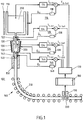
- FIG. 10 shows a casting machine 100 with the following components: a ladle 110 filled with a molten metal 200. Via a shadow tube 120 or a pouring box 120, the molten metal can pass from the ladle 110 into a distributor trough 130. In turn, the molten metal can flow out of the distributor channel via a dip nozzle 140 into a mold 150. At the exit of the mold 150, a cast strand 210 is pulled out with initially liquid core, which is subsequently supported in a strand guide 160 and typically transferred to the horizontal. On its way through the strand guide 160 of the cast strand 210 solidifies.
- each of the components casting ladle 110, shadow tube or casting box 120, distributor channel 130 and immersion nozzle 140 can be assigned its own temperature control loop.
- a G tellpfannenregelnik 116 may be provided with a ladle-temperature measuring device 114 for measuring the actual temperature T G-lf the molten metal 200 in the ladle 110.
- the ladle temperature control circuit 116 provides that this actual temperature with a predetermined setpoint temperature T G target for the temperature of the melt in the ladle is compared and any temperature difference detected as a control deviation is fed to a ladle temperature controller 118 as an input variable.
- the temperature controller 118 generates
- a distributor trough temperature control circuit 136 may be provided with a distributor trough temperature measuring device 134 for measuring the actual temperature T V-actual of the molten metal 200 in the distributor trough 130.
- the tundish temperature control circuit 136 provides that this actual temperature a predetermined setpoint temperature T V target for the temperature of the melt in the distributor trough is compared and a possibly detected temperature difference is supplied as a control deviation to a distributor trough temperature controller 138 as an input variable.
- the temperature controller 138 generates a control signal Q V for a distribution channel heater 132, which acts as an actuator in the control circuit 136.
- the distribution channel temperature controller 138 generates the control signal such that the control difference supplied to it becomes as close as possible to 0, ie that the temperature of the molten metal in the distributor channel to the value of the predetermined target temperature T V target or at least in a predetermined superheat temperature target Value window for the molten metal is held in the distributor trough.
- a immersion nozzle temperature control circuit 146 may be provided with a submersible temperature measuring device 144 for measuring the actual temperature T T-Ist of the molten metal 200 in the immersion nozzle 140.
- the immersion nozzle temperature control circuit 146 provides that this actual temperature with a predetermined setpoint temperature T set T for the temperature of the melt in the immersion nozzle is compared, and thereby possibly detected temperature difference as a deviation immersion nozzle temperature controller 148 is supplied as input.
- the temperature controller 148 generates a control signal Q T for a submerged nozzle heater 142, which acts as an actuator in the control loop 146.
- the immersion nozzle temperature controller 148 generates the control signal in such a way that the control difference supplied to it becomes as low as possible, ie, that the temperature of the molten metal in the immersion nozzle is equal to the value of the predetermined target temperature T T target or at least in a predetermined superheat temperature target value. Value window for the molten metal is kept in the immersion nozzle.
- the heaters 112, 122, 132 and / or 142 may operate inductively, capacitively, electromagnetically or with arcs. They can be designed as plasma torches, as pore burners, as open flame or as radiators or they can develop their heating effect by adding alloying agents.
- a sampling device 190 is provided for removing a sample from the casting strand 210.
- the removed sample 220 is fed to an analysis device 180, which is formed, the quality of the sample, and thus the solidified casting strand in terms of at least one Quality characteristic to analyze.
- the analysis can z. B. using the ultrasonic method for macro etching.
- the analysis takes place z. B. with regard to the microstructure or the material composition of the sample.
- the sample can be analyzed as a quality characteristic with regard to the proportion of the globulitic structure, with regard to segregation or with regard to possible voids.
- the determination of the quality of the casting strand, in particular its microstructure can be carried out by optical analysis, e.g. done with the help of X-rays.
- optical analysis e.g. done with the help of X-rays.
- the removal of the sample or the optical analysis can take place at any location in the strand guide; the cast strand only has to be solidified.
- the quality features of the casting strand obtained with the aid of the analysis device are subsequently transmitted to the said desired temperature specification device 170, which is designed, as stated, to specify the desired temperature values for the individual components of the casting machine as a function of the determined quality features of the casting strand 210 ,
- Process models or simulations can be implemented in the desired temperature specification device 170 in order to generate and specify the desired temperature values for the individual control circuits on the basis of the previously determined at least one quality feature, for example the microstructure.
- the calculation of the setpoint temperatures can be within the setpoint temperature setting device 170 using a fuzzy logic set of rules using a neural network or using tables.
- the temperature setpoint calculated using the process models and / or the simulations is only predefined for the at least one component of the casting machine after it has been released by an operator.
- the advantage of the present invention is to realize a very good internal quality of the solidified cast strand 210 with safe operation of the casting machine, with a large operating window and with efficient solidification.
- the invention means a step in the direction of "casting a rolling structure", ie the invention offers the possibility of reducing the rolling effort in a subsequent rolling train by means of improved cast structures.
- the inventive method provides an improvement of the boundary conditions for super-low-head-casting, ie for plants with low height and advantageously with oval-arc shape. This results in a low ferrostatic pressure.
- the method according to the invention has the advantage that softer reduction is no longer necessary.
- the invention offers the advantage that no dynamically controlled, ie softreduction-capable segments with controlled cylinders are required, but instead can be used in the strand guide simpler constructed and thus more cost-effective segments.
- FIG. 2 shows essentially the same casting machine according to the invention as FIG. 1 , The only difference is that according to FIG. 2 no shadow tube is used, but a pouring box, also designated by reference numeral 120. This is typically bricked up on the distributor trough. The ladle 110 may be deposited on the casting box.
- the temperature control circuit 126 operates in this alternative embodiment analogous to the use of a shade tube. Only the heater 122 does not work on the shade tube, but on the casting box.
Landscapes
- Engineering & Computer Science (AREA)
- Mechanical Engineering (AREA)
- Continuous Casting (AREA)
- Casting Support Devices, Ladles, And Melt Control Thereby (AREA)
Applications Claiming Priority (1)
| Application Number | Priority Date | Filing Date | Title |
|---|---|---|---|
| DE102016211786.6A DE102016211786A1 (de) | 2016-06-30 | 2016-06-30 | Verfahren und Gießmaschine zum Gießen einer Metallschmelze |
Publications (1)
| Publication Number | Publication Date |
|---|---|
| EP3263246A1 true EP3263246A1 (fr) | 2018-01-03 |
Family
ID=59152753
Family Applications (1)
| Application Number | Title | Priority Date | Filing Date |
|---|---|---|---|
| EP17177553.9A Withdrawn EP3263246A1 (fr) | 2016-06-30 | 2017-06-23 | Procédé et machine de coulée continue d'une fonte métallique |
Country Status (2)
| Country | Link |
|---|---|
| EP (1) | EP3263246A1 (fr) |
| DE (1) | DE102016211786A1 (fr) |
Cited By (1)
| Publication number | Priority date | Publication date | Assignee | Title |
|---|---|---|---|---|
| CN116000263A (zh) * | 2023-02-01 | 2023-04-25 | 中信戴卡股份有限公司 | 一种合金高压铸造模具、高压铸造装置及浇注方法 |
Citations (7)
| Publication number | Priority date | Publication date | Assignee | Title |
|---|---|---|---|---|
| DE1288760B (de) | 1966-06-14 | 1969-02-06 | Coupette | Verfahren zur Steuerung von Temperatur und Stahlanalyse beim Stranggiessen und Vorrichtung dazu |
| JPS6015054A (ja) * | 1983-07-06 | 1985-01-25 | Ishikawajima Harima Heavy Ind Co Ltd | レ−ドル出口溶融金属温度制御装置 |
| DE19752548A1 (de) * | 1997-11-27 | 1999-06-10 | Schloemann Siemag Ag | Verfahren zur Vorrichtung zum Einstellen und Halten der Temperatur einer Stahlschmelze beim Stranggießen |
| JP2001219250A (ja) | 2000-02-08 | 2001-08-14 | Nippon Steel Corp | タンディッシュ内溶鋼温度の制御装置、方法、及びコンピュータ読み取り可能な記憶媒体 |
| WO2004080628A1 (fr) * | 2003-03-10 | 2004-09-23 | Siemens Aktiengesellschaft | Installation de coulee continue et de laminage pour produire un feuillard d'acier |
| DE102013224184A1 (de) * | 2013-11-27 | 2015-05-28 | Sms Siemag Ag | Verfahren und Vorrichtung zum Bewerten von Innenfehlern an einem kontinuierlich vergossenen Gießprodukt |
| WO2015110984A1 (fr) * | 2014-01-22 | 2015-07-30 | Abb Technology Ltd. | Procédé et appareil pour maintenir une fusion homogénéisée et des champs contrôlés d'un métal fondu |
-
2016
- 2016-06-30 DE DE102016211786.6A patent/DE102016211786A1/de active Pending
-
2017
- 2017-06-23 EP EP17177553.9A patent/EP3263246A1/fr not_active Withdrawn
Patent Citations (7)
| Publication number | Priority date | Publication date | Assignee | Title |
|---|---|---|---|---|
| DE1288760B (de) | 1966-06-14 | 1969-02-06 | Coupette | Verfahren zur Steuerung von Temperatur und Stahlanalyse beim Stranggiessen und Vorrichtung dazu |
| JPS6015054A (ja) * | 1983-07-06 | 1985-01-25 | Ishikawajima Harima Heavy Ind Co Ltd | レ−ドル出口溶融金属温度制御装置 |
| DE19752548A1 (de) * | 1997-11-27 | 1999-06-10 | Schloemann Siemag Ag | Verfahren zur Vorrichtung zum Einstellen und Halten der Temperatur einer Stahlschmelze beim Stranggießen |
| JP2001219250A (ja) | 2000-02-08 | 2001-08-14 | Nippon Steel Corp | タンディッシュ内溶鋼温度の制御装置、方法、及びコンピュータ読み取り可能な記憶媒体 |
| WO2004080628A1 (fr) * | 2003-03-10 | 2004-09-23 | Siemens Aktiengesellschaft | Installation de coulee continue et de laminage pour produire un feuillard d'acier |
| DE102013224184A1 (de) * | 2013-11-27 | 2015-05-28 | Sms Siemag Ag | Verfahren und Vorrichtung zum Bewerten von Innenfehlern an einem kontinuierlich vergossenen Gießprodukt |
| WO2015110984A1 (fr) * | 2014-01-22 | 2015-07-30 | Abb Technology Ltd. | Procédé et appareil pour maintenir une fusion homogénéisée et des champs contrôlés d'un métal fondu |
Cited By (1)
| Publication number | Priority date | Publication date | Assignee | Title |
|---|---|---|---|---|
| CN116000263A (zh) * | 2023-02-01 | 2023-04-25 | 中信戴卡股份有限公司 | 一种合金高压铸造模具、高压铸造装置及浇注方法 |
Also Published As
| Publication number | Publication date |
|---|---|
| DE102016211786A1 (de) | 2018-01-04 |
Similar Documents
| Publication | Publication Date | Title |
|---|---|---|
| DE19612420C2 (de) | Verfahren und Einrichtung zur Steuerung der Kühlung eines Stranges in einer Stranggießanlage | |
| EP3184202B1 (fr) | Procédé de coulée continue d'une barre métallique | |
| AT408197B (de) | Verfahren zum stranggiessen eines metallstranges | |
| AT506976B1 (de) | Verfahren zum stranggiessen eines metallstrangs | |
| EP1289691B2 (fr) | Procede pour couler des barres de metal en continu | |
| DE3509932C2 (fr) | ||
| EP1200216A1 (fr) | Procede et dispositif de fabrication d'un brin metallique | |
| EP3173166B1 (fr) | Procédé et dispositif de réglage de la largeur d'une barre métallique coulée en continu | |
| DE10027324C2 (de) | Verfahren zum Gießen eines metallischen Strangs sowie System hierzu | |
| EP2762251B1 (fr) | Procédé et dispositif de coulée d'une tige | |
| DE102019208736A1 (de) | Verfahren zum Gießen eines Gießstrangs in einer Stranggießanlage | |
| EP3733323A1 (fr) | Procédé et installation de coulée en continu d'une barre de coulée | |
| EP3263246A1 (fr) | Procédé et machine de coulée continue d'une fonte métallique | |
| DE69400909T2 (de) | Verfahren zur herstellung eines heizelementes zum transport flüssigen metalls, heizelement, verwendung und anwendung | |
| EP1550523A1 (fr) | Régulation diversifié du refroidissement secondaire dans une installation de coulée continue | |
| EP1140391B1 (fr) | Procede et dispositif pour regler et/ou maintenir la temperature d'une masse en fusion, en particulier d'acier en fusion lors de la coulee en continu | |
| DE69605848T2 (de) | Verfahren und Vorrichtung zur Stranggiessen von Stahl | |
| EP2804708B1 (fr) | Modélisation d'une installation de coulée en continu | |
| DE102011075627A1 (de) | Stützwalze mit Innenkühlung in einer Stranggießanlage | |
| DE2300621C3 (de) | Verfahren zum Unterbrechen des Schmelzenflusses bei einer Anlage zum Giessen und Vorrichtung zur Durchführung des Verfahrens | |
| AT508790B1 (de) | Verfahren und vorrichtung zum vergiessen von metallischer schmelze zu stranggegossenen vorprodukten in einer stranggiessmaschine | |
| DE19916190C2 (de) | Verfahren und Vorrichtung zum Stranggießen von Brammen | |
| DE69000282T2 (de) | Verfahren und vorrichtung zur herstellung von duennen metallprodukten mittels strangguss. | |
| DE102005026259A1 (de) | Verfahren und Vorrichtung zum Stranggießen von flüssigen Metallen, insbesondere von flüssigen Stahlwerkstoffen, mit einer Strangführung aus Stützrollensegmenten | |
| AT403351B (de) | Verfahren zum stranggiessen eines metallstranges |
Legal Events
| Date | Code | Title | Description |
|---|---|---|---|
| PUAI | Public reference made under article 153(3) epc to a published international application that has entered the european phase |
Free format text: ORIGINAL CODE: 0009012 |
|
| 17P | Request for examination filed |
Effective date: 20170623 |
|
| AK | Designated contracting states |
Kind code of ref document: A1 Designated state(s): AL AT BE BG CH CY CZ DE DK EE ES FI FR GB GR HR HU IE IS IT LI LT LU LV MC MK MT NL NO PL PT RO RS SE SI SK SM TR |
|
| AX | Request for extension of the european patent |
Extension state: BA ME |
|
| 17Q | First examination report despatched |
Effective date: 20180212 |
|
| RBV | Designated contracting states (corrected) |
Designated state(s): AL AT BE BG CH CY CZ DE DK EE ES FI FR GB GR HR HU IE IS IT LI LT LU LV MC MK MT NL NO PL PT RO RS SE SI SK SM TR |
|
| STAA | Information on the status of an ep patent application or granted ep patent |
Free format text: STATUS: THE APPLICATION HAS BEEN WITHDRAWN |
|
| 18W | Application withdrawn |
Effective date: 20190821 |