EP3263284B1 - Feuerungssteuerungsvorrichtung für ein pneumatisches werkzeug - Google Patents
Feuerungssteuerungsvorrichtung für ein pneumatisches werkzeug Download PDFInfo
- Publication number
- EP3263284B1 EP3263284B1 EP17161407.6A EP17161407A EP3263284B1 EP 3263284 B1 EP3263284 B1 EP 3263284B1 EP 17161407 A EP17161407 A EP 17161407A EP 3263284 B1 EP3263284 B1 EP 3263284B1
- Authority
- EP
- European Patent Office
- Prior art keywords
- passage
- fluid communication
- valve
- switch
- conditioning
- Prior art date
- Legal status (The legal status is an assumption and is not a legal conclusion. Google has not performed a legal analysis and makes no representation as to the accuracy of the status listed.)
- Active
Links
- 238000010304 firing Methods 0.000 title claims description 35
- 230000003750 conditioning effect Effects 0.000 claims description 87
- 239000012530 fluid Substances 0.000 claims description 87
- 238000007789 sealing Methods 0.000 claims description 25
- 230000000994 depressogenic effect Effects 0.000 claims description 14
- 230000004913 activation Effects 0.000 claims description 4
- 230000005540 biological transmission Effects 0.000 description 7
- 230000000881 depressing effect Effects 0.000 description 6
Images




Classifications
-
- B—PERFORMING OPERATIONS; TRANSPORTING
- B25—HAND TOOLS; PORTABLE POWER-DRIVEN TOOLS; MANIPULATORS
- B25C—HAND-HELD NAILING OR STAPLING TOOLS; MANUALLY OPERATED PORTABLE STAPLING TOOLS
- B25C1/00—Hand-held nailing tools; Nail feeding devices
- B25C1/008—Safety devices
-
- B—PERFORMING OPERATIONS; TRANSPORTING
- B25—HAND TOOLS; PORTABLE POWER-DRIVEN TOOLS; MANIPULATORS
- B25C—HAND-HELD NAILING OR STAPLING TOOLS; MANUALLY OPERATED PORTABLE STAPLING TOOLS
- B25C1/00—Hand-held nailing tools; Nail feeding devices
- B25C1/04—Hand-held nailing tools; Nail feeding devices operated by fluid pressure, e.g. by air pressure
-
- B—PERFORMING OPERATIONS; TRANSPORTING
- B25—HAND TOOLS; PORTABLE POWER-DRIVEN TOOLS; MANIPULATORS
- B25C—HAND-HELD NAILING OR STAPLING TOOLS; MANUALLY OPERATED PORTABLE STAPLING TOOLS
- B25C1/00—Hand-held nailing tools; Nail feeding devices
- B25C1/04—Hand-held nailing tools; Nail feeding devices operated by fluid pressure, e.g. by air pressure
- B25C1/041—Hand-held nailing tools; Nail feeding devices operated by fluid pressure, e.g. by air pressure with fixed main cylinder
-
- B—PERFORMING OPERATIONS; TRANSPORTING
- B25—HAND TOOLS; PORTABLE POWER-DRIVEN TOOLS; MANIPULATORS
- B25C—HAND-HELD NAILING OR STAPLING TOOLS; MANUALLY OPERATED PORTABLE STAPLING TOOLS
- B25C1/00—Hand-held nailing tools; Nail feeding devices
- B25C1/04—Hand-held nailing tools; Nail feeding devices operated by fluid pressure, e.g. by air pressure
- B25C1/041—Hand-held nailing tools; Nail feeding devices operated by fluid pressure, e.g. by air pressure with fixed main cylinder
- B25C1/042—Main valve and main cylinder
-
- B—PERFORMING OPERATIONS; TRANSPORTING
- B25—HAND TOOLS; PORTABLE POWER-DRIVEN TOOLS; MANIPULATORS
- B25C—HAND-HELD NAILING OR STAPLING TOOLS; MANUALLY OPERATED PORTABLE STAPLING TOOLS
- B25C1/00—Hand-held nailing tools; Nail feeding devices
- B25C1/04—Hand-held nailing tools; Nail feeding devices operated by fluid pressure, e.g. by air pressure
- B25C1/041—Hand-held nailing tools; Nail feeding devices operated by fluid pressure, e.g. by air pressure with fixed main cylinder
- B25C1/043—Trigger valve and trigger mechanism
Definitions
- the disclosure relates to a firing control device, and more particularly to a firing control device for a pneumatic tool.
- a conventional pneumatic tool disclosed in U.S. Patent Application Publication No. 20140231485 includes a trigger, a force transmission element, a first control valve, a second control valve, a control piston that is associated with the first control valve, and a locking piston that is associated with the second control valve and that is movable within a housing cap.
- the second control valve is activated to drive movement of the locking piston upon depression of the trigger.
- the first control valve is activated to drive movement of the control piston when both of the trigger and the force transmission element are depressed.
- a fastener can be fired by the conventional pneumatic tool by continuously depressing the trigger and subsequently depressing the force transmission element.
- the locking piston is moved onto a moving path of the control piston upon the activation of the second control valve, so as to prevent the movement of the control piston.
- the first control valve is activated to drive movement of the control piston upon the depression of the force transmission element, so as to fire the fastener.
- the control piston cannot be moved for firing the fastener upon the activation of the first control valve by virtue of the depression of the force transmission element since the control piston is locked by the locking piston.
- the locking piston serves as a latch for preventing the movement of the control piston
- the locking piston and the control piston may easily be worn, and the air-tightness between the locking piston and the housing cap may be affected by the control piston.
- an object of the disclosure is to provide a firing control device that can alleviate at least one of the drawbacks of the prior art.
- the firing control device is for use in a pneumatic tool.
- the pneumatic tool includes a casing that defines a main chamber and an operating chamber therein, a safety member that is movably mounted to the casing, a trigger assembly that is pivotally mounted to the casing, and a valve rod that is movable relative to the casing.
- the valve rod is activated for preventing fluid communication between the main chamber and the operating chamber and for releasing the pressure in the operating chamber so as to fire a fastener.
- the firing control device includes a flow path unit, a conditioning valve assembly and a switch valve assembly. The flow path unit is connected to the main chamber, the operating chamber and the outside of the pneumatic tool.
- the conditioning valve assembly includes a conditioning valve that is movably disposed in the flow path unit and that removably blocks fluid communication between the main chamber and the operating chamber via the flow path unit.
- the switch valve assembly includes a switch valve that is movably disposed in the flow path unit. The switch valve is activated upon the depression of the trigger assembly to prevent fluid communication between the flow path unit and the outside, and to permit the pressure in the casing to move the conditioning valve.
- the conditioning valve is moved to permit the fluid communication between the main chamber and the operating chamber via the flow path unit when the switch valve is continuously activated by a predetermined time period, so that the fluid communication between the main chamber and the operating chamber is maintained upon the activation of the valve rod, and the fastener is prevented from being fired.
- the first embodiment of the firing control device is for use in a pneumatic tool 1.
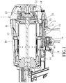
- the pneumatic tool 1 includes a casing 10 that defines a main chamber 11 and an operating chamber 12 therein, a valve head 13 that is movable within the casing 10, a safety member 14 that is movably mounted to the casing 10, a trigger assembly 15 that is pivotally mounted to the casing 10, an actuating valve 16, and a cylinder body 17.
- the main chamber 11 is continuously supplied with compressed air by an air source.
- the valve head 13 is disposed between the main chamber 11 and the operating chamber 12, and removably seals the cylinder body 17.
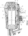
- the actuating valve 16 includes a valve rod 161 that is movable relative to the casing 10 between an activated position (see Figure 4 ) where both of the trigger assembly 15 and the safety member 14 are depressed, and a non-activated position (see Figure 1 ) where the trigger assembly 15 and the safety member 14 are not simultaneously depressed.
- the valve rod 161 When the valve rod 161 is at the non-activated position, the operating chamber 12 is permitted to communicate fluidly with the main chamber 11 via an inner flow path and is prevented from communicating fluidly with the outside, so that the pressure in the operating chamber 12 is the same as that in the main chamber 11, and the valve head 13 is therefore maintained to seal the cylinder body 17.
- the operating chamber 12 When the valve rod 161 is at the activated position, the operating chamber 12 is prevented from communicating fluidly with the main chamber 11 via the inner flow path and is permitted to communicate fluidly with the outside, so that the pressure in the operating chamber 12 is much smaller than that in the main chamber 11, and the valve head 13 is therefore moved to open the cylinder body 17 due to the pressure difference between the main chamber 11 and the operating chamber 12, so as to permit the compressed air in the main chamber 11 to flow into the cylinder body 17 for firing a fastener.
- the fastener can be fired by the pneumatic tool 1 by continuously depressing the trigger assembly 15 and subsequently depressing the safety member 14 to activate the valve rod 161.
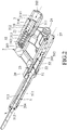
- the first embodiment of the firing control device includes a flow path unit 2, a conditioning valve assembly 3, a throttle valve unit 4 and a switch valve assembly 5.
- the flow path unit 2 includes a casing seat 20, a first passage 21 that is formed in the casing seat 20 and that is in fluid communication with the main chamber 11, a second passage 22 that is parallel to the first passage 21, a connecting passage 23 that is in fluid communication with the first and second passages 21, 22, an inflation passage 24 that is in fluid communication with the first passage 21 and the operating chamber 12, and a one-way valve unit 26.
- the casing seat 20 has a lateral opening 201 that communicates fluidly the main chamber 11 with an intermediate section of the first passage 21, a first end opening 202 that communicates fluidly the main chamber 11 with a first lengthwise end section of the first passage 21, a communicating hole 203 that communicates fluidly the connecting passage 23 with a second lengthwise end section of the first passage 21 that is opposite to the first lengthwise end section of the first passage 21, and a second end opening 27 that communicates fluidly a first lengthwise end section of the second passage 22 with either one of the main chamber 11 and the operating chamber 12.
- the second passage 22 has first and second shrunk sections 204, 205 that are spaced apart from each other in the lengthwise direction of the second passage 22.
- the connecting passage 23 is in fluid communication with an intermediate section of the second passage 22 that is located between the first and second shrunk sections 204, 205.
- the first shrunk section 204 is located between the intermediate section of the second passage 22 and a second lengthwise end section of the second passage 22 that is distal from the second end opening 27 and that communicates fluidly with the outside.
- the second shrunk section 205 is located between the intermediate section of the second passage 22 and the second end opening 27.
- the inflation passage 24 is in fluid communication with the intermediate section of the first passage 21.
- the one-way valve unit 26 is capable of fluidly communicating the first lengthwise end section of the second passage 22 with the inflation passage 24, and permits the air to flow from the second passage 22 into the inflation passage 24 only.
- the conditioning valve assembly 3 includes a conditioning valve 31 that is movable along the first passage 21, and a conditioning resilient member 32.
- the conditioning valve 31 includes a valve body 311, and three conditioning sealing rings 312 that are sleeved on the valve body 311 and that are spaced apart from each other.
- the conditioning sealing rings 312 are in air-tight contact with an inner surrounding surface of the casing seat 20 that defines the first passage 21, and cooperatively define first and second annular gaps 313, 314 that are not in fluid communication with each other (each of the first and second annular gaps 313, 314 is defined between two adjacent ones of the conditioning sealing rings 312).
- the valve body 311 has an end surface 3111 that faces toward the first end opening 202.
- the conditioning valve 31 is movable relative to the casing seat 20 between an initial position (see Figures 2 and 3 ) and an ultimate position (see Figures 5 and 6 ).
- the main chamber 11 When the conditioning valve 31 is at the ultimate position, the main chamber 11 is in fluid communication with the first annular gap 313 via the lateral opening 201, and the operating chamber 12 is in fluid communication with the first annular gap 313 via the inflation passage 24, so that the main chamber 11 and the operating chamber 12 are in fluid communication with each other via the first passage 21 and the inflation passage 24.
- the main chamber 11 When the conditioning valve 31 leaves the ultimate position, the main chamber 11 is in fluid communication with the second annular gap 314 via the lateral opening 201, and the operating chamber 12 is in fluid communication with the first annular gap 313 via the inflation passage 24, so that the main chamber 11 and the operating chamber 12 cannot fluidly communicate with each other via the first passage 21 since the first and second annular gaps 313, 314 are not in fluid communication with each other (i.e., the fluid communication between the main chamber 11 and the operating chamber 12 is blocked).
- the conditioning resilient member 32 is disposed in the first passage 21, and resiliently biases the conditioning valve 31 toward the ultimate position.
- the throttle valve unit 4 is disposed in the casing 10, and is connected between the second end opening 27 and the one of the main chamber 11 and the operating chamber 12 for adjusting the flow rate of the air flowing into the second passage 22 via the second end opening 27 from the one of the main chamber 11 and the operating chamber 12.
- the switch valve assembly 5 includes a switch valve 51 and a switch resilient member 52.
- the switch valve 51 includes a rod body 511, and two switch sealing rings 512 that are sleeved on the rod body 511 and that are spaced apart from each other.
- Each of the switch sealing rings 512 is operable to be in air-tight contact with a respective one of first and second additional inner surrounding surfaces of the casing seat 20 that respectively define the first and second shrunk sections 204, 205 of the second passage 22.
- the switch sealing rings 512 cooperatively define a switch annular gap 513 therebetween. A distance between the switch sealing rings 512 is different from that between the first and second shrunk sections 204, 205 of the second passage 22.
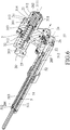
- the switch valve 51 is movable relative to the casing seat 20 between a non-activated position (see Figures 1 to 3 ) where the trigger assembly 15 is not depressed, and an activated position (see Figures 4 to 6 ) where the trigger assembly 15 is depressed.
- one of the switch sealing rings 512 When the switch valve 51 is at the non-activated position, one of the switch sealing rings 512 is in air-tight contact with the second additional inner surrounding surface of the casing seat 20 that defines the second shrunk section 205, and the other one of the switch sealing rings 512 is separated from the first additional inner surrounding surface of the casing seat 20 that defines the first shrunk section 204, so that the connecting passage 23 is in fluid communication with the outside via the intermediate section of the second passage 22 (the switch annular gap 513 is in fluid communication with the outside), and is not in fluid communication with the one of the main chamber 11 and the operating chamber 12 that is in fluid communication with the throttle valve unit 4.
- the switch valve 51 When the switch valve 51 is at the activated position upon the depression of the trigger assembly 15 (see Figure 4 ), the one of the switch sealing rings 512 is separated from the second additional inner surrounding surface of the casing seat 20 that defines the second shrunk section 205, and the other one of the switch sealing rings 512 is in air-tight contact with the first additional inner surrounding surface of the casing seat 20 that defines the first shrunk section 204, so that the connecting passage 23 is not in fluid communication with the outside (the switch annular gap 513 is not in fluid communication with the outside), and is in fluid communication with the one of the main chamber 11 and the operating chamber 12 via the throttle valve unit 4.
- the switch resilient member 52 is disposed in the second passage 22, and resiliently biases the switch valve 51 toward the non-activated position.
- the switch valve 51 when the trigger assembly 15 is not depressed, the switch valve 51 is at the non-activated position, so that the connecting passage 23 is in fluid communication with the outside via the intermediate section of the second passage 22, and is not in fluid communication with the one of the main chamber 11 and the operating chamber 12 via the throttle valve unit 4.
- the pressure in the main chamber 11 acts on the end surface 3111 of the conditioning valve 31 via the first end opening 202 to generate a first resultant force to move the conditioning valve 31 to the initial position against the biasing action of the conditioning resilient member 32 since the pressure in the connecting passage 23 is relatively low (substantially equal to the outside), and the fluid communication between the main chamber 11 and the operating chamber 12 via the first passage 21 and the inflation passage 24 is therefore prevented.
- a fastener can be fired by the pneumatic tool 1 by continuously depressing the trigger assembly 15 and subsequently depressing the safety member 14 to activate the valve rod 161 of the actuating valve 16.
- the pressure in the one of the main chamber 11 and the operating chamber 12 acts on one side of the conditioning valve 31 opposite to the end surface 3111 via the throttle valve unit 4, the second passage 22 and the connecting passage 23 to generate a second resultant force that has a direction which is substantially opposite to the first resultant force generated by the pressure in the main chamber 11.
- the sum of the second resultant force and the biasing force generated by the conditioning resilient member 32 is greater than the first resultant force, so that the conditioning valve 31 is moved toward the ultimate position upon continuous depression of the trigger assembly 15.
- the conditioning valve 31 is moved by the second resultant force and the biasing force generated by the conditioning resilient member 32 to the ultimate position so as to permit the fluid communication between the main chamber 11 and the operating chamber 12 via the first passage 21 and the inflation passage 24.
- a predetermined time period e.g., 3 to 5 seconds
- the switch valve 51 is continuously activated by the predetermined time period
- the conditioning valve 31 is moved by the second resultant force and the biasing force generated by the conditioning resilient member 32 to the ultimate position so as to permit the fluid communication between the main chamber 11 and the operating chamber 12 via the first passage 21 and the inflation passage 24.
- the predetermined time period is adjustable by virtue of the throttle valve unit 4.
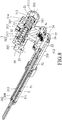
- valve rod 161 for firing the fastener, when a time delay between the depression of the trigger assembly 15 and the depression of the safety member 14 is less than the predetermined time period, the valve rod 161 is activated upon the depression of the safety member 14 before the conditioning valve 31 is moved to the ultimate position. Therefore, the fluid communication between the main chamber 11 and the operating chamber 12 via the first passage 21 and the inflation passage 24 is prevented, and the valve head 13 is therefore moved to open the cylinder body 17 due to the pressure difference between the main chamber 11 and the operating chamber 12 (the operating chamber 12 is in fluid communication with the outside when the valve rod 161 is activated), so as to permit the compressed air in the main chamber 11 to flow into the cylinder body 17 for firing the fastener.
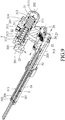
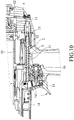
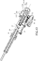
- the first resultant force generated by the pressure in the main chamber 11 moves the conditioning valve 31 back to the initial position against the biasing action of the conditioning resilient member 32. Therefore, with the trigger assembly 15 being continuously depressed (see Figure 10 ), the safety member 14 can be depressed again to fire another fastener when the time delay between two successive depressions of the safety member 14 is less than the predetermined time period.
- the air in the second lengthwise end section of the first passage 21 is forced to flow into the second passage 22 via the communicating hole 203 and the connecting passage 23, and then to flow into the operating chamber 12 via the one-way valve unit 26 and the inflation passage 24.
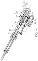
- the conditioning valve 31 is moved to the ultimate position to permit the fluid communication between the main chamber 11 and the operating chamber 12 via the first passage 21 and the inflation passage 24 before the valve rod 161 is activated. Therefore, when the valve rod 161 is activated upon the depression of the safety member 14 to permit the fluid communication between the operating chamber 12 and the outside for firing the fastener, the pressure difference between the main chamber 11 and the operating chamber 12 is insufficient to move the valve head 13 to open the cylinder body 17 since the compressed air in the main chamber 11 continuously flows into the operating chamber 12 via the first passage 21 and the inflation passage 24, and the firing of the fastener is therefore prevented.
- the trigger assembly 15 can be released such that the switch valve 51 is moved back to non-activated position by the switch resilient member 52 to permit the fluid communication between the connecting passage 23 and the outside via the intermediate section of the second passage 22, and to prevent the fluid communication between the connecting passage 23 and the one of the main chamber 11 and the operating chamber 12 via the throttle valve unit 4, and that the conditioning valve 31 is therefore moved back to the initial position by the first resultant force generated by the pressure in the main chamber 11 against the biasing action of the conditioning resilient member 32.
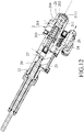
- the second embodiment of the firing control device is similar to the first embodiment.
- the differences between the first and second embodiments reside in that the first and second passages 21, 22 of the second embodiment are aligned with each other, the connecting passage 23 of the second embodiment is U-shaped, and the one-way valve unit 26 of the second embodiment is capable of fluidly communicating the connecting passage 23 with the inflation passage 24 and permits the air to flow from the connecting passage 23 into the inflation passage 24 only.
- a distance between the one-way valve unit 26 and the second lengthwise end section of the first passage 21 is smaller than that of the first embodiment.
- the throttle valve unit (not shown) of the second embodiment is connected between the second end opening 27 and the one of the main chamber 11 and the operating chamber 12 (referring to Figure 1 ) for adjusting the flow rate of the air flowing into the second passage 22 via the second end opening 27 from the one of the main chamber 11 and the operating chamber 12.
- the operation of the second embodiment is similar to that of the first embodiment.
- the throttle valve unit of the second embodiment communicates fluidly the second end opening 27 with the main chamber 11 (referring to Figure 1 )
- the air in the second lengthwise end section of the first passage 21 is forced to flow into the connecting passage 23 via the communicating hole 203, and then to flow into the operating chamber 12 via the one-way valve unit 26 and the inflation passage 24.
Landscapes
- Engineering & Computer Science (AREA)
- Mechanical Engineering (AREA)
- Physics & Mathematics (AREA)
- Fluid Mechanics (AREA)
- Multiple-Way Valves (AREA)
- Portable Nailing Machines And Staplers (AREA)
- Details Of Spanners, Wrenches, And Screw Drivers And Accessories (AREA)
Claims (16)
- Schießsteuerungsvorrichtung zur Verwendung in einem Druckluftwerkzeug (1), wobei das Druckluftwerkzeug (1) ein Gehäuse (10) aufweist, das eine Hauptkammer (11) und eine Bedienungskammer (12) darin definiert, ein Sicherheitselement (14), das am Gehäuse (10) beweglich montiert ist, eine Auslöseranordnung (15), die schwenkbar am Gehäuse (10) montiert ist, und eine Ventilstange (161), die relativ zum Gehäuse (10) beweglich ist, aufweist, wenn sowohl das Sicherheitselement (14) als auch die Auslöseranordnung (15) gedrückt werden, wobei die Ventilstange (161) aktiviert wird, um eine Fluidverbindung zwischen der Hauptkammer (11) und der Bedienungskammer (12) zu verhindern und den Druck in der Bedienungskammer (12) freizugeben, um ein Befestigungselement abzuschießen, wobei die Schießsteuerungsvorrichtung gekennzeichnet ist durch:eine Strömungswegeinheit (2), die geeignet ist, mit der Hauptkammer (11), der Bedienungskammer (12) und der Außenseite des Druckluftwerkzeugs (1) verbunden zu werden;eine Konditionierungsventilanordnung (3) mit einem Konditionierungsventil (31), das in der Strömungswegeinheit (2) beweglich angeordnet ist, und das die Fluidverbindung zwischen der Hauptkammer (11) und der Bedienungskammer (12) über die Strömungswegeinheit (2) entfernbar sperrt; undeine Umschaltventilanordnung (5) mit einem Umschaltventil (51), das in der Strömungswegeinheit (2) beweglich angeordnet ist, wobei das Umschaltventil (51) beim Drücken der Auslöseranordnung (15) aktiviert wird, um eine Fluidverbindung zwischen der Strömungswegeinheit (2) und der Außenseite zu verhindern und zu ermöglichen, dass der Druck im Gehäuse (10) das Konditionierungsventil (31) bewegt, wobei das Konditionierungsventil (31) bewegt wird, um die Fluidverbindung zwischen der Hauptkammer (11) und der Bedienungskammer (12) über die Strömungswegeinheit (2) zu ermöglichen, wenn das Schaltventil (51) kontinuierlich durch eine vorbestimmte Zeitspanne aktiviert wird, so dass die Fluidverbindung zwischen der Hauptkammer (11) und der Bedienungskammer (12) bei der Aktivierung der Ventilstange (161) erhalten bleibt und das Schießen des Befestigungselements verhindert wird.
- Schießsteuerungsvorrichtung nach Anspruch 1, dadurch gekennzeichnet, dass die Strömungswegeinheit (2) einen ersten Durchgang (21) aufweist, der in Fluidverbindung mit der Hauptkammer (11) steht und das Konditionierungsventil (31) darin aufnimmt, einen zweiten Durchgang (22), der mit dem ersten Durchgang (21) und der Außenseite verbunden ist und das Schaltventil (51) darin aufnimmt, und einen Aufpumpdurchgang (24), der in Fluidverbindung mit dem ersten Durchgang (21) und der Bedienungskammer (12) steht und dazu dient, über den ersten Durchgang (21) einen Luftstrom von der Hauptkammer (11) zur Bedienungskammer (12) zu leiten.
- Schießsteuerungsvorrichtung nach Anspruch 2, ferner dadurch gekennzeichnet, dass die Strömungswegeinheit (2) ferner einen Verbindungsdurchgang (23) aufweist, der mit dem ersten und dem zweiten Durchgang (21, 22) in Fluidverbindung steht, und eine zweite Endöffnung (27) aufweist, durch die der zweite Durchgang (22) geeignet ist, in Fluidverbindung mit der Bedienungskammer (12) zu stehen, wenn das Schaltventil (51) aktiviert wird, wobei der Druck in der Bedienungskammer (12) über die zweite Endöffnung (27) auf das Konditionierungsventil (31), den zweiten Durchgang (22) und den Verbindungsdurchgang (23) wirkt, um das Konditionierungsventil (31) zu bewegen, damit die Fluidverbindung zwischen der Hauptkammer (11) und der Bedienungskammer (12) über den ersten Durchgang (21) und den Aufpumpdurchgang (24) ermöglicht wird.
- Schießsteuerungsvorrichtung nach Anspruch 3, ferner dadurch gekennzeichnet, dass die Schaltventilanordnung (5) ferner ein robustes Schalterelement (52) aufweist, wobei das Schaltventil (51) relativ zur Strömungswegeinheit (2) zwischen einer nicht aktivierten Position und einer aktivierten Position beweglich ist, wenn sich das Schaltventil (51) in nicht aktivierter Position befindet, wobei der Verbindungsdurchgang (23) über den zweiten Durchgang (22) in Fluidverbindung mit der Außenseite steht, und nicht in Fluidverbindung mit der Bedienungskammer (12), wenn sich das Schaltventil (51) in aktivierter Position befindet, wobei der Verbindungsdurchgang (23) nicht in Fluidverbindung mit der Außenseite steht und über die zweite Endöffnung (27) und den zweiten Durchgang (22) in Fluidverbindung mit der Bedienungskammer (12) steht, wobei das robuste Schalterelement (52) im zweiten Durchgang (22) angeordnet ist, und das Schaltventil (51) kräftig in Richtung der nicht aktivierten Position vorgespannt wird.
- Schießsteuerungsvorrichtung nach Anspruch 4, ferner dadurch gekennzeichnet, dass das Schaltventil (51) einen Stangenkörper (511) und zwei Schalterdichtringe (512) aufweist, die auf den Stangenkörper (511) aufgesteckt sind, und die zusammenwirkend einen Schalterringspalt (513) dazwischen definieren, wobei der Schalterringspalt (513) in Fluidverbindung mit dem Verbindungsdurchgang (23) steht, wenn sich das Schaltventil (51) in nicht aktivierter Position befindet, wobei der Schalterringspalt (513) in Fluidverbindung mit der Außenseite steht, und einer der Schalterdichtringe (512) den zweiten Durchgang (22) abdichtet, um die Fluidverbindung zwischen dem Schalterringspalt (513) und der Bedienungskammer (12) zu verhindern, wenn sich das Schaltventil (51) in aktivierter Position befindet, wobei der Schalterringspalt (513) in Fluidverbindung mit der Bedienungskammer (12) steht, und der andere der Schalterdichtringe (512) den zweiten Durchgang (22) abdichtet, um die Fluidverbindung zwischen dem Schalterringspalt (513) und der Außenseite zu verhindern.
- Schießsteuerungsvorrichtung nach Anspruch 2, ferner dadurch gekennzeichnet, dass die Strömungswegeinheit (2) ferner einen Verbindungsdurchgang (23) aufweist, der in Fluidverbindung mit dem ersten und zweiten Durchgang (21, 22) steht, und eine zweite Endöffnung (27) aufweist, durch die der zweite Durchgang (22) geeignet ist, in Fluidverbindung mit der Hauptkammer (11) zu stehen, wenn das Schaltventil (51) aktiviert ist, wobei der Druck in der Hauptkammer (11) über die zweite Endöffnung (27) auf das Konditionierungsventil (31), den zweiten Durchgang (22) und den Verbindungsdurchgang (23) wirkt, um das Konditionierungsventil (31) zu bewegen, damit die Fluidverbindung zwischen der Hauptkammer (11) und der Bedienungskammer (12) über den ersten Durchgang (21) und den Aufpumpdurchgang (24) ermöglicht wird.
- Schießsteuerungsvorrichtung nach Anspruch 6, ferner dadurch gekennzeichnet, dass die Schaltventilanordnung (5) ferner ein robustes Schalterelement (52) aufweist, wobei das Schaltventil (51) relativ zur Strömungswegeinheit (2) zwischen einer nicht aktivierten Position und einer aktivierten Position beweglich ist, wenn sich das Schaltventil (51) in nicht aktivierter Position befindet, wobei der Verbindungsdurchgang (23) über den zweiten Durchgang (22) in Fluidverbindung mit der Außenseite steht, und nicht in Fluidverbindung mit der Hauptkammer (11), wenn sich das Schaltventil (51) in aktivierter Position befindet, wobei der Verbindungsdurchgang (23) nicht in Fluidverbindung mit der Außenseite steht und über die zweite Endöffnung (27) und den zweiten Durchgang (22) in Fluidverbindung mit der Hauptkammer (12) steht, wobei das robuste Schalterelement (52) im zweiten Durchgang (22) angeordnet ist, und das Schaltventil (51) kräftig in Richtung der nicht aktivierten Position vorgespannt wird.
- Schießsteuerungsvorrichtung nach Anspruch 7, ferner dadurch gekennzeichnet, dass das Schaltventil (51) einen Stangenkörper (511) und zwei Schalterdichtringe (512) aufweist, die auf den Stangenkörper (511) aufgesteckt sind, und die zusammenwirkend einen Schalterringspalt (513) dazwischen definieren, wobei der Schalterringspalt (513) in Fluidverbindung mit dem Verbindungsdurchgang (23) steht, wenn sich das Schaltventil (51) in nicht aktivierter Position befindet, wobei der Schalterringspalt (513) in Fluidverbindung mit der Außenseite steht, und einer der Schalterdichtringe (512) den zweiten Durchgang (22) abdichtet, um die Fluidverbindung zwischen dem Schalterringspalt (513) und der Hauptkammer (11) zu verhindern, wenn sich das Schaltventil (51) in aktivierter Position befindet, wobei der Schalterringspalt (513) in Fluidverbindung mit der Hauptkammer (11) steht, und der andere der Schalterdichtringe (512) den zweiten Durchgang (22) abdichtet, um die Fluidverbindung zwischen dem Schalterringspalt (513) und der Außenseite zu verhindern.
- Schießsteuerungsvorrichtung nach Anspruch 3, ferner durch eine Drosselklappeneinheit (4) gekennzeichnet, die geeignet ist, im Gehäuse (10) angeordnet zu werden, und die zwischen der zweiten Endöffnung (27) und der Bedienungskammer (12) verbunden ist, um den Durchsatz der aus der Bedienungskammer (12) über die zweite Endöffnung (27) in den zweiten Durchgang (22) strömenden Luft einzustellen.
- Schießsteuerungsvorrichtung nach Anspruch 3, ferner dadurch gekennzeichnet, dass die Konditionierungsventilanordnung (3) ferner ein konditionierendes robustes Element (32) aufweist, wobei das Konditionierungsventil (31) relativ zur Strömungswegeinheit (2) zwischen einer Ausgangsposition und einer Endposition beweglich ist, wobei die Fluidverbindung zwischen der Hauptkammer (11) und der Bedienungskammer (12) über den ersten Durchgang (21) und den Aufpumpdurchgang (24) zulässig ist, wenn sich das Konditionierungsventil (31) in der Endposition befindet, die Fluidverbindung zwischen der Hauptkammer (11) und der Bedienungskammer (12) über den ersten Durchgang (21) und den Aufpumpdurchgang (24) verhindert wird, wenn das Konditionierungsventil (31) von der Endposition entfernt ist, wobei das konditionierende robuste Element (32) im ersten Durchgang (21) angeordnet ist, und das Konditionierungsventil (31) kräftig in Richtung der Endposition vorgespannt wird.
- Schießsteuerungsvorrichtung nach Anspruch 10, ferner dadurch gekennzeichnet, dass das Konditionierungsventil (31) einen Ventilkörper (311) und drei auf den Ventilkörper (311) aufgesetzte und voneinander beabstandete Konditionierungsdichtringe (312) aufweist, wobei die Konditionierungsdichtringe (312) zusammenwirkend erste und zweite Ringspalte (313, 314) definieren, die nicht in Fluidverbindung miteinander stehen, wenn sich das Konditionierungsventil (31) in der Endposition befindet, wobei die Hauptkammer (11) in Fluidverbindung mit dem ersten Ringspalt (313) steht, und die Bedienungskammer (12) über den Aufpumpdurchgang (24) in Fluidverbindung mit dem ersten Ringspalt (313) steht, so dass sie in Fluidverbindung mit der Hauptkammer (11) steht, wenn das Konditionierungsventil (31) die Endposition verlässt, wobei die Hauptkammer (11) in Fluidverbindung mit dem zweiten Ringspalt (314) steht und die Bedienungskammer (12) über den Aufpumpdurchgang (24) in Fluidverbindung mit dem ersten Ringspalt (313) steht, um nicht in Fluidverbindung mit der Hauptkammer (11) zu stehen.
- Schießsteuerungsvorrichtung nach Anspruch 11, ferner dadurch gekennzeichnet, dass die Strömungswegeinheit (2) ferner einen Gehäusesitz (20) aufweist, der mit dem ersten Durchgang (21), dem zweiten Durchgang (22), dem Verbindungsdurchgang (23) und dem Aufpumpdurchgang (24) ausgebildet ist, wobei der Gehäusesitz (20) eine seitliche Öffnung (201) aufweist, die die Hauptkammer (11) mit einem Zwischenabschnitt des ersten Durchgangs (21) fluidisch verbindet, eine erste Endöffnung (202), die die Hauptkammer (11) mit einem ersten Längsendabschnitt des ersten Durchgangs (21) fluidisch verbindet, wobei der Ventilkörper (311) des Konditionierungsventils (31) eine Endfläche (3111) aufweist, die der ersten Endöffnung (202) zugewandt ist, wobei der Druck in der Hauptkammer (11) über die erste Endöffnung (202) auf die Endfläche (3111) des Konditionierungsventils (31) wirkt.
- Schießsteuerungsvorrichtung nach Anspruch 6, ferner durch eine Drosselklappeneinheit (4) gekennzeichnet, die geeignet ist, im Gehäuse (10) angeordnet zu werden, und die zwischen der zweiten Endöffnung (27) und der Hauptkammer (11) verbunden ist, um den Durchsatz der aus der Hauptkammer (11) über die zweite Endöffnung (27) in den zweiten Durchgang (22) strömenden Luft einzustellen.
- Schießsteuerungsvorrichtung nach Anspruch 6, ferner dadurch gekennzeichnet, dass die Konditionierungsventilanordnung (3) ferner ein konditionierendes robustes Element (32) aufweist, wobei das Konditionierungsventil (31) relativ zu der Strömungswegeinheit (2) zwischen einer Ausgangsposition und einer Endposition beweglich ist, wobei die Fluidverbindung zwischen der Hauptkammer (11) und der Bedienungskammer (12) über den ersten Durchgang (21) und den Aufpumpdurchgang (24) verhindert wird, wenn sich das Konditionierungsventil (31) in der Ausgangsposition befindet, die Fluidverbindung zwischen der Hauptkammer (11) und der Bedienungskammer (12) über den ersten Durchgang (21) und den Aufpumpdurchgang (24) zulässig ist, wenn das Konditionierungsventil (31) an der Endposition ist, wobei das konditionierende robuste Element (32) im ersten Durchgang (21) angeordnet ist und das Konditionierungsventil (31) kräftig in Richtung der Endposition vorgespannt ist.
- Schießsteuerungsvorrichtung nach Anspruch 14, ferner dadurch gekennzeichnet, dass das Konditionierungsventil (31) einen Ventilkörper (311) und drei auf den Ventilkörper (311) aufgesetzte und voneinander beabstandete Konditionierungsdichtringe (312) aufweist, wobei die Konditionierungsdichtringe (312) zusammenwirkend erste und zweite Ringspalte (313, 314) definieren, die nicht in Fluidverbindung miteinander stehen, wenn sich das Konditionierungsventil (31) in der Endposition befindet, wobei die Hauptkammer (11) in Fluidverbindung mit dem ersten Ringspalt (313) steht, und die Bedienungskammer (12) über den Aufpumpdurchgang (24) in Fluidverbindung mit dem ersten Ringspalt (313) steht, so dass sie in Fluidverbindung mit der Hauptkammer (11) steht, wenn das Konditionierungsventil (31) die Endposition verlässt, wobei die Hauptkammer (11) in Fluidverbindung mit dem zweiten Ringspalt (314) steht und die Bedienungskammer (12) über den Aufpumpdurchgang (24) in Fluidverbindung mit dem ersten Ringspalt (313) steht, um nicht in Fluidverbindung mit der Hauptkammer (11) zu stehen.
- Schießsteuerungsvorrichtung nach Anspruch 15, ferner dadurch gekennzeichnet, dass die Strömungswegeinheit (2) ferner einen Gehäusesitz (20) aufweist, der mit dem ersten Durchgang (21), dem zweiten Durchgang (22), dem Verbindungsdurchgang (23) und dem Aufpumpdurchgang (24) ausgebildet ist, wobei der Gehäusesitz (20) eine seitliche Öffnung (201) aufweist, die die Hauptkammer (11) mit einem Zwischenabschnitt des ersten Durchgangs (21) fluidisch verbindet, eine erste Endöffnung (202), die die Hauptkammer (11) mit einem ersten Längsendabschnitt des ersten Durchgangs (21) fluidisch verbindet, wobei der Ventilkörper (311) des Konditionierungsventils (31) eine Endfläche (3111) aufweist, die der ersten Endöffnung (202) zugewandt ist, wobei der Druck in der Hauptkammer (11) über die erste Endöffnung (202) auf die Endfläche (3111) des Konditionierungsventils (31) wirkt.
Applications Claiming Priority (1)
| Application Number | Priority Date | Filing Date | Title |
|---|---|---|---|
| TW105108409A TWI696527B (zh) | 2016-03-18 | 2016-03-18 | 氣動工具的安全性擊發控制裝置 |
Publications (3)
| Publication Number | Publication Date |
|---|---|
| EP3263284A2 EP3263284A2 (de) | 2018-01-03 |
| EP3263284A3 EP3263284A3 (de) | 2018-05-16 |
| EP3263284B1 true EP3263284B1 (de) | 2019-05-22 |
Family
ID=58387668
Family Applications (1)
| Application Number | Title | Priority Date | Filing Date |
|---|---|---|---|
| EP17161407.6A Active EP3263284B1 (de) | 2016-03-18 | 2017-03-16 | Feuerungssteuerungsvorrichtung für ein pneumatisches werkzeug |
Country Status (3)
| Country | Link |
|---|---|
| US (1) | US10335936B2 (de) |
| EP (1) | EP3263284B1 (de) |
| TW (1) | TWI696527B (de) |
Families Citing this family (7)
| Publication number | Priority date | Publication date | Assignee | Title |
|---|---|---|---|---|
| EP3473385A1 (de) * | 2017-10-18 | 2019-04-24 | Joh. Friedrich Behrens AG | Druckluftnagler mit einem sicherheitsstellglied |
| US11065749B2 (en) | 2018-03-26 | 2021-07-20 | Tti (Macao Commercial Offshore) Limited | Powered fastener driver |
| PL3760379T3 (pl) * | 2019-07-02 | 2022-03-21 | Bea Gmbh | Pneumatyczna gwoździarka z urządzeniem zabezpieczającym |
| TW202103864A (zh) | 2019-07-30 | 2021-02-01 | 鑽全實業股份有限公司 | 氣動工具的節流閥 |
| JP7435310B2 (ja) * | 2020-06-30 | 2024-02-21 | マックス株式会社 | 空気圧工具 |
| JP7435312B2 (ja) * | 2020-06-30 | 2024-02-21 | マックス株式会社 | 空気圧工具 |
| JP7435311B2 (ja) * | 2020-06-30 | 2024-02-21 | マックス株式会社 | 空気圧工具 |
Family Cites Families (27)
| Publication number | Priority date | Publication date | Assignee | Title |
|---|---|---|---|---|
| US3498517A (en) * | 1967-04-21 | 1970-03-03 | Fastener Corp | Fastener driving tool |
| US3563438A (en) * | 1968-12-05 | 1971-02-16 | Fastener Corp | Fastener driving tool |
| US3583496A (en) * | 1969-02-19 | 1971-06-08 | Behrens Friedrich Joh | Compressed air-operated drive-in apparatus to drive-in fastening means such as nails, staples or the like |
| US3685396A (en) * | 1970-06-15 | 1972-08-22 | Fastener Corp | Fastener driving tool |
| DE2718942C3 (de) * | 1977-04-28 | 1980-02-14 | Senco Products, Inc., Cincinnati, Ohio (V.St.A.) | Auslösesicherung an einem Druckluftnagler |
| JPS601153B2 (ja) * | 1979-02-28 | 1985-01-12 | マックス株式会社 | 空気圧駆動型打撃工具における安全装置 |
| US4550643A (en) * | 1984-05-02 | 1985-11-05 | Duo-Fast Corporation | Fastener driving tool |
| US4784308A (en) * | 1986-04-03 | 1988-11-15 | Duo-Fast Corporation | Fastener driving tool |
| DE8801114U1 (de) * | 1988-01-30 | 1988-03-31 | Joh. Friedrich Behrens AG, 2070 Ahrensburg | Steuerventileinrichtung an einem mit Druckluft betriebenen Gerät zum Eintreiben von Befestigungsmitteln |
| DE9216386U1 (de) * | 1992-12-02 | 1993-02-11 | Joh. Friedrich Behrens AG, 2070 Ahrensburg | Steuerventileinrichtung |
| DE9305760U1 (de) * | 1993-04-16 | 1993-06-17 | Joh. Friedrich Behrens AG, 2070 Ahrensburg | Auslösesicherung an einem Eintreibgerät für Befestigungsmittel |
| US5522532A (en) | 1995-03-14 | 1996-06-04 | Testo Industry Corp. | Single-shooting/continuous-shooting control switch for penumatic nail guns |
| IT1279670B1 (it) * | 1995-11-02 | 1997-12-16 | Fasco Spa | Fissatrice ad aria compressa a valvola in testa funzionante a colpo singolo e a ripetizione. |
| US5896933A (en) * | 1995-11-16 | 1999-04-27 | Stanley Fastening Systems, L.P. | Fastener driving device having interchangeable control modules |
| US5829660A (en) * | 1995-12-07 | 1998-11-03 | Stanley-Bostitch, Inc. | Automatic-type fastener driving device |
| US5669542A (en) * | 1996-05-17 | 1997-09-23 | Stanley-Bostitch, Inc. | Fastener driving device having full cycle valve |
| US6371348B1 (en) * | 1999-08-06 | 2002-04-16 | Stanley Fastening Systems, Lp | Fastener driving device with enhanced sequential actuation |
| US6745928B2 (en) * | 2000-01-24 | 2004-06-08 | Hitachi Co., Ltd | Trigger valve apparatus for pneumatic tool |
| JP4102998B2 (ja) * | 2003-09-10 | 2008-06-18 | マックス株式会社 | 釘打機の起動装置 |
| US7677426B2 (en) * | 2005-09-19 | 2010-03-16 | Stanley Fastening Systems, L.P. | Fastener driving device |
| TW200738408A (en) * | 2006-04-07 | 2007-10-16 | P & F Brother Ind Corp | Single triggering and continuous triggering converting device for nail punch |
| TW200740572A (en) * | 2006-04-17 | 2007-11-01 | Samson Power Tool Co Ltd | Serial switch structure for nail gun |
| US7556183B1 (en) * | 2008-02-04 | 2009-07-07 | De Poan Pneumatic Corp. | Control device for nail hitting of pneumatic nail guns |
| TWI404603B (zh) * | 2009-04-03 | 2013-08-11 | Basso Ind Corp | 具擊發保險裝置之打釘槍 |
| JP5585417B2 (ja) * | 2010-11-26 | 2014-09-10 | 日立工機株式会社 | 打込機 |
| ES2618859T3 (es) * | 2013-02-19 | 2017-06-22 | Joh. Friedrich Behrens Ag | Clavadora neumática con un disparador accionable manualmente y un sensor de contacto |
| TWM473908U (zh) * | 2013-10-04 | 2014-03-11 | Basso Ind Corp | 氣動釘槍之壓源控制裝置 |
-
2016
- 2016-03-18 TW TW105108409A patent/TWI696527B/zh not_active IP Right Cessation
-
2017
- 2017-03-15 US US15/459,050 patent/US10335936B2/en not_active Expired - Fee Related
- 2017-03-16 EP EP17161407.6A patent/EP3263284B1/de active Active
Non-Patent Citations (1)
| Title |
|---|
| None * |
Also Published As
| Publication number | Publication date |
|---|---|
| TWI696527B (zh) | 2020-06-21 |
| EP3263284A2 (de) | 2018-01-03 |
| US10335936B2 (en) | 2019-07-02 |
| EP3263284A3 (de) | 2018-05-16 |
| US20170266795A1 (en) | 2017-09-21 |
| TW201733746A (zh) | 2017-10-01 |
Similar Documents
| Publication | Publication Date | Title |
|---|---|---|
| EP3263284B1 (de) | Feuerungssteuerungsvorrichtung für ein pneumatisches werkzeug | |
| US4776561A (en) | Trigger control for air tool handle | |
| US4476942A (en) | Variable speed inlet control valve | |
| EP2812158B1 (de) | Hülse für ein pneumatisches eintreibwerkzeug | |
| US9844867B2 (en) | Cushion device for cylinder of pneumatic tool | |
| CN102959486A (zh) | 减压设备 | |
| EP3546128B1 (de) | Nagelpistole | |
| CN109843512A (zh) | 具有安全控制腔室的气动钉枪 | |
| US5257817A (en) | Air bag inflator having a ball piston valve assembly | |
| JP2016080007A (ja) | パイロットチェック弁 | |
| CN111225769B (zh) | 具有安全调节元件的气动钉枪 | |
| US20170361443A1 (en) | Cylindrical Integrated Valve Assembly | |
| US7475800B2 (en) | Trigger valve for pneumatic nail gun | |
| CN102135196A (zh) | 比例压力控制器 | |
| US4042178A (en) | Shutoff valve construction particularly for high pressure | |
| US20030222104A1 (en) | Continuously shooting pneumatic grease gun structure | |
| WO2015152338A1 (ja) | 減圧弁 | |
| JP2003519340A (ja) | 圧力ブースタ | |
| JPS60501020A (ja) | 制御バルブ | |
| KR20180137287A (ko) | 타이어 공기압 조절용 휠밸브 | |
| JP4564456B2 (ja) | 空気圧式往復動工具。 | |
| JPS6311431Y2 (de) | ||
| JP2005316988A (ja) | 圧力制御弁及び複数の出力口を備えた圧力制御弁ユニット | |
| US20180339407A1 (en) | Pneumatic tool | |
| CA1083462A (en) | Shuttle valve |
Legal Events
| Date | Code | Title | Description |
|---|---|---|---|
| PUAI | Public reference made under article 153(3) epc to a published international application that has entered the european phase |
Free format text: ORIGINAL CODE: 0009012 |
|
| STAA | Information on the status of an ep patent application or granted ep patent |
Free format text: STATUS: REQUEST FOR EXAMINATION WAS MADE |
|
| 17P | Request for examination filed |
Effective date: 20170316 |
|
| AK | Designated contracting states |
Kind code of ref document: A2 Designated state(s): AL AT BE BG CH CY CZ DE DK EE ES FI FR GB GR HR HU IE IS IT LI LT LU LV MC MK MT NL NO PL PT RO RS SE SI SK SM TR |
|
| AX | Request for extension of the european patent |
Extension state: BA ME |
|
| PUAL | Search report despatched |
Free format text: ORIGINAL CODE: 0009013 |
|
| AK | Designated contracting states |
Kind code of ref document: A3 Designated state(s): AL AT BE BG CH CY CZ DE DK EE ES FI FR GB GR HR HU IE IS IT LI LT LU LV MC MK MT NL NO PL PT RO RS SE SI SK SM TR |
|
| AX | Request for extension of the european patent |
Extension state: BA ME |
|
| RIC1 | Information provided on ipc code assigned before grant |
Ipc: B25C 1/00 20060101ALI20180411BHEP Ipc: B25C 1/04 20060101AFI20180411BHEP |
|
| GRAP | Despatch of communication of intention to grant a patent |
Free format text: ORIGINAL CODE: EPIDOSNIGR1 |
|
| STAA | Information on the status of an ep patent application or granted ep patent |
Free format text: STATUS: GRANT OF PATENT IS INTENDED |
|
| INTG | Intention to grant announced |
Effective date: 20181206 |
|
| RIN1 | Information on inventor provided before grant (corrected) |
Inventor name: LAI, CHUN-CHI |
|
| GRAS | Grant fee paid |
Free format text: ORIGINAL CODE: EPIDOSNIGR3 |
|
| GRAA | (expected) grant |
Free format text: ORIGINAL CODE: 0009210 |
|
| STAA | Information on the status of an ep patent application or granted ep patent |
Free format text: STATUS: THE PATENT HAS BEEN GRANTED |
|
| AK | Designated contracting states |
Kind code of ref document: B1 Designated state(s): AL AT BE BG CH CY CZ DE DK EE ES FI FR GB GR HR HU IE IS IT LI LT LU LV MC MK MT NL NO PL PT RO RS SE SI SK SM TR |
|
| REG | Reference to a national code |
Ref country code: GB Ref legal event code: FG4D |
|
| REG | Reference to a national code |
Ref country code: CH Ref legal event code: EP |
|
| REG | Reference to a national code |
Ref country code: IE Ref legal event code: FG4D |
|
| REG | Reference to a national code |
Ref country code: DE Ref legal event code: R096 Ref document number: 602017004039 Country of ref document: DE |
|
| REG | Reference to a national code |
Ref country code: AT Ref legal event code: REF Ref document number: 1135530 Country of ref document: AT Kind code of ref document: T Effective date: 20190615 |
|
| REG | Reference to a national code |
Ref country code: NL Ref legal event code: MP Effective date: 20190522 |
|
| REG | Reference to a national code |
Ref country code: LT Ref legal event code: MG4D |
|
| PG25 | Lapsed in a contracting state [announced via postgrant information from national office to epo] |
Ref country code: LT Free format text: LAPSE BECAUSE OF FAILURE TO SUBMIT A TRANSLATION OF THE DESCRIPTION OR TO PAY THE FEE WITHIN THE PRESCRIBED TIME-LIMIT Effective date: 20190522 Ref country code: HR Free format text: LAPSE BECAUSE OF FAILURE TO SUBMIT A TRANSLATION OF THE DESCRIPTION OR TO PAY THE FEE WITHIN THE PRESCRIBED TIME-LIMIT Effective date: 20190522 Ref country code: NL Free format text: LAPSE BECAUSE OF FAILURE TO SUBMIT A TRANSLATION OF THE DESCRIPTION OR TO PAY THE FEE WITHIN THE PRESCRIBED TIME-LIMIT Effective date: 20190522 Ref country code: NO Free format text: LAPSE BECAUSE OF FAILURE TO SUBMIT A TRANSLATION OF THE DESCRIPTION OR TO PAY THE FEE WITHIN THE PRESCRIBED TIME-LIMIT Effective date: 20190822 Ref country code: SE Free format text: LAPSE BECAUSE OF FAILURE TO SUBMIT A TRANSLATION OF THE DESCRIPTION OR TO PAY THE FEE WITHIN THE PRESCRIBED TIME-LIMIT Effective date: 20190522 Ref country code: FI Free format text: LAPSE BECAUSE OF FAILURE TO SUBMIT A TRANSLATION OF THE DESCRIPTION OR TO PAY THE FEE WITHIN THE PRESCRIBED TIME-LIMIT Effective date: 20190522 Ref country code: PT Free format text: LAPSE BECAUSE OF FAILURE TO SUBMIT A TRANSLATION OF THE DESCRIPTION OR TO PAY THE FEE WITHIN THE PRESCRIBED TIME-LIMIT Effective date: 20190922 Ref country code: AL Free format text: LAPSE BECAUSE OF FAILURE TO SUBMIT A TRANSLATION OF THE DESCRIPTION OR TO PAY THE FEE WITHIN THE PRESCRIBED TIME-LIMIT Effective date: 20190522 Ref country code: ES Free format text: LAPSE BECAUSE OF FAILURE TO SUBMIT A TRANSLATION OF THE DESCRIPTION OR TO PAY THE FEE WITHIN THE PRESCRIBED TIME-LIMIT Effective date: 20190522 |
|
| PG25 | Lapsed in a contracting state [announced via postgrant information from national office to epo] |
Ref country code: BG Free format text: LAPSE BECAUSE OF FAILURE TO SUBMIT A TRANSLATION OF THE DESCRIPTION OR TO PAY THE FEE WITHIN THE PRESCRIBED TIME-LIMIT Effective date: 20190822 Ref country code: GR Free format text: LAPSE BECAUSE OF FAILURE TO SUBMIT A TRANSLATION OF THE DESCRIPTION OR TO PAY THE FEE WITHIN THE PRESCRIBED TIME-LIMIT Effective date: 20190823 Ref country code: LV Free format text: LAPSE BECAUSE OF FAILURE TO SUBMIT A TRANSLATION OF THE DESCRIPTION OR TO PAY THE FEE WITHIN THE PRESCRIBED TIME-LIMIT Effective date: 20190522 Ref country code: RS Free format text: LAPSE BECAUSE OF FAILURE TO SUBMIT A TRANSLATION OF THE DESCRIPTION OR TO PAY THE FEE WITHIN THE PRESCRIBED TIME-LIMIT Effective date: 20190522 |
|
| REG | Reference to a national code |
Ref country code: AT Ref legal event code: MK05 Ref document number: 1135530 Country of ref document: AT Kind code of ref document: T Effective date: 20190522 |
|
| PG25 | Lapsed in a contracting state [announced via postgrant information from national office to epo] |
Ref country code: EE Free format text: LAPSE BECAUSE OF FAILURE TO SUBMIT A TRANSLATION OF THE DESCRIPTION OR TO PAY THE FEE WITHIN THE PRESCRIBED TIME-LIMIT Effective date: 20190522 Ref country code: DK Free format text: LAPSE BECAUSE OF FAILURE TO SUBMIT A TRANSLATION OF THE DESCRIPTION OR TO PAY THE FEE WITHIN THE PRESCRIBED TIME-LIMIT Effective date: 20190522 Ref country code: RO Free format text: LAPSE BECAUSE OF FAILURE TO SUBMIT A TRANSLATION OF THE DESCRIPTION OR TO PAY THE FEE WITHIN THE PRESCRIBED TIME-LIMIT Effective date: 20190522 Ref country code: AT Free format text: LAPSE BECAUSE OF FAILURE TO SUBMIT A TRANSLATION OF THE DESCRIPTION OR TO PAY THE FEE WITHIN THE PRESCRIBED TIME-LIMIT Effective date: 20190522 Ref country code: CZ Free format text: LAPSE BECAUSE OF FAILURE TO SUBMIT A TRANSLATION OF THE DESCRIPTION OR TO PAY THE FEE WITHIN THE PRESCRIBED TIME-LIMIT Effective date: 20190522 Ref country code: SK Free format text: LAPSE BECAUSE OF FAILURE TO SUBMIT A TRANSLATION OF THE DESCRIPTION OR TO PAY THE FEE WITHIN THE PRESCRIBED TIME-LIMIT Effective date: 20190522 |
|
| REG | Reference to a national code |
Ref country code: DE Ref legal event code: R097 Ref document number: 602017004039 Country of ref document: DE |
|
| PG25 | Lapsed in a contracting state [announced via postgrant information from national office to epo] |
Ref country code: SM Free format text: LAPSE BECAUSE OF FAILURE TO SUBMIT A TRANSLATION OF THE DESCRIPTION OR TO PAY THE FEE WITHIN THE PRESCRIBED TIME-LIMIT Effective date: 20190522 Ref country code: IT Free format text: LAPSE BECAUSE OF FAILURE TO SUBMIT A TRANSLATION OF THE DESCRIPTION OR TO PAY THE FEE WITHIN THE PRESCRIBED TIME-LIMIT Effective date: 20190522 |
|
| PLBE | No opposition filed within time limit |
Free format text: ORIGINAL CODE: 0009261 |
|
| STAA | Information on the status of an ep patent application or granted ep patent |
Free format text: STATUS: NO OPPOSITION FILED WITHIN TIME LIMIT |
|
| PG25 | Lapsed in a contracting state [announced via postgrant information from national office to epo] |
Ref country code: TR Free format text: LAPSE BECAUSE OF FAILURE TO SUBMIT A TRANSLATION OF THE DESCRIPTION OR TO PAY THE FEE WITHIN THE PRESCRIBED TIME-LIMIT Effective date: 20190522 |
|
| 26N | No opposition filed |
Effective date: 20200225 |
|
| PG25 | Lapsed in a contracting state [announced via postgrant information from national office to epo] |
Ref country code: PL Free format text: LAPSE BECAUSE OF FAILURE TO SUBMIT A TRANSLATION OF THE DESCRIPTION OR TO PAY THE FEE WITHIN THE PRESCRIBED TIME-LIMIT Effective date: 20190522 |
|
| PG25 | Lapsed in a contracting state [announced via postgrant information from national office to epo] |
Ref country code: SI Free format text: LAPSE BECAUSE OF FAILURE TO SUBMIT A TRANSLATION OF THE DESCRIPTION OR TO PAY THE FEE WITHIN THE PRESCRIBED TIME-LIMIT Effective date: 20190522 |
|
| PG25 | Lapsed in a contracting state [announced via postgrant information from national office to epo] |
Ref country code: MC Free format text: LAPSE BECAUSE OF FAILURE TO SUBMIT A TRANSLATION OF THE DESCRIPTION OR TO PAY THE FEE WITHIN THE PRESCRIBED TIME-LIMIT Effective date: 20190522 |
|
| REG | Reference to a national code |
Ref country code: CH Ref legal event code: PL |
|
| REG | Reference to a national code |
Ref country code: BE Ref legal event code: MM Effective date: 20200331 |
|
| PG25 | Lapsed in a contracting state [announced via postgrant information from national office to epo] |
Ref country code: LU Free format text: LAPSE BECAUSE OF NON-PAYMENT OF DUE FEES Effective date: 20200316 |
|
| PG25 | Lapsed in a contracting state [announced via postgrant information from national office to epo] |
Ref country code: LI Free format text: LAPSE BECAUSE OF NON-PAYMENT OF DUE FEES Effective date: 20200331 Ref country code: IE Free format text: LAPSE BECAUSE OF NON-PAYMENT OF DUE FEES Effective date: 20200316 Ref country code: CH Free format text: LAPSE BECAUSE OF NON-PAYMENT OF DUE FEES Effective date: 20200331 |
|
| PG25 | Lapsed in a contracting state [announced via postgrant information from national office to epo] |
Ref country code: BE Free format text: LAPSE BECAUSE OF NON-PAYMENT OF DUE FEES Effective date: 20200331 |
|
| PG25 | Lapsed in a contracting state [announced via postgrant information from national office to epo] |
Ref country code: MT Free format text: LAPSE BECAUSE OF FAILURE TO SUBMIT A TRANSLATION OF THE DESCRIPTION OR TO PAY THE FEE WITHIN THE PRESCRIBED TIME-LIMIT Effective date: 20190522 Ref country code: CY Free format text: LAPSE BECAUSE OF FAILURE TO SUBMIT A TRANSLATION OF THE DESCRIPTION OR TO PAY THE FEE WITHIN THE PRESCRIBED TIME-LIMIT Effective date: 20190522 |
|
| PG25 | Lapsed in a contracting state [announced via postgrant information from national office to epo] |
Ref country code: MK Free format text: LAPSE BECAUSE OF FAILURE TO SUBMIT A TRANSLATION OF THE DESCRIPTION OR TO PAY THE FEE WITHIN THE PRESCRIBED TIME-LIMIT Effective date: 20190522 Ref country code: IS Free format text: LAPSE BECAUSE OF FAILURE TO SUBMIT A TRANSLATION OF THE DESCRIPTION OR TO PAY THE FEE WITHIN THE PRESCRIBED TIME-LIMIT Effective date: 20190922 |
|
| PGFP | Annual fee paid to national office [announced via postgrant information from national office to epo] |
Ref country code: FR Payment date: 20230208 Year of fee payment: 7 |
|
| PGFP | Annual fee paid to national office [announced via postgrant information from national office to epo] |
Ref country code: GB Payment date: 20230202 Year of fee payment: 7 Ref country code: DE Payment date: 20230131 Year of fee payment: 7 |
|
| REG | Reference to a national code |
Ref country code: DE Ref legal event code: R119 Ref document number: 602017004039 Country of ref document: DE |
|
| GBPC | Gb: european patent ceased through non-payment of renewal fee |
Effective date: 20240316 |
|
| PG25 | Lapsed in a contracting state [announced via postgrant information from national office to epo] |
Ref country code: DE Free format text: LAPSE BECAUSE OF NON-PAYMENT OF DUE FEES Effective date: 20241001 |
|
| PG25 | Lapsed in a contracting state [announced via postgrant information from national office to epo] |
Ref country code: GB Free format text: LAPSE BECAUSE OF NON-PAYMENT OF DUE FEES Effective date: 20240316 |
|
| PG25 | Lapsed in a contracting state [announced via postgrant information from national office to epo] |
Ref country code: FR Free format text: LAPSE BECAUSE OF NON-PAYMENT OF DUE FEES Effective date: 20240331 |
|
| PG25 | Lapsed in a contracting state [announced via postgrant information from national office to epo] |
Ref country code: GB Free format text: LAPSE BECAUSE OF NON-PAYMENT OF DUE FEES Effective date: 20240316 Ref country code: FR Free format text: LAPSE BECAUSE OF NON-PAYMENT OF DUE FEES Effective date: 20240331 Ref country code: DE Free format text: LAPSE BECAUSE OF NON-PAYMENT OF DUE FEES Effective date: 20241001 |