EP3263286A1 - Antriebsmaschine - Google Patents
Antriebsmaschine Download PDFInfo
- Publication number
- EP3263286A1 EP3263286A1 EP16755378.3A EP16755378A EP3263286A1 EP 3263286 A1 EP3263286 A1 EP 3263286A1 EP 16755378 A EP16755378 A EP 16755378A EP 3263286 A1 EP3263286 A1 EP 3263286A1
- Authority
- EP
- European Patent Office
- Prior art keywords
- cylinder
- piston
- driving machine
- pressure
- pneumatic chamber
- Prior art date
- Legal status (The legal status is an assumption and is not a legal conclusion. Google has not performed a legal analysis and makes no representation as to the accuracy of the status listed.)
- Withdrawn
Links
Images










Classifications
-
- B—PERFORMING OPERATIONS; TRANSPORTING
- B25—HAND TOOLS; PORTABLE POWER-DRIVEN TOOLS; MANIPULATORS
- B25C—HAND-HELD NAILING OR STAPLING TOOLS; MANUALLY OPERATED PORTABLE STAPLING TOOLS
- B25C1/00—Hand-held nailing tools; Nail feeding devices
- B25C1/04—Hand-held nailing tools; Nail feeding devices operated by fluid pressure, e.g. by air pressure
- B25C1/047—Mechanical details
-
- B—PERFORMING OPERATIONS; TRANSPORTING
- B25—HAND TOOLS; PORTABLE POWER-DRIVEN TOOLS; MANIPULATORS
- B25C—HAND-HELD NAILING OR STAPLING TOOLS; MANUALLY OPERATED PORTABLE STAPLING TOOLS
- B25C1/00—Hand-held nailing tools; Nail feeding devices
- B25C1/06—Hand-held nailing tools; Nail feeding devices operated by electric power
Definitions
- the present invention relates to a driving machine that moves a driver blade by pressure of a gas such as air to strike a stopper.
- the driving machine described in Patent Document 1 includes: a motor provided within a housing; a gear transmitting a rotational force of the motor to a cam; a cylinder provided within the housing; a piston reciprocally movably accommodated in the cylinder; a driver blade fixed to the piston; and a bellows provided in the cylinder.
- the bellows is extendable, wherein a first end portion of the bellows is connected to the piston, and a second end portion of the bellows is fixed to the housing.
- the compressed air is sealed in the bellows to form a pressure chamber (pneumatic chamber).
- Patent Document 1 JP 2014-69289
- a driving machine of the present invention includes: a housing; a cylinder provided within the housing; a pneumatic chamber spatially connected to the cylinder; a piston reciprocally movably provided in the cylinder; a blade attached to the piston and striking a stopper; and a moving mechanism reducing an internal volume of either the air chamber or the cylinder by a motor, and the driving machine drives the stopper by a repulsive force of compressed air, wherein the driving machine is configured to have a pressure accumulating mode in which the pneumatic chamber is pressurized by the motor from a state where the air chamber communicates with the outside, and a striking mode in which the piston is moved by the motor from a bottom dead point to a top dead point in the cylinder and then from the top dead point toward the bottom dead point, thereby driving the stopper.
- a driving machine having long life and high performance can be realized without being bothered by pressure reduction in the pneumatic chamber due to longtime use.
- the pressure in the pneumatic chamber can be reduced, maintainability during nail clogging or the like is considerably improved.
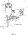
- the driving machine 201 includes: a striking mechanism (including a cylinder 245, the pressure accumulation container 250, the piston 47, and a blade 48) striking a nail 11 being a driving object; an electric motor 13 generating power for driving the striking mechanism; a power transmission mechanism moving the blade 48 of the striking mechanism by the power of the electric motor 13; a storage battery 15 supplying electricity to the electric motor 13; and a magazine 16 supplying the nail 11 to a shooting path of the striking mechanism one at a time and holding a plurality of the shot nails 11.
- the nail 11 is a stopper formed by sharpening a tip of a thin round bar or square bar and widening a rear end thereof into a flange shape, and the driving machine 201 is capable of striking nails of about 50 to 110 mm.
- the striking mechanism is accommodated within a main body housing 202 made of synthetic resin and having a cylindrical shape.
- a grip 203 for being held by an operator by one hand is provided on a lateral side of the main body housing 202, and a mounting portion 204 of the storage battery 15 is provided on an end portion of the grip 203.
- the storage battery 15 is attachable to and detachable from the mounting portion 204.
- a control circuit substrate 81 for mounting a later-described controller (control portion) is accommodated in the mounting portion 204.
- a seal member 55 is attached to an outer peripheral surface of the piston 47, and the piston 47 is reciprocally movable in the cylinder 245 in an axial direction along a center line B1.
- the blade 48 for driving the nail 11 and being axially elongated is fixed to a lower portion of the piston 47, and the pressure accumulation container 250 for storing air is provided on an upper portion of a space where the piston 47 moves.
- the pressure accumulation container 250 is formed by a container main body portion 251 having a substantial cup shape with an opening facing downward, and a flange portion 255 blocking the opening part of the container main body portion 251 and having formed therein an attaching portion for attachment to the cylindrical cylinder 245.
- An internal space (pneumatic chamber 249) of the pressure accumulation container 250 has the pneumatic chamber 249 that maintains the air introduced from the outside in a pressurized state, and is fluidly connected to a space (a later-described cylinder chamber 248 in FIG. 2 ) in which the air is compressed by the piston 47.
- the external air intake valve 260 is provided on an upper portion of the pressure accumulation container 250. Details of the external air intake valve 260 are described later.
- the storage battery 15 has an accommodation case and a plurality of battery cells (not illustrated) accommodated in the accommodation case.
- the battery cells are rechargeable and dischargeable DC secondary batteries, and may be lithium-ion batteries, nickel-hydrogen batteries, lithium-ion polymer batteries, nickel-cadmium batteries and so on.
- a part of the mounting portion 204 is connected to a motor housing 17 continuous with a casing 233.
- the main body housing 202, the grip 203, the mounting portion 204, the casing 233, and the motor housing 17 are made of a molded article made of synthetic resin such as plastic
- the nose portion 254 is made of aluminum alloy or iron-based metal, and these components constitute a case part (housing in a broad sense) of the driving machine 201.
- the electric motor 13 is a brushless DC motor, including a stator 18 unrotatably fixed to the motor housing 17, and a rotor 19 rotatably axially supported on an inner peripheral side of the stator 18.
- the stator 18 is formed by winding a coil 21 for energization around a stator core made of a laminated iron core.
- the rotor 19 includes an output shaft 24 supported by two bearings 82a and 82b, and a rotor core and a permanent magnet that are fixed to the output shaft 24.
- the output shaft 24 is rotatable about an axis line A1.
- a substantially annular inverter circuit substrate 83 is provided on an end portion side of the electric motor 13, and a plurality of switching elements 84 such as field-effect transistors (FETs) or insulated-gate bipolar transistors (IGBTs) that form a later-described inverter circuit are mounted thereon.
- switching elements 84 such as field-effect transistors (FETs) or insulated-gate bipolar transistors (IGBTs) that form a later-described inverter circuit are mounted thereon.
- FETs field-effect transistors
- IGBTs insulated-gate bipolar transistors
- a magnetic detection element such as a Hall integrated circuit (IC) for detecting a rotation position of the rotor 19 is provided on the inverter circuit substrate 83.
- a rotational force of the electric motor 13 is transmitted to a drive shaft 234 through a decelerator 27.
- a well-known speed reduction mechanism may be used as the decelerator 27.
- a rotational speed of the output shaft 24 is reduced to about one ten-oddth thereof, so as to rotate the drive shaft 234.
- a rotating body 238 is fixed to an end portion of the drive shaft 234 and rotates in synchronization with the drive shaft 234.
- the rotating body 238 constitutes a part of the power transmission mechanism that moves the blade 48 of the striking mechanism by the power of the electric motor 13, and configuration or operation thereof is described later in FIG. 2 to FIG. 4 .
- the nose portion 254 is attached to a shooting direction side of the main body housing 202, and forms the shooting path of the shot nail 11.
- a pushrod 104 is provided on the nose portion 254 so as to cover a tip part thereof.
- the pushrod 104 is movable with respect to the nose portion 254 in a predetermined range in the same direction as and in an opposite direction to the shooting direction, and is a kind of safety device used in performing a driving operation.
- the driving machine 201 is controlled so that, during driving of the nail 11, if the operator does not press the pushrod 104 against an object (driven material) into which the nail 11 is driven, the electric motor 13 does not rotate even if a trigger (trigger lever) 72 is pulled.
- the pushrod 104 When a tip side of the pushrod 104 in the shooting direction does not contact anything, the pushrod 104 is energized by a compression spring 105 and is located on the shooting direction side. When the operator presses the pushrod 104 against the object, the pushrod 104 moves in a direction opposite the shooting direction against a force of the compression spring 105 and then stops. When the pushrod 104 moves backward, a pressing detection switch (not illustrated) is switched on, and an output thereof is transmitted to a later-described controller. The controller allows activation of the electric motor 13 only when both states where the pushrod 104 is pressed and where the trigger 72 is pulled are realized.
- FIG. 2 is an arrow view as viewed from the direction A in FIG. 1 , showing a state where the piston 47 is at the bottom dead point.
- a moving mechanism is provided moving the piston 47 in a cylinder 45 in a direction in which pressure of the pneumatic chamber 249 is increased.
- This moving mechanism mainly includes the rotating body 238 rotated by a driving force of the electric motor 13, and the blade 48 having a rack 53.
- the rotating body 238 that has a pinion (gear) 241 on a part of its outer peripheral edge and meshing the pinion 241 with the rack 53 formed on a longitudinal side surface of the blade 48, the piston 47 is moved from the bottom dead point to the top dead point.
- the rotating body 238 and the pinion 241 are formed of an integral product made of metal, and the rotating body 238 is rotatable in a direction of arrow 242 or an opposite direction thereto by rotation of the drive shaft 234.
- the pinion 241 is arranged on the outer edge part of the rotating body 238 corresponding to a rotational angle of about 270 degrees.
- FIG. 3 shows a state where the rotating body 238 is rotated about 300 degrees in the direction of arrow 242 from the state in FIG. 2 , showing a state immediately before the meshing between the rack 53 and the whole pinion 241 ends and meshing between a lower end tooth 53b of the rack 53 and a rear end tooth 241b of the pinion 241 is just about to be released.
- a tip 48b of the blade 48 moves upward in a shooting path 256, the next nail 11 to be driven is fed from the magazine 16 into the shooting path 256.
- FIG. 3 shows a state where the rotating body 238 is rotated about 300 degrees in the direction of arrow 242 from the state in FIG. 2 , showing a state immediately before the meshing between the rack 53 and the whole pinion 241 ends and meshing between a lower end tooth 53b of the rack 53 and a rear end tooth 241b of the pinion 241 is just about to be released.
- FIG. 4 shows a state after FIG. 3 , and is an arrow view of the nose portion 254 after driving of the nail 11 is completed, as viewed from the side opposite the direction A in FIG. 1 .
- the drive shaft 234 also continues to rotate.
- a columnar pin 235 is provided parallel to the drive shaft 234, and the pin 235 acts on an off switch 236 at a timing at which the driving of the nail 11 ends.
- the off switch 236 is provided on a side surface of the nose portion 254, an output thereof is connected to a controller and an output pulse is transmitted at a timing at which the nail 11 is shot.
- An operating lever 237 for operating a plunger 236a is provided in the vicinity of the off switch 236.
- the operating lever 237 is made of a metal thin plate having elasticity, such as a spring material, and has on its tip a part bent into a semi-cylindrical shape.
- the controller stops supplying driving power to the electric motor 13.
- the drive shaft 234 also stops and the rotating body 238 stops in the position in FIG. 4 .
- the rack 53 and the pinion 241 are in a non-contact state.
- a magnetic sensor 257 Whether the nail 11 is correctly struck and whether the blade 48 has stopped in a correct position can be detected using a magnetic sensor 257.
- the magnetic sensor 257 is attached to the nose portion 254, and is provided in a position between the lower end tooth 53b of the rack 53 and an adjacent tooth when the piston 47 has moved to the bottom dead point. Due to approaching of the teeth of the rack 53 that protrude toward the magnetic sensor 257, the magnetic sensor 257 transmits a signal to the controller.
- the magnetic sensor 257 is large in FIG. 4 since it is schematically illustrated, in fact, the magnetic sensor 257 is miniaturized so as to be built in the nose portion 254, and a lead wire is also wired in an unnoticeable manner (thus, they are not illustrated in FIG. 1 to FIG. 3 ).
- the controller is capable of correctly identifying whether the blade 48 has moved to a shooting position according to presence or absence of this output signal. Since in this stopped state, the piston 47 is located at the bottom dead point, after the operator releases the pushrod 104 temporarily, by again pressing the pushrod 104 in a next striking position to pull the trigger 72, the next striking operation can be started. When nail clogging occurs, the lower end tooth 53b of the blade 48 does not pass in front of the magnetic sensor 257. Accordingly, when nail clogging is detected, pressure in a pressure accumulation chamber is released, and the operator performs an operation of removing the clogging nail after the release step.
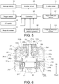
- FIG. 5 is a control block diagram of the driving machine 210 of the present example.
- An inverter circuit 65 is a circuit generating, from a DC current from the storage battery 15, a three-phase AC current (excitation current) for driving the electric motor 13, and is mounted on the inverter circuit substrate 83 (see FIG. 1 ) provided on a rear end side of the electric motor 13.
- the inverter circuit 65 includes six switching elements 84 (see FIG. 1 ) connected to the coil of the stator 18 of the electric motor 13, and on/off of the switching elements 84 is controlled by a controller 66.
- the controller 66 controls rotation of the electric motor 13 during striking (second step) of the nail 11 and controls rotation during pressurization (first step) of the pneumatic chamber 249 using the electric motor 13.
- the controller 66 is configured by including a microcomputer (hereinafter referred to as "micon") (not illustrated).
- a phase detection sensor 67 detecting a phase of the rotor 19 in a rotational direction is provided in the electric motor 13.
- the phase detection sensor 67 can be realized by including a plurality of Hall ICs that detect a magnetic field of the permanent magnet contained in the rotor 19 of the electric motor 13.
- the controller 66 is capable of obtaining a position of the rotor 19 in the rotational direction and a rotational speed of the rotor 19 based on a signal of the phase detection sensor 67.
- the controller 66 estimates a position of the rotating body 38 in the rotational direction, i.e., a rotational angle of the rotating body 38, based on the signal of the phase detection sensor 67 and a gear ratio of the decelerator 27.
- a rotational direction switching switch 68 is provided switching the rotational direction of the rotor 19 of the electric motor 13.
- the rotational direction switching switch 68 is operated by the operator.
- the rotational direction switching switch 68 has operation positions for normal rotation and reverse rotation.
- the signal of the off switch 236 that detects completion of the driving of the nail 11 and the signal of the magnetic sensor 257 that detects whether or not the blade 48 has reached the bottom dead point are inputted to the controller 66.
- the controller 66 processes the signal inputted from the phase detection sensor 67 so as to estimate the position of the piston 47 in the direction of the center line B1 of a cylinder 46.
- a trigger switch 71 (see FIG. 1 ) is a switch mechanism switched on and off by the operator operating the trigger 72 (see FIG. 1 ).
- a signal of the trigger switch 71 is inputted to the controller 66. Furthermore, a pressing detection sensor 121 is provided detecting whether or not the pushrod 104 is being pressed against the object, and a signal outputted from the pressing detection sensor 121 is inputted to the controller 66. Based on the signals of these switches and sensors, the controller 66 controls the rotation, stopping, rotational speed and rotational direction of the electric motor 13.
- the controller 66 controls the inverter circuit 65 to supply a current to the coil 21, and rotates the rotor 19 of the electric motor 13. Based on a signal of the rotational direction switching switch 68, the controller 66 controls a direction of the current flowing to the coil 21 and determines the rotational direction of the rotor 19. In addition, based on the signal of the phase detection sensor 67, the controller 66 detects the position of the rotor 19 in the rotational direction, and controls a timing of switching on and off the switching element of the inverter circuit 65 and an ON ratio, i.e., duty ratio, of the switching element.
- an ON ratio i.e., duty ratio
- the electric motor 13 is capable of switching the rotational direction of the rotor 19 between normal rotation and reverse rotation by switching the direction in which the current is supplied to the coil 21.
- a rotational force of the output shaft 24 is transmitted to the drive shaft 234 via the decelerator 27.
- the first step of increasing the air pressure in the pneumatic chamber 249 is performed in advance if necessary.
- the first step is a preparation step before start of the striking operation, and may be performed only when the pressure of the pneumatic chamber 249 is reduced (e.g., every several weeks to every several months). Normally, the process can be suddenly executed from the second step (normal driving operation).
- the second step when the operator presses the pushrod 104 against the object and pulls the trigger 72, the air pressure in the pneumatic chamber 249 further increases and the nail 11 is struck.
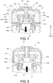
- FIG. 6 to FIG. 8 are partial enlarged views of the vicinity of the external air intake valve 260 provided in the pressure accumulation container 250 in FIG. 1 .
- FIG. 6 shows a state where the external air intake valve 260 is closed, showing a state where intake of the external air to the pressure accumulation container 250 is inhibited.
- the external air intake valve 260 is an on-off valve mechanism provided to pass through a through hole 251b provided on an upper side of the pressure accumulation container 250, wherein inflow of air from the external air toward the pneumatic chamber 249 is allowed in an opened state ( FIG. 7 and FIG.
- the pressure accumulation container 250 is accommodated within the main body housing 202 made of synthetic resin, and a cushion material 270 is provided on a lower side of the flange portion 255 so that the pressure accumulation container 250 is held without wobbling.
- the cylinder 245 and the cylindrical part of the flange portion 255 are screwed by a male thread 245c formed on a side of the cylinder 245 and a female thread 255c formed on an inner peripheral side of the flange portion 255.
- two O-rings 256a and 256b are interposed on an upper side of the screw part to improve confidentiality.
- the external air intake valve 260 is configured by including: a selector 265 being a main component of the valve mechanism; a cylindrical sleeve 262 for holding the selector 265 and moving the selector 265 in the axial direction (direction of the axis line B1), a movable mechanism (264, and 262a and 263b shown in FIG. 7 ) converting a rotational force of the cylindrical sleeve 262 into a moving force of the selector 265 in the axial direction; and a switching lever 261 for rotating the cylindrical sleeve 262.
- the switching lever 261 is a knob arranged inside a through hole 202b formed in an upper portion of the main body housing 202, and fixes the hollow cylindrical sleeve 262 having an external air intake passage 262a formed in the center.
- a through hole 261a is also formed in the center of an upper portion of the switching lever 261 and communicates with the external air intake passage 262a.
- a ring-shaped metal 266 is attached to a through hole formed in the container main body portion 251, and the cylindrical sleeve 262 is held movable in the B1 axial direction by the metal 266.
- a washer 267 is interposed between the switching lever 261 and the cylindrical sleeve 262.
- the selector 265 is provided on a lower side of the cylindrical sleeve 262.
- the selector 265 is configured to be movable in the axial direction while rotating, and has a cup-shaped inner wall surface abutting against an outer peripheral side of the cylindrical sleeve 262.
- a communicating path 265a for communicating the cup-shaped inner part with an outer part of the selector 265 is formed in the vicinity of a bottom (lower side surface) of the cup-shaped inner wall surface.
- the communicating path 265a is two or a plurality of through holes extending radially outward from an axial center of the selector 265, wherein when a lower end portion of the cylindrical sleeve 262 is separated from a bottom surface portion of the selector 265, the external air intake passage 262a and the pneumatic chamber 249 can communicate with each other by the communicating path 265a.
- a groove portion is formed so as to be continuous in a circumferential direction, and an O-ring 273 made of rubber is arranged in the groove portion.
- the O-ring 273 functions as a check valve to block flow of air from the side of the pneumatic chamber 249 toward the communicating path 265a, and, in contrast, to allow flow of the air from the side of the communicating path 265a toward the pneumatic chamber 249 when there is an air pressure difference.
- a cylindrical depression 265b having a cylindrical shape from bottom to top and two or a plurality of communicating paths 265c extending radially outward from the cylindrical depression 265b are further formed.
- a groove portion is formed so as to be continuous in the circumferential direction, and an O-ring 272 made of rubber and functioning as a check valve is arranged in the groove portion.
- the movable mechanism that converts the rotational force of the cylindrical sleeve 262 into the moving force of the selector 265 in the axial direction includes a collar 263 and a steel ball 264 provided on an inner peripheral side of the selector 265.
- a hemispherical depression 263a (see FIG. 7 ) is formed on an inner peripheral surface of the collar 263.
- a spline groove 262b formed over a rotational angle of 180 degrees while varying in the circumferential direction and axial direction is formed on an outer peripheral surface of the cylindrical sleeve 262.
- the steel ball 264 is arranged between the spline groove 262b and the depression 263a.
- the selector 265 is moved downward by the movable mechanism.
- a close contact between a stepped portion 265e formed on a lower side of the selector 265 and an opening portion 245a on an upper end of the cylinder 245 space of the pneumatic chamber 249 is separated from space of the cylinder chamber 248.
- an O-ring 271 arranged in an upper outer peripheral groove 265d (see FIG. 6 ) of the selector 265 abuts against an inner wall part of a cylindrical portion 252 formed on an inner peripheral side of the container main body portion 251, the pneumatic chamber 249 is maintained in a state sealed from the external air or the cylinder chamber 248.
- the O-ring 272 only flow of the air from the cylinder chamber 248 toward the pneumatic chamber 249 is allowed (only when there is a pressure difference).
- the operation of increasing the air pressure of the pneumatic chamber 249 in the first step is executed by moving the piston 47 in the cylinder chamber 248.
- a power source of the piston 47 may be anything as long as it is capable of moving the piston 47 or the blade 48.
- the blade 48 can be moved in an up-down direction by hand or by using a specialized movable tool.
- a driving source for moving the blade 48 during the striking operation is used.
- the pressurization in the pneumatic chamber 249 and the cylinder chamber 248 in the first step is performed using the electric motor 13.
- a brushless DC motor capable of detecting a rotation position with good accuracy by a micon and capable of performing control of normal rotation and reverse rotation with high accuracy is used. That is, in the first step, by reversely rotating the electric motor 13, the piston 47 that has reached a position immediately before the top dead point is lowered to the bottom dead point; when the piston 47 reaches the bottom dead point, by again normally rotating the electric motor 13, the piston 47 is moved to the position immediately before the top dead point.
- the reverse rotation and normal rotation of the electric motor 13 are performed within a range in which meshing between the rack 53 and the pinion 241 is not released, and are controlled with high accuracy by the micon contained in the controller 66.
- the air pressure of the pneumatic chamber 249 can be increased to about 3 to 5 atmospheres.
- the pneumatic chamber 249 is pressurized to a predetermined air pressure, since execution of the pressure accumulating mode is terminated by the micon, the operator returns the switching lever 261 of the external air intake valve 260 to the original position shown in FIG. 6 . In this state, advance preparation (pressure accumulating mode) for driving of the nail 11 is completed.
- the sequential procedure shown in FIG. 9 can be executed by software by the micon contained in the controller 66 using a pre-stored program.
- the flowchart in FIG. 9 is started from, as a state where the switching lever 261 is rotated from the state shown in FIG. 6 , and the selector 265 is lowered and the stepped portion 265e abuts against the opening portion 245a of the cylinder 245 as shown in FIG. 7 , a state where a switch (switching lever 261) of the pressure accumulating mode is switched on ("ON") (step 281).
- a sensor may be provided detecting the position of the switching lever 261, so that it can be detected by the controller 66 that the switching lever 261 is switched.
- the micon detects whether the pressure accumulating mode has become ON after the switching lever 261 is rotated (step 281). If the pressure accumulating mode is not achieved, standby is performed until the operator switches to the pressure accumulating mode (step 289).
- the micon detects whether or not the nail 11 remains in the magazine 16 and a nail shooting path (step 282). For this detection, a well-known stopper sensor or the like that detects whether the nail 11 is mounted in the shooting path 256 and presence or absence of the nail 11 may be provided. If the nail 11 remains in the magazine 16 or the shooting path, a warning lamp indicating that the nail 11 remains blinks, and standby is performed until the operator removes the nail 11 (step 290).
- step 283 when the nail 11 in the magazine 16 and the shooting path 256 is gone, rotation of the electric motor 13 becomes possible.
- the micon reversely rotates the electric motor 13 and reversely rotates a hoisting cam (rotating body 238), thereby moving the piston 47 to the bottom dead point side (step 283).
- the external air is attracted into the piston chamber 248 as shown by arrow 276 in FIG. 7 .
- step 283 terminates in an instant.
- the micon detects whether the nail 11 is clogging in the shooting path, i.e., whether a nail clogging state is present.
- the determination can be performed according to whether or not the detected current value I exceeds a threshold I 0 of current indicating nail clogging (step 284).
- the micon monitors the current value I at all times through a current detection circuit contained in a control circuit for driving the electric motor 13. Thus, by using a detected value thereof, there is no need to provide a new current detection means.
- the reason is that, when the piston 47 is lowered, if the piston 47 can be smoothly lowered by the electric motor 13, the current value I flowing to the motor does not become very large. If the current value I exceeds the set current value (threshold I 0 ), movement of the piston 47 and the blade 48 is thereby hindered. Therefore, the warning lamp indicating that the nail 11 remains blinks, and standby is performed until the operator removes the nail 11 (step 291).
- the micon normally rotates the electric motor 13 (rotation in a direction of hoisting the piston 47 during striking and rotation in a direction shown by the arrow in FIG. 2 ) to normally rotate the hoisting cam (rotating body 238), thereby moving the piston 47 from the bottom dead point to the vicinity of (before) the top dead point (step 285).
- the air (air attracted from the outside) in the cylinder chamber 248 can be sent into the pneumatic chamber 249 as shown by arrow 249 in FIG. 8 .
- the micon determines whether or not the pressure accumulation performed by the lowering and rising operations of the piston 47 is completed (step 286). Whether the pressure accumulation (pressurization operation) is completed can be carried out by, for example, any of the following methods. (1) The current value I flowing to the electric motor 13 when the piston 47 is moved from the bottom dead point side to the top dead point side is detected, so as to determine whether the current value I has become greater than a threshold I 1 at the time of completion of the pressure accumulation operation.
- a pressure sensor (not illustrated) measuring the pressure in the pneumatic chamber 249 is provided, and whether or not the pressure P exceeds a set pressure P 0 is detected. This method directly measures the air pressure and is therefore the most accurate method. However, since it is necessary to provide the pressure sensor, the cost will increase and devices will increase in size.
- the micon counts how many times the one-stroke operation has been executed, wherein the one-stroke operation refers to that the piston 47 is returned from the position immediately before the top dead point to the bottom dead point and is again raised from the bottom dead point to the position immediately before the top dead point.
- N is a threshold being a predetermined number of times
- the pressure accumulation operation is terminated.
- the threshold can be set to, for example, three times.
- step 292 If the pressure accumulating mode is maintained, standby is performed until the operator operates the switching lever 261 to switch off the pressure accumulating mode (step 292).
- the pressure accumulating mode becomes OFF i.e., when the switching lever 261 is returned to the state in FIG. 6
- the micon returns the piston 47 to an initial position (the bottom dead point or a predetermined position near the bottom dead point) (step 288), and the pressure accumulation process of the pneumatic chamber 249 by the first step is terminated. After that, the operator can execute the actual nail driving operation (second step).
- a manual leak mechanism i.e., the leak valve 360
- a pressure accumulation container 350 for allowing internal air to escape to the outside when pressure of a pneumatic chamber 349 exceeds a predetermined value
- the leak valve 360 is provided in a position adjacent to the external air intake valve 260 on an upper surface of the pressure accumulation container 350.
- the structure or function of the external air intake valve 260 is the same as that explained in the first example.
- the pressure accumulation container 350 is made in a two-piece form using a container main body portion 351 and a flange portion 355.
- a container storing compressed air it may be of an integral type or of a divided type, or may have other structures.
- the shape of an upper part of a main body housing 302 of the driving machine 301 changes with the change in the shape of the pressure accumulation container 350.
- the other parts have the same structures as those in the driving machine 201 of the first example.
- FIG. 11 is longitudinal sectional views showing a detailed structure of the leak valve 360.
- the leak valve 360 in addition to the function as a "release valve” which allows the internal air to escape to the outside when the pressure of the pneumatic chamber 349 (see FIG. 10 ) exceeds the predetermined value, a function as a "leak valve” which enables the operator to discharge the air in the pneumatic chamber 349 at arbitrary timing is provided.
- the nail 11 clogs in the shooting path 256 (see FIG. 2 ) formed in the nose portion 254
- the arbitrary exhaust function by the leak valve is convenient to use when removing the clogging nail 11. The reason is that, while the pressure of the pneumatic chamber 349 remains high, even if trying to remove the nail 11, it is sometimes difficult to move the blade 48.
- a through hole 353 being an outlet of the air in the pneumatic chamber 349 is formed in the container main body portion 351 of the pressure accumulation container 350, and the leak valve 360 is provided allowing discharge of the air from the through hole 353 in a predetermined state.
- the leak valve 360 is configured by including: a large-diameter portion 351c and a small-diameter portion 351d in which the container main body portion 351 protrudes inward in a cup shape; a cylindrical plunger 370 movable in the large-diameter portion 351c and the small-diameter portion 351d in the axial direction; a plunger holder 361 for holding the plunger 370 on the container main body portion 351; a push button 385 for moving the plunger 370; a ball 381 arranged inside the cylindrical plunger 370; and a pusher 382 for energizing the ball 381 in a predetermined direction.
- a plurality of passages (communicating paths 371 and 374), and a narrowed part 372 for realizing a valve mechanism by the ball 381 are formed in the plunger 370.
- O-rings 376 to 378 made of rubber and for maintaining airtightness between the plunger 370 and the plunger holder 361 are provided on an outer peripheral surface of the plunger 370.
- the ball 381 is inserted from outside the container main body portion 351 into the plunger 370, energized by the pusher 382 and a coil spring 383, and held by a metal plate 384.
- the metal plate 384 is retained by the push button 385 made of synthetic resin.
- a retaining ring 386 is inserted into a lower side of the push button 385.
- the plunger holder 361 holds the plunger 370 on the container main body portion 351, and forms or closes a predetermined air passage along with a groove portion on an outer peripheral side of the plunger 370.
- the plunger holder 361 passes through a through hole 302c of the main body housing 302, and is pressed into the large-diameter portion 351c of the container main body portion 351.
- An O-ring 363 is provided in order to maintain airtightness between the plunger holder 361 and the large-diameter portion 351c.
- a discharge pipeline 365 extending the container main body portion 351 in a direction orthogonal to the axial direction.
- the discharge pipeline 365 is formed by drilling or the like into a part of the container main body portion 351, and communicates outside the main body with a horizontal hole 361c formed in the plunger holder 361.
- FIG. 11(1) shows a state where the driving machine 301 is not in use or where a normal striking operation is being performed.
- (2) shows a state where the push button 385 is pressed down in a direction of arrow 395 by the operator, wherein by moving the push button 385 axially downward, an air passage from the through hole 353 to the discharge pipeline 365 is delimited as shown by arrow 391.
- the air passes through a gap between a lower end portion of the plunger holder 361 and an inside of the large-diameter portion 351c from the through hole 353, passes through a gap formed between an inclined surface portion on an inner peripheral side of the plunger holder 361 and an O-ring 377 to flow upward, and flows to the part of a wide groove 375 continuous in the circumferential direction so as to continue from the axial lower side.
- the air is discharged outside from the discharge pipeline 365, as shown by arrow 391. During discharge of the air, a discharge sound of high pressure air occurs.
- FIG. 11(3) shows a condition when the leak valve 360 acts as a release valve when pressurization of the pneumatic chamber 349 of the driving machine 301 is performed and a specified amount or more of air is taken in. It is assumed that the driving machine 301 of the present example drives a nail having a length of about 50 to 90 mm.
- the pressure in the pneumatic chamber is set to about 5 to 8 atmospheres; in the striking step (second step) of performing actual driving, the pressure in the pneumatic chamber is increased up to about 10 to 14 atmospheres. If the striking step is performed after the pressure accumulation in the first step is performed in a specified amount or more, the pressure of the pneumatic chamber 349 may exceed the predetermined value.
- the communicating path 371 is provided spatially connecting the narrowed part 372 closed by the ball 381 to the gap between the lower end portion of the plunger holder 361 and the inside of the large-diameter portion 351c, and the pressure (arrow 392) of the pneumatic chamber 349 is applied to the ball 381.
- the coil spring 383 is compressed through the pusher 382.
- the excess air flows around the ball 381 and is discharged outside through the communicating path 374, as shown by arrow 393.
- arrow 393 illustrates that the discharge is performed leftward
- the discharge may also be performed rightward in the same way.
- a spring force of the coil spring 383 becomes stronger than the pressure (arrow 392) of the pneumatic chamber 349, and the ball 381 is again pressed against the narrowed part 372.
- the leak valve 360 returns to the state in FIG. 11(1) , and the airtight state in the pneumatic chamber 349 is maintained.
- the removal of the nail can be performed in a safe state.
- the high pressure air in the pneumatic chamber 349 can be released if the operator wishes, a seal part of the pneumatic chamber or a seal portion of the piston can be prevented from aged deterioration at an early stage.
- a high pressure equal to or higher than a specified value is reached in the pneumatic chamber 349, since excess internal air can be automatically discharged, there is no fear of failure in the pressurization in the first step.
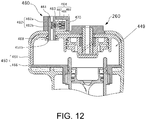
- FIG. 12 shows a modification of the second example, obtained by replacing the leak valve 360 in FIG. 11 with an electromagnetic valve 460.
- the electromagnetic valve 460 is arranged so as to pass through a container main body portion 451, wherein a discharge pipe 461 forming a communicating path 462 of discharged air, a valve 463 for opening or closing the communicating path 462, and a solenoid actuator 464 moving the valve 463 are provided.
- the discharge pipe 461 is a substantially cylindrical member in which an axial center is closed.
- the discharge pipe 461 is mounted in a through hole portion 451b of the container main body portion 451, and is attached by interposing an O-ring 468 made of rubber therebetween.
- extremely thin communicating paths 462a and 462b are formed extending in the axial direction and radial direction.
- the parts of the communicating paths 462a and 462b extending in the radial direction are exposed in a depressed part formed on an outer peripheral side of the discharge pipe 461, and the valve 463 is arranged so as to cover the depressed part.
- the solenoid actuator 464 moves an iron core 467 by magnetic force inside a coil 466 provided within a housing 465.
- the iron core 467 is fixed to the valve 463.
- the valve 463 By energizing the coil 466, the valve 463 is moved so as to approach the side of the communicating path 462; by stopping energization to the coil 466, the valve 463 is moved to the side away from the communicating path 462 due to action of a spring (not illustrated).
- a space is formed between the depressed part of the discharge pipe 461 and the valve 463, and the paths 462a and 462b communicate with each other. Therefore, air pressurized in a pneumatic chamber 449 can be discharged outside through the discharge pipe 461.
- the micon operating the electromagnetic valve 460 when an abnormality such as nail clogging occurs and the micon detects that it is necessary to remove the nail, by the micon operating the electromagnetic valve 460, high pressure air in the pneumatic chamber 449 can be released.
- the operator can perform removal of the nail can be performed in a safe state.
- the operator operates the external air intake valve 260 and the pressure accumulating mode to increase the pressure of the pneumatic chamber 449 can be executed.
- a user-friendly driving machine can be realized.
- FIG. 13 The basic configuration of FIG. 13 is almost the same as that of the driving machine 201 explained in the first example, particularly in terms of the nail feeding mechanism such as the magazine 16, driving performed by the electric motor 13, shape of a grip 101 or a mounting portion 1, that the storage battery 15 is used as a power source, and that the storage battery 15 is attachable to and detachable from a mounting portion 102.
- a main difference lies in a striking mechanism 12 that strikes the nail 11, and the mechanism for pressurizing a pneumatic chamber is different.
- a pneumatic chamber is constituted by the movable second cylinder 46, and the cylinder 46 is movable in the up-down direction by the driving force of the electric motor 13 (described later).
- a shape of a cover 100 also varies according to the form of the cylinder 46.
- the electric motor 13 (not illustrated) is provided within the motor housing 17, and its structure is a brushless DC motor of the same type as that explained in FIG. 1 .
- the decelerator 27 of the same type as that explained in FIG. 1 is accommodated in the casing 33 adjacent to the motor housing 17, and the casing 33 is connected to a cylindrical nose portion 54.
- FIG. 14 is a side view as viewed from the direction A in FIG. 13 , and a part thereof is shown in sectional view.
- a rotational driving force of the electric motor 13 is transmitted to a drive shaft 34 and a driven shaft 35 through an output of the decelerator 27.
- two power transmission paths i.e., a first power transmission path driven by rotation of the driven shaft 35 and a second power transmission path driven by rotation of the drive shaft 34, are provided.
- the first power transmission path is movable in the up-down direction of the movable second cylinder 46 using a gear 44 rotated by the driven shaft 35.
- the second power transmission path moves the blade 48 upward using a gear 41 rotated by the drive shaft 34, thereby moving the piston 47 (see FIG.
- the drive shaft 34 is arranged concentrically with the output shaft 24 (see FIG. 1 ) of the electric motor 13 and is rotatable about the axis line A1.
- a rotating body 37 and the rotating body 38 are attached to the drive shaft 34.
- a gear 40 is provided on an outer peripheral surface of the rotating body 37, and a rotational force is transmitted toward the driven shaft 35 by the gear 40.
- the gear 40 is provided on the outer peripheral surface of the rotating body 37.
- a one-way clutch 39 (see FIG. 15 ) is provided connecting or blocking the power transmission path between the rotating body 37 and the drive shaft 34.
- the one-way clutch 39 does not transmit the rotational force of the drive shaft 34 to the rotating body 37. That is, the one-way clutch 39 connects or blocks the power transmission path between the drive shaft 34 and the driven shaft 35 according to the rotational direction of the drive shaft 34.
- the gear 41 is provided within a predetermined angle range on the outer peripheral surface of the rotating body 38.
- a roller 42 is provided at a part where the gear 41 is not provided.
- a part of an outer peripheral surface of the roller 42 is arranged outside the outer peripheral surface of the rotating body 38.
- the roller 42 is rotatably supported.
- the gear 44 is provided on the driven shaft 35.
- the gear 44 meshes with the gear 40.
- the blade 48 is arranged along the center line B1 and is movable within a shaft hole 52 (see FIG. 15 ).
- a rotation stopper 73 being a holding member that restricts rotation of a rotating body 60 is provided on the casing 33.
- the rotation stopper 73 is swingable about a support shaft 74.
- the rotation stopper 73 prevents the rotating body 60 from rotating in the counterclockwise direction in FIG. 14 and allows the rotating body 60 to rotate in the clockwise direction. That is, the gear 61 and the rotation stopper 73 constitute a ratchet mechanism.
- the rack 53 is provided on the blade 48 in the length direction.
- the gear 41 is capable of meshing with or being detached from the rack 53.
- the casing 33 has the cylindrical nose portion 54, and the blade 48 is movable in the nose portion 54.
- the nose portion 54 is exposed outside the cover 100 (see FIG. 13 ).
- the pushrod 104 is provided on the nose portion 54.
- the pushrod 104 is movable with respect to the nose portion 54 in a predetermined range in the direction along the center line B1.
- the pushrod 104 is pressed and stopped in the direction along the center line B1 by the force of the compression spring 105 (see FIG. 15 ).
- the pushrod 104 moves in the direction of the center line B1 against the force of the compression spring 105 (see FIG. 15 ) and then stops.
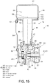
- FIG. 15 is a front sectional view of the driving machine shown in FIG. 13 .
- the striking mechanism 12 includes the first cylinder 45, the second cylinder 46, the piston 47 and the blade 48.
- the cylinders 45 and 46 are arranged within the cover 100 (see FIG. 13 ).
- the cylinder 45 includes a cylindrical portion 49, and an outward-facing flange 50 continuous with the cylindrical portion 49.
- the center line B1 of the cylindrical portion 49 intersects with the axis line A1 at a substantially right angle, and a first end portion (lower end portion) of the cylindrical portion 49 in the direction along the center line B1 is fixed to the casing 33.
- a part of a power transmission mechanism 14 is provided in the casing 33.
- the power transmission mechanism 14 includes the drive shaft 34 and the driven shaft 35 arranged parallel to each other.
- the drive shaft 34 is rotatably supported by the casing 33 through a bearing 36.
- the drive shaft 34 is arranged concentrically with the output shaft 24 and is rotatable about an axis line D1.
- the rotating bodies 37 and 38 are attached to the drive shaft 34.
- the rotating body 37 is arranged between the rotating body 38 and the decelerator 27 in a direction along the axis line A1.
- the rotational direction of the drive shaft 34 is the same as the rotational direction of the rotor 19 of the electric motor 13.
- a one-way clutch 43 is provided between the rotating body 38 and the drive shaft 34.
- the one-way clutch 43 transmits the rotational force of the drive shaft 34 to the rotating body 38; when the drive shaft 34 rotates in the counterclockwise direction, the one-way clutch 43 does not transmit the rotational force of the drive shaft 34 to the rotating body 38.
- the gear 40 is provided on the outer peripheral surface of the rotating body 37.
- the one-way clutch 39 is provided connecting or blocking the power transmission path between the rotating body 37 and the drive shaft 34.
- the one-way clutch 39 transmits the rotational force of the drive shaft 34 to the rotating body 37.
- the one-way clutch 39 does not transmit the rotational force of the drive shaft 34 to the rotating body 37. That is, the one-way clutch 39 connects or blocks the power transmission path between the drive shaft 34 and the driven shaft 35 according to the rotational direction of the drive shaft 34.
- the flange 50 is provided on a second end portion (upper end portion) of the cylindrical portion 49 in the direction along the center line B1 being an axis line of the cylinder 45.
- an annular damper 51 integrally formed of a rubber-like elastic body is provided between the cylindrical portion 49 and the casing 33.
- the damper 51 includes the shaft hole 52.
- the piston 47 is reciprocally movable in the cylindrical portion 49 in the direction along the center line B1, and the seal member 55 is attached to the outer peripheral surface of the piston 47.
- the shaft-shaped blade 48 is connected to or fixed to the piston 47.
- the cylinder 46 includes a cylindrical portion 56 and a circular plate portion 57 continuous with the cylindrical portion 56.
- the flange 50 is arranged in the cylindrical portion 56, and the cylinder 46 is movable with respect to the cylinder 45 in the direction along the center line B1.
- a seal member 103 is attached to an outer peripheral surface of the flange 50, and a pneumatic chamber 58 is formed in the cylinder 46.
- the pneumatic chamber 58 communicates with the inside of the cylinder 45.
- a breathing hole 59 is provided penetrating the cylindrical portion 56 in the radial direction.
- the breathing hole 59 connects the inside and outside of the pneumatic chamber 58.
- the seal members 55 and 103 airtightly seal the pneumatic chamber 58.
- the air being a compressible fluid goes into and out of the pneumatic chamber 58 through the breathing hole 59.
- the rotating body 60 having the gear 61 provided on its outer peripheral surface is attached to a part of the driven shaft 35 that is exposed outside the casing 33.
- the rotating body 60 is rotatable about the axis line D1 along with the driven shaft 35.
- a support shaft 62 is provided in a position eccentric from the axis line D1.
- a support shaft 63 is provided on the cylinder 46.
- a conrod 64 is provided connecting the rotating body 60 and the cylinder 46. The conrod 64 is rotatably attached to the support shafts 62 and 63, and constitutes, along with the rotating body 60, an opening and closing mechanism that opens a ventilation passage.
- the electric motor 13 is stopped.
- the cylinder 46 is stopped in the initial position in FIG. 14 and FIG. 15 .
- the pneumatic chamber 58 is connected to outside of the pneumatic chamber 58 through the breathing hole 59. That is, the initial pressure in the pneumatic chamber 58 and the cylinder 45 is the same as atmospheric pressure.
- the piston 47 contacts the damper 51 and then stops, and the gear 41 does not mesh with the rack 53 (see FIG. 14 ).
- the operator operates the rotational direction switching switch 68 (see FIG. 5 ), so as to set the rotational direction of the drive shaft 34 to the counterclockwise direction in FIG. 14 , and to apply an operating force to the trigger 72.
- the pushrod 104 may not be pressed against the object, but may not move unless being pressed.
- the trigger switch 71 when the trigger switch 71 is switched on, the electric motor 13 rotates.
- the drive shaft 34 is rotated in the counterclockwise direction in FIG. 14 by the rotational force of the electric motor 13.
- the rotational force of the drive shaft 34 is transmitted to the driven shaft 35 through the one-way clutch 39, and the driven shaft 35 and the rotating body 60 integrally rotate in the clockwise direction in FIG. 14 .
- the controller 66 stops the electric motor 13. That is, the cylinder 46 stops in the vicinity of (the bottom dead point) where the circular plate portion 57 is about to contact the flange 50 of the cylinder 45.
- the circular plate portion 57 of the cylinder 46 receives the pressure of the pneumatic chamber 58, and the cylinder 46 is energized in a rising direction along the center line B1.
- the energizing force received by the cylinder 46 is transmitted to the rotating body 60 through the conrod 64. That is, the rotating body 60 receives a rotational force in the counterclockwise direction in FIG. 14 .
- the operator operates the rotational direction switching switch 68 in order to perform the striking step (second step), so as to set the rotational direction of the electric motor 13 opposite that set in the first step.
- the electric motor 13 is stopped at a time point when the rotational direction is set.
- the electric motor 13 rotates when the trigger 72 is operated, and the drive shaft 34 rotates in the clockwise direction in FIG. 14 .
- the one-way clutch 39 does not transmit the rotational force of the drive shaft 34 to the driven shaft 35.
- the piston 47 is rapidly lowered toward the damper 51 by the air pressure in the pneumatic chamber 58 and the cylinder 45, and the blade 48 strikes the nail 11 to drive the nail 11 into the object. Then, the piston 47 collides with the damper 51 and then stops.
- the electric motor 13 rotates even after the gear 41 has been separated from the rack 53. When the gear 41 reaches a predetermined position, i.e., before the gear 41 meshes with the rack 53, the electric motor 13 stops. After that, by the operator separating the pushrod 104 from the object, the driving operation of the nail 11 terminates.
- the pressure in the pneumatic chamber 58 and the cylinder 45 can be reduced.
- the nail 11 can be easily removed.
- the air pressure of the pneumatic chamber 58 can be released, there is no need to provide a seal member for maintaining high pressure of the air chamber.
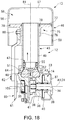
- FIG. 17 to FIG. 18 A driving machine corresponding to the fourth example is shown in FIG. 17 to FIG. 18 .
- the driving machine 10 in FIG. 17 includes the same structure and the same elements as those of the driving machine 10 shown in the third example.
- the cylinder 45 has a cylindrical shape.
- the flange 50 explained in Example 3 is not provided, and instead a partition 75 attached to the cylinder 45 is provided.
- the partition 75 includes a cylindrical portion 76 movable along an outer peripheral surface of the cylindrical portion 49 of the cylinder 45, and an outward-facing flange 77 continued from the cylindrical portion 76.
- An outer diameter of the flange 77 is less than an inner diameter of the cylindrical portion 56.
- the partition 75 is movable with respect to the cylinder 45 and the cylinder 46 in the direction along the center line B1.
- a seal member 78 is attached to an inner peripheral surface of the cylindrical portion 76, and the seal member 78 airtightly seals between the outer peripheral surface of the cylindrical portion 49 and the partition 75.
- a seal member 79 is attached to an outer peripheral surface of the flange 77. The seal member 79 airtightly seals between an inner peripheral surface of the cylindrical portion 56 and the flange 77.
- a support shaft 80 is provided on an outer peripheral surface of the cylindrical portion 76, and the conrod 64 is rotatably connected to the support shaft 80. That is, the rotating body 60 and the partition 75 are connected to each other in a manner capable of transmitting power through the conrod 64.
- the arrangement range of the support shaft 80 and the conrod 64 in the radial direction of the center line B1 is less than the inner diameter of the cylindrical portion 56.
- the first step of increasing the air pressure of the pneumatic chamber 58 is performed.
- the air pressure of the pneumatic chamber 58 is further increased and the nail 11 is struck.
- the operator operates the rotational direction switching switch 68 to switch the rotational direction of the electric motor 13, and sets the rotational direction of the drive shaft 34 in the first step to the counterclockwise direction in FIG. 17 .
- the partition 75 is stopped in an initial position in FIG. 17 before the drive shaft 34 starts rotating.
- the pneumatic chamber 58 is connected to outside of the pneumatic chamber 58 through the breathing hole 59. That is, the pressure in the pneumatic chamber 58 and the cylinder 45 is the same as atmospheric pressure.
- the piston 47 contacts the damper 51 and is then stopped.
- the electric motor 13 is stopped. That is, the partition 75 stops before reaching the top dead point.
- the flange 77 of the partition 75 receives the pressure of the pneumatic chamber 58, and the partition 75 is energized in the direction approaching the casing 33 along the center line B1.
- the energizing force received by the partition 75 is transmitted to the rotating body 60 through the conrod 64. That is, the rotating body 60 receives a rotational force in the counterclockwise direction in FIG. 17 .
- the operator operates the rotational direction switching switch 68 in order to perform the second step, and switches the rotational direction of the electric motor 13.
- the operation in the second step hereafter is the same as that in the third example.
- the whole length of the driving machine 10 in the direction along the center line B1 does not change.
- the whole length of the driving machine 10 is a height from the tip of the pushrod 104 to the upper end of the cylinder 45.
- FIG. 19 and FIG. 20 A driving machine corresponding to the fifth example of the present invention is shown in FIG. 19 and FIG. 20 .
- the driving machine 10 shown in FIG. 19 can use the electric motor 13, the decelerator 27, the rotating body 38, the piston 47, the roller 42, the blade 48 and the cylinder 45 having the same structures as those in the driving machine 10 of the fourth example.
- the driving machine 10 in FIG. 19 does not include the first power transmission path part (the driven shaft 35, the rotating body 37, the one-way clutch 43 and the conrod 64) of the fourth example.
- the driving machine 10 instead includes an outer cylinder 106 fixed to the casing 33, and the cylinder 45 is arranged in the outer cylinder 106.
- An inner cylinder 107 is provided in the outer cylinder 106.
- the cylinder 45 is arranged between the inner cylinder 107 and the casing 33 in the direction along the center line B1.
- the inner cylinder 107 includes a large-diameter portion 108 and a small-diameter portion 109.
- the small-diameter portion 109 is arranged between the large-diameter portion 108 and the casing 33 in the direction along the center line B1.
- An inner diameter of the large-diameter portion 108 is larger than an inner diameter of the small-diameter portion 109.
- the inner cylinder 107 has a connecting portion 117 connecting the large-diameter portion 108 and the small-diameter portion 109.
- the connecting portion 117 has an annular shape.
- a breathing hole 111 is provided penetrating the large-diameter portion 108 in the radial direction.
- An end portion of the cylinder 45 in the length direction is fixed to the small-diameter portion 109.
- a seal member 110 is provided sealing between an outer peripheral surface of the cylinder 45 and an inner peripheral surface of the small-diameter portion 109.
- a holder 112 is fixed to the outer cylinder 106.
- a screw member 113 is provided fixing the holder 112 to the outer cylinder 106.
- the inner cylinder 107 is positioned and fixed to the outer cylinder 106 in the direction along the center line B1.
- the breathing hole 111 is connected to outside of the outer cylinder 106 through inside of the outer cylinder 106.
- a plunger 114 is attached to the holder 112.
- the plunger 114 is a mechanism using a screw member, and a male thread of a shaft portion 115 of the plunger 114 is formed.
- a female screw hole 116 is provided in the holder 112, and the shaft portion 115 is inserted into the female screw hole 116.
- the operator can manually rotate the plunger 114 in normal and reverse directions, and the plunger 114 is movable in the direction along the center line B1 when rotated in either direction. When the rotational direction of the plunger 114 differs, the direction in which the plunger 114 moves along the center line B1 differs.
- a movable partition 118 is attached to a tip of the shaft portion 115.
- the movable partition 118 is arranged in the large-diameter portion 108.
- the movable partition 118 is a circular plate rotatable about the center line B1 with respect to the shaft portion 115.
- An outer diameter of the movable partition 118 is less than the inner diameter of the large-diameter portion 108, and an annular seal member 119 is attached to an outer peripheral surface of the movable partition 118.
- a pneumatic chamber 120 is formed from a space between the movable partition 118 and the connecting portion 117 and across in the cylinder 45.
- the seal members 55, 110 and 119 airtightly seal the pneumatic chamber 120.
- the breathing hole 111 connects the inside and outside of the pneumatic chamber 120.
- the configuration and operation of the second power transmission path part including the rotating body 38 are the same as those in the third to fourth examples.
- the rotational direction switching switch 68 for switching the rotational direction of the electric motor 13 is not provided since it is unneeded.
- the operator When using the driving machine 10, before pressing the pushrod 104 against the object, the operator performs the first step of increasing air pressure of the pneumatic chamber 120. In the second step, the operator further increases the air pressure of the pneumatic chamber 120, and presses the pushrod 104 against the object to strike the nail 11.
- the drive shaft 34 is stopped before the operator performs the first step.
- the piston 47 contacts the damper 51.
- the movable partition 118 is stopped in a position shown in chain double-dashed lines in FIG. 14 . That is, the pneumatic chamber 120 is connected to outside of the outer cylinder 106 through the breathing hole 111, and pressure of the pneumatic chamber 120 is the same as atmospheric pressure.
- the operator rotates the plunger 114 in a predetermined direction using a spanner or the like, so as to move the plunger 114 in the direction along the center line B1.
- the plunger 114 lowers in a direction approaching the cylinder 45.
- the movable partition 118 blocks the pneumatic chamber 120 and the breathing hole 111, and the pressure of the pneumatic chamber 120 increases with movement of the movable partition 118.
- the operator stops the movable partition 118 in a predetermined position in the direction along the center line B1. Hence, the pressure of the pneumatic chamber 120 is maintained at the first pressure higher than atmospheric pressure.
- the operation in the second step is the same as that in the third and the fourth examples.
- the driving machine 10 in the fifth example by rotating the plunger 114 in a direction opposite that mentioned above and moving the plunger 114 in the direction of the center line B1 in a direction away from the cylinder 45, the pressure of the pneumatic chamber 120 can be reduced.
- the movable partition 118 rises in the direction away from the cylinder 45 along with the plunger 114, the seal member 119 reaches between the breathing hole 111 and the holder 112 in the direction of the center line B1, and the breathing hole 111 is connected to the pneumatic chamber 120.
- the air pressure of the pneumatic chamber 120 is reduced to become the same as atmospheric pressure. Accordingly, the driving machine 10 of the fifth example obtains the same effects as those obtained by the driving machine 10 of Example 4.
- the driving machine of the present invention is not limited to the above embodiments but can be modified in various ways without departing from the gist thereof.
- the motor that transmits power to the drive shaft may be, in addition to an electric motor, an engine, a hydraulic motor, or a pneumatic motor.
- the electric motor may be either a brushed motor or a brushless motor.
- a power supply for the electric motor may be either a DC power supply or an AC power supply.
- compressed air having an initial pressure higher than atmospheric pressure and equal to or lower than the first pressure may be filled into the pneumatic chamber 58 and the cylinder 45.
- the center line B1 is shown as an up-down direction, i.e., vertical direction.
- the driving machine 10 can be used with the center line B1 being inclined with respect to the vertical direction.
- the object to be driven by the driving machine includes, in addition to a shaft-shaped nail, a lateral U-shaped nail.
- the shaft-shaped nail includes a nail having a head or a nail having no head.
- the first pressure and the second pressure in the present invention are not fixed values but vary depending on conditions such as an operation amount of a movable member, pressure receiving area and so on.
- the rotational direction of the rotor 19 of the electric motor 13 is switched to switch the rotational direction of the drive shaft 34.
- a rotational direction switching mechanism in the power transmission path between the electric motor 13 and the drive shaft 34 and controlling the rotational direction switching mechanism, it is possible to switch the rotational direction of the drive shaft 34 without switching the rotational direction of the electric motor 13.
Landscapes
- Engineering & Computer Science (AREA)
- Mechanical Engineering (AREA)
- Physics & Mathematics (AREA)
- Fluid Mechanics (AREA)
- Portable Nailing Machines And Staplers (AREA)
Applications Claiming Priority (3)
| Application Number | Priority Date | Filing Date | Title |
|---|---|---|---|
| JP2015037416 | 2015-02-26 | ||
| JP2015189060 | 2015-09-26 | ||
| PCT/JP2016/054905 WO2016136632A1 (ja) | 2015-02-26 | 2016-02-19 | 打込機 |
Publications (2)
| Publication Number | Publication Date |
|---|---|
| EP3263286A1 true EP3263286A1 (de) | 2018-01-03 |
| EP3263286A4 EP3263286A4 (de) | 2018-11-07 |
Family
ID=56788747
Family Applications (1)
| Application Number | Title | Priority Date | Filing Date |
|---|---|---|---|
| EP16755378.3A Withdrawn EP3263286A4 (de) | 2015-02-26 | 2016-02-19 | Antriebsmaschine |
Country Status (5)
| Country | Link |
|---|---|
| US (1) | US20180036870A1 (de) |
| EP (1) | EP3263286A4 (de) |
| JP (1) | JP6481751B2 (de) |
| CN (1) | CN107249823A (de) |
| WO (1) | WO2016136632A1 (de) |
Cited By (3)
| Publication number | Priority date | Publication date | Assignee | Title |
|---|---|---|---|---|
| EP3308907A4 (de) * | 2015-06-10 | 2019-01-23 | Koki Holdings Co., Ltd. | Antriebsmaschine |
| EP3790707A4 (de) * | 2018-05-08 | 2022-10-05 | Techtronic Cordless GP | Verfahren zum erkennen eines werkstückverklemmungszustands in einem befestigungswerkzeug |
| US12564925B2 (en) | 2018-06-11 | 2026-03-03 | Milwaukee Electric Tool Corporation | Gas spring-powered fastener driver |
Families Citing this family (53)
| Publication number | Priority date | Publication date | Assignee | Title |
|---|---|---|---|---|
| WO2016127101A1 (en) * | 2015-02-06 | 2016-08-11 | Milwaukee Electric Tool Corporation | Gas spring-powered fastener driver |
| NZ735578A (en) | 2015-03-30 | 2019-03-29 | Senco Brands Inc | Lift mechanism for framing nailer |
| CN105818099B (zh) * | 2016-05-26 | 2017-11-17 | 杭州科龙电器工具股份有限公司 | 使用气弹簧的电动钉枪 |
| TWI781941B (zh) * | 2016-07-29 | 2022-11-01 | 日商工機控股股份有限公司 | 釘打機 |
| JP6730900B2 (ja) * | 2016-09-29 | 2020-07-29 | 大和ハウス工業株式会社 | シート貼合装置 |
| EP3326757B1 (de) | 2016-11-09 | 2022-03-16 | Techtronic Cordless GP | Zylinderanordnung für einen gasfederbefestigungstreiber |
| FI3558595T3 (fi) | 2016-12-22 | 2023-12-14 | Kyocera Senco Industrial Tools Inc | Kiinnittimen käyttötyökalu, jossa on käyttölaitteen paikka-anturit |
| US10800022B2 (en) * | 2017-02-09 | 2020-10-13 | Illinois Tool Works Inc. | Powered-fastener-driving tool including a driver blade having a varying cross-section |
| JP6881576B2 (ja) * | 2017-05-31 | 2021-06-02 | 工機ホールディングス株式会社 | 打込機 |
| CN110997242B (zh) * | 2017-07-31 | 2024-03-08 | 工机控股株式会社 | 打入机 |
| TWI744560B (zh) * | 2017-11-02 | 2021-11-01 | 鑽全實業股份有限公司 | 氣壓式釘槍及其撞針裝置 |
| TWI804476B (zh) * | 2017-11-02 | 2023-06-11 | 鑽全實業股份有限公司 | 氣壓式電動釘槍 |
| WO2019208102A1 (ja) * | 2018-04-24 | 2019-10-31 | 工機ホールディングス株式会社 | 打込機 |
| EP3578306A1 (de) * | 2018-06-06 | 2019-12-11 | HILTI Aktiengesellschaft | Setzgerät |
| US12427634B2 (en) | 2018-06-11 | 2025-09-30 | Milwaukee Electric Tool Corporation | Gas spring-powered fastener driver |
| US11724375B2 (en) * | 2018-07-06 | 2023-08-15 | Koki Holdings Co., Ltd. | Driving tool with switching mechanism |
| DE102018117519A1 (de) * | 2018-07-19 | 2020-01-23 | Prebena Wilfried Bornemann Gmbh & Co. Kg | Druckluftbetriebene Austreibvorrichtung |
| CA3106685C (en) * | 2018-08-28 | 2023-12-05 | Kyocera Senco Industrial Tools, Inc. | Forced air cooling from piston movements of nailer tool |
| USD900575S1 (en) | 2018-09-26 | 2020-11-03 | Milwaukee Electric Tool Corporation | Powered fastener driver |
| US11130221B2 (en) | 2019-01-31 | 2021-09-28 | Milwaukee Electric Tool Corporation | Powered fastener driver |
| JP7263831B2 (ja) * | 2019-02-22 | 2023-04-25 | マックス株式会社 | 空気圧式工具 |
| EP3698925B1 (de) * | 2019-02-22 | 2021-10-06 | Max Co., Ltd. | Pneumatisches werkzeug |
| CN110253503B (zh) * | 2019-06-11 | 2022-03-22 | 南京腾亚精工科技股份有限公司 | 一种紧固件击打工具 |
| US11951601B2 (en) | 2019-06-14 | 2024-04-09 | Milwaukee Electric Tool Corporation | Lifter mechanism for a powered fastener driver |
| US12479074B2 (en) | 2019-06-14 | 2025-11-25 | Milwaukee Electric Tool Corporation | Lifter mechanism for a powered fastener driver |
| US12179326B2 (en) | 2019-06-14 | 2024-12-31 | Milwaukee Electric Tool Corporation | Lifter mechanism for a powered fastener driver |
| CN217394880U (zh) * | 2019-06-14 | 2022-09-09 | 米沃奇电动工具公司 | 动力紧固件驱动器 |
| ES2904999T3 (es) * | 2019-07-02 | 2022-04-06 | Bea Gmbh | Clavadora neumática con un dispositivo de seguridad |
| CN110385675B (zh) * | 2019-07-10 | 2022-03-08 | 南京腾亚精工科技股份有限公司 | 一种紧固件打击工具 |
| US11618144B2 (en) * | 2019-08-26 | 2023-04-04 | Taizhou Dajiang Ind. Co., Ltd | Energy storage mechanism and nail gun having same |
| CN110802557B (zh) * | 2019-10-22 | 2022-11-08 | 南京信息职业技术学院 | 一种机械式泡钉打钉器 |
| US12076844B2 (en) | 2020-02-05 | 2024-09-03 | Kyocera Senco Industrial Tools, Inc. | Gas spring fastener driving tool with fill valve located in an end cap |
| TWI822953B (zh) * | 2020-02-06 | 2023-11-21 | 鑽全實業股份有限公司 | 氣瓶式電動釘槍 |
| WO2021192838A1 (ja) * | 2020-03-24 | 2021-09-30 | 株式会社マキタ | 打ち込み工具 |
| WO2021195188A1 (en) | 2020-03-25 | 2021-09-30 | Milwaukee Electric Tool Corporation | Powered fastener driver |
| AU2021267838B2 (en) | 2020-05-07 | 2024-03-21 | Kyocera Senco Industrial Tools, Inc. | Power driving tool with latch position sensor |
| JP7459648B2 (ja) * | 2020-05-14 | 2024-04-02 | マックス株式会社 | 打ち込み工具 |
| WO2022011631A1 (en) * | 2020-07-16 | 2022-01-20 | Techtronic Cordless Gp | Fastening tool with a crank transmission |
| US20220063074A1 (en) * | 2020-08-26 | 2022-03-03 | Robert Bosch Gmbh | Gas Spring for a Fastener Driving Tool |
| CN114310795B (zh) * | 2020-09-30 | 2025-06-17 | 株式会社牧田 | 打入工具 |
| US12162125B2 (en) | 2020-10-30 | 2024-12-10 | Milwaukee Electric Tool Corporation | Powered fastener driver |
| JP7646379B2 (ja) * | 2021-02-03 | 2025-03-17 | 株式会社マキタ | 打ち込み工具 |
| JP2024517010A (ja) | 2021-05-07 | 2024-04-18 | キョウセラ センコ インダストリアル ツールズ インク. | メンテナンス又は点検を実行するために取り外し可能なエンドキャップを有するガススプリング締結具駆動ツール |
| US12521854B2 (en) | 2021-07-16 | 2026-01-13 | Milwaukee Electric Tool Corporation | Gas spring-powered fastener driver with pressure mechanism |
| CN218984691U (zh) * | 2021-11-04 | 2023-05-09 | 苏州宝时得电动工具有限公司 | 钉枪 |
| TWI865846B (zh) * | 2021-12-16 | 2024-12-11 | 鑽全實業股份有限公司 | 可調整動能的電動釘槍 |
| WO2024004878A1 (ja) * | 2022-06-29 | 2024-01-04 | 工機ホールディングス株式会社 | 作業機 |
| CN115024851B (zh) * | 2022-08-01 | 2023-10-20 | 暨南大学 | 自动化脊髓损伤动物模型制备装置 |
| US12420395B2 (en) * | 2022-08-15 | 2025-09-23 | Taizhou Dajiang Ind. Co. Ltd. | Nail passage and driving mechanisms and nail gun having same |
| WO2024036918A1 (zh) * | 2022-08-15 | 2024-02-22 | 台州市大江实业有限公司 | 过钉机构及射钉枪 |
| CN118721117A (zh) * | 2023-03-30 | 2024-10-01 | 台州市大江实业有限公司 | 一种射钉枪用蓄力机构及射钉枪 |
| US12569969B2 (en) * | 2023-06-08 | 2026-03-10 | Tricord Solutions, Inc. | Impacting apparatus |
| US20260124726A1 (en) * | 2024-11-07 | 2026-05-07 | Koki Holdings Co., Ltd. | Working machine |
Family Cites Families (32)
| Publication number | Priority date | Publication date | Assignee | Title |
|---|---|---|---|---|
| US3278106A (en) * | 1965-04-15 | 1966-10-11 | Senco Products | Firing control means |
| US3278104A (en) * | 1965-09-14 | 1966-10-11 | Senco Products | Fastener applying device |
| US4215808A (en) * | 1978-12-22 | 1980-08-05 | Sollberger Roger W | Portable electric fastener driving apparatus |
| US4679719A (en) * | 1985-12-27 | 1987-07-14 | Senco Products, Inc. | Electronic control for a pneumatic fastener driving tool |
| DE3728454C2 (de) * | 1987-08-26 | 1993-12-23 | Bosch Gmbh Robert | Druckmittelbetriebenes Schlaggerät |
| WO1996012591A1 (en) * | 1994-10-21 | 1996-05-02 | Senco Products, Inc. | Pneumatic fastener driving tool and an electronic control system therefor |
| JP3676879B2 (ja) * | 1995-07-25 | 2005-07-27 | 株式会社マキタ | 締結具打込み工具 |
| US5927585A (en) * | 1997-12-17 | 1999-07-27 | Senco Products, Inc. | Electric multiple impact fastener driving tool |
| WO2004011201A1 (fr) * | 2002-07-25 | 2004-02-05 | Yih Kai Enterprise Co.,Ltd. | Outil de clouage a main |
| JP2005288608A (ja) * | 2004-03-31 | 2005-10-20 | Jpf Works Kk | 携帯式ファスナー打ち込み工具 |
| US20060180631A1 (en) * | 2005-02-16 | 2006-08-17 | Chris Pedicini | Electric motor driven energy storage device for impacting |
| JP4687572B2 (ja) * | 2006-06-14 | 2011-05-25 | 日立工機株式会社 | 打込機 |
| CN201012490Y (zh) * | 2007-02-08 | 2008-01-30 | 旭吉股份有限公司 | 电动击钉机构 |
| JP5090018B2 (ja) * | 2007-03-06 | 2012-12-05 | 株式会社マキタ | ねじ打ち込み機 |
| US8011547B2 (en) * | 2007-10-05 | 2011-09-06 | Senco Brands, Inc. | Fastener driving tool using a gas spring |
| US7793811B1 (en) * | 2009-02-25 | 2010-09-14 | Tricord Solutions, Inc. | Fastener driving apparatus |
| US8042717B2 (en) * | 2009-04-13 | 2011-10-25 | Stanley Fastening Systems, Lp | Fastener driving device with contact trip having an electrical actuator |
| JPWO2011010511A1 (ja) * | 2009-07-24 | 2012-12-27 | トリコード ソリューションズ,インコーポレイティド | 打込み工具 |
| JP2012187640A (ja) * | 2009-07-24 | 2012-10-04 | Makita Corp | 打込み工具 |
| JP5585417B2 (ja) * | 2010-11-26 | 2014-09-10 | 日立工機株式会社 | 打込機 |
| DE102011076087A1 (de) * | 2011-05-19 | 2012-11-22 | Hilti Aktiengesellschaft | Eintreibgerät |
| WO2013027396A1 (en) * | 2011-08-23 | 2013-02-28 | Hitachi Koki Co., Ltd. | Fastening tool |
| JP5748104B2 (ja) * | 2011-09-30 | 2015-07-15 | 日立工機株式会社 | 打込機 |
| DE102012210347A1 (de) * | 2012-06-19 | 2013-12-19 | Hilti Aktiengesellschaft | Setzgerät und Steuerungsverfahren |
| JP2014008566A (ja) * | 2012-06-29 | 2014-01-20 | Hitachi Koki Co Ltd | 打込機 |
| JP2014028422A (ja) * | 2012-07-31 | 2014-02-13 | Hitachi Koki Co Ltd | 打込機 |
| JP5849920B2 (ja) * | 2012-09-28 | 2016-02-03 | 日立工機株式会社 | 打込機 |
| JP2014104533A (ja) * | 2012-11-27 | 2014-06-09 | Makita Corp | 打ち込み工具 |
| WO2015037299A1 (ja) * | 2013-09-10 | 2015-03-19 | 株式会社マキタ | 打ち込み工具 |
| CA3146951A1 (en) * | 2014-03-27 | 2015-10-01 | Techtronic Power Tools Technology Limited | Powered fastener driver and operating method thereof |
| TWI781941B (zh) * | 2016-07-29 | 2022-11-01 | 日商工機控股股份有限公司 | 釘打機 |
| US10710227B2 (en) * | 2016-11-09 | 2020-07-14 | Tti (Macao Commercial Offshore) Limited | Control system for gas spring fastener driver |
-
2016
- 2016-02-19 JP JP2017502330A patent/JP6481751B2/ja active Active
- 2016-02-19 EP EP16755378.3A patent/EP3263286A4/de not_active Withdrawn
- 2016-02-19 CN CN201680011204.2A patent/CN107249823A/zh active Pending
- 2016-02-19 WO PCT/JP2016/054905 patent/WO2016136632A1/ja not_active Ceased
- 2016-02-19 US US15/551,041 patent/US20180036870A1/en not_active Abandoned
Cited By (9)
| Publication number | Priority date | Publication date | Assignee | Title |
|---|---|---|---|---|
| EP3308907A4 (de) * | 2015-06-10 | 2019-01-23 | Koki Holdings Co., Ltd. | Antriebsmaschine |
| US10843317B2 (en) | 2015-06-10 | 2020-11-24 | Koki Holdings Co., Ltd. | Driver |
| US11590638B2 (en) | 2015-06-10 | 2023-02-28 | Koki Holdings Co., Ltd. | Driver |
| US12434363B2 (en) | 2015-06-10 | 2025-10-07 | Koki Holdings Co., Ltd. | Driver |
| EP3790707A4 (de) * | 2018-05-08 | 2022-10-05 | Techtronic Cordless GP | Verfahren zum erkennen eines werkstückverklemmungszustands in einem befestigungswerkzeug |
| US11667018B2 (en) | 2018-05-08 | 2023-06-06 | Techtronic Power Tools Technology Limited | Nailers with jamming-alleviating mechanisms |
| US12202109B2 (en) | 2018-05-08 | 2025-01-21 | Techtronic Cordless Gp | Method of detecting a workpiece jam condition in a fastener tool |
| US12350798B2 (en) | 2018-05-08 | 2025-07-08 | Techtronic Power Tools Technology Limited | Nailers with jamming-alleviating mechanisms |
| US12564925B2 (en) | 2018-06-11 | 2026-03-03 | Milwaukee Electric Tool Corporation | Gas spring-powered fastener driver |
Also Published As
| Publication number | Publication date |
|---|---|
| US20180036870A1 (en) | 2018-02-08 |
| EP3263286A4 (de) | 2018-11-07 |
| WO2016136632A1 (ja) | 2016-09-01 |
| JP6481751B2 (ja) | 2019-03-13 |
| CN107249823A (zh) | 2017-10-13 |
| JPWO2016136632A1 (ja) | 2017-11-30 |
Similar Documents
| Publication | Publication Date | Title |
|---|---|---|
| US20180036870A1 (en) | Driving machine | |
| US11571792B2 (en) | Driver | |
| US12544895B2 (en) | Driver, pressure regulator and driving unit | |
| EP3479964B1 (de) | Antriebsvorrichtung | |
| EP3321037B1 (de) | Steuerungssystem für gasfederbefestigungstreiber | |
| CN107708934B (zh) | 打入机 | |
| US8800834B2 (en) | Fastener driving apparatus | |
| CA2841205C (en) | Pneumatic fastener driver | |
| JP7115544B2 (ja) | 打込機 | |
| FI127302B (fi) | Polttokenno ja polttokäyttöinen työkalu | |
| US20170361444A1 (en) | Gas spring fastener driver | |
| EP3036069B1 (de) | Treiber für eine pneumatische befestigung | |
| TW201803702A (zh) | 釘打機 | |
| US5181450A (en) | Pneumatic fastener driving apparatus with piston holding detent | |
| JPWO2018180082A1 (ja) | 打込機 | |
| JP2010115775A (ja) | 空気打込機 | |
| JP7004066B2 (ja) | 打込機 | |
| JPWO2011010511A1 (ja) | 打込み工具 | |
| TWI523739B (zh) | Pneumatic electric nail gun | |
| JPWO2020179305A1 (ja) | 打込機 | |
| WO2014084222A1 (ja) | 打ち込み工具 | |
| US20210237241A1 (en) | Driving tool | |
| TWI729351B (zh) | 釘打機 | |
| JP5783379B2 (ja) | 打込機 | |
| JP6950547B2 (ja) | 打撃作業機 |
Legal Events
| Date | Code | Title | Description |
|---|---|---|---|
| STAA | Information on the status of an ep patent application or granted ep patent |
Free format text: STATUS: THE INTERNATIONAL PUBLICATION HAS BEEN MADE |
|
| PUAI | Public reference made under article 153(3) epc to a published international application that has entered the european phase |
Free format text: ORIGINAL CODE: 0009012 |
|
| STAA | Information on the status of an ep patent application or granted ep patent |
Free format text: STATUS: REQUEST FOR EXAMINATION WAS MADE |
|
| 17P | Request for examination filed |
Effective date: 20170814 |
|
| AK | Designated contracting states |
Kind code of ref document: A1 Designated state(s): AL AT BE BG CH CY CZ DE DK EE ES FI FR GB GR HR HU IE IS IT LI LT LU LV MC MK MT NL NO PL PT RO RS SE SI SK SM TR |
|
| AX | Request for extension of the european patent |
Extension state: BA ME |
|
| DAV | Request for validation of the european patent (deleted) | ||
| DAX | Request for extension of the european patent (deleted) | ||
| RAP1 | Party data changed (applicant data changed or rights of an application transferred) |
Owner name: KOKI HOLDINGS KABUSHIKI KAISHA |
|
| RAP1 | Party data changed (applicant data changed or rights of an application transferred) |
Owner name: KOKI HOLDINGS CO., LTD. |
|
| A4 | Supplementary search report drawn up and despatched |
Effective date: 20181010 |
|
| RIC1 | Information provided on ipc code assigned before grant |
Ipc: B25C 1/06 20060101AFI20181004BHEP |
|
| RAP1 | Party data changed (applicant data changed or rights of an application transferred) |
Owner name: KOKI HOLDINGS CO., LTD. |
|
| STAA | Information on the status of an ep patent application or granted ep patent |
Free format text: STATUS: THE APPLICATION HAS BEEN WITHDRAWN |
|
| 18W | Application withdrawn |
Effective date: 20200218 |