EP3264346A2 - Verarbeitung von sendungen in lade- und vertriebsnetzen auf basis von gewicht- und volumeninformationen - Google Patents
Verarbeitung von sendungen in lade- und vertriebsnetzen auf basis von gewicht- und volumeninformationen Download PDFInfo
- Publication number
- EP3264346A2 EP3264346A2 EP17178786.4A EP17178786A EP3264346A2 EP 3264346 A2 EP3264346 A2 EP 3264346A2 EP 17178786 A EP17178786 A EP 17178786A EP 3264346 A2 EP3264346 A2 EP 3264346A2
- Authority
- EP
- European Patent Office
- Prior art keywords
- consignment
- measured
- information
- cage
- volume
- Prior art date
- Legal status (The legal status is an assumption and is not a legal conclusion. Google has not performed a legal analysis and makes no representation as to the accuracy of the status listed.)
- Granted
Links
Images






Classifications
-
- G—PHYSICS
- G06—COMPUTING OR CALCULATING; COUNTING
- G06Q—INFORMATION AND COMMUNICATION TECHNOLOGY [ICT] SPECIALLY ADAPTED FOR ADMINISTRATIVE, COMMERCIAL, FINANCIAL, MANAGERIAL OR SUPERVISORY PURPOSES; SYSTEMS OR METHODS SPECIALLY ADAPTED FOR ADMINISTRATIVE, COMMERCIAL, FINANCIAL, MANAGERIAL OR SUPERVISORY PURPOSES, NOT OTHERWISE PROVIDED FOR
- G06Q10/00—Administration; Management
- G06Q10/08—Logistics, e.g. warehousing, loading or distribution; Inventory or stock management
-
- G—PHYSICS
- G01—MEASURING; TESTING
- G01G—WEIGHING
- G01G19/00—Weighing apparatus or methods adapted for special purposes not provided for in the preceding groups
- G01G19/002—Weighing apparatus or methods adapted for special purposes not provided for in the preceding groups for postal parcels and letters
- G01G19/005—Weighing apparatus or methods adapted for special purposes not provided for in the preceding groups for postal parcels and letters with electric or electronic computing means
-
- G—PHYSICS
- G06—COMPUTING OR CALCULATING; COUNTING
- G06Q—INFORMATION AND COMMUNICATION TECHNOLOGY [ICT] SPECIALLY ADAPTED FOR ADMINISTRATIVE, COMMERCIAL, FINANCIAL, MANAGERIAL OR SUPERVISORY PURPOSES; SYSTEMS OR METHODS SPECIALLY ADAPTED FOR ADMINISTRATIVE, COMMERCIAL, FINANCIAL, MANAGERIAL OR SUPERVISORY PURPOSES, NOT OTHERWISE PROVIDED FOR
- G06Q10/00—Administration; Management
- G06Q10/08—Logistics, e.g. warehousing, loading or distribution; Inventory or stock management
- G06Q10/083—Shipping
Definitions
- the invention relates to processing consignments in a pick-up and delivery (PUD) network on the basis of weight and volume information, and, in particular, though not exclusively, to methods and systems for processing consignments in a pick-up and delivery network on the basis of weight and volume information that is generated at different consignment processing locations, e.g. hubs, in the PUD network and computer program product for executing such methods.
- PUD pick-up and delivery
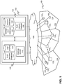
- Fig. 1 depicts PUD system comprising a PUD network 108 connected via a network 106 to a network management system 100 including a front-end system 102 and a back-end system 104 .
- the PUD network 108 comprises several network stations 132 1-4 , e.g. depots and hubs, through which the mail pieces are routed to arrive at a destination address DA.
- Each PUD network is associated with a service area. Physical transport of the mail pieces between network stations is conducted using trucks, aircrafts and other delivery vehicles.
- PUD networks may span wide areas, e.g. continents, and may contain tens of hubs and hundreds to thousands of depots.
- an agreed delivery time applies for the delivery of the consignment.
- Service providers typically offer several service levels, such as economy delivery and express delivery, for which different delivery times (and delivery costs) apply to convey a consignment from an origin address through the PUD network to the destination address.
- Service providers may convey millions of consignments through the PUD network each week. Obviously, the routing of the consignments through the network must be managed within such delivery networks in order to efficiently route the consignments through the PUD network while meeting agreed delivery times.
- the front-end system 102 may process delivery orders from customers contacting the system via a booking system 110 which may be accessed via a user interface, e.g. a web-interface,
- a customer may use a customer terminal 128 1-4 , e.g. a computer, in order to fill in a delivery order form listing several possible PUD services.
- the booking system may connect to a PUD services database 114 in order to retrieve service information (maximum weight, maximum dimensions, delivery times, etc.) for each of the PUD services.
- the booking system may further use a user profile database 124 in order to retrieve information about the customer requesting a delivery order.
- the shipment information includes the required service level, the origin address, the destination address and may contain physical characteristics, most notably the weight and volume of the mail piece(s) of the consignment.
- the mail pieces are provided with a marking (e.g. an identifier, typically a bar code), which is registered with the network by scanning a code that is attached to the piece.
- Information on the consignment may be linked to the marking and stored in a consignment database.
- the physical characteristics (weight and dimensions) of the consignment are initially used for determining a price that is billed to a customer.
- the delivery process is further handled by the back-end 104 comprising a PUD network manager 126 that is connected to the computers in the hub and depots and to mobile terminals of drivers who are transporting the consignments from the origin address to an origin depot or from a destiny depot to a destiny address.
- the PUD network manager is further connected to a consignment database comprising the shipment information and to a location database comprising the locations of the hubs and depots of the PUD network.
- the marking is scanned, typically using a hand scanner, such that the PUD network manager recognizes the ID and is informed about the current location of the mail piece in the delivery network.
- the current location of the mail piece may be stored in the location database.
- consignments are registered with the PUD network when they enter the PUD network on the basis of shipment information provided by the customers. Thereafter the consignment is transported through the PUD network to the destination address.
- the PUD network manager will receive a depot location where the consignment has been detected but for the rest is the transport of the consignment through the network a black box process for the network management system thereby seriously limiting the possibilities to control, optimize and improve the delivery services.
- a consignment e.g. a non-stackable pallet, may influence the efficiency of loading a truck with a certain amount of consignments.
- aspects of the present invention may be embodied as a system, method or computer program product. Accordingly, aspects of the present invention may take the form of an entirely hardware embodiment, an entirely software embodiment (including firmware, resident software, micro-code, etc.) or an embodiment combining software and hardware aspects that may all generally be referred to herein as a "circuit,” “module” or “system.” Functions described in this disclosure may be implemented as an algorithm executed by a microprocessor of a computer. Furthermore, aspects of the present invention may take the form of a computer program product embodied in one or more computer readable medium(s) having computer readable program code embodied, e.g., stored, thereon.
- These computer program instructions may also be stored in a computer readable medium that can direct a computer, other programmable data processing apparatus, or other devices to function in a particular manner, such that the instructions stored in the computer readable medium produce an article of manufacture including instructions which implement the function/act specified in the flowchart and/or block diagram block or blocks.
- the computer program instructions may also be loaded onto a computer, other programmable data processing apparatus, or other devices to cause a series of operational steps to be performed on the computer, other programmable apparatus or other devices to produce a computer implemented process such that the instructions which execute on the computer or other programmable apparatus provide processes for implementing the functions/acts specified in the flowchart and/or block diagram block or blocks.
- each block in the flowchart or block diagrams may represent a module, segment, or portion of code, which comprises one or more executable instructions for implementing the specified logical function(s).
- the functions noted in the blocks may occur out of the order noted in the figures. For example, two blocks shown in succession may, in fact, be executed substantially concurrently, or the blocks may sometimes be executed in the reverse order, depending upon the functionality involved.
- One aspect of the invention discloses a system for monitoring the physical structure of consignments transported in a pick-up-and-delivery (PUD) network, the monitoring being based on measured consignment information, such as measured weight and measured volume of a consignment, the system comprising:
- the computer system may further be adapted to: compare the first measured consignment information with the second measured consignment information; and, if the first measured consignment information does not deviate from the second measured consignment information, setting a confirmation flag in the database, the confirmation flag signaling that the physical structure of the consignment identified by the consignment identifier has not been changed during transportation from the first consignment processing location to the second consignment processing location.
- the first and second scanning system may comprise a weighting system comprising one or more scales, the one or more scales being integrated in the flour of the consignment processing location such that the surface of the floor matches the top surface of the scales.
- the first and second scanning system controller may be adapted to use the consignment identifier and the measured consignment information for determining a first and second loading locating for the consignment at the premises of the first and second consignment processing location respectively; and, to display routing information for guiding a driver to said determined loading location.
- the first and second scanning system may comprise one or more conveyor belts, wherein at least one of said one or more conveyor belts comprises a scale for determining the weight of consignments that are transported within the consignment processing location via said one or more conveyor belts.
- thein invention relates to scanning system for routing consignments in a consignment processing location on the basis of measured consignment information, such as measured weight and measured volume of a consignment, the system comprising:
- the invention relates to a scanning system for routing consignments in a consignment processing location on the basis of measured consignment information, such as measured weight and measured volume of a consignment, the system comprising:
- the cage or truck may be provided with a scan readable code coding a cage or truck identity and wherein logging on the cage or truck involves scanning the code and communicating the cage or truck identity to the programmable control unit and linking the cage or truck identity to a chute identity of the chute to which the cage or truck is linked.
- the code may be a bar code, a QR code or a RFID tag.
- the number, weight and/or joint volume of all consignments assigned to a given chute during the time that a given cage or truck is logged-on is determined and compared with the number or weight of the collected consignments in the cage or truck after the cage or truck has been logged out or with the maximum total loading volume of the cage or turck to determine the identity of the parcels left on the chute after the cage or truck was logged-off.
- a marker may be used to indicate whether or not a cage or truck is logged-in.
- Still other aspects of the invention relate to a computer program and a, preferably non-transitory, computer readable storage medium storing the computer program.
- the computer program contains instructions (software code portions) which, when executed by a processor of a data processing system, carry out steps of one or more of the methods described above.
- the invention aims to monitor and control processes in the depots and hubs and the processes in a PUD network on the basis of measured physical characteristics of the consignments that enter and leave the depots and hubs.
- the physical characteristics are measured on the basis of special high-throughput weight and volume scanning systems (hereafter referred to as scanning system) that are installed at the entrance of hubs and depots of the PUD network.
- Each scanning system is adapted for both weighting and determining the volume and/or dimensions of a consignment.
- the scanning system may also configured to determine images of different sides of a consignment.
- Each scanning system measures the weight and volume of a consignment, identifies the consignment by determining a code, e.g. a bar code or QR code representing an consignment identifier, in at least one of the images of the consignment and sent this information to the network management system of the PUD network
- Fig. 2 depicts part of a PUD system according to an embodiment of the invention.
- Fig. 2 depicts a PUD system that is similar to the PUD system as described with reference to Fig. 1 .
- the PUD system comprises a monitoring system 225 coupled to the PUD network manager 226 .
- the monitoring system is coupled via the network 206 to at least one scanning system 233 1-4 that are located in the hubs and/or depots 232 1-4 of the PUD network 208.
- Each depot or hub comprises at least one at least one scanning system for registering and monitoring the measured characteristics such as the weight, volume and shape of consignments at the input (and optionally the output).
- This information is referred to as the measured consignment information.
- the measured consignment information such as the weight, volume and dimensions, of each consignment (identified by a consignment ID, e.g. a bar code or a QR code) generated by a scanning system at a particular geographical location is transmitted via a communications network 206 to a network management system of the PUD system where it is processed by the monitoring system.
- the measured consignment information may be stored in a measured consignment information database 203 and linked on the basis of the consignment ID to other information regarding the consignment, e.g.
- the consignment and location database receive measured consignment information such as the weight and volume of the consignment for different locations (hub and depot locations) in the PUD network. This way, the physical constitution of the consignment can be monitored during the PUD process.
- a consignment information processor 204 is configured to monitor the measured consignment information in time and if deviations and/or changes in the measured consignment information is determined, the consignment information processor may trigger an appropriate action. Different applications are described hereunder in further detail.
- Fig. 3 depicts part of a consignment processing location comprising one or more scanning systems according to an embodiment of the invention.
- Fig. 3 depicts a depot 332 comprising a scanning system 333 coupled to a controller 340 , which in turn is connected via a network 306 to the monitoring system (not shown) as described in detail with reference to Fig. 2 .
- the scanning system may comprising one or more 335 1-3 scanning units so that it is possible to process consignments in parallel.
- the depot may comprising a plurality of unload positions 342 .
- a vehicle 344 may park at an unload position so that consignments can be unloaded and be transported to the scanning system.
- consignments of the vehicle at the unload position may be scanned by scanning unit 335 1 which determines for each consignment measured consignment information including the weight and volume of the consignment and an consignment ID (e.g. by analysing images of the sides of the consignment for a marker, a code representing the consignment ID and, optionally, information on the destination location).
- the measured consignment information may be stored by the controller in a local database 348 and sent by the controller via the network 306 to the monitoring system.
- the measure consignment information 350 may have the format of a consignment profile 352 associated with a certain time instance (e.g. a time stamp) and location (e.g. hub location).
- the measured consignment information may be used by the controller 340 to generate depot routing information 332 .
- the depot routing information is used to route a scanned consignment through the depot, in particular to at least one of the load positions 342 of the hub at which an vehicle 346 1-3 is parked which is designated by the PUD system to transport the consignment to a further depot or to the destination address.
- the controller receives information from the network management system and/or from the controller which vehicles are currently positioned at load position and which vehicle(s) is (are) capable of delivering the scanned consignment at a certain location.
- the controller may determine a route through the hub to a designated vehicle at a certain load position. Hence, if more vehicles are available the controller may use the measured weight and/or volume in order to select a vehicle that is most suitable for the particular consignment. To that end, the controller has access to specific capabilities (type, loading capacity, loading dimensions, etc.) of the vehicles. Hence, this way, the measured consignment information is able help the system to help selecting which vehicle is most suitable or capable of delivering a consignment. This is particular useful in case of large consignments or consignments with a specific shape or consignments that are not stackable.
- the determination of the route may include generating visual information, e.g. a map and/or an indicator, so that a forklift driver is able to transport the consignment, e.g. an non-conveyable consignment such as a pallet of the like, to the desired load position.
- the determination of the route may include controlling one or more conveyor belts for routing conveyable consignment via conveyor belts to the desired load position.
- Fig. 4 depicts part of a PUD system according to an embodiment of the invention.
- Fig. 4 depicts a PUD system comprising a monitoring system 425 comprising a database 400 for storing measured consignment information and a consignment information processor 404 , wherein the monitoring system is further coupled to the PUD network manager 426 .
- the monitoring system is connected via a network 406 to scanner system controllers 433 1-4 that are located at hubs 432 1-4 in the PUD network in a similar way as described with reference to Fig . 2 and 3 .
- scanner system controllers 433 1-4 that are located at hubs 432 1-4 in the PUD network in a similar way as described with reference to Fig . 2 and 3 .
- the scanner system of the first hub will determine the measured consignment information and the controller may send this information as a check-in consignment profile 433 1 to the monitoring system, which stores the profile in the measured consignment information database.
- the check-in consignment profile describes the physical state of the consignments when it enters the PUD network. Thereafter, the consignment may be routed in the depot to a further vehicle at a load position which will transport the consignment to a further depot 432 2 that may execute a similar scanning process producing a transit consignment profile 433 2 .
- transit consignment profiles 433 2,3 are generated and delivered to the monitoring system, wherein the transit consignment profiles describe the physical state of the consignment at the depots when the consignment is in transit.
- the scanning system of the last depot 432 4 will generate a check-out consignment profile 433 4 describing the physical state of the consignment at the end of the delivery route.
- the thus generated consignment profiles provides traceable evidence of the physical state of the consignment when it is transported through the PUD network.
- the measured consignment information may be used by the PUD network to provide an accurate overview of the physical status of consignments in the PUD network. Moreover, it provide more accurate information for network capacity planning, contingency planning (both at the level of a depot or hub and at the level of the PUD network) and ultimately rating and invoicing.
- non-conveyable consignments e.g. goods that are packaged on a pallet
- the scanning system may be optimized for use with non-conveyable consignments that are transported in the depot by forklifts.
- conveyable consignments are transported within a depot on the basis of one or more conveyor belts.
- a conveyer belt may comprise a scanning section for automatic weighting and volume scanning of the consignments transported on the belt.
- Fig. 5 depicts a schematic of a scanning system for non-conveyable consignments according to an embodiment of the invention.
- Fig. 5 depicts a scanning system 502 for non-conveyable consignments that is optimized for high throughput processing by forklifts.
- the scanning system comprising a weighting system 516 comprising a plurality of independently controllable electronic scale units 520 1-9 and a volume scanning system 522 1,2 comprising a number of movable lasers and/or cameras 526 1 , 2 ; 528 1 , 2 .
- the scanning system may comprise a mounting frame 524 1,2 for mounting movable camera's so that the cameras can be moved to different x,y positions in a plane parallel to the top surface of the scales.
- Volume measurement is performed using a volume scanner comprising lasers and mirrors enabling providing dimensioning data for both cuboid and non-cuboid objects.
- Software is used, e.g. in computer system, to calculate a three-dimensional volume shape of the consignment as the smallest enclosing rectangular box in real time and may also be used to determine stackability of a consignment.
- the camera's may be part of a camera-based identification system that is configured to image the sides (four sides, one top) of the consignment and to detect on the basis of the image data one or more markings, e.g. a code representing the consignment ID and, optionally, information about the destination location.
- a camera-based identification system configured to image the sides (four sides, one top) of the consignment and to detect on the basis of the image data one or more markings, e.g. a code representing the consignment ID and, optionally, information about the destination location.
- the scanning system is connected to a scanning system controller 504 for controlling the scanning process and a display 508 (e.g. one or more large displays mounted close to the scanning system, a display in the forklift truck, a mobile phone or another graphical user interface such as a head-mounted display, e.g. Google glasses).
- a display 508 e.g. one or more large displays mounted close to the scanning system, a display in the forklift truck, a mobile phone or another graphical user interface such as a head-mounted display, e.g. Google glasses.
- the controller will display information on the scanning process to a user. This information may include: routing information 510 , scanning information 512 and a process indicator 514 that signals the status of the one or more process steps of the scanning.
- the electronic scales may be integrated in the flour of a depot such that the surface of the floor matches the top surface of the scales. This way forklifts can mount and demount consignments in a very fast way.
- the plurality of scales (the matrix of scales) under the volume scanning system can be controlled such that one or more of the scales of the plurality of scales form a scale for a consignments of a particular size.
- the plurality of scales can be effectively configured into scales of different sizes. This way scanning processes of different consignments can be partly processed in parallel.
- the display informs a forklift driver about the status of the scanning process using a process indicator 514 . Further it can display scanned information 512 , e.g. weight and volume, and warehouse routing information 510 .
- scanned information 512 e.g. weight and volume, and warehouse routing information 510 .
- the data may be stored in a database 500 and/or forwarded to the VCM 525 which can use this information for capacity planning purposes.
- the volume and weight information is also used for optimizing and to increasing the safety of processes within a depot or a hub.
- the scanning system of Fig. 5 can be used for high throughput scanning of non-conveyable consignments. This process, which is executed by the scanning system controller 504 connected to the management system of the PUD network, is illustrated hereunder with reference to Fig. 6A-6D.
- Fig. 6A depicts a first phase wherein the controller of a scanning system (as described with reference to Fig. 5 ) displays via the status display 608 that consignments can be loaded onto the scales.
- a scale indicator 624 in the display signals a forklift driver which scale units are ready for receiving a consignment.
- the scanning system further comprises a truck fleet indicator 622 displaying trucks that are arranged at the unload section of the depot (the incoming truck fleet indicator) and trucks that are arranged at the load section of the depot (the outgoing truck fleet indicator) which ready for receiving scanned consignments.
- the ingoing and outgoing truck fleet indicator may indicate at which positions of the unload and load positions trucks are present, e.g.
- Incoming consignments 606 1-3 are ready to be scanned, wherein each consignment comprises at least one marker 608 1-3 , e.g. a code representing the consignment ID and, optionally, the destination location, for identification purposes.
- a second phase as shown in Fig. 6B different consignments may be loaded onto different scales of the plurality of scale units of the weighting system of the scanning system.
- the weighting system senses that a first consignment 606 1 is loaded onto four electronic scale units. Therefore, the scanning system controller configures these scale units as a first combined scale for weighting the first consignment.
- a second consignment 606 2 is loaded on two electronic scale units that are configured by the controller as a second combined scale for weighting the second consignment and a third consignment 606 3 is loaded on a single electronic scale for weighting the third consignment.
- the first combined scale may weigh the first consignment and transmits the measured weight to the scanning system controller which may display the value onto the dashboard.
- the measured weight may be further stored in a data base 600 .
- the scale units that are active in the weighting process may be displayed on the display. Further, the display may signal that the scanning system is in the "scanning status".
- the scanning system controller uses this information in order to define a scanning area 608 which the volume scanning system uses in order to determine a volume of the first consignment via a well-known laser scanning process. Further, the system captures images of the consignment that include a marker representing the ID of the consignment (e.g. a bare code). These images may be analysed and the marker may be recognized using well-known image recognition software. The thus determined consignment ID can be displayed on the display as well.
- a marker representing the ID of the consignment e.g. a bare code
- the scanning system controller determines that the volume scanning process was successful and displays the measure volume onto the display.
- the measured consignment information in this case the consignment ID, the measured weight and the measured volume is stored in a database and forwarded to the PUD network manager.
- the PUD network manager may use the scanned information in combination with the geographical location of the depot in the PUD network and other relevant information (e.g. destination address, delivery type, etc.) to select a particular loading truck that is ready for shipment of the consignment.
- the scanning system controller may display routing information for informing the driver of the forklift the route within the warehouse to the loading truck. The forklift driver then unloads the first consignment and transports the consignment to the desired location in the warehouse.
- the scanning system controller can execute the loading, weighting, scanning and unloading process depicted in Fig. 6A-6C for multiple consignments in parallel (or at least partly in parallel).
- a second consignment may be loaded onto scales that are not used for the weighting and scanning process of the first consignment.
- a third consignment can be unloaded from the weighting system while the forklift driver is instructed to transport the third consignment via a certain route to a truck loading area.
- the routing information is generated such that the drives follow fixed routes through the warehouse and such that it takes into account other drivers. This way a more safe environment within the warehouse can be created.
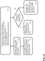
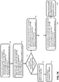
- Fig. 7A and 7B depict flow diagrams of processing consignments in a PUD network on the basis of weight and volume according to various embodiments of the invention.
- a scanning system may execute a first scan of a consignment at a predetermined time and location in which the weight, volume, and one or more images of consignment are produced. Based on the image data, a consignment ID is determined. Thereafter, the measured information and the consignment ID are formatted into a first (check-in) consignment profile. Then, the PUD system, e.g.
- the consignment information processor or the PUD network manager may use the consignment ID to link the information in the first check-in consignment profile with the with customer shipment information (step 703 ). If it is determined that the weight information deviates from the weight information in the shipment information, then the PUD system is triggered to correct the billing information. Hence, in this process, the real weight of the consignment is compare with the weight of the consignment as provided by the customer in the shipment information (step 704 ). As the price of the shipment is directly coupled to the weight of the shipment billing can be performed and corrected on the basis of the actual weight of the consignment as measured during check in.
- routing information may be generated on the basis of the measured consignment information the routing information representing a route through the depot to load position of a vehicle (e.g. a truck or a van) that is suitable for transporting the scanned consignment (steps 705 and 706 ).
- a vehicle e.g. a truck or a van
- routing information is generated on the basis of the measured consignment information for controlling routing of the consignment through a plurality of computer-controllable conveyor belts (steps 705 and 708 ). An example of such routing information will be described hereunder with reference to Fig. 8 and 9 .
- a scanning system may execute a first scan of a consignment at a predetermined time and depot location in which the weight, volume, and one or more images of consignment are produced. Based on the image data, a consignment ID is determined. Thereafter, the measured information and the consignment ID are formatted into a first (check-in) consignment profile. Thereafter, at a further time and depot location a second scan of the consignment may be executed and a second consignment profile may be generated.
- the monitor system may then check for deviations between the first and second consignment profile, e.g. deviations in the weight and/or volume. If one or more deviations are detected that are outside a particular error range, in one embodiment, the monitor system may analyses the image data of the consignment in order to localize changes in the shape of the consignment (step 718 ). Such changes in the shape may be an indication that the consignment is damaged. If deviations between the first and second consignment profile are found that are outside an predetermined error range, a warning flag may be set in the consignment database, the warning flag indicating that the physical characteristics of the consignment has changed during transportation which may be an indication that the consignment is damaged or the like. In that case, appropriate action can be taken.
- a warning flag may be set in the consignment database, the warning flag indicating that the physical characteristics of the consignment has changed during transportation which may be an indication that the consignment is damaged or the like. In that case, appropriate action can be taken.
- further scans may be executed at different depots thereby producing a plurality of consignment profiles associated with different times and locations during the transportation of the consignment (step 722 and 724 ).
- the check-in and check-out consignment profile may be compared and if there are no significant deviations between the two, the PUD system may determine that the transportation was successful in the sense that no damage occurred during transportation (step 726 ).
- the measured data during transportation can be used as evidence that the consignment was not damaged. This is especially important in case of special consignments that are difficult to handle so that the risk of damage during transport is not negligible.
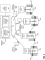
- Fig. 8 depicts a schematic of a scanning system for conveyable consignments according to an embodiment of the invention.
- Fig. 8 shows a schematic representation of an exemplary embodiment of a scanning system which is integrated with a conveyor belt.
- the scanning system comprises a plurality of convey belts 802, 804-806, 810,812, 830 1,2 wherein at least one of the convey belts 804 is a scale belt, i.e. a belt that includes a scale.
- the scale belt may be located between an in-belt 812 and an out-belt 802 and may comprise an in-feeder belt 806 , a scale belt 708 and an outfeeder belt 810 . Weight measurements may be performed by the scale belt 708 .
- a consignment may be provided via the in-feeder belt 806 onto the scale belt and when the consignment is moved above the scale, the belt may be shortly stopped so that the weight can be measured.
- Markings e.g. a code representing the consignment ID and, optionally, information about the destination location, are registered using a camera-based identification system 816 enabling reading markings from e.g. five sides (four sides, one top).
- Volume measurement is performed using a volume scanner 817 comprising lasers and mirrors enabling providing dimensioning data for both cuboid and non-cuboid objects.
- Software may be used, e.g. in computer system, to calculate a three-dimensional volume shape of the consignment as the smallest enclosing rectangular box in real time and may also be used to determine stackability of a consignment.
- a scanning system controller 814 is connected to the belts, imaging apparatus 816 and volume scanner apparatus 817 .
- the controller is configured to control the belts (the infeed belt, the scale belt and the outfeed belt) such that consignments are fed onto the scale belt with the correct gaps in between to allow appropriate measurement of the weight and volume.
- the scanning system controller may be further connected to a database 848 for storing the measured consignment information.
- the controller may send the measured consignment information as a consignment profile 850 via the network 807 to the monitoring system of the PUD system (not shown) in a similar way as described with reference to Fig. 5 .
- a plurality of chutes 830 1,2 are connected laterally to a side of the main conveyor belt 802 .
- chutes may also be provided at both sides of the main conveyor belt 802 .
- a chute is usually implemented as roller tables or slides forming a buffer for consignments collected for an associated destination.
- Each chute has an upstream end connecting to the main conveyor belt and a downstream end where consignments 818 1-7 can be loaded into cages or trucks 834 1,2 .
- the upstream ends of the chutes are within reach of ejectors 822 , 826 which can be moved by an electrometer 820 between a retracted position (ejector 822 in Fig. 8 ) and an ejecting position (ejector 826 in Fig. 8 ).
- an ejector 822,826 When an ejector 822,826 is activated it moves from the retracted position to the ejecting position to move a passing consignment 818 2,3 from the main conveyer onto the respective chute.
- the scanning system controller is connected to the ejectors and adapted to activate the ejectors when a predetermined consignment is passing by. Additionally, the controller has information including chute identifiers and associated destination information for each chute. Additionally, chutes may be associated with information on the weight, volume and/or dimensions of the consignments. Hence, the scanning system controller scans each consignment that passes by and uses the measured consignment information, i.e. the consignment ID, the weight and the volume, in order to allocate a consignment to a predetermined chute that is associated with destination information and measured consignment information (e.g.
- the scanning system controller will activate the respective ejector to move the consignment onto the chute.
- the chutes are provided with a terminal 832 1,2 where a cage or a truck can be logged on when the cage or truck is linked to the chute.
- the cage or truck can be logged off when the cage or truck is removed from the chute.
- the controller is programmed to receive the log-on and log-off data. Logging on includes input of a cage or truck identity and linking the cage or truck identity to a chute identity of the selected chute.
- the controller is also programmed to keep a record of consignment identities of consignment that have been moved onto selected chutes in a time period between logging on and logging off of the cage or truck.
- Fig. 9 depicts a schematic of scanning process using a scanning system according to an embodiment of the invention.
- the flow chart of Fig. 9 illustrates the individual steps of a method for sorting and handling consignments for transhipment using a scanning system.
- Fig. 9 is explained with reference to the system of Fig. 8 .
- Consignments may be collected on the conveyer belt wherein each consignment is labelled with a unique scan-readable code, such as a barcode.
- the scanning system including the scale belt, scans the consignments that pass by.
- the weight, volume, dimensions and consignment ID may be determined.
- the scanning system controller may store the measured consignment information in a database and send the information as a consignment profile (the physical status of the consignment at a predetermined time and location) to the monitoring system of the PUD system.
- the controller has information on the chute identifiers and destination information for each chute. Additionally, the chutes may be associated with weight, volume and/or dimensions of the consignments. For example, one shut may collect consignments within a predetermined range of weights and/or volumes. Hence, the chute identities are associated with destination information, weight, volume and dimensions (step 903 ) .
- the controller may link the consignment identity to a chute identity of a chute on the basis of destination, weight, volume and dimensions (step 904 ).
- a consignment passes a selected chute 7 (step 105 ) and the controller activates the ejector associated with the selected chute (step 106 ).
- the ejector moves the consignment from the conveyer onto the chute (step 107 ).
- the consignment is subsequently moved from the chute into a transportation means, e.g. a cage or a truck (step 108 ).
- the cage or truck When a cage or a truck is positioned at the downstream end of a chute, the cage or truck is configured to identify itself (log on) to the controller on the basis of an identifier (e.g. a cage identifier or a truck identifier) (steps 909 ). In response the controller may link the cage or truck identity to a chute identity of the chute (step 910 ). Subsequently for each consignment that is moved to the chute the controller links the consignment identity to the cage or truck identity (step 911 ). This way the controller may determine which individual consignments are within a given cage or truck and to trace which cage or truck contains a given consignment. After a time period, e.g., after filling the cage or the truck, the cage is logged off with the controller and a new cage or truck can identify itself to the controller.
- an identifier e.g. a cage identifier or a truck identifier
- Fig. 10 provides a schematic illustration of a data processing system 1000 operable to implement one or more aspects of the present invention.
- the system 1000 includes a block diagram illustrating an exemplary data processing system that may be used in as described in this disclosure.
- Data processing system 1000 may include at least one processor 1002 coupled to memory elements 1004 through a system bus 1006 .
- the data processing system may store program code within memory elements 1004 .
- processor 1002 may execute the program code accessed from memory elements 1004 via system bus 1006.
- data processing system may be implemented as a computer that is suitable for storing and/or executing program code. It should be appreciated, however, that data processing system 1000 may be implemented in the form of any system including a processor and memory that is capable of performing the functions described within this specification.
- Memory elements 1004 may include one or more physical memory devices such as, for example, local memory 1008 and one or more bulk storage devices 1010 .
- Local memory may refer to random access memory or other non-persistent memory device(s) generally used during actual execution of the program code.
- a bulk storage device may be implemented as a hard drive or other persistent data storage device.
- the processing system 1000 may also include one or more cache memories (not shown) that provide temporary storage of at least some program code in order to reduce the number of times program code must be retrieved from bulk storage device 1010 during execution.
- I/O devices depicted as input device 1012 and output device 1014 optionally can be coupled to the data processing system.
- input device may include, but are not limited to, for example, a keyboard, a pointing device such as a mouse, or the like.
- output device may include, but are not limited to, for example, a monitor or display, speakers, or the like.
- Input device and/or output device may be coupled to data processing system either directly or through intervening I/O controllers.
- a network adapter 1016 may also be coupled to data processing system to enable it to become coupled to other systems, computer systems, remote network devices, and/or remote storage devices through intervening private or public networks.
- the network adapter may comprise a data receiver for receiving data that is transmitted by said systems, devices and/or networks to said data and a data transmitter for transmitting data to said systems, devices and/or networks.
- Modems, cable modems, and Ethernet cards are examples of different types of network adapter that may be used with data processing system.
- memory elements 1004 may store an application 1018 .
- data processing system 1000 may further execute an operating system (not shown) that can facilitate execution of the application.
- Application being implemented in the form of executable program code, can be executed by data processing system 1000 , e.g., by processor 1002 . Responsive to executing application, data processing system may be configured to perform one or more operations to be described herein in further detail.
Landscapes
- Business, Economics & Management (AREA)
- Economics (AREA)
- Physics & Mathematics (AREA)
- Engineering & Computer Science (AREA)
- General Physics & Mathematics (AREA)
- Human Resources & Organizations (AREA)
- Development Economics (AREA)
- Entrepreneurship & Innovation (AREA)
- Marketing (AREA)
- Operations Research (AREA)
- Quality & Reliability (AREA)
- Strategic Management (AREA)
- Tourism & Hospitality (AREA)
- General Business, Economics & Management (AREA)
- Theoretical Computer Science (AREA)
- Mathematical Physics (AREA)
- Length Measuring Devices By Optical Means (AREA)
- Warehouses Or Storage Devices (AREA)
Priority Applications (1)
| Application Number | Priority Date | Filing Date | Title |
|---|---|---|---|
| EP25222527.1A EP4711995A2 (de) | 2016-06-29 | 2017-06-29 | Verarbeitung von sendungen in lade- und vertriebsnetzen auf basis von gewicht- und volumeninformationen |
Applications Claiming Priority (1)
| Application Number | Priority Date | Filing Date | Title |
|---|---|---|---|
| NL1041965A NL1041965B1 (en) | 2016-06-29 | 2016-06-29 | Processing consignments in a pick-up and delivery network on the basis of weight and volume Information |
Related Child Applications (1)
| Application Number | Title | Priority Date | Filing Date |
|---|---|---|---|
| EP25222527.1A Division EP4711995A2 (de) | 2016-06-29 | 2017-06-29 | Verarbeitung von sendungen in lade- und vertriebsnetzen auf basis von gewicht- und volumeninformationen |
Publications (4)
| Publication Number | Publication Date |
|---|---|
| EP3264346A2 true EP3264346A2 (de) | 2018-01-03 |
| EP3264346A3 EP3264346A3 (de) | 2018-04-04 |
| EP3264346B1 EP3264346B1 (de) | 2025-12-24 |
| EP3264346C0 EP3264346C0 (de) | 2025-12-24 |
Family
ID=57208332
Family Applications (2)
| Application Number | Title | Priority Date | Filing Date |
|---|---|---|---|
| EP17178786.4A Active EP3264346B1 (de) | 2016-06-29 | 2017-06-29 | Verarbeitung von sendungen in lade- und vertriebsnetzen auf basis von gewicht- und volumeninformationen |
| EP25222527.1A Pending EP4711995A2 (de) | 2016-06-29 | 2017-06-29 | Verarbeitung von sendungen in lade- und vertriebsnetzen auf basis von gewicht- und volumeninformationen |
Family Applications After (1)
| Application Number | Title | Priority Date | Filing Date |
|---|---|---|---|
| EP25222527.1A Pending EP4711995A2 (de) | 2016-06-29 | 2017-06-29 | Verarbeitung von sendungen in lade- und vertriebsnetzen auf basis von gewicht- und volumeninformationen |
Country Status (2)
| Country | Link |
|---|---|
| EP (2) | EP3264346B1 (de) |
| NL (3) | NL1041965B1 (de) |
Cited By (1)
| Publication number | Priority date | Publication date | Assignee | Title |
|---|---|---|---|---|
| CN112938011A (zh) * | 2021-03-12 | 2021-06-11 | 上汽通用五菱汽车股份有限公司 | 一种基于无序混合纸箱的机器人码垛系统及方法 |
Citations (1)
| Publication number | Priority date | Publication date | Assignee | Title |
|---|---|---|---|---|
| US20140048383A1 (en) * | 2012-08-14 | 2014-02-20 | Electronics And Telecommunications Research Institute | Package automation apparatus |
Family Cites Families (14)
| Publication number | Priority date | Publication date | Assignee | Title |
|---|---|---|---|---|
| US3935913A (en) * | 1974-10-18 | 1976-02-03 | Howe Richardson Scale Company | Platform weighing scale |
| US6015039A (en) * | 1997-02-04 | 2000-01-18 | United Parcel Service Of America, Inc. | High speed tilted belt sorter |
| US6292710B1 (en) * | 1999-12-20 | 2001-09-18 | United Parcel Service Of America, Inc. | Conveyor having variable speed control |
| JP2002048624A (ja) * | 2000-05-25 | 2002-02-15 | Unipulse Corp | 計量装置 |
| ES2297060T3 (es) * | 2003-02-01 | 2008-05-01 | Sick Ag | Procedeimiento para el funcionamiento de un sensor optico. |
| US20070237356A1 (en) * | 2006-04-07 | 2007-10-11 | John Dwinell | Parcel imaging system and method |
| TW200813892A (en) * | 2006-04-24 | 2008-03-16 | Abb Ab | Automatic system for processing inspection data |
| WO2007133675A2 (en) * | 2006-05-11 | 2007-11-22 | Loadstar Sensors, Inc. | Capacitive force-measuring device based load sensing platform |
| DE102007038836A1 (de) * | 2007-08-16 | 2009-02-19 | BIBA - Bremer Institut für Produktion und Logistik GmbH | Vorrichtung und Verfahren zur Bearbeitung von Gegenständen mit aufgebrachten Informationen |
| US9841314B2 (en) * | 2008-08-29 | 2017-12-12 | United Parcel Service Of America, Inc. | Systems and methods for freight tracking and monitoring |
| JP4797080B2 (ja) * | 2009-04-03 | 2011-10-19 | 株式会社タニタ | 重量計 |
| US8046312B2 (en) * | 2009-05-21 | 2011-10-25 | Accenture Global Services Limited | Enhanced postal data modeling framework |
| KR20120063378A (ko) * | 2010-12-07 | 2012-06-15 | 한국전자통신연구원 | 운송물 처리 시스템 및 그 방법 |
| CA3002450C (en) * | 2013-06-19 | 2020-12-15 | United States Postal Service | System and method for providing real-time tracking of items in a distribution network |
-
2016
- 2016-06-29 NL NL1041965A patent/NL1041965B1/en not_active IP Right Cessation
-
2017
- 2017-06-29 EP EP17178786.4A patent/EP3264346B1/de active Active
- 2017-06-29 EP EP25222527.1A patent/EP4711995A2/de active Pending
- 2017-12-29 NL NL2020208A patent/NL2020208B1/en not_active IP Right Cessation
- 2017-12-29 NL NL2020207A patent/NL2020207B1/en not_active IP Right Cessation
Patent Citations (1)
| Publication number | Priority date | Publication date | Assignee | Title |
|---|---|---|---|---|
| US20140048383A1 (en) * | 2012-08-14 | 2014-02-20 | Electronics And Telecommunications Research Institute | Package automation apparatus |
Cited By (2)
| Publication number | Priority date | Publication date | Assignee | Title |
|---|---|---|---|---|
| CN112938011A (zh) * | 2021-03-12 | 2021-06-11 | 上汽通用五菱汽车股份有限公司 | 一种基于无序混合纸箱的机器人码垛系统及方法 |
| CN112938011B (zh) * | 2021-03-12 | 2023-03-24 | 上汽通用五菱汽车股份有限公司 | 一种基于无序混合纸箱的机器人码垛系统及方法 |
Also Published As
| Publication number | Publication date |
|---|---|
| EP3264346B1 (de) | 2025-12-24 |
| NL1041965B1 (en) | 2018-01-05 |
| NL2020207A (en) | 2018-04-30 |
| NL2020208A (en) | 2018-04-16 |
| EP3264346C0 (de) | 2025-12-24 |
| NL2020208B1 (en) | 2018-11-06 |
| EP4711995A2 (de) | 2026-03-18 |
| EP3264346A3 (de) | 2018-04-04 |
| NL2020207B1 (en) | 2018-11-06 |
Similar Documents
| Publication | Publication Date | Title |
|---|---|---|
| US12443921B2 (en) | Item transitions | |
| US12211004B2 (en) | Detecting inventory changes | |
| US11709464B1 (en) | Dynamic adjustment of a presentation area | |
| US11775930B1 (en) | Bin content verification | |
| US9965739B2 (en) | Systems and methods for freight tracking and monitoring | |
| US9120621B1 (en) | Verifying bin content in an automated materials handling facility | |
| US9841314B2 (en) | Systems and methods for freight tracking and monitoring | |
| US8386397B1 (en) | System and method for constraint-based reduction of a solution space for vehicle routing | |
| US12165480B1 (en) | Hybrid retail environments | |
| NL2020208B1 (en) | Processing non-conveyable consignments in a pick-up and delivery network on the basis of weight and volume information | |
| US11905125B1 (en) | Parcel cart loading system | |
| WO2025184739A1 (en) | Pallet processing system | |
| NL2016975B1 (en) | Method and system for receiving a request to transport a consignment | |
| KR102808800B1 (ko) | 물류 오피킹 방지 방법 및 시스템 | |
| KR20240108356A (ko) | 비전 기반의 화물 분류 시스템 및 방법 | |
| KR20240159991A (ko) | 감모율 저감 물류시스템 | |
| JP2017065888A (ja) | ロールボックスパレットの配送情報管理サーバ、配送情報処理システム及び荷物積載ロールボックスパレットの配送方法 |
Legal Events
| Date | Code | Title | Description |
|---|---|---|---|
| PUAI | Public reference made under article 153(3) epc to a published international application that has entered the european phase |
Free format text: ORIGINAL CODE: 0009012 |
|
| STAA | Information on the status of an ep patent application or granted ep patent |
Free format text: STATUS: THE APPLICATION HAS BEEN PUBLISHED |
|
| AK | Designated contracting states |
Kind code of ref document: A2 Designated state(s): AL AT BE BG CH CY CZ DE DK EE ES FI FR GB GR HR HU IE IS IT LI LT LU LV MC MK MT NL NO PL PT RO RS SE SI SK SM TR |
|
| AX | Request for extension of the european patent |
Extension state: BA ME |
|
| PUAL | Search report despatched |
Free format text: ORIGINAL CODE: 0009013 |
|
| RIC1 | Information provided on ipc code assigned before grant |
Ipc: G06Q 10/08 20120101AFI20180222BHEP |
|
| AK | Designated contracting states |
Kind code of ref document: A3 Designated state(s): AL AT BE BG CH CY CZ DE DK EE ES FI FR GB GR HR HU IE IS IT LI LT LU LV MC MK MT NL NO PL PT RO RS SE SI SK SM TR |
|
| AX | Request for extension of the european patent |
Extension state: BA ME |
|
| STAA | Information on the status of an ep patent application or granted ep patent |
Free format text: STATUS: REQUEST FOR EXAMINATION WAS MADE |
|
| 17P | Request for examination filed |
Effective date: 20190129 |
|
| RBV | Designated contracting states (corrected) |
Designated state(s): AL AT BE BG CH CY CZ DE DK EE ES FI FR GB GR HR HU IE IS IT LI LT LU LV MC MK MT NL NO PL PT RO RS SE SI SK SM TR |
|
| STAA | Information on the status of an ep patent application or granted ep patent |
Free format text: STATUS: EXAMINATION IS IN PROGRESS |
|
| 17Q | First examination report despatched |
Effective date: 20210222 |
|
| GRAP | Despatch of communication of intention to grant a patent |
Free format text: ORIGINAL CODE: EPIDOSNIGR1 |
|
| STAA | Information on the status of an ep patent application or granted ep patent |
Free format text: STATUS: GRANT OF PATENT IS INTENDED |
|
| INTG | Intention to grant announced |
Effective date: 20250722 |
|
| GRAS | Grant fee paid |
Free format text: ORIGINAL CODE: EPIDOSNIGR3 |
|
| GRAA | (expected) grant |
Free format text: ORIGINAL CODE: 0009210 |
|
| STAA | Information on the status of an ep patent application or granted ep patent |
Free format text: STATUS: THE PATENT HAS BEEN GRANTED |
|
| AK | Designated contracting states |
Kind code of ref document: B1 Designated state(s): AL AT BE BG CH CY CZ DE DK EE ES FI FR GB GR HR HU IE IS IT LI LT LU LV MC MK MT NL NO PL PT RO RS SE SI SK SM TR |
|
| REG | Reference to a national code |
Ref country code: CH Ref legal event code: F10 Free format text: ST27 STATUS EVENT CODE: U-0-0-F10-F00 (AS PROVIDED BY THE NATIONAL OFFICE) Effective date: 20251224 Ref country code: GB Ref legal event code: FG4D |
|
| REG | Reference to a national code |
Ref country code: DE Ref legal event code: R096 Ref document number: 602017093244 Country of ref document: DE |
|
| U01 | Request for unitary effect filed |
Effective date: 20251230 |
|
| U07 | Unitary effect registered |
Designated state(s): AT BE BG DE DK EE FI FR IT LT LU LV MT NL PT RO SE SI Effective date: 20260112 |
|
| PG25 | Lapsed in a contracting state [announced via postgrant information from national office to epo] |
Ref country code: NO Free format text: LAPSE BECAUSE OF FAILURE TO SUBMIT A TRANSLATION OF THE DESCRIPTION OR TO PAY THE FEE WITHIN THE PRESCRIBED TIME-LIMIT Effective date: 20260324 |
|
| PG25 | Lapsed in a contracting state [announced via postgrant information from national office to epo] |
Ref country code: HR Free format text: LAPSE BECAUSE OF FAILURE TO SUBMIT A TRANSLATION OF THE DESCRIPTION OR TO PAY THE FEE WITHIN THE PRESCRIBED TIME-LIMIT Effective date: 20251224 |
|
| PG25 | Lapsed in a contracting state [announced via postgrant information from national office to epo] |
Ref country code: RS Free format text: LAPSE BECAUSE OF FAILURE TO SUBMIT A TRANSLATION OF THE DESCRIPTION OR TO PAY THE FEE WITHIN THE PRESCRIBED TIME-LIMIT Effective date: 20260324 |