EP3265202B1 - Dispositif de filtration de fluides - Google Patents
Dispositif de filtration de fluides Download PDFInfo
- Publication number
- EP3265202B1 EP3265202B1 EP16707388.1A EP16707388A EP3265202B1 EP 3265202 B1 EP3265202 B1 EP 3265202B1 EP 16707388 A EP16707388 A EP 16707388A EP 3265202 B1 EP3265202 B1 EP 3265202B1
- Authority
- EP
- European Patent Office
- Prior art keywords
- fluid
- filter
- chamber
- control chamber
- post
- Prior art date
- Legal status (The legal status is an assumption and is not a legal conclusion. Google has not performed a legal analysis and makes no representation as to the accuracy of the status listed.)
- Active
Links
Images



Classifications
-
- B—PERFORMING OPERATIONS; TRANSPORTING
- B01—PHYSICAL OR CHEMICAL PROCESSES OR APPARATUS IN GENERAL
- B01D—SEPARATION
- B01D29/00—Filters with filtering elements stationary during filtration, e.g. pressure or suction filters, not covered by groups B01D24/00 - B01D27/00; Filtering elements therefor
- B01D29/50—Filters with filtering elements stationary during filtration, e.g. pressure or suction filters, not covered by groups B01D24/00 - B01D27/00; Filtering elements therefor with multiple filtering elements, characterised by their mutual disposition
- B01D29/52—Filters with filtering elements stationary during filtration, e.g. pressure or suction filters, not covered by groups B01D24/00 - B01D27/00; Filtering elements therefor with multiple filtering elements, characterised by their mutual disposition in parallel connection
-
- B—PERFORMING OPERATIONS; TRANSPORTING
- B01—PHYSICAL OR CHEMICAL PROCESSES OR APPARATUS IN GENERAL
- B01D—SEPARATION
- B01D29/00—Filters with filtering elements stationary during filtration, e.g. pressure or suction filters, not covered by groups B01D24/00 - B01D27/00; Filtering elements therefor
- B01D29/50—Filters with filtering elements stationary during filtration, e.g. pressure or suction filters, not covered by groups B01D24/00 - B01D27/00; Filtering elements therefor with multiple filtering elements, characterised by their mutual disposition
- B01D29/56—Filters with filtering elements stationary during filtration, e.g. pressure or suction filters, not covered by groups B01D24/00 - B01D27/00; Filtering elements therefor with multiple filtering elements, characterised by their mutual disposition in series connection
-
- B—PERFORMING OPERATIONS; TRANSPORTING
- B01—PHYSICAL OR CHEMICAL PROCESSES OR APPARATUS IN GENERAL
- B01D—SEPARATION
- B01D29/00—Filters with filtering elements stationary during filtration, e.g. pressure or suction filters, not covered by groups B01D24/00 - B01D27/00; Filtering elements therefor
- B01D29/62—Regenerating the filter material in the filter
- B01D29/66—Regenerating the filter material in the filter by flushing, e.g. counter-current air-bumps
- B01D29/665—Regenerating the filter material in the filter by flushing, e.g. counter-current air-bumps by using pistons
-
- B—PERFORMING OPERATIONS; TRANSPORTING
- B01—PHYSICAL OR CHEMICAL PROCESSES OR APPARATUS IN GENERAL
- B01D—SEPARATION
- B01D29/00—Filters with filtering elements stationary during filtration, e.g. pressure or suction filters, not covered by groups B01D24/00 - B01D27/00; Filtering elements therefor
- B01D29/62—Regenerating the filter material in the filter
- B01D29/66—Regenerating the filter material in the filter by flushing, e.g. counter-current air-bumps
- B01D29/668—Regenerating the filter material in the filter by flushing, e.g. counter-current air-bumps with valves, e.g. rotating valves for coaxially placed filtering elements
-
- B—PERFORMING OPERATIONS; TRANSPORTING
- B01—PHYSICAL OR CHEMICAL PROCESSES OR APPARATUS IN GENERAL
- B01D—SEPARATION
- B01D2201/00—Details relating to filtering apparatus
- B01D2201/08—Regeneration of the filter
-
- B—PERFORMING OPERATIONS; TRANSPORTING
- B01—PHYSICAL OR CHEMICAL PROCESSES OR APPARATUS IN GENERAL
- B01D—SEPARATION
- B01D2201/00—Details relating to filtering apparatus
- B01D2201/16—Valves
Definitions
- the invention relates to a system for filtering fluids with the features in the preamble of claim 1.
- the high viscosity of the heavy oil makes both the backwashing process for the primary filter and the filtration process that has to be carried out for processing by means of the aftertreatment device, which is connected downstream of the primary filter, more difficult.
- the US 2005/0170492 A1 discloses a system for filtering fluids, with a primary filter which has at least one filter element through which flow can flow in one direction during the filtration process and through which flow can flow in the opposite direction for a backwash process, with an aftertreatment device connected downstream of the primary filter for processing the backwash quantities released by it, which has at least one filter chamber with fluid inlet and fluid outlet and with at least one aftertreatment filter element, and with a control device for feeding the respective backwash amount in portions to the assignable aftertreatment filter element.
- the invention is based on the task of providing a filtration system that not only ensures efficient backwashing in a primary filter, even with highly viscous fluids, but also enables effective processing of the backwashing quantities emitted by the primary filter.
- this object is achieved by a filtration system which has the features of claim 1 in its entirety.
- the system according to the invention is characterized in that the control device has a control chamber with a first and a second fluid chamber, of which the first is used to receive the respective backwash amount and the second fluid chamber with a compressed gas, in particular in the form of Compressed air can be acted upon with a predeterminable working pressure; and that the first and second fluid spaces of the control chamber are separated by a separating piston.
- the filter material of the respective aftertreatment filter element can be flown through by a backwash quantity which is under a predetermined pressure.
- the working pressure in the second fluid space can be set to a value that is optimal for the post-treatment filtration process, so that even with heavy oil applications, such as ship diesel engines, the treated rinsing oil that occurs as a filtrate is largely free of contamination.
- the first and second fluid spaces of the control chamber are separated by a separating piston.
- the flushing oil is neither enriched with working gas nor cooled by the gas entry.
- a large part of the flushing oil prepared by the aftertreatment device can be returned to the unfiltrate side of the primary filter, which contributes to reducing the fuel consumption of the ship concerned.
- a smaller amount of ultimately remaining flushing oil which has to be collected in the ship and disposed of in the port.
- a valve control is provided for supplying and removing the pressurized gas to and from the second fluid space of the control chamber, in particular in the form of an electrically controllable 3/2-way valve which is connected to the second fluid space of the control chamber in a way that carries pressurized gas.
- the first fluid space of the control chamber can be permanently connected to the unfiltrate side of the respective filter element within the filter chamber in a fluid-carrying manner, the filtrate side, which is separated from its unfiltrate side via the respective filter element, at least temporarily a fluid-carrying connection to the fluid outlet having.
- a further valve control device can be connected between the filtrate side of the respective filter element within the filter chamber and the fluid outlet in the relevant fluid connection, in particular in the form of a preferably spring-loaded check valve. This prevents the aftertreatment device from running empty.
- a further, third valve control device can be present on the side of the fluid inlet, which controls the entry of the respective backwash quantity coming from the primary filter into the aftertreatment device.
- a motor valve can advantageously be provided here. If the aftertreatment device is downstream of a primary filter, as shown in DE 10 2011 100 518 A1 is disclosed, the motor valve, which is arranged at the flushing quantity outlet of this primary filter and denoted there by 31 in the description, can form the valve control device at the fluid inlet.
- the aftertreatment device can be designed such that, viewed in the fluid flow direction, the control chamber is connected upstream of the filter chamber with the respective filter element or that the filter chamber with the respective filter element is arranged concentrically to the control chamber and encompasses it.
- the arrangement can particularly advantageously be such that an energy store, preferably in the form of a tension spring, engages the separating piston and that the energy store extends through the second fluid space of the control chamber.
- the separating piston can be moved by means of the tension spring in the direction of increasing the volume of the first fluid space of the control chamber, so that a kind of suction effect is generated in the control chamber and the filter chamber and the control chamber fills with a backwash quantity released by the upstream primary filter .
- the aftertreatment filtration process can then take place at the predetermined, optimal pressure level.
- the aftertreatment device has a connector that can be connected to the primary filter, with the fluid inlet for backwash quantities and the fluid outlet for aftertreated backwash quantities, the connector forming the carrier for the control chamber and two filter chambers that are jointly assigned to it and that are arranged on both sides next to the control chamber that within the connection part, the first fluid space of the control chamber is permanently connected to the unfiltrate side of each of the filter chambers, the filtrate sides of which are at least temporarily connected to the fluid outlet within the connection part.
- a heater and / or an electronic pressure and / or temperature measuring device is preferably arranged at least in the fluid-carrying connection area between the control chamber and the filter chamber. In this way, depending on the temperature and viscosity of the backwashing quantity coming from the primary filter, the temperature suitable for the optimal filtration process and the working pressure of the control chamber can be set.
- the aftertreatment device can be connected to the primary filter in such a way that the amount of fluid occurring at the fluid outlet of the aftertreatment device can be returned to the unfiltrate side of the primary filter, forming a closed circuit.
- This return is particularly advantageous in marine heavy oil applications, where it is a requirement that the flushing oil that occurs during processing must be collected in the ship. By returning a large part of the flushing oil that occurs, which also indirectly reduces fuel consumption on ships, less flushing oil is generated, which ultimately has to be disposed of in the port.
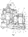
- the first embodiment of the system according to the invention shown corresponds to the primary filter, the main housing of which in FIG Fig. 1 at 2, the backwash filter device disclosed in the above-mentioned document WO 2012/150011 A1 and to which reference is made.
- the backwash filter device disclosed in the above-mentioned document WO 2012/150011 A1 and to which reference is made.
- the simplified representation of the Fig. 1 therefore not all details of this known device are shown, but only the details of this backwash filter device which are essential for understanding the system according to the invention and which, as a primary filter, is part of the system according to the invention.
- different types of backwash filter devices are provided as the primary filter such as those in the document already mentioned DE 10 2011 100 518 A1 disclosed device.
- a hydropneumatic piston accumulator 18 is provided in the main housing 2, the piston 20 of which separates a gas side 22 from a fluid side 24.
- FIG. 1 shows the piston 20 in a position in which it is fed to the gas side 22 from a purging gas tank 12 containing compressed air via a membrane valve 14 and a purging gas line 16, so that the piston 20 in Fig. 1 is driven upwards.
- the piston 20 has supplied this as pressurized rinsing liquid from the fluid side 24, which was previously filled with filtrate, via a backwash guide 26 to the chamber connection (not shown) of a selected element chamber 4, the filter element of which is to be backwashed.
- the desired element chamber 4 to be backwashed is selected by setting the rotary position of the piston accumulator 18 by means of a rotary drive 6 assigned to it.
- the backwash quantity with the detached impurities emerges from the clean-side chamber connection 28 from the element chamber 4 and leaves the primary filter via a backwash outlet 32, from where it reaches the fluid inlet 3 of the associated aftertreatment device 36 via a pipe connector 34.
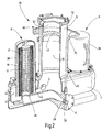
- the base body of the aftertreatment device 36 is formed by a connection part 1, which forms the carrier for two aftertreatment filter chambers 11 and a control chamber 9 forming the aftertreatment control device, which is located in the central area of the connection part 1 between the two filter chambers 11 on the top of the connection part 1 is arranged.
- the control chamber 9, like the chamber housing 38 of the filter chambers 11, is flanged to the upper cover wall 40 of the connection part 1 in such a way that the control chamber 9 and chamber housing 38 of the filter chambers are open to the inner cavity located under the cover wall 40, which has an between the filter chambers 11 and the control chamber 9 forms a continuous channel 13.
- the fluid inlet 3 opens into this channel 13 and is connected to the backwash outlet 32 of the primary filter via the pipe connection 34.
- a valve control device for example in the form of a spring-loaded non-return valve, which opens during the backwashing process due to the pressure of the backwashing quantity that is supplied from the piston accumulator 18.
- a motor-operated ball valve can be provided in the pipe connection 34, for example that in the document mentioned WO 2012/150011 A1 with 53 designated ball valve of the primary filter.
- an inner tube 42 runs in the bottom area of the interior of the connection part 1 in the horizontal direction between the filter chambers 11. At both ends of the inner tube 42 there is an opening, the edge of which forms an element receptacle 46 on which a filter element located in the associated filter chamber 11 is located 19 is received such that the inner filter cavity 17 of each filter element 19 is in fluid communication with the inner tube 42.
- the inner pipe 42 thereby forms the filtrate side from which the treated backwash flow reaches the fluid outlet 5, where a check valve 29 is also located a closing body 30 is located. In order to prevent the system from running empty, this can be slightly preloaded into the closed position.
- the control chamber 9 flanged to the top wall 40 of the connection part 1 is formed by a circular cylinder which, together with a separating piston 43 which can be moved longitudinally in it, forms a hydropneumatic piston accumulator which is closed at the upper end by a cover 72.
- the separating piston 43 separates a first fluid chamber 51, which is in connection with the channel 13 in the connection part 1 and therefore receives a backwash amount flowing in from the fluid inlet 3, from a second fluid chamber 53, which is for a pressure medium that can be acted upon by the separating piston 43, in the present case from Compressed air, is provided.
- valve control device 65 On the cover 72 closing off the second fluid space 43 there is a valve control device 65, by means of which the pressure level in the second fluid space 53 of the control chamber 9 can be controlled in such a way that successive treatment filtrations are carried out in portions, each with a backwashing amount that the control chamber 9 through stroke movements of the piston 43 makes available, which are generated by a working pressure prevailing in the second fluid space 53.
- valve control device 65 has an electrically controllable 3/2-way valve 67, from which a connection 69 leads to the second fluid space 53 of the control chamber 9.
- a second connection 71 leads via an adjustable throttle 73 to the purge gas tank 12 serving as a compressed air source ( Fig. 1 ) of the primary filter.
- a pressure relief line 75 which is connected to the connection line 69 and leads to the fluid outlet 5, enables pressure to be released in the second fluid space 53.
- the check valve located in the pipe connection 34 Due to the pressure of the unfiltrate generated by the piston accumulator, the check valve located in the pipe connection 34 has closed, or a possibly provided motor valve has been closed when a backwashing process of the primary filter is completed.
- the preparation-filtration process takes place under the filtration pressure generated by the working pressure in the second fluid space 53 of the control chamber 9, the filtrate formed flowing through the inner tube 42 from the inner cavity 17 of the filter elements 19, which forms the filtrate side, to the fluid outlet 5 with the check valve 29 open.
- the chamber housings 38 of the filter chambers 11 have a slightly conically tapering course in the direction of their closed upper end, so that the flow cross-section of the unfiltrate side 44 decreases from the lower inflow point upwards, which ensures a homogeneous flow through the Filter material 21 result in favorable flow conditions.
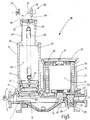
- the Figures 5 to 7 show the aftertreatment device 36 of a second embodiment of the system according to the invention.
- the control chamber 9 is located on the top of the connection part 1 in the vicinity of the fluid inlet 3 and the only one filter chamber 11 is offset on the connection part 1 towards the fluid outlet 5, which is located on the end of the connection part 1 opposite the fluid inlet.
- the fluid inlet 3 is preceded by a symbolized motor valve 7, which can be formed by the motor valve located at the backwash outlet 32 of the primary filter, which is described in the document mentioned WO 2012/150011 A1 With 53 is designated.
- a channel 13 adjoins the fluid inlet 3 in the connection part 1, which extends in the direction of the fluid outlet 5, but ends at a distance therefrom in the central region of the filter chamber 11 and forms an inlet 15 at this end, which forms a fluid path into the inner filter cavity 17 of the filter element 19 located in the filter chamber 11.
- the filter element 19 surrounding the inner cavity 17 with its filter material 21 forming a hollow cylinder can be installed and / or exchanged in the filter chamber 11 via a removable housing cover 23.
- the space 25 which forms the filtrate side during the preparation-filtration process and which surrounds the filter material 21 is connected to the fluid outlet 5 via a longitudinal channel 27 which extends in the area of the filter chamber 11 along the top of the connection part 1, the release or the closure of this Connection can be blocked or released by a further valve control device which, in the example shown, is formed by a check valve 29.
- a check valve 29 This is spring-controlled and has a closing body 30 which is pushed into the in Fig. 5 The closed position shown is biased, in which the closing body 30 rests against a valve plate 33 and closes the opening thereof.
- the check valve 29 is set to an opening pressure of approximately 0.5 bar, so that a corresponding, low preload pressure is maintained in the fluid system of the device and idling is prevented.
- a ventilation hole 35 which forms into the inner filter cavity 17 forming the unfiltrate side, and a ventilation hole 37 which opens into the filtrate space 25 are provided in the housing cover 23. Ventilation elements of conventional design assigned to the bores 35, 37 are not shown.
- the main part of the control chamber 9 is a circular cylinder which, with its lower end 41 in the drawing, is flanged to the connection part 1 in the vicinity of the fluid inlet 3 and is open to the channel 13.
- the cylinder forms with the separating piston 43, which can be moved longitudinally in it, a hydropneumatic piston accumulator which is closed at the upper end 45 of the cylinder by a dome 47 with a tapered diameter.
- the lower end of the dome 47 forms a stop surface 49 at the end 45 of the cylinder to limit the movement of the separating piston 43 upwards in the drawing.
- the separating piston 43 separates a first fluid space 51, which is connected to the channel 13 and therefore receives a backwash amount flowing in from the fluid inlet 3, from a second fluid space 53, which is used for a pressure medium that can be acted upon by the separating piston 43 present case of compressed air, is provided.
- the dome 47 is closed at the upper end by a closure plate 55, on the inside of which there is an anchorage 57 for a tension spring 59, the lower end of which engages the separating piston 43 via an anchorage 61 and biases it for a movement in which the volume of the first fluid space 51 enlarged.
- connection point 63 for the valve control device 65 by means of which the pressure level in the second fluid space 53 of the control chamber 9 can be controlled in such a way that successive treatment filtrations are carried out in portions, each with a backwash amount that the control chamber 9 corresponding to the stroke movements of the separating piston 43 provides.
- the valve control device 65 has an electrically controllable 3/2-way valve 67, from which a connection line 69 leads to the connection point 63 on the control chamber 9.
- a second connection line 71 leads via an adjustable throttle 73 to a compressed air source.
- a third connection line 75 of the valve 67 enables pressure relief to the outside.
- the Fig. 5 shows the initial situation in which the channel 13 and the filter chamber 11 are filled with unfiltrate and vented by means of the bores 35 and 37.
- the second fluid space 53 is supplied with compressed air via the valve 67 filled, so that the separating piston 43 is acted upon by pressure and against the force of the extended tension spring 59 in the in Fig. 5 shown, lower position is held. If backwashing is triggered in the upstream primary filter, then, with the engine valve 7 open, the 3/2-way valve 65 is switched over in order to discharge the compressed air from the second fluid chamber 53.
- the tension spring 59 now pulls the relieved separating piston 43 into the in Fig.
- both the filter chamber 11 and the cylinder of the control chamber 9 are filled with backwashing liquid.
- the valve 65 is switched over in such a way that compressed air flows in via the throttle 73 and loads the separating piston 43 in such a way that it moves downward against the force of the tension spring 59.
- the amount of backwashing liquid located in the cylinder of the control chamber 9 is expelled and conveyed to the filter chamber 11 via the channel 13 and the inlet 15.
- the filtrate formed after flowing through the filter material 21 flows out of the filtrate space 25 surrounding the filter element 19 to the longitudinal channel 27. Since the filtration process takes place under the filtration pressure generated by the working pressure in the second fluid space 53 of the control chamber 9, the check valve 29 opens the connection to the fluid outlet 5.
- the flow profile resulting from the filtration process is shown in FIG Fig. 7 indicated by flow arrows 79.
- the filtration pressure can be adjusted for optimal adaptation to the nature and viscosity of the backwashing liquid.
- favorable temperature control can be achieved by means of a thermal contact with channel 13 Achieve standing heating element 81, wherein an electrical supply of the heating element 81 or the supply by means of available process steam can be provided.
- an electronic pressure and temperature measuring sensor 83 can be provided in contact with the fluid located in the channel 13.
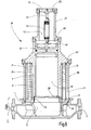
- the Fig. 8 shows a modified exemplary embodiment in which the mode of operation corresponds identically to the mode of operation of the previously described embodiment.
- the 3/2-way valve 67 at the connection point 63 of the dome 47 is therefore omitted in the drawing, as is the check valve 29 assigned to the fluid outlet 5 in the drawing.
- the control chamber 9 is arranged coaxially within the filter chamber 11.
- the latter has a circular cylinder 89 which is flanged to the connection part 1, centrally between its fluid inlet 3 and fluid outlet 5.
- the inlet 15 leading from the channel 13 into the inner filter cavity forms on the outside of its upstanding edge 90 the element receptacle for the lower end of the filter element 19, the hollow cylindrical filter material 21 of which separates the inner cavity 17 containing the unfiltrate from the filtrate space 25, which is between the outside of the filter material 21 and the cylinder 89 is located.
- this filtrate space 25 is connected to the fluid outlet 5 via a longitudinal channel 27 and an outflow opening 91 located on it.
- the cylinder 89 of the filter chamber 11 is closed at the upper end by a flange part 92 of the cylinder of the control chamber 9.
- the cylinder extends away from the flange part 92 until shortly before the upstanding edge 90 at the inlet 15, so that there is an intermediate space for the fluid connection to the space 17 forming the unfiltrate side.
- a dome 47 again forms the upper end of the control chamber 9 and the stop surface 49 as an end stop for the separating piston 43.
- the anchoring 57 for the upper end of the tension spring 59 and the connection point 63 for the valve control device 65 having the 3/2-way valve 67 are located on the closure plate 55 of the dome 47.
Landscapes
- Chemical & Material Sciences (AREA)
- Chemical Kinetics & Catalysis (AREA)
- Filtration Of Liquid (AREA)
- Fluid-Pressure Circuits (AREA)
Claims (11)
- Système de filtration de fluides, comprenant un filtre (2) primaire ayant au moins un élément de filtre pouvant être traversé dans un sens lors de l'opération de filtration et pouvant être traversé en sens contraire dans une opération de lavage en retour, comprenant un dispositif (36) de post-traitement, monté en aval du filtre (2) primaire, pour le traitement des quantités de lavage en retour cédées par celui-ci, et ayant au moins une chambre (11) de filtre, recevant les quantités de lavage en retour et ayant une entrée de fluide et une sortie de fluide et au moins un élément (19) de filtre de post-traitement, et comprenant un dispositif (9) de commande pour l'envoi par portion de la quantité de lavage en retour respective à l'élément (19) de filtre de post-traitement pouvant être associé, caractérisé en ce que le dispositif de commande à une chambre (9) de commande, ayant un premier (51) et un deuxième espace (53) pour du fluide, dont le premier (51) sert à la réception de la quantité respective de lavage en retour et le deuxième espace (53) pour du fluide peut être alimenté en un gaz comprimé ayant une pression de travail d'un gaz sous pression donnée à l'avance et en ce que le premier (51) et le deuxième espace (43) pour du fluide de la chambre (9) de commande sont séparés par un piston (43)de séparation.
- Système de filtration de fluide, suivant la revendication 1, caractérisé en ce que le gaz sous pression à la forme d'air comprimé.
- Système de filtration de fluide suivant la revendication 1 ou 2, caractérisé en ce que, pour l'envoi et l'évacuation du gaz sous pression dans ou hors du deuxième espace (53) pour du fluide de la chambre (9) de commande, sert un dispositif (65) de commande de vanne, notamment sous la forme d'une vanne (67) à 3/2 voies, pouvant être excitée électriquement, qui, en conduisant du gaz sous pression, communique avec le deuxième espace (53) pour du fluide de la chambre (9) de commande.
- Système de filtration de fluide suivant l'une des revendications précédentes, caractérisé le premier espace (51) pour du fluide de la chambre (9) de commande communique de manière permanente fluidiquement avec le côté (17 ;44) du non filtrat de l'élément (19) de filtre respectif à l'intérieur de la chambre (11) de filtre et en ce que le côté (17 ;25) du filtrat, qui est séparé du côté (17 ;44) du non filtrat par l'élément (19) de filtre respectif, a au moins de temps en temps une communication fluidique avec la sortie (5) de fluide.
- Système de filtration de fluide suivant l'une des revendications précédentes, caractérisé en ce qu'entre le côté du filtrat de l'élément (19) de filtre respectif à l'intérieur de la chambre (11) de filtre et la sortie (5) de fluide est monté, dans la liaison pour du fluide, un autre dispositif de commande de vanne, notamment sous la forme d'un clapet anti-retour (29), de préférence soumis à l'action d'un ressort.
- Système de filtration de fluide suivant l'une des revendications précédentes, caractérisé en ce que, du côté de l'entrée (3) de fluide, il y a un autre troisième dispositif (7;34) de commande de vanne, qui commande l'accès de la quantité de lavage en retour respective venant du filtre (2) primaire au dispositif (36) de post-traitement.
- Système de filtration de fluide suivant l'une des revendications précédentes, caractérisé en ce que, considéré dans le sens d'écoulement du fluide, la chambre (9) de commande de la chambre (11) du filtre est montée en amont de l'élément (19) de filtre respectif ou en ce que la chambre (11) de filtre est, avec l'élément (19) de filtre respectif, disposée concentriquement à la chambre (9) de commande et entoure celle-ci.
- Système de filtration de fluide suivant l'une des revendications précédentes, caractérisé en ce qu'un accumulateur d'énergie, de préférence sous la forme d'un ressort (59) de traction, attaque le piston (43) de séparation et en ce que l'accumulateur d'énergie traverse le deuxième espace (53) pour du fluide de la chambre (9) de commande.
- Système de filtration de fluide suivant l'une des revendications précédentes, caractérisé en ce que le dispositif (56) de post-traitement a une partie (1) de raccordement, qui peut être reliée au filtre (2) primaire, qui a l'entrée (3) de fluide pour des quantités de lavage en retour et la sortie (5) de fluide pour des quantités de lavage en retour post-traités et qui forme le support de la chambre (11) de commande et de deux chambres (11) du filtre, qui lui sont associées conjointement et qui sont disposées de part et d'autres à côté de la chambre (9) de commande, de manière à ce que, à l'intérieur de la partie (1) de raccordement, le premier espace (51) pour du fluide de la chambre (9) de commande communique en permanence avec le côté (44) du non filtrat de chacune des chambres (11) du filtre, dont les côtés (17) du filtrat à l'intérieur de la partie (1) de raccordement communiquent, au moins de temps en temps, avec la sortie (5) de fluide.
- Système de filtration de fluide suivant l'une des revendications précédentes, caractérisé en ce qu'au moins dans la partie (13) de communication fluidique, entre la chambre (9) de commande et la chambre (11) du filtre respective, est monté un chauffage (81) et/ou un dispositif (83) électronique de mesure de la pression et/ou de la température.
- Système de filtration de fluide suivant l'une des revendications précédentes, caractérisé en ce que le dispositif (36) de post-traitement est associé au filtre (2) primaire de manière à ce que la quantité de fluide, se produisant à la sortie (5) de fluide du dispositif (36) de post-traitement, puisse être retournée au côté du non filtrat du filtre (2) primaire en formant un circuit fermé.
Applications Claiming Priority (2)
| Application Number | Priority Date | Filing Date | Title |
|---|---|---|---|
| DE102015002767.0A DE102015002767A1 (de) | 2015-03-05 | 2015-03-05 | Filtervorrichtung |
| PCT/EP2016/000317 WO2016138983A1 (fr) | 2015-03-05 | 2016-02-24 | Dispositif de filtration de fluides |
Publications (2)
| Publication Number | Publication Date |
|---|---|
| EP3265202A1 EP3265202A1 (fr) | 2018-01-10 |
| EP3265202B1 true EP3265202B1 (fr) | 2021-02-17 |
Family
ID=55451153
Family Applications (1)
| Application Number | Title | Priority Date | Filing Date |
|---|---|---|---|
| EP16707388.1A Active EP3265202B1 (fr) | 2015-03-05 | 2016-02-24 | Dispositif de filtration de fluides |
Country Status (7)
| Country | Link |
|---|---|
| US (1) | US11020692B2 (fr) |
| EP (1) | EP3265202B1 (fr) |
| JP (1) | JP6820262B2 (fr) |
| KR (1) | KR102599145B1 (fr) |
| CN (1) | CN107206295B (fr) |
| DE (1) | DE102015002767A1 (fr) |
| WO (1) | WO2016138983A1 (fr) |
Cited By (2)
| Publication number | Priority date | Publication date | Assignee | Title |
|---|---|---|---|---|
| US11946439B2 (en) * | 2022-05-09 | 2024-04-02 | Caterpillar Inc. | Fuel module for engine having service valve assembly for common drain from primary and secondary filters |
| DE102023003883A1 (de) | 2023-09-25 | 2025-03-27 | Hydac Process Technology Gmbh | System |
Families Citing this family (8)
| Publication number | Priority date | Publication date | Assignee | Title |
|---|---|---|---|---|
| GB2570645A (en) | 2018-01-24 | 2019-08-07 | Maersk As | Fuel system |
| CN110420493B (zh) * | 2019-08-29 | 2021-05-04 | 中国石油化工股份有限公司 | 煤气化激冷水的过滤装置及过滤方法 |
| CN111790196B (zh) * | 2020-08-04 | 2022-05-13 | 广东建绿环保工程有限公司 | 一种高浓度难降解工业废水处理系统 |
| CN113440921B (zh) * | 2021-08-31 | 2021-11-26 | 东营联合石化有限责任公司 | 一种柴油精制用去杂装置 |
| CN114470930A (zh) * | 2022-02-18 | 2022-05-13 | 福建钰融科技有限公司 | 过滤装置及光刻胶废液再生系统 |
| DE102022204446A1 (de) | 2022-05-05 | 2023-11-09 | Hydac Process Technology Gmbh | Filtervorrichtung |
| CN117756230A (zh) * | 2024-01-05 | 2024-03-26 | 湖南亿康环保科技有限公司 | 一种基于超滤技术的工业废水回用装置 |
| CN119701477B (zh) * | 2025-02-24 | 2025-06-27 | 广东铨冠智能科技有限公司 | 一种金属碎屑多级过滤设备及过滤方法 |
Family Cites Families (15)
| Publication number | Priority date | Publication date | Assignee | Title |
|---|---|---|---|---|
| US3542197A (en) * | 1966-04-04 | 1970-11-24 | Universal Filters Inc | Fluid system with self cleaning filter |
| DD206327A1 (de) * | 1981-07-30 | 1984-01-25 | Juergen Friedrich | Rueckspuelbarer filterapparat zur filterung von viskosen medien |
| US5374351A (en) | 1993-07-27 | 1994-12-20 | D & J Filtration Systems | Filter backflushing system |
| US5462679A (en) * | 1993-09-16 | 1995-10-31 | Nelson Industries, Inc. | Apparatus and method for in situ cleaning of oil filter |
| US20030168402A1 (en) * | 2002-02-28 | 2003-09-11 | Webb Inc. | Fluid treatment system and apparatus |
| US7291267B2 (en) * | 2004-01-30 | 2007-11-06 | Ljc Technologies, L.L.C. | Molecular separator |
| DE102007054737A1 (de) * | 2007-11-16 | 2009-05-20 | Hydac Process Technology Gmbh | Filtervorrichtung |
| CN101628189B (zh) * | 2009-08-11 | 2011-02-02 | 安庆长谷川船舶科技有限公司 | 润滑油自动反冲洗组合滤器 |
| DE102010054716A1 (de) * | 2010-12-16 | 2012-06-21 | Hydac Process Technology Gmbh | Filtervorrichtung |
| DE102011100518A1 (de) * | 2011-05-05 | 2012-11-08 | Hydac Process Technology Gmbh | Filtervorrichtung |
| DE102011111457B4 (de) * | 2011-08-30 | 2022-12-15 | Hydac Process Technology Gmbh | Filtervorrichtung |
| CN202654768U (zh) * | 2012-07-18 | 2013-01-09 | 中国天辰工程有限公司 | 一种去除己二酸溶液中活性炭的系统 |
| CN203017847U (zh) * | 2013-03-20 | 2013-06-26 | 北京承天倍达过滤技术有限责任公司 | 船舶压载水处理系统用立式自动反冲洗过滤器 |
| KR101507771B1 (ko) * | 2013-05-06 | 2015-04-07 | 에이티엑스 주식회사 | 도금액 여과용 필터 하우징 |
| CN203842370U (zh) * | 2014-04-30 | 2014-09-24 | 中国石油化工集团公司 | 一种可反冲洗过滤装置 |
-
2015
- 2015-03-05 DE DE102015002767.0A patent/DE102015002767A1/de not_active Withdrawn
-
2016
- 2016-02-24 JP JP2017535881A patent/JP6820262B2/ja active Active
- 2016-02-24 CN CN201680006463.6A patent/CN107206295B/zh active Active
- 2016-02-24 EP EP16707388.1A patent/EP3265202B1/fr active Active
- 2016-02-24 WO PCT/EP2016/000317 patent/WO2016138983A1/fr not_active Ceased
- 2016-02-24 US US15/545,403 patent/US11020692B2/en active Active
- 2016-02-24 KR KR1020177024892A patent/KR102599145B1/ko active Active
Non-Patent Citations (1)
| Title |
|---|
| None * |
Cited By (3)
| Publication number | Priority date | Publication date | Assignee | Title |
|---|---|---|---|---|
| US11946439B2 (en) * | 2022-05-09 | 2024-04-02 | Caterpillar Inc. | Fuel module for engine having service valve assembly for common drain from primary and secondary filters |
| DE102023003883A1 (de) | 2023-09-25 | 2025-03-27 | Hydac Process Technology Gmbh | System |
| WO2025067723A1 (fr) | 2023-09-25 | 2025-04-03 | Hydac Process Technology Gmbh | Système de filtration de fluides |
Also Published As
| Publication number | Publication date |
|---|---|
| CN107206295B (zh) | 2020-08-25 |
| CN107206295A (zh) | 2017-09-26 |
| JP6820262B2 (ja) | 2021-01-27 |
| JP2018510759A (ja) | 2018-04-19 |
| DE102015002767A1 (de) | 2016-09-08 |
| US20180008913A1 (en) | 2018-01-11 |
| US11020692B2 (en) | 2021-06-01 |
| WO2016138983A1 (fr) | 2016-09-09 |
| EP3265202A1 (fr) | 2018-01-10 |
| KR20170128264A (ko) | 2017-11-22 |
| KR102599145B1 (ko) | 2023-11-08 |
Similar Documents
| Publication | Publication Date | Title |
|---|---|---|
| EP3265202B1 (fr) | Dispositif de filtration de fluides | |
| EP3004620B1 (fr) | Élément filtrant | |
| DE69430478T2 (de) | Filterrücksprülsystem | |
| EP2207609B1 (fr) | Dispositif de filtration | |
| DE19716085B4 (de) | Filter, insbesondere für Kraftstoffe von Verbrennungsmotoren | |
| DE68906180T2 (de) | Fluidfilter. | |
| DE3102670A1 (de) | Filteranordnung und verfahren zur filtrierung | |
| DE102011111457A1 (de) | Filtervorrichtung | |
| EP2704812A1 (fr) | Dispositif filtrant | |
| EP2393569B1 (fr) | Dispositif de filtration | |
| EP3752265B1 (fr) | Dispositif de séparation de phases | |
| DE102013020539A1 (de) | Filterelement | |
| WO2013102483A1 (fr) | Procédé et dispositif de séparation de gaz à partir d'un milieu stocké dans un réservoir | |
| EP3352877B1 (fr) | Dispositif filtrant avec pompe | |
| EP3380212B1 (fr) | Dispositif de filtration | |
| DE102006005108B4 (de) | Zylindrische Filtereinrichtung | |
| DE569467C (de) | Fluessigkeitsfilter mit Rueckspuelung | |
| DE102010018403B4 (de) | Kraftstofffilter für ein Fahrzeug | |
| DE102022124308A1 (de) | Filtriervorrichtung zum Filtrieren eines Fluids sowie betreffendes Entlüftungs- und Rückspülverfahren | |
| EP4115964B1 (fr) | Dispositif filtre | |
| EP4518993B1 (fr) | Dispositif de filtration | |
| DE1241803B (de) | Absperrvorrichtung zum automatischen, periodischen Entschlammen von Filterkerzen durch Rueckspuelung | |
| EP2374519B1 (fr) | Filtre pour liquides et méthode d'utilisation | |
| EP2987543B1 (fr) | Procede et dispositif de changement d'un filtre, en particulier d'un filtre a huile pour un moteur a combustion interne | |
| DE102006021916A1 (de) | Vorrichtung zur Entgasung und/oder Druckhaltung in einem geschlossenen Wasserkreislauf |
Legal Events
| Date | Code | Title | Description |
|---|---|---|---|
| STAA | Information on the status of an ep patent application or granted ep patent |
Free format text: STATUS: THE INTERNATIONAL PUBLICATION HAS BEEN MADE |
|
| PUAI | Public reference made under article 153(3) epc to a published international application that has entered the european phase |
Free format text: ORIGINAL CODE: 0009012 |
|
| STAA | Information on the status of an ep patent application or granted ep patent |
Free format text: STATUS: REQUEST FOR EXAMINATION WAS MADE |
|
| 17P | Request for examination filed |
Effective date: 20170726 |
|
| AK | Designated contracting states |
Kind code of ref document: A1 Designated state(s): AL AT BE BG CH CY CZ DE DK EE ES FI FR GB GR HR HU IE IS IT LI LT LU LV MC MK MT NL NO PL PT RO RS SE SI SK SM TR |
|
| AX | Request for extension of the european patent |
Extension state: BA ME |
|
| RIN1 | Information on inventor provided before grant (corrected) |
Inventor name: LINGEN, HANS-JUERGEN Inventor name: BREINIG, MARKUS Inventor name: HRIN, SEBASTIAN |
|
| DAV | Request for validation of the european patent (deleted) | ||
| DAX | Request for extension of the european patent (deleted) | ||
| STAA | Information on the status of an ep patent application or granted ep patent |
Free format text: STATUS: EXAMINATION IS IN PROGRESS |
|
| 17Q | First examination report despatched |
Effective date: 20200423 |
|
| GRAP | Despatch of communication of intention to grant a patent |
Free format text: ORIGINAL CODE: EPIDOSNIGR1 |
|
| STAA | Information on the status of an ep patent application or granted ep patent |
Free format text: STATUS: GRANT OF PATENT IS INTENDED |
|
| INTG | Intention to grant announced |
Effective date: 20201127 |
|
| GRAS | Grant fee paid |
Free format text: ORIGINAL CODE: EPIDOSNIGR3 |
|
| GRAA | (expected) grant |
Free format text: ORIGINAL CODE: 0009210 |
|
| STAA | Information on the status of an ep patent application or granted ep patent |
Free format text: STATUS: THE PATENT HAS BEEN GRANTED |
|
| AK | Designated contracting states |
Kind code of ref document: B1 Designated state(s): AL AT BE BG CH CY CZ DE DK EE ES FI FR GB GR HR HU IE IS IT LI LT LU LV MC MK MT NL NO PL PT RO RS SE SI SK SM TR |
|
| REG | Reference to a national code |
Ref country code: GB Ref legal event code: FG4D Free format text: NOT ENGLISH |
|
| REG | Reference to a national code |
Ref country code: CH Ref legal event code: EP |
|
| REG | Reference to a national code |
Ref country code: DE Ref legal event code: R096 Ref document number: 502016012366 Country of ref document: DE |
|
| REG | Reference to a national code |
Ref country code: AT Ref legal event code: REF Ref document number: 1360719 Country of ref document: AT Kind code of ref document: T Effective date: 20210315 |
|
| REG | Reference to a national code |
Ref country code: IE Ref legal event code: FG4D Free format text: LANGUAGE OF EP DOCUMENT: GERMAN |
|
| REG | Reference to a national code |
Ref country code: SE Ref legal event code: TRGR |
|
| REG | Reference to a national code |
Ref country code: LT Ref legal event code: MG9D |
|
| REG | Reference to a national code |
Ref country code: NL Ref legal event code: MP Effective date: 20210217 |
|
| PG25 | Lapsed in a contracting state [announced via postgrant information from national office to epo] |
Ref country code: GR Free format text: LAPSE BECAUSE OF FAILURE TO SUBMIT A TRANSLATION OF THE DESCRIPTION OR TO PAY THE FEE WITHIN THE PRESCRIBED TIME-LIMIT Effective date: 20210518 Ref country code: FI Free format text: LAPSE BECAUSE OF FAILURE TO SUBMIT A TRANSLATION OF THE DESCRIPTION OR TO PAY THE FEE WITHIN THE PRESCRIBED TIME-LIMIT Effective date: 20210217 Ref country code: HR Free format text: LAPSE BECAUSE OF FAILURE TO SUBMIT A TRANSLATION OF THE DESCRIPTION OR TO PAY THE FEE WITHIN THE PRESCRIBED TIME-LIMIT Effective date: 20210217 Ref country code: NO Free format text: LAPSE BECAUSE OF FAILURE TO SUBMIT A TRANSLATION OF THE DESCRIPTION OR TO PAY THE FEE WITHIN THE PRESCRIBED TIME-LIMIT Effective date: 20210517 Ref country code: PT Free format text: LAPSE BECAUSE OF FAILURE TO SUBMIT A TRANSLATION OF THE DESCRIPTION OR TO PAY THE FEE WITHIN THE PRESCRIBED TIME-LIMIT Effective date: 20210617 Ref country code: BG Free format text: LAPSE BECAUSE OF FAILURE TO SUBMIT A TRANSLATION OF THE DESCRIPTION OR TO PAY THE FEE WITHIN THE PRESCRIBED TIME-LIMIT Effective date: 20210517 Ref country code: LT Free format text: LAPSE BECAUSE OF FAILURE TO SUBMIT A TRANSLATION OF THE DESCRIPTION OR TO PAY THE FEE WITHIN THE PRESCRIBED TIME-LIMIT Effective date: 20210217 |
|
| PG25 | Lapsed in a contracting state [announced via postgrant information from national office to epo] |
Ref country code: LV Free format text: LAPSE BECAUSE OF FAILURE TO SUBMIT A TRANSLATION OF THE DESCRIPTION OR TO PAY THE FEE WITHIN THE PRESCRIBED TIME-LIMIT Effective date: 20210217 Ref country code: PL Free format text: LAPSE BECAUSE OF FAILURE TO SUBMIT A TRANSLATION OF THE DESCRIPTION OR TO PAY THE FEE WITHIN THE PRESCRIBED TIME-LIMIT Effective date: 20210217 Ref country code: RS Free format text: LAPSE BECAUSE OF FAILURE TO SUBMIT A TRANSLATION OF THE DESCRIPTION OR TO PAY THE FEE WITHIN THE PRESCRIBED TIME-LIMIT Effective date: 20210217 Ref country code: NL Free format text: LAPSE BECAUSE OF FAILURE TO SUBMIT A TRANSLATION OF THE DESCRIPTION OR TO PAY THE FEE WITHIN THE PRESCRIBED TIME-LIMIT Effective date: 20210217 |
|
| PG25 | Lapsed in a contracting state [announced via postgrant information from national office to epo] |
Ref country code: IS Free format text: LAPSE BECAUSE OF FAILURE TO SUBMIT A TRANSLATION OF THE DESCRIPTION OR TO PAY THE FEE WITHIN THE PRESCRIBED TIME-LIMIT Effective date: 20210617 |
|
| REG | Reference to a national code |
Ref country code: BE Ref legal event code: MM Effective date: 20210228 |
|
| PG25 | Lapsed in a contracting state [announced via postgrant information from national office to epo] |
Ref country code: CH Free format text: LAPSE BECAUSE OF NON-PAYMENT OF DUE FEES Effective date: 20210228 Ref country code: SM Free format text: LAPSE BECAUSE OF FAILURE TO SUBMIT A TRANSLATION OF THE DESCRIPTION OR TO PAY THE FEE WITHIN THE PRESCRIBED TIME-LIMIT Effective date: 20210217 Ref country code: LU Free format text: LAPSE BECAUSE OF NON-PAYMENT OF DUE FEES Effective date: 20210224 Ref country code: LI Free format text: LAPSE BECAUSE OF NON-PAYMENT OF DUE FEES Effective date: 20210228 Ref country code: CZ Free format text: LAPSE BECAUSE OF FAILURE TO SUBMIT A TRANSLATION OF THE DESCRIPTION OR TO PAY THE FEE WITHIN THE PRESCRIBED TIME-LIMIT Effective date: 20210217 Ref country code: EE Free format text: LAPSE BECAUSE OF FAILURE TO SUBMIT A TRANSLATION OF THE DESCRIPTION OR TO PAY THE FEE WITHIN THE PRESCRIBED TIME-LIMIT Effective date: 20210217 |
|
| REG | Reference to a national code |
Ref country code: DE Ref legal event code: R097 Ref document number: 502016012366 Country of ref document: DE |
|
| PG25 | Lapsed in a contracting state [announced via postgrant information from national office to epo] |
Ref country code: SK Free format text: LAPSE BECAUSE OF FAILURE TO SUBMIT A TRANSLATION OF THE DESCRIPTION OR TO PAY THE FEE WITHIN THE PRESCRIBED TIME-LIMIT Effective date: 20210217 Ref country code: RO Free format text: LAPSE BECAUSE OF FAILURE TO SUBMIT A TRANSLATION OF THE DESCRIPTION OR TO PAY THE FEE WITHIN THE PRESCRIBED TIME-LIMIT Effective date: 20210217 Ref country code: MC Free format text: LAPSE BECAUSE OF FAILURE TO SUBMIT A TRANSLATION OF THE DESCRIPTION OR TO PAY THE FEE WITHIN THE PRESCRIBED TIME-LIMIT Effective date: 20210217 Ref country code: DK Free format text: LAPSE BECAUSE OF FAILURE TO SUBMIT A TRANSLATION OF THE DESCRIPTION OR TO PAY THE FEE WITHIN THE PRESCRIBED TIME-LIMIT Effective date: 20210217 |
|
| PLBE | No opposition filed within time limit |
Free format text: ORIGINAL CODE: 0009261 |
|
| STAA | Information on the status of an ep patent application or granted ep patent |
Free format text: STATUS: NO OPPOSITION FILED WITHIN TIME LIMIT |
|
| 26N | No opposition filed |
Effective date: 20211118 |
|
| GBPC | Gb: european patent ceased through non-payment of renewal fee |
Effective date: 20210517 |
|
| PG25 | Lapsed in a contracting state [announced via postgrant information from national office to epo] |
Ref country code: AL Free format text: LAPSE BECAUSE OF FAILURE TO SUBMIT A TRANSLATION OF THE DESCRIPTION OR TO PAY THE FEE WITHIN THE PRESCRIBED TIME-LIMIT Effective date: 20210217 Ref country code: ES Free format text: LAPSE BECAUSE OF FAILURE TO SUBMIT A TRANSLATION OF THE DESCRIPTION OR TO PAY THE FEE WITHIN THE PRESCRIBED TIME-LIMIT Effective date: 20210217 Ref country code: IE Free format text: LAPSE BECAUSE OF NON-PAYMENT OF DUE FEES Effective date: 20210224 Ref country code: FR Free format text: LAPSE BECAUSE OF NON-PAYMENT OF DUE FEES Effective date: 20210417 |
|
| PG25 | Lapsed in a contracting state [announced via postgrant information from national office to epo] |
Ref country code: SI Free format text: LAPSE BECAUSE OF FAILURE TO SUBMIT A TRANSLATION OF THE DESCRIPTION OR TO PAY THE FEE WITHIN THE PRESCRIBED TIME-LIMIT Effective date: 20210217 |
|
| REG | Reference to a national code |
Ref country code: AT Ref legal event code: MM01 Ref document number: 1360719 Country of ref document: AT Kind code of ref document: T Effective date: 20210224 |
|
| PG25 | Lapsed in a contracting state [announced via postgrant information from national office to epo] |
Ref country code: GB Free format text: LAPSE BECAUSE OF NON-PAYMENT OF DUE FEES Effective date: 20210517 Ref country code: AT Free format text: LAPSE BECAUSE OF NON-PAYMENT OF DUE FEES Effective date: 20210224 |
|
| PG25 | Lapsed in a contracting state [announced via postgrant information from national office to epo] |
Ref country code: IS Free format text: LAPSE BECAUSE OF FAILURE TO SUBMIT A TRANSLATION OF THE DESCRIPTION OR TO PAY THE FEE WITHIN THE PRESCRIBED TIME-LIMIT Effective date: 20210617 |
|
| PG25 | Lapsed in a contracting state [announced via postgrant information from national office to epo] |
Ref country code: BE Free format text: LAPSE BECAUSE OF NON-PAYMENT OF DUE FEES Effective date: 20210228 |
|
| PG25 | Lapsed in a contracting state [announced via postgrant information from national office to epo] |
Ref country code: CY Free format text: LAPSE BECAUSE OF FAILURE TO SUBMIT A TRANSLATION OF THE DESCRIPTION OR TO PAY THE FEE WITHIN THE PRESCRIBED TIME-LIMIT Effective date: 20210217 |
|
| PG25 | Lapsed in a contracting state [announced via postgrant information from national office to epo] |
Ref country code: HU Free format text: LAPSE BECAUSE OF FAILURE TO SUBMIT A TRANSLATION OF THE DESCRIPTION OR TO PAY THE FEE WITHIN THE PRESCRIBED TIME-LIMIT; INVALID AB INITIO Effective date: 20160224 |
|
| PG25 | Lapsed in a contracting state [announced via postgrant information from national office to epo] |
Ref country code: MK Free format text: LAPSE BECAUSE OF FAILURE TO SUBMIT A TRANSLATION OF THE DESCRIPTION OR TO PAY THE FEE WITHIN THE PRESCRIBED TIME-LIMIT Effective date: 20210217 |
|
| PG25 | Lapsed in a contracting state [announced via postgrant information from national office to epo] |
Ref country code: MT Free format text: LAPSE BECAUSE OF FAILURE TO SUBMIT A TRANSLATION OF THE DESCRIPTION OR TO PAY THE FEE WITHIN THE PRESCRIBED TIME-LIMIT Effective date: 20210217 |
|
| PGFP | Annual fee paid to national office [announced via postgrant information from national office to epo] |
Ref country code: IT Payment date: 20250207 Year of fee payment: 10 |
|
| PG25 | Lapsed in a contracting state [announced via postgrant information from national office to epo] |
Ref country code: TR Free format text: LAPSE BECAUSE OF FAILURE TO SUBMIT A TRANSLATION OF THE DESCRIPTION OR TO PAY THE FEE WITHIN THE PRESCRIBED TIME-LIMIT Effective date: 20210217 |
|
| PGFP | Annual fee paid to national office [announced via postgrant information from national office to epo] |
Ref country code: SE Payment date: 20251215 Year of fee payment: 11 |
|
| PGFP | Annual fee paid to national office [announced via postgrant information from national office to epo] |
Ref country code: DE Payment date: 20260228 Year of fee payment: 11 |