EP3265247B1 - Rotordüse für ein hochdruckreinigungsgerät - Google Patents
Rotordüse für ein hochdruckreinigungsgerät Download PDFInfo
- Publication number
- EP3265247B1 EP3265247B1 EP15708480.7A EP15708480A EP3265247B1 EP 3265247 B1 EP3265247 B1 EP 3265247B1 EP 15708480 A EP15708480 A EP 15708480A EP 3265247 B1 EP3265247 B1 EP 3265247B1
- Authority
- EP
- European Patent Office
- Prior art keywords
- housing
- accordance
- rotor nozzle
- nozzle
- liquid
- Prior art date
- Legal status (The legal status is an assumption and is not a legal conclusion. Google has not performed a legal analysis and makes no representation as to the accuracy of the status listed.)
- Active
Links
Images


Classifications
-
- B—PERFORMING OPERATIONS; TRANSPORTING
- B05—SPRAYING OR ATOMISING IN GENERAL; APPLYING FLUENT MATERIALS TO SURFACES, IN GENERAL
- B05B—SPRAYING APPARATUS; ATOMISING APPARATUS; NOZZLES
- B05B3/00—Spraying or sprinkling apparatus with moving outlet elements or moving deflecting elements
- B05B3/02—Spraying or sprinkling apparatus with moving outlet elements or moving deflecting elements with rotating elements
- B05B3/04—Spraying or sprinkling apparatus with moving outlet elements or moving deflecting elements with rotating elements driven by the liquid or other fluent material discharged, e.g. the liquid actuating a motor before passing to the outlet
- B05B3/0417—Spraying or sprinkling apparatus with moving outlet elements or moving deflecting elements with rotating elements driven by the liquid or other fluent material discharged, e.g. the liquid actuating a motor before passing to the outlet comprising a liquid driven rotor, e.g. a turbine
- B05B3/0429—Spraying or sprinkling apparatus with moving outlet elements or moving deflecting elements with rotating elements driven by the liquid or other fluent material discharged, e.g. the liquid actuating a motor before passing to the outlet comprising a liquid driven rotor, e.g. a turbine the rotating outlet elements being directly attached to the rotor or being an integral part thereof
- B05B3/043—Rotor nozzles
-
- B—PERFORMING OPERATIONS; TRANSPORTING
- B08—CLEANING
- B08B—CLEANING IN GENERAL; PREVENTION OF FOULING IN GENERAL
- B08B3/00—Cleaning by methods involving the use or presence of liquid or steam
- B08B3/02—Cleaning by the force of jets or sprays
- B08B3/026—Cleaning by making use of hand-held spray guns; Fluid preparations therefor
Definitions
- the invention relates to a rotor nozzle for a high-pressure cleaning device having the features of the preamble of claim 1.
- a compact liquid jet revolving on a conical surface can be produced, which can be directed, for example, onto a surface to be cleaned.
- the inlet of the housing may be supplied by a high pressure cleaning device pressurized liquid, preferably water.
- a nozzle body which is mounted only on one side of the pan-shaped recess and can move in the housing about its longitudinal axis, moreover.
- the nozzle body has a passageway through which the liquid can pass through the perforated recess of the housing.
- the longitudinal axis of the nozzle body is inclined relative to the longitudinal axis of the housing.
- the nozzle body By virtue of the liquid entering tangentially into the housing, the nozzle body is pressed into the socket-shaped depression, which forms a bearing for the nozzle body, and at the same time the nozzle body is set in rotation about the housing longitudinal axis.
- the exiting liquid jet also describes the desired circular movement, so that when a comparable pressure with dot jet nozzles a relatively large area can be acted upon with liquid.
- the nozzle body has a very high rotational speed about the longitudinal axis of the housing, this can, however, result in the liquid jet emerging from the outlet fanning out and thereby reducing the cleaning effect of the liquid jet occurring on the surface to be cleaned.
- the nozzle body In addition to its orbital movement about the longitudinal axis of the housing, the nozzle body performs a self-rotation about its own longitudinal axis. This self-rotation can also fanning out of the outlet Liquid jet and thus lead to a reduction of the cleaning effect.
- Object of the present invention is to provide a rotor nozzle of the type mentioned in such a way that it is less sensitive to pressure fluctuations of the liquid and has a longer life.
- the insert according to the invention forms flow resistance elements which slow down the circulation movement of the liquid within the housing in the region of the flow resistance elements.
- the insert is arranged downstream of the support surface on which the nozzle body is supported with a contact surface on its circumference.
- the support surface may be configured, for example, circular cylindrical or conical, wherein it has no profiling. In the region of the support surface thus an unhindered circulation movement of the liquid is ensured.
- This has the advantage that the insert element arranged downstream of the support surface and having flow resistance elements does not impair the so-called "startup behavior" of the nozzle body.
- the startup behavior is understood to mean the start of the rotation of the nozzle body about the longitudinal axis of the housing.
- the nozzle body Before the housing is supplied under pressure liquid, the nozzle body is relative to the housing at rest, so he does not perform any rotational movement about the housing longitudinal axis. If the liquid supplied to the interior of the housing via the at least one tangential inlet fluid under pressure, so the nozzle body is reliably rotated, but the speed of the nozzle body should not exceed a maximum speed as far as possible to fanning the emerging from the outlet Liquid jet to avoid. This is ensured by the positioning of the insert downstream of the support surface.
- the provision of the insert part has the additional advantage that the housing must have no profiling on the inside.
- An internal profiling could affect the mechanical stability of the housing.
- the housing may have on its inside a relatively smooth surface, so that there is virtually no risk that form cracks in the housing when it is acted upon by the relatively high pressure of the liquid.
- the housing can be a relatively small material thickness have and yet is characterized by a very high mechanical strength, and the provision of the housing rotatably and axially immovably connectable insert allows positioning in the housing flow resistance elements, by the speed of the nozzle body can be limited by the flow resistance elements slowing down the movement of the liquid act.
- the flow resistance elements of the insert act slowing down on the circulating liquid.
- the rotational speed of the nozzle body can be influenced only indirectly, because the flow resistance elements do not directly exert a frictional force on the nozzle body. It is therefore desirable to design the flow resistance elements such that they act particularly strongly on the liquid.
- the flow resistance elements for impact of liquid in each case projecting into the housing baffle and the baffle is upstream of the liquid a guide surface, wherein the guide surface is oriented obliquely to a radial plane of the housing relative to the longitudinal axis thereof.
- On the baffles may bounce liquid, which is thereby hindered in their movement, and the baffles ensure that the liquid is supplied to the immediately following baffle.
- a significant slowdown of the liquid flow can be achieved.
- the insert has a constant wall thickness along its circumference, at least in the area of the flow resistance elements. This facilitates the shaping of the insert part in an injection molding process.
- the insert part has in such a configuration on its outer side a contour which corresponds to the contour on the inside of the insert part.
- the insert part can be screwed to the housing and has a stop surface, which can be applied in the end position of the insert part to an inner shoulder of the housing.
- the insert can be screwed so far into the housing in such an embodiment of the invention until it rests with its stop surface on an inner shoulder of the housing.
- the insert part comprises an external thread which cooperates with a first internal thread of the housing.
- the external thread of the insert is conveniently located downstream of the flow resistance elements.
- the housing has, upstream of the cup-shaped depression, a complementary internal thread to the external thread of the insert part.
- the screwing of the insert is identical to the flow direction of the liquid within the housing.
- the circulating liquid in the housing about its longitudinal axis exerts a force in the circumferential direction on the flow resistance elements of the insert part. Under the action of this force, the insert is pressed with a stop surface against the inner shoulder of the housing, since the screwing of the insert, that is, the directions of rotation of the external thread of the insert and the first internal thread of the housing with the flow direction of the liquid match.
- the circulating liquid thus ensures a structurally simple manner that the screw connection between the insert and the housing does not accidentally dissolve, but the insert is pressed by the liquid in its end position.
- the first internal thread of the housing is designed to be more continuous.
- the insert part for producing a stable screw connection has to be twisted only slightly relative to the housing.
- the insert part must be rotated by a maximum of 360 ° relative to the housing in order to produce a stable screw connection.
- the insert part has to perform less than one revolution in order to reach an end position.
- the inlet of the housing is supplied with pressurized liquid during use of the rotor nozzle.
- the rotor nozzle can have a connection part which can be connected to the housing for connection to a liquid supply line.
- a connection part for example, a jet pipe can be used, which can be connected to the free end of a pressure hose is, over which the jet pipe can be supplied by a high pressure cleaning device with pressurized liquid.
- connection part is rotatably connected to the housing.
- the connecting part is conveniently screwed to the housing of the rotor nozzle.
- the connection part has an external thread which can be screwed into a second internal thread of the housing.
- direction of rotation of the second internal thread coincides with the direction of rotation of the first internal thread.
- a matching direction of rotation of the two internal threads facilitates the shaping of the housing and allows a particularly cost-effective production.
- the direction of rotation of the second internal thread is opposite to the direction of rotation of the first internal thread.
- the screwing-in direction of the insert part corresponds to the circulating movement of the liquid within the housing.
- the insert is thereby pressed by the liquid in its end position.
- the reaction force of the housing does not lead to a loosening of the screw connection between the housing and the connecting part
- the direction of rotation of the second internal thread is favorably opposite to the direction of rotation of the first internal thread.
- the baffles are at least partially disposed in a radial plane relative to the longitudinal axis of the housing.
- the circulating around the housing longitudinal axis liquid can thereby impinge perpendicular to the baffle at least in a region of the baffle and thereby experience a particularly strong deceleration.
- baffle surface connects continuously to each baffle, that is, the baffle closes seamlessly to the baffle and the baffle follows steadily the baffle.
- the surface normals of the guide and baffles merge into one another continuously.
- the guide surfaces are bent in an advantageous embodiment, at least in regions arcuately.
- the guide surfaces are convexly curved at least in regions outwards, that is, in the direction away from the longitudinal axis of the housing.
- Each guide surface in combination with the baffle surface adjoining the guide surface, advantageously forms a channel-shaped widening of the interior of the housing.
- the trough-shaped extensions extend in the direction of the outlet of the housing.
- channel-shaped extensions are aligned obliquely to the longitudinal axis of the housing.
- the channel-shaped extensions are expediently designed to be open.
- the channel-shaped extensions are closed in an advantageous embodiment of the invention. They may be limited, for example, by an end wall, which forms on the outside a stop surface of the insert part, which can be applied in the end position of the insert part to an inner shoulder of the housing.
- the insert part is given a particularly high mechanical load-bearing capacity and at the same time it is ensured that the insert part is pressed against the inner shoulder of the housing by the pressurized liquid.
- a plurality of guide and baffles in the flow direction of the liquid are arranged alternately one behind the other. In the direction of flow of the liquid thus adjoins each baffle an impact surface and at each baffle is in turn followed by a guide surface.
- each guide surface in combination with the baffle surface adjoining the guide surface forms an S-shaped or sawtooth-shaped contour in a plane aligned perpendicular to the longitudinal axis of the housing. It has been shown that a particularly effective slowdown of the liquid flow can be achieved.
- the guide surface extends in the circumferential direction of the housing conveniently over a larger area than the immediately following impact surface.
- the guide surface extends in the circumferential direction over an area that is at least twice as large as the impact surface following the guide surface.
- the liquid is thereby guided over a relatively large peripheral area in each case on a baffle and then braked at this.
- both the housing and the insert are made in the form of an injection molded part from a plastic material.
- the insert forms a prefabricated unit, which can be easily inserted into the housing and bolted to it.
- the assembly of the rotor nozzle is therefore very simple.
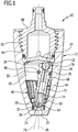
- FIG. 10 an advantageous embodiment of a rotor nozzle according to the invention is shown schematically, which is generally occupied by the reference numeral 10.
- the rotor nozzle 10 has a housing 12 with a housing bottom 14 and a housing cover 16.
- the housing bottom 14 is embodied like a disk and has a plurality of tangential inlets 18. which open into an interior 20 of the housing 12.
- the interior 20 is surrounded by the housing cover 16 and tapers from the tangential inlets 18 to an outlet 22, which is arranged on an end wall 24 of the housing cover 16.
- pressurized liquid can be supplied to the interior 20, which can rotate in the interior 20 about a housing longitudinal axis 26 and emerge from the housing 12 via the outlet 22.
- a bearing is arranged in the interior 20 in the form of a bearing ring 28 which forms a pan-shaped recess 30.
- the bearing ring 28 carries on its outer side a sealing ring 32 and is thereby sealed from the housing cover 16.
- the housing cover 16 Upstream of the bearing ring 28, the housing cover 16 has a first internal thread 34, which is designed to be more continuous. In the illustrated embodiment, the first internal thread 34 is formed slaughter warmth. Upstream of the first internal thread 34 of the housing cover 16 forms an inner shoulder 36 and upstream of the inner shoulder 36, the housing cover 16 in the form of a conical bearing portion 38 is configured. Upstream of the conical bearing region 38, the housing cover 16 forms a smooth support surface 40, which is conical in the illustrated embodiment. Facing away from the outlet 22, the housing cover 16 at a distance from the support surface 40, a second inner shoulder 42 on which the housing bottom 14 abuts.
- the direction of rotation of the second internal thread 44 may be opposite to the direction of rotation of the first internal thread 34.
- an insert member 46 is screwed, which in the FIGS. 3 and 4 is shown schematically.
- the insert part 46 has an external thread 48, which can be screwed to the first internal thread 34 of the housing cover 16. Upstream of the external thread 48, the insert member 46 forms a plurality of circumferentially uniformly distributed flow resistance elements 50, each having a baffle 52, which is preceded by a guide surface 54.
- the baffles and guide surfaces 52, 54 are arranged in the circumferential direction of the insert part 46 in alternation behind one another and continuously merge into one another.
- baffle and guide surfaces in the illustrated embodiment form an S-shaped contour by both the baffles 52 and the guide surfaces 54 are curved arcuately.
- the baffles 52 have an end portion 56 oriented in a radial plane with respect to the housing longitudinal axis 26. This is going out FIG. 4 clear.
- the extensions are open at their upper end facing the inlets 18 and at their lower end facing the outlet 22 the extensions 55 are closed by an end wall 57.
- the insert part 46 In the area of the flow resistance elements 50, the insert part 46 has a constant material thickness. This facilitates the manufacture of the insert 46 in an injection molding process.
- the insert 46 extends from the first internal thread 34 of the housing cover 16 to an upstream edge 58 of the conical abutment portion 38, so that the circular cylindrical support surface 40 is not affected by the insert 46.
- the insert 46 In the transition region between the external thread 48 and the flow resistance elements 50 forms the insert 46 with the outside of the End wall 57 from a stop surface 60, and the insert member 46 can be screwed with its external thread 48 so far into the first internal thread 34 until the stop surface 60 rests against the first inner shoulder 36 of the housing cover 16.
- a nozzle body 62 can be inserted into the interior 20, which is supported with a crowned end 64 in the cup-shaped recess 30 of the bearing ring 28.
- the nozzle body 62 has a nozzle 66, which forms the crowned end 64, and a nozzle carrier 68, which has a passage 72 extending in the axial direction along a longitudinal axis 70 of the nozzle body 62. In the passage 72, the nozzle 66 is pressed.
- the nozzle 66 has a nozzle channel 74 aligned flush with the passageway 72. In its end region facing away from the nozzle 66, the through-passage 72 widens in stages.
- a centrifugal force-enhancing mass body in the form of a steel ball 76 is held in the area of the nozzle 66.
- the steel ball 76 is followed in the passage 72 in the direction of the nozzle 66, a rectifier 78, which has two mutually perpendicular, parallel to the longitudinal axis 70 of the nozzle body 62 extending and the passageway 72 diametrically interspersed walls.
- the steel ball 76 can be flowed around in the passageway 72 of liquid, so that, after passing through the rectifier 78 and the nozzle 66, it can flow through the bearing ring 28 and the outlet 22 and thereby leave the rotor nozzle 10.
- the nozzle carrier 68 has a circumferentially circumferential annular groove in which an O-ring 86 is held against rotation. Relative to the longitudinal axis 70 of the nozzle body 62, the O-ring 86 protrudes in the radial direction beyond the nozzle carrier 68. It forms a contact surface, with which the nozzle body 62 can be applied to the support surface 40 of the housing cover 16. This is going out FIG. 1 clear.
- the nozzle body 62 extends over at least one third of its total length in the region upstream of the insert part, that is to say in the region between the insert part 46 and the housing bottom 14.
- the channel-shaped extensions 55 are aligned parallel to the longitudinal axis 70 of the nozzle body 62.
- connection part 88 The housing 12 of the rotor nozzle 10 is screwed to a connection part 88, via which the housing 12 of a high-pressure cleaning device under pressure liquid can be supplied.
- connection part 88 has an external thread 90 which can be screwed into the second internal thread 44 of the housing cover 16.
- Liquid supplied via the connection part 88 to the housing 12 passes via the tangential inlets 18 into the interior 20 of the housing 12 and can leave the interior 20 via the through-channel 72, the nozzle channel 74, the bearing ring 28 and the outlet 22.
- the interior space 20 is filled with liquid during operation of the rotor nozzle 10, which is rotated about the housing longitudinal axis 26 by the liquid flowing in via the tangential inlets 18. It thus forms in the interior 20 a rotating about the housing longitudinal axis 26 liquid column.
- the rotating liquid column takes with its spherical front end 64 on the bearing ring 28 supporting the nozzle body 62, so that it also rotates about the housing longitudinal axis 26.
- the nozzle body 62 rests against the circular-cylindrical support surface 40 via the O-ring 86 held non-rotatably on the nozzle body 62.
- the longitudinal axis 70 of the nozzle body 62 is thus inclined to the housing longitudinal axis 26.
- the liquid circulating about the housing longitudinal axis 26 experiences a deceleration due to the baffles 52, on which a part of the circulating liquid impinges. Liquid is in each case supplied via the guide surfaces 54 to a baffle surface 52, so that an effective Deceleration of the liquid can be achieved. Upstream of the insert 46, however, the liquid undergoes no deceleration. This ensures that the nozzle body 62 is reliably offset from the liquid in rotation about the housing longitudinal axis 26. In this area, the nozzle body 62 is located only on one side of the housing longitudinal axis 26, whereas the nozzle body 62 in the region of the insert part 46 and the nozzle 66, the housing longitudinal axis 26 intersects.
- the liquid flowing around the nozzle body 62 could drive the nozzle body 62 in the region in which it intersects the longitudinal axis of the housing 26 to self-rotate about the longitudinal axis 70 of the nozzle body 62.
- the self-rotation of the nozzle body 62 can be kept low.
- the provision of the flow resistance elements 50 achieves a limitation of the rotational speed that the nozzle body 62 has during its rotational movement about the housing longitudinal axis 26.
- the reduction of the self-rotation of the nozzle body 62 and the reduction of the rotational speed of the nozzle body 62 about the housing longitudinal axis 26 ensure that the liquid jet emerging from the housing 12 fans out only slightly.
- the rotor nozzle 10 is therefore characterized by a particularly large cleaning effect.
- the provision of the insert 46 in the form of a prefabricated unit, which can be inserted into the housing cover 16 and screwed with this, has the advantage that the housing cover 16 has a high mechanical strength, since its inner wall both in the conical contact area 38 and in the arranged upstream of the abutment portion 38 may have a smooth surface structure.
- the material thickness of the housing cover 16 can be kept relatively low.
Landscapes
- Nozzles (AREA)
Description
- Die Erfindung betrifft eine Rotordüse für ein Hochdruckreinigungsgerät mit den Merkmalen des Oberbegriffes von Patentanspruch 1.
- Mit Hilfe einer derartigen Rotordüse kann ein auf einem Kegelmantel umlaufender kompakter Flüssigkeitsstrahl erzeugt werden, der beispielsweise auf eine zu reinigende Fläche gerichtet werden kann. Dem Einlass des Gehäuses kann von einem Hochdruckreinigungsgerät unter Druck stehende Flüssigkeit, vorzugsweise Wasser, zugeführt werden. In dem Gehäuse befindet sich ein Düsenkörper, der nur einseitig an der pfannenförmigen Vertiefung gelagert ist und sich im Übrigen im Gehäuse um dessen Längsachse bewegen kann. Der Düsenkörper weist einen Durchgangskanal auf, durch den die Flüssigkeit die durchbrochene Vertiefung des Gehäuses passieren kann. Die Längsachse des Düsenkörpers ist gegenüber der Längsachse des Gehäuses geneigt. Durch die tangential in das Gehäuse eintretende Flüssigkeit wird der Düsenkörper in die pfannenförmige Vertiefung gedrückt, die ein Lager für den Düsenkörper ausbildet, und gleichzeitig wird der Düsenkörper in Rotation um die Gehäuselängsachse versetzt. Dies hat zur Folge, dass der austretende Flüssigkeitsstrahl ebenfalls die gewünschte kreisförmige Bewegung beschreibt, so dass bei einem mit Punktstrahldüsen vergleichbaren Druck eine verhältnismäßig große Fläche mit Flüssigkeit beaufschlagt werden kann.
- Weist der Düsenkörper eine sehr hohe Drehzahl um die Längsachse des Gehäuses auf, so kann dies allerdings zur Folge haben, dass sich der aus dem Auslass heraustretende Flüssigkeitsstrahl auffächert und sich dadurch die Reinigungswirkung des auf die zu reinigende Fläche auftretenden Flüssigkeitsstrahls verringert wird.
- Zusätzlich zu seiner Umlaufbewegung um die Längsachse des Gehäuses führt der Düsenkörper eine Eigenrotation um seine eigene Längsachse aus. Auch diese Eigenrotation kann zu einem Auffächern des aus dem Auslass heraustretenden Flüssigkeitsstrahls und damit zu einer Verminderung der Reinigungswirkung führen.
- Aus der
DE 38 36 053 C1 ist eine Rotordüse mit den Merkmalen des Oberbegriffes von Patentanspruch 1 bekannt. - Um die Drehzahl des Düsenkörpers einzuschränken, wird in der
DE 44 19 404 A1 vorgeschlagen, in das Gehäuse ein Einsatzteil einzusetzen, das an der Wand des Gehäuses anliegt und das an seinem dem Auslass abgewandten Endbereich eine Vielzahl schlitzförmiger Ausnehmungen aufweist, die zwischen sich Lamellen bilden. Durch die in Umfangsrichtung im Abstand zueinander angeordneten Lamellen wird die Strömung der Flüssigkeit innerhalb des Gehäuses verlangsamt und dies wiederum hat zur Folge, dass die Drehzahl des Düsenkörpers reduziert wird. Die um die Gehäuselängsachse umlaufende Flüssigkeit übt auf die Lamellen eine Kraft in Umfangsrichtung aus. Dies kann zur Folge haben, dass das Einsatzteil innerhalb des Gehäuses um dessen Längsachse rotiert, und dies wiederum kann zu einer Beeinträchtigung sowohl des Einsatzteiles als auch des Gehäuses führen. Mögliche Druckschwankungen der Flüssigkeit können darüber hinaus zur Folge haben, dass das Einsatzteil in axialer Richtung relativ zum Gehäuse bewegt wird. Auch eine derartige Relativbewegung kann zu einer Beschädigung des Einsatzteiles und des Gehäuses führen, so dass die Lebensdauer der Rotordüse beeinträchtigt wird. - Aufgabe der vorliegenden Erfindung ist es, eine Rotordüse der eingangs genannten Art derart auszugestalten, dass sie unempfindlicher ist gegenüber Druckschwankungen der Flüssigkeit und eine längere Lebensdauer aufweist.
- Diese Aufgabe wird durch eine Rotordüse mit den Merkmalen von Patentanspruch 1 gelöst.
- Durch die Bereitstellung einer drehfesten und axial unbeweglichen Verbindung zwischen dem Einsatzteil und dem Gehäuse kann einer unbeabsichtigten Bewegung des Einsatzteils relativ zum Gehäuse entgegengewirkt werden. Wie voranstehend erläutert, besteht die Gefahr einer unbeabsichtigten Relativbewegung vor allem dann, wenn die Flüssigkeit Druckschwankungen unterliegt.
- Das erfindungsgemäße Einsatzteil bildet Strömungswiderstandselemente aus, die die Umlaufbewegung der Flüssigkeit innerhalb des Gehäuses im Bereich der Strömungswiderstandselemente verlangsamen. Das Einsatzteil ist stromabwärts der Stützfläche angeordnet, an der sich der Düsenkörper mit einer Anlagefläche an seinem Umfang abstützt. Die Stützfläche kann beispielsweise kreiszylindrisch oder konisch ausgestaltet sein, wobei sie keinerlei Profilierung aufweist. Im Bereich der Stützfläche ist somit eine ungehinderte Umlaufbewegung der Flüssigkeit sichergestellt. Dies hat den Vorteil, dass das stromabwärts der Stützfläche angeordnete und Strömungswiderstandselemente aufweisende Einsatzteil das sogenannte "Anlaufverhalten" des Düsenkörpers nicht beeinträchtigt. Unter dem Anlaufverhalten wird das Ingangsetzen der Rotation des Düsenkörpers um die Längsachse des Gehäuses verstanden. Bevor dem Gehäuse unter Druck stehende Flüssigkeit zugeführt wird, befindet sich der Düsenkörper relativ zum Gehäuse in Ruhe, er führt also noch keine Rotationsbewegung um die Gehäuselängsachse aus. Wird dem Innenraum des Gehäuses über den mindestens einen tangentialen Einlass unter Druck stehende Flüssigkeit zugeführt, so soll der Düsenkörper zuverlässig in Rotation versetzt werden, wobei allerdings die Drehzahl des Düsenkörpers eine maximale Drehzahl nach Möglichkeit nicht überschreiten soll, um ein Auffächern des aus dem Auslass heraustretenden Flüssigkeitsstrahls zu vermeiden. Dies ist durch die Positionierung des Einsatzteils stromabwärts der Stützfläche sichergestellt.
- Die Bereitstellung des Einsatzteiles hat darüber hinaus den Vorteil, dass das Gehäuse innenseitig keine Profilierung aufweisen muss. Eine innenseitige Profilierung könnte die mechanische Stabilität des Gehäuses beeinträchtigen. Das Gehäuse kann an seiner Innenseite eine verhältnismäßig glatte Oberfläche aufweisen, so dass praktisch keine Gefahr besteht, dass sich im Gehäuse Risse ausbilden, wenn dieses mit dem verhältnismäßig hohen Druck der Flüssigkeit beaufschlagt wird. Das Gehäuse kann eine verhältnismäßig geringe Materialstärke aufweisen und zeichnet sich dennoch durch eine sehr hohe mechanische Belastbarkeit aus, und die Bereitstellung des mit dem Gehäuse drehfest und axial unbeweglich verbindbaren Einsatzteiles ermöglicht es, im Gehäuse Strömungswiderstandselemente zu positionieren, durch die die Drehzahl des Düsenkörpers begrenzt werden kann, indem die Strömungswiderstandselemente verlangsamend auf die Bewegung der Flüssigkeit einwirken.
- Die Strömungswiderstandselemente des Einsatzteils wirken verlangsamend auf die umlaufende Flüssigkeit. Mittels der Strömungswiderstandselemente kann die Drehzahl des Düsenkörpers nur indirekt beeinflusst werden, denn die Strömungswiderstandselemente üben nicht etwa unmittelbar eine Reibungskraft auf den Düsenkörper aus. Es ist deshalb wünschenswert, die Strömungswiderstandselemente derart auszugestalten, dass sie besonders stark auf die Flüssigkeit einwirken. Gemäß der Erfindung weisen die Strömungswiderstandselemente zum Aufprall von Flüssigkeit jeweils eine in das Gehäuse hineinragende Prallfläche auf und der Prallfläche ist bezogen auf die Strömungsrichtung der Flüssigkeit eine Leitfläche vorgelagert, wobei die Leitfläche schräg zu einer Radialebene des Gehäuses bezogen auf dessen Längsachse ausgerichtet ist. Auf die Prallflächen kann Flüssigkeit aufprallen, die dadurch in ihrer Bewegung behindert wird, und die Leitflächen stellen sicher, dass die Flüssigkeit der jeweils unmittelbar nachfolgenden Prallfläche zugeführt wird. Dadurch kann eine deutliche Verlangsamung der Flüssigkeitsströmung erreicht werden. Dies wiederum hat zur Folge, dass die Drehzahl, die der Düsenkörper bei seiner Rotationsbewegung um die Gehäuselängsachse aufweist, wirkungsvoll begrenzt werden kann.
- Von besonderem Vorteil ist es, wenn das Einsatzteil zumindest im Bereich der Strömungswiderstandselemente entlang seines Umfangs eine gleichbleibende Wandstärke aufweist. Dies erleichtert die Formgebung des Einsatzteils in einem Spritzgießverfahren. Das Einsatzteil weist bei einer derartigen Ausgestaltung an seiner Außenseite eine Kontur auf, die der Kontur an der Innenseite des Einsatzteils entspricht.
- Bevorzugt ist das Einsatzteil mit dem Gehäuse verschraubbar und weist eine Anschlagfläche auf, die in der Endstellung des Einsatzteils an eine Innenschulter des Gehäuses anlegbar ist. Das Einsatzteil kann bei einer derartigen Ausgestaltung der Erfindung so weit in das Gehäuse eingeschraubt werden, bis es mit seiner Anschlagfläche an einer Innenschulter des Gehäuses anliegt.
- Günstigerweise umfasst das Einsatzteil ein Außengewinde, das mit einem ersten Innengewinde des Gehäuses zusammenwirkt.
- Das Außengewinde des Einsatzteils ist günstigerweise stromabwärts der Strömungswiderstandselemente angeordnet. Das Gehäuse weist hierzu stromaufwärts der pfannenförmigen Vertiefung ein komplementär zum Außengewinde des Einsatzteils ausgestaltetes Innengewinde auf.
- Günstigerweise ist die Einschraubrichtung des Einsatzteils identisch mit der Strömungsrichtung der Flüssigkeit innerhalb des Gehäuses. Die im Gehäuse um dessen Längsachse umlaufende Flüssigkeit übt auf die Strömungswiderstandselemente des Einsatzteils eine Kraft in Umfangsrichtung aus. Unter der Wirkung dieser Kraft wird das Einsatzteil mit einer Anschlagfläche gegen die Innenschulter des Gehäuses gedrückt, da die Einschraubrichtung des Einsatzteils, das heißt die Drehrichtungen des Außengewindes des Einsatzteils und des ersten Innengewindes des Gehäuses mit der Strömungsrichtung der Flüssigkeit übereinstimmen. Die umlaufende Flüssigkeit gewährleistet somit auf konstruktiv einfache Weise, dass sich die Schraubverbindung zwischen dem Einsatzteil und dem Gehäuse nicht unbeabsichtigt löst, vielmehr wird das Einsatzteil von der Flüssigkeit in seine Endstellung gedrückt.
- Von besonderem Vorteil ist es, wenn das erste Innengewinde des Gehäuses mehrgängig ausgestaltet ist. Dies hat den Vorteil, dass das Einsatzteil zur Herstellung einer stabilen Schraubverbindung relativ zum Gehäuse nur wenig verdreht werden muss. Beispielsweise kann vorgesehen sein, dass das Einsatzteil um maximal 360° relativ zum Gehäuse verdreht werden muss, um eine stabile Schraubverbindung herzustellen. Insbesondere kann vorgesehen sein, dass das Einsatzteil weniger als eine Umdrehung ausführen muss, um in eine Endstellung zu gelangen.
- Dem Einlass des Gehäuses wird während des Gebrauchs der Rotordüse unter Druck stehende Flüssigkeit zugeführt. Die Rotordüse kann hierzu ein mit dem Gehäuse verbindbares Anschlussteil aufweisen zum Anschließen an eine Flüssigkeitszufuhrleitung. Als Anschlussteil kann beispielsweise ein Strahlrohr zum Einsatz kommen, das an das freie Ende eines Druckschlauches anschließbar ist, über den das Strahlrohr von einem Hochdruckreinigungsgerät mit unter Druck stehender Flüssigkeit versorgt werden kann.
- Bevorzugt ist das Anschlussteil mit dem Gehäuse drehfest verbindbar.
- Das Anschlussteil ist günstigerweise mit dem Gehäuse der Rotordüse verschraubbar. Insbesondere kann vorgesehen sein, dass das Anschlussteil ein Außengewinde aufweist, das in ein zweites Innengewinde des Gehäuses einschraubbar ist.
- Von Vorteil ist es, wenn die Drehrichtung des zweiten Innengewindes mit der Drehrichtung des ersten Innengewindes übereinstimmt. Eine übereinstimmende Drehrichtung der beiden Innengewinde erleichtert die Formgebung des Gehäuses und ermöglicht eine besonders kostengünstige Herstellung.
- Es kann allerdings auch vorgesehen sein, dass die Drehrichtung des zweiten Innengewindes der Drehrichtung des ersten Innengewindes entgegengerichtet ist. Wie erwähnt ist es günstig, wenn die Einschraubrichtung des Einsatzteils der Umlaufbewegung der Flüssigkeit innerhalb des Gehäuses entspricht. Das Einsatzteil wird dadurch von der Flüssigkeit in seine Endstellung gedrückt. Damit die Reaktionskraft des Gehäuses nicht zu einer Lockerung der Schraubverbindung zwischen dem Gehäuse und dem Anschlussteil führt, ist die Drehrichtung des zweiten Innengewindes günstigerweise gegensinnig zur Drehrichtung des ersten Innengewindes.
- Bevorzugt sind die Prallflächen zumindest bereichsweise in einer Radialebene bezogen auf die Längsachse des Gehäuses angeordnet. Die um die Gehäuselängsachse umlaufende Flüssigkeit kann dadurch zumindest in einem Bereich der Prallfläche senkrecht auf die Prallfläche auftreffen und dadurch eine besonders starke Abbremsung erfahren.
- Von Vorteil ist es, wenn sich an jede Leitfläche eine Prallfläche kontinuierlich anschließt, das heißt die Prallfläche schließt sich fugenlos an die Leitfläche an und die Prallfläche folgt stetig der Leitfläche.
- Insbesondere kann vorgesehen sein, dass die Oberflächennormalen der Leit- und Prallflächen kontinuierlich ineinander übergehen.
- Die Leitflächen sind bei einer vorteilhaften Ausführungsform zumindest bereichsweise bogenförmig gekrümmt. Beispielsweise kann vorgesehen sein, dass die Leitflächen zumindest bereichsweise konvex nach außen gekrümmt sind, das heißt in die der Längsachse des Gehäuses abgewandte Richtung.
- Jede Leitfläche bildet in Kombination mit der sich an die Leitfläche anschließenden Prallfläche günstigerweise eine rinnenförmige Erweiterung des Innenraums des Gehäuses aus. Die rinnenförmigen Erweiterungen erstrecken sich in Richtung auf den Auslass des Gehäuses.
- Von Vorteil ist es, wenn die rinnenförmigen Erweiterungen schräg zur Längsachse des Gehäuses ausgerichtet sind.
- An ihrem dem Auslass abgewandten Ende sind die rinnenförmigen Erweiterungen günstigerweise offen ausgestaltet.
- An ihrem dem Auslass zugewandten Ende sind die rinnenförmigen Erweiterungen bei einer vorteilhaften Ausgestaltung der Erfindung geschlossen. Sie können beispielsweise von einer Stirnwand begrenzt sein, die außenseitig eine Anschlagfläche des Einsatzteils ausbildet, die in der Endstellung des Einsatzteils an eine Innenschulter des Gehäuses anlegbar ist. Durch die Bereitstellung der am auslassseitigen Ende der rinnenförmigen Erweiterung angeordneten Stirnwand erhält das Einsatzteil eine besonders hohe mechanische Belastbarkeit und gleichzeitig ist sichergestellt, dass das Einsatzteil von der unter Druck stehenden Flüssigkeit gegen die Innenschulter des Gehäuses gedrückt wird.
- Bevorzugt sind eine Vielzahl von Leit- und Prallflächen in Strömungsrichtung der Flüssigkeit im Wechsel hintereinander angeordnet. In Strömungsrichtung der Flüssigkeit schließt sich somit an jede Leitfläche eine Prallfläche an und an jede Prallfläche schließt sich wiederum eine Leitfläche an.
- Bei einer vorteilhaften Ausgestaltung der Erfindung bildet jede Leitfläche in Kombination mit der sich an die Leitfläche anschließenden Prallfläche in einer senkrecht zur Längsachse des Gehäuses ausgerichteten Ebene eine S-förmige oder sägezahnförmige Kontur aus. Es hat sich gezeigt, dass dadurch eine besonders wirksame Verlangsamung der Flüssigkeitsströmung erzielt werden kann.
- Die Leitfläche erstreckt sich in Umfangsrichtung des Gehäuses günstigerweise über einen größeren Bereich als die sich daran unmittelbar anschließende Prallfläche.
- Besonders günstig ist es, wenn sich die Leitfläche in Umfangsrichtung über einen mindestens doppelt so großen Bereich erstreckt, wie die der Leitfläche nachfolgende Prallfläche. Die Flüssigkeit wird dadurch über einen verhältnismäßig großen Umfangsbereich jeweils auf eine Prallfläche geführt und an dieser dann abgebremst.
- Günstig ist es, wenn sowohl das Gehäuse als auch das Einsatzteil in Form eines Spritzgussteils aus einem Kunststoffmaterial hergestellt sind. Das Einsatzteil bildet eine vorgefertigte Baueinheit aus, die auf einfache Weise in das Gehäuse eingesetzt und mit diesem verschraubt werden kann. Die Montage der Rotordüse gestaltet sich daher sehr einfach.
- Die nachfolgende Beschreibung einer vorteilhaften Ausführungsform der Erfindung dient im Zusammenhang mit der Zeichnung der näheren Erläuterung. Es zeigen:
- Figur 1:
- eine Längsschnittansicht einer vorteilhaften Ausführungsform einer erfindungsgemäßen Rotordüse mit einem Gehäuse, in das ein Einsatzteil eingeschraubt ist und in dem ein Düsenkörper angeordnet ist;
- Figur 2:
- eine Längsschnittansicht eines Gehäusedeckels der Rotordüse aus
Figur 1 ; - Figur 3:
- eine Seitenansicht des Einsatzteils der Rotordüse aus
Figur 1 ; und - Figur 4:
- eine Schnittansicht des Einsatzteils entlang der Linie 4-4 in
Figur 3 . - In der Zeichnung ist schematisch eine vorteilhafte Ausführungsform einer erfindungsgemäßen Rotordüse dargestellt, die insgesamt mit dem Bezugszeichen 10 belegt ist. Die Rotordüse 10 weist ein Gehäuse 12 auf mit einem Gehäuseboden 14 und einem Gehäusedeckel 16. Der Gehäuseboden 14 ist scheibenförmig ausgestaltet und weist mehrere tangentiale Einlässe 18 auf, die in einen Innenraum 20 des Gehäuses 12 einmünden. Der Innenraum 20 ist vom Gehäusedeckel 16 umgeben und verjüngt sich ausgehend von den tangentialen Einlässen 18 zu einem Auslass 22, der an einer Stirnwand 24 des Gehäusedeckels 16 angeordnet ist.
- Über die tangentialen Einlässe 18 kann dem Innenraum 20 unter Druck stehende Flüssigkeit zugeführt werden, die im Innenraum 20 um eine Gehäuselängsachse 26 rotiert und aus dem Gehäuse 12 über den Auslass 22 heraustreten kann.
- Unmittelbar stromaufwärts des Auslasses 22 ist im Innenraum 20 ein Lager angeordnet in Form eines Lagerrings 28, der eine pfannenförmige Vertiefung 30 ausbildet. Der Lagerring 28 trägt an seiner Außenseite einen Dichtring 32 und ist dadurch gegenüber dem Gehäusedeckel 16 abgedichtet.
- Stromaufwärts des Lagerrings 28 weist der Gehäusedeckel 16 ein erstes Innengewinde 34 auf, das mehrgängig ausgestaltet ist. Im dargestellten Ausführungsbeispiel ist das erste Innengewinde 34 zweigängig ausgebildet. Stromaufwärts des ersten Innengewindes 34 bildet der Gehäusedeckel 16 eine Innenschulter 36 aus und stromaufwärts der Innenschulter 36 ist der Gehäusedeckel 16 in Form eines konischen Anlagebereichs 38 ausgestaltet. Stromaufwärts des konischen Anlagebereichs 38 bildet der Gehäusedeckel 16 eine glatte Stützfläche 40 aus, die im dargestellten Ausführungsbeispiel konisch ausgestaltet ist. Dem Auslass 22 abgewandt weist der Gehäusedeckel 16 im Abstand zur Stützfläche 40 eine zweite Innenschulter 42 auf, an der der Gehäuseboden 14 anliegt.
- Dem Auslass 22 abgewandt bildet der Gehäusedeckel 16 im Abstand zur zweiten Innenschulter 42 ein zweites Innengewinde 44 aus, dessen Drehrichtung im dargestellten Ausführungsbeispiel mit der Drehrichtung des ersten Innengewindes 34 übereinstimmt. Alternativ kann die Drehrichtung des zweiten Innengewindes 44 der Drehrichtung des ersten Innengewindes 34 entgegengerichtet sein.
- In den Gehäusedeckel 16 ist ein Einsatzteil 46 eingeschraubt, das in den
Figuren 3 und 4 schematisch dargestellt ist. Das Einsatzteil 46 weist ein Außengewinde 48 auf, das mit dem ersten Innengewinde 34 des Gehäusedeckels 16 verschraubt werden kann. Stromaufwärts des Außengewindes 48 bildet das Einsatzteil 46 eine Vielzahl von in Umfangsrichtung gleichmäßig verteilt angeordneter Strömungswiderstandselemente 50 aus, die jeweils eine Prallfläche 52 aufweisen, der eine Leitfläche 54 vorgelagert ist. Die Prall- und Leitflächen 52, 54 sind in Umfangsrichtung des Einsatzteils 46 im Wechsel hintereinander angeordnet und gehen kontinuierlich ineinander über. In einer senkrecht zur Gehäuselängsachse 26 ausgerichteten Ebene bilden die Prall- und Leitflächen im dargestellten Ausführungsbeispiel eine S-förmige Kontur aus, indem sowohl die Prallflächen 52 als auch die Leitflächen 54 bogenförmig gekrümmt sind. Die Prallflächen 52 weisen einen in einer Radialebene bezogen auf die Gehäuselängsachse 26 ausgerichteten Endabschnitt 56 auf. Dies wird ausFigur 4 deutlich. Jede Leitfläche 54 bildet in Kombination mit der sich daran anschließenden Prallfläche 52 eine rinnenförmige Erweiterung 55 des Innenraums 20 aus, die schräg zur Längsachse 26 des Gehäuses 12 ausgerichtet ist. Die Erweiterungen sind an ihrem oberen, den Einlässen 18 zugewandten Ende offen und an ihrem unteren, dem Auslass 22 zugewandten Ende sind die Erweiterungen 55 von einer Stirnwand 57 geschlossen. - Im Bereich der Strömungswiderstandselemente 50 weist das Einsatzteil 46 eine gleichbleibende Materialstärke auf. Dies erleichtert die Fertigung des Einsatzteils 46 in einem Spritzgießverfahren.
- Das Einsatzteil 46 erstreckt sich vom ersten Innengewinde 34 des Gehäusedeckels 16 bis zu einem stromaufwärtigen Rand 58 des konischen Anlagebereichs 38, so dass die kreiszylindrische Stützfläche 40 vom Einsatzteil 46 nicht beeinträchtigt wird.
- Im Übergangsbereich zwischen dem Außengewinde 48 und den Strömungswiderstandselementen 50 bildet das Einsatzteil 46 mit der Außenseite der Stirnwand 57 eine Anschlagfläche 60 aus, und das Einsatzteil 46 kann mit seinem Außengewinde 48 so weit in das erste Innengewinde 34 eingeschraubt werden, bis die Anschlagfläche 60 an der ersten Innenschulter 36 des Gehäusedeckels 16 anliegt.
- Nach dem Einschrauben des Einsatzteils 46 in den Gehäusedeckel 16 kann ein Düsenkörper 62 in den Innenraum 20 eingesetzt werden, der sich mit einem balligen Ende 64 in der pfannenförmigen Vertiefung 30 des Lagerrings 28 abstützt. Der Düsenkörper 62 weist eine Düse 66 auf, die das ballige Ende 64 ausbildet, sowie einen Düsenträger 68, der einen sich in axialer Richtung entlang einer Längsachse 70 des Düsenkörpers 62 erstreckenden Durchgangskanal 72 aufweist. In den Durchgangskanal 72 ist die Düse 66 eingepresst. Die Düse 66 weist einen fluchtend zum Durchgangskanal 72 ausgerichteten Düsenkanal 74 auf. In seinem der Düse 66 abgewandten Endbereich erweitert sich der Durchgangskanal 72 stufig. Im Bereich der Erweiterung ist ein fliehkraftverstärkender Massekörper in Form einer Stahlkugel 76 gehalten. An die Stahlkugel 76 schließt sich im Durchgangskanal 72 in Richtung der Düse 66 ein Gleichrichter 78 an, der zwei senkrecht aufeinander stehende, parallel zur Längsachse 70 des Düsenkörpers 62 verlaufende und den Durchgangskanal 72 diametral durchsetzende Wände aufweist.
- Die Stahlkugel 76 kann im Durchgangskanal 72 von Flüssigkeit umströmt werden, so dass diese, nachdem sie den Gleichrichter 78 und die Düse 66 passiert hat, durch den Lagerring 28 und den Auslass 22 hindurchströmen und dadurch die Rotordüse 10 verlassen kann.
- In Höhe des Gleichrichters 78 weist der Düsenträger 68 eine in Umfangsrichtung umlaufende Ringnut auf, in der ein O-Ring 86 drehfest gehalten ist. Bezogen auf die Längsachse 70 des Düsenkörpers 62 steht der O-Ring 86 in radialer Richtung über den Düsenträger 68 hervor. Er bildet eine Anlagefläche aus, mit der der Düsenkörper 62 an die Stützfläche 40 des Gehäusedeckels 16 anlegbar ist. Dies wird aus
Figur 1 deutlich. - Bezogen auf die Längsachse 70 erstreckt sich der Düsenkörper 62 über mindestens ein Drittel seiner Gesamtlänge im Bereich stromaufwärts des Einsatzteils, das heißt im Bereich zwischen dem Einsatzteil 46 und dem Gehäuseboden 14.
- Die rinnenförmigen Erweiterungen 55 sind parallel zur Längsachse 70 des Düsenkörpers 62 ausgerichtet.
- Das Gehäuse 12 der Rotordüse 10 ist mit einem Anschlussteil 88 verschraubt, über das dem Gehäuse 12 von einem Hochdruckreinigungsgerät unter Druck stehende Flüssigkeit zugeführt werden kann. Das Anschlussteil 88 weist hierzu ein Außengewinde 90 auf, das in das zweite Innengewinde 44 des Gehäusedeckels 16 eingeschraubt werden kann.
- Über das Anschlussteil 88 dem Gehäuse 12 zugeführte Flüssigkeit gelangt über die tangentialen Einlässe 18 in den Innenraum 20 des Gehäuses 12 und kann den Innenraum 20 über den Durchgangskanal 72, den Düsenkanal 74, den Lagerring 28 und den Auslass 22 verlassen. Der Innenraum 20 ist im Betrieb der Rotordüse 10 mit Flüssigkeit gefüllt, die von der über die tangentialen Einlässe 18 einströmenden Flüssigkeit um die Gehäuselängsachse 26 in Drehung versetzt wird. Es bildet sich somit im Innenraum 20 eine um die Gehäuselängsachse 26 rotierende Flüssigkeitssäule aus. Die rotierende Flüssigkeitssäule nimmt den sich mit seinem balligen vorderen Ende 64 am Lagerring 28 abstützenden Düsenkörper 62 mit, so dass dieser ebenfalls um die Gehäuselängsachse 26 rotiert. Der Düsenkörper 62 liegt über den drehfest am Düsenkörper 62 gehaltenen O-Ring 86 an der kreiszylindrischen Stützfläche 40 an. Die Längsachse 70 des Düsenkörpers 62 ist somit zur Gehäuselängsachse 26 geneigt.
- Im Bereich des Einsatzteils 46 erfährt die um die Gehäuselängsachse 26 umlaufende Flüssigkeit eine Abbremsung aufgrund der Prallflächen 52, auf die ein Teil der umlaufenden Flüssigkeit auftrifft. Flüssigkeit wird hierbei über die Leitflächen 54 jeweils einer Prallfläche 52 zugeführt, so dass eine wirkungsvolle Abbremsung der Flüssigkeit erzielt werden kann. Stromaufwärts des Einsatzteils 46 erfährt die Flüssigkeit dagegen keine Abbremsung. Dadurch ist sichergestellt, dass der Düsenkörper 62 von der Flüssigkeit zuverlässig in Rotation um die Gehäuselängsachse 26 versetzt wird. In diesem Bereich befindet sich der Düsenkörper 62 lediglich auf einer Seite der Gehäuselängsachse 26, wohingegen der Düsenkörper 62 im Bereich des Einsatzteils 46 und der Düse 66 die Gehäuselängsachse 26 kreuzt. Dies wird aus
Figur 1 deutlich. Die den Düsenkörper 62 umströmende Flüssigkeit könnte den Düsenkörper 62 in dem Bereich, in dem er die Gehäuselängsachse 26 kreuzt, zu einer Eigenrotation um die Längsachse 70 des Düsenkörpers 62 antreiben. Da jedoch die Flüssigkeit in diesem Bereich von den Strömungswiderstandselementen 50 abgebremst wird, kann die Eigenrotation des Düsenkörpers 62 gering gehalten werden. Darüber hinaus wird durch die Bereitstellung der Strömungswiderstandselemente 50 eine Begrenzung der Drehzahl erzielt, die der Düsenkörper 62 bei seiner Rotationsbewegung um die Gehäuselängsachse 26 aufweist. Die Verringerung der Eigenrotation des Düsenkörpers 62 sowie die Verringerung der Drehzahl des Düsenkörpers 62 um die Gehäuselängsachse 26 stellen sicher, dass der aus dem Gehäuse 12 heraustretende Flüssigkeitsstrahl nur wenig auffächert. Die Rotordüse 10 zeichnet sich daher durch eine besonders große Reinigungswirkung aus. - Die Bereitstellung des Einsatzteils 46 in Form einer vorgefertigten Baueinheit, die in den Gehäusedeckel 16 eingesetzt und mit diesem verschraubt werden kann, hat den Vorteil, dass der Gehäusedeckel 16 eine hohe mechanische Belastbarkeit aufweist, da dessen Innenwand sowohl im konischen Anlagebereich 38 als auch in dem stromaufwärts des Anlagebereichs 38 angeordneten Bereich eine glatte Oberflächenstruktur aufweisen kann. Die Materialstärke des Gehäusedeckels 16 kann verhältnismäßig gering gehalten werden.
Claims (20)
- Rotordüse für ein Hochdruckreinigungsgerät mit einem Gehäuse, das mindestens einen tangential einmündenden Einlass (18) aufweist sowie einen an einer Stirnwand (24) des Gehäuses (12) angeordneten Auslass (22), an dem ein Lager mit einer pfannenförmigen, zentral durchbrochenen Vertiefung angeordnet ist, und mit einem im Gehäuse (12) angeordneten, einen Durchgangskanal (72) aufweisenden und sich mit einem balligen Ende (64) in der pfannenförmigen Vertiefung (30) abstützenden Düsenkörper (62), dessen Längsachse (70) zur Längsachse (26) des Gehäuses (12) geneigt ist und der von der das Gehäuse (12) durchströmenden Flüssigkeit in eine Umlaufbewegung versetzt wird, bei der die Längsachse (70) des Düsenkörpers (62) auf einem Kegelmantel umläuft und sich der Düsenkörper (62) mit einer Anlagefläche (86) an seinem Umfang an einer Stützfläche (40) abstützt, und mit einem in das Gehäuse einsetzbaren Einsatzteil (46), das stromabwärts der Stützfläche (40) an der Wand des Gehäuses (12) anliegt und das mit dem Gehäuse (12) drehfest und axial unbeweglich verbindbar ist, dadurch gekennzeichnet, dass das Einsatzteil (46) mehrere Strömungswiderstandselemente (50) ausbildet, die in Umfangsrichtung des Einsatzteils (46) verteilt angeordnet sind, wobei die Strömungswiderstandselemente (50) zum Aufprall von Flüssigkeit jeweils eine in das Gehäuse (12) hineinragende Prallfläche (52) aufweisen und der Prallfläche (52) bezogen auf die Strömungsrichtung der Flüssigkeit eine Leitfläche (54) vorgelagert ist, wobei die Leitfläche (54) schräg zu einer Radialebene des Gehäuses (12) bezogen auf dessen Längsachse (26) ausgerichtet ist.
- Rotordüse nach Anspruch 1, dadurch gekennzeichnet, dass das Einsatzteil (46) im Bereich der Strömungswiderstandselemente (50) entlang seines Umfangs eine gleich bleibende Wandstärke aufweist.
- Rotordüse nach Anspruch 1 oder 2, dadurch gekennzeichnet, dass das Einsatzteil (46) mit dem Gehäuse (12) verschraubbar ist und eine Anschlagfläche (60) aufweist, die in der Endstellung des Einsatzteils (46) an eine Innenschulter (36) des Gehäuses (12) anlegbar ist.
- Rotordüse nach Anspruch 3, dadurch gekennzeichnet, dass die Einschraubrichtung des Einsatzteils (46) identisch ist mit der Strömungsrichtung der Flüssigkeit innerhalb des Gehäuses (12).
- Rotordüse nach Anspruch 3 oder 4, dadurch gekennzeichnet, dass das Einsatzteil (46) ein Außengewinde (48) aufweist, das mit einem ersten Innengewinde (34) des Gehäuses (12) zusammenwirkt.
- Rotordüse nach Anspruch 5, dadurch gekennzeichnet, dass das erste Innengewinde (34) mehrgängig ist.
- Rotordüse nach Anspruch 5 oder 6, dadurch gekennzeichnet, dass die Rotordüse (10) ein mit dem Gehäuse (12) verbindbares Anschlussteil (88) aufweist zum Anschließen an eine Flüssigkeitszufuhrleitung.
- Rotordüse nach Anspruch 7, dadurch gekennzeichnet, dass das Anschlussteil (88) ein Außengewinde (90) aufweist, das in ein zweites Innengewinde (44) des Gehäuses (12) einschraubbar ist.
- Rotordüse nach Anspruch 8, dadurch gekennzeichnet, dass die Drehrichtung des zweiten Innengewindes (44) mit der Drehrichtung des ersten Innengewindes (34) übereinstimmt.
- Rotordüse nach Anspruch 8, dadurch gekennzeichnet, dass die Drehrichtung des zweiten Innengewindes (44) der Drehrichtung des ersten Innengewindes (34) entgegengerichtet ist.
- Rotordüse nach einem der Ansprüche 7 bis 10, dadurch gekennzeichnet, dass das Anschlussteil (88) mit dem Gehäuse (12) drehfest verbindbar ist.
- Rotordüse nach einem der voranstehenden Ansprüche, dadurch gekennzeichnet, dass sich an jede Leitfläche (54) eine Prallfläche (52) kontinuierlich anschließt.
- Rotordüse nach einem der voranstehenden Ansprüche, dadurch gekennzeichnet, dass die Oberflächennormalen der Leit- und Prallflächen (54, 52) kontinuierlich in einander übergehen.
- Rotordüse nach einem der voranstehenden Ansprüche, dadurch gekennzeichnet, dass die Leitflächen (54) zumindest bereichsweise bogenförmig gekrümmt sind.
- Rotordüse nach einem der voranstehenden Ansprüche, dadurch gekennzeichnet, dass jede Leitfläche (54) in Kombination mit der sich an die Leitfläche (54) anschließenden Prallfläche (52) eine rinnenförmige Erweiterung (55) des Innenraums (20) des Gehäuses ausbildet.
- Rotordüse nach Anspruch 15, dadurch gekennzeichnet, dass die rinnenförmigen Erweiterungen (55) schräg zur Längsachse (26) des Gehäuses (12) ausgerichtet sind.
- Rotordüse nach Anspruch 15 oder 16, dadurch gekennzeichnet, dass die rinnenförmigen Erweiterungen (55) an ihrem dem Auslass (22) abgewandten Ende offen sind.
- Rotordüse nach Anspruch 15, 16 oder 17, dadurch gekennzeichnet, dass die rinnenförmigen Erweiterungen (55) an ihrem dem Auslass (22) zugewandten Ende geschlossen sind.
- Rotordüse nach einem der voranstehenden Ansprüche, dadurch gekennzeichnet, dass eine Vielzahl von Prall- und Leitflächen (52, 54) in Strömungsrichtung der Flüssigkeit im Wechsel hintereinander angeordnet sind.
- Rotordüse nach einem der voranstehenden Ansprüche, dadurch gekennzeichnet, dass jede Leitfläche (54) in Kombination mit der sich an die Leitfläche (54) unmittelbar anschließenden Prallfläche (52) in einer senkrecht zur Längsachse (26) des Gehäuses (12) ausgerichteten Ebene eine S-förmige oder sägezahnförmige Kontur ausbildet.
Applications Claiming Priority (1)
| Application Number | Priority Date | Filing Date | Title |
|---|---|---|---|
| PCT/EP2015/054307 WO2016138927A1 (de) | 2015-03-02 | 2015-03-02 | Rotordüse für ein hochdruckreinigungsgerät |
Publications (2)
| Publication Number | Publication Date |
|---|---|
| EP3265247A1 EP3265247A1 (de) | 2018-01-10 |
| EP3265247B1 true EP3265247B1 (de) | 2018-12-26 |
Family
ID=52630353
Family Applications (1)
| Application Number | Title | Priority Date | Filing Date |
|---|---|---|---|
| EP15708480.7A Active EP3265247B1 (de) | 2015-03-02 | 2015-03-02 | Rotordüse für ein hochdruckreinigungsgerät |
Country Status (4)
| Country | Link |
|---|---|
| EP (1) | EP3265247B1 (de) |
| CN (1) | CN107405637B (de) |
| DK (1) | DK3265247T3 (de) |
| WO (1) | WO2016138927A1 (de) |
Families Citing this family (1)
| Publication number | Priority date | Publication date | Assignee | Title |
|---|---|---|---|---|
| DE102022128569A1 (de) | 2022-10-27 | 2024-05-02 | Alfred Kärcher SE & Co. KG | Rotordüse für ein hochdruckreinigungsgerät |
Family Cites Families (6)
| Publication number | Priority date | Publication date | Assignee | Title |
|---|---|---|---|---|
| DE3836053C1 (de) * | 1988-10-22 | 1990-01-11 | Alfred Kaercher Gmbh & Co, 7057 Winnenden, De | |
| DE4419404C2 (de) * | 1994-06-03 | 2001-06-28 | Anton Jaeger | Rotordüse |
| DE19742420A1 (de) * | 1997-09-25 | 1999-04-01 | Anton Jaeger | Rotordüsenkopf |
| DE19832568C2 (de) * | 1998-07-20 | 2003-04-30 | Anton Jaeger | Rotordüse |
| DE102006053625A1 (de) * | 2006-11-14 | 2008-05-15 | Jäger, Anton | Rotordüse |
| DE102009023647A1 (de) * | 2009-05-25 | 2010-12-02 | Alfred Kärcher Gmbh & Co. Kg | Rotordüse für ein Hochdruckreinigungsgerät |
-
2015
- 2015-03-02 EP EP15708480.7A patent/EP3265247B1/de active Active
- 2015-03-02 DK DK15708480.7T patent/DK3265247T3/da active
- 2015-03-02 CN CN201580077324.8A patent/CN107405637B/zh active Active
- 2015-03-02 WO PCT/EP2015/054307 patent/WO2016138927A1/de not_active Ceased
Non-Patent Citations (1)
| Title |
|---|
| None * |
Also Published As
| Publication number | Publication date |
|---|---|
| WO2016138927A1 (de) | 2016-09-09 |
| CN107405637B (zh) | 2019-11-29 |
| EP3265247A1 (de) | 2018-01-10 |
| DK3265247T3 (da) | 2019-04-01 |
| CN107405637A (zh) | 2017-11-28 |
Similar Documents
| Publication | Publication Date | Title |
|---|---|---|
| EP2435190B1 (de) | Rotordüse für ein hochdruckreinigungsgerät | |
| DE4013446C1 (de) | ||
| DE2652584C3 (de) | Sprühvorrichtung zur Erzeugung eines pulsierenden Flüssigkeitsstrahls | |
| DE112012005017B4 (de) | Vorrichtung zum Steuern einer Fluid-Strömung in einem Notfall-Waschsystem, Vorrichtung zum Steuern einer Fluid-Strömung und Waschsystem zum Liefern einer Fluid-Strömung | |
| DE102011078857A1 (de) | Sprühdüse und Verfahren zum Erzeugen wenigstens eines rotierenden Sprühstrahls | |
| EP3200928B1 (de) | Düsenanordnung für flüssigkeit | |
| EP0158949B1 (de) | Rotierender Siphon zum Abführen des Kondensats aus einem dampfbeheizten Hohlzylinder | |
| EP3265235B1 (de) | Rotordüse für ein hochdruckreinigungsgerät | |
| EP2251091B1 (de) | Rotordüse | |
| EP4101546A1 (de) | Topfförmige brausestrahlaustrittsdüse und brause | |
| DE1453730A1 (de) | Radialpumpe | |
| EP2707629B1 (de) | Vorrichtung zum abdichten eines pumpraums einer drehkolbenpumpe, sowie drehkolbenpumpe mit selbiger | |
| EP3265247B1 (de) | Rotordüse für ein hochdruckreinigungsgerät | |
| DE4419404C2 (de) | Rotordüse | |
| DE2434397C2 (de) | Radialturbine | |
| DE4133973C2 (de) | Vorrichtung zum Versprühen eines Flüssigkeitsstrahls mit rotierender Achse auf einer konischen Fläche | |
| DE4220561A1 (de) | Punktstrahl-rotationsduese fuer hochdruckreinigungsgeraete | |
| EP1437563A2 (de) | Akkumulator für eine Klimaanlage, insbesondere Fahrzeugklimaanlage | |
| DE19820238A1 (de) | Rotordüse | |
| DE202017005877U1 (de) | Düse zum Einbau in eine Reinigungsdüse | |
| EP1502653B1 (de) | Düse zum Besprühen einer Fläche | |
| CH636539A5 (de) | Stroemungsvibrator mit in einem gehaeuse rotierendem schwingkoerper. | |
| WO1995032804A1 (de) | Rotordüse für ein hochdruckreinigungsgerät | |
| DE102011077072B3 (de) | Vollstrahldüse | |
| DE102004001222B4 (de) | Düseneinheit und Gargerät mit einer Düseneinheit |
Legal Events
| Date | Code | Title | Description |
|---|---|---|---|
| STAA | Information on the status of an ep patent application or granted ep patent |
Free format text: STATUS: THE INTERNATIONAL PUBLICATION HAS BEEN MADE |
|
| PUAI | Public reference made under article 153(3) epc to a published international application that has entered the european phase |
Free format text: ORIGINAL CODE: 0009012 |
|
| STAA | Information on the status of an ep patent application or granted ep patent |
Free format text: STATUS: REQUEST FOR EXAMINATION WAS MADE |
|
| 17P | Request for examination filed |
Effective date: 20170810 |
|
| AK | Designated contracting states |
Kind code of ref document: A1 Designated state(s): AL AT BE BG CH CY CZ DE DK EE ES FI FR GB GR HR HU IE IS IT LI LT LU LV MC MK MT NL NO PL PT RO RS SE SI SK SM TR |
|
| AX | Request for extension of the european patent |
Extension state: BA ME |
|
| DAV | Request for validation of the european patent (deleted) | ||
| DAX | Request for extension of the european patent (deleted) | ||
| GRAP | Despatch of communication of intention to grant a patent |
Free format text: ORIGINAL CODE: EPIDOSNIGR1 |
|
| STAA | Information on the status of an ep patent application or granted ep patent |
Free format text: STATUS: GRANT OF PATENT IS INTENDED |
|
| INTG | Intention to grant announced |
Effective date: 20180720 |
|
| RAP1 | Party data changed (applicant data changed or rights of an application transferred) |
Owner name: ALFRED KAERCHER SE & CO. KG |
|
| GRAS | Grant fee paid |
Free format text: ORIGINAL CODE: EPIDOSNIGR3 |
|
| GRAA | (expected) grant |
Free format text: ORIGINAL CODE: 0009210 |
|
| STAA | Information on the status of an ep patent application or granted ep patent |
Free format text: STATUS: THE PATENT HAS BEEN GRANTED |
|
| AK | Designated contracting states |
Kind code of ref document: B1 Designated state(s): AL AT BE BG CH CY CZ DE DK EE ES FI FR GB GR HR HU IE IS IT LI LT LU LV MC MK MT NL NO PL PT RO RS SE SI SK SM TR |
|
| REG | Reference to a national code |
Ref country code: GB Ref legal event code: FG4D Free format text: NOT ENGLISH |
|
| REG | Reference to a national code |
Ref country code: CH Ref legal event code: EP |
|
| REG | Reference to a national code |
Ref country code: AT Ref legal event code: REF Ref document number: 1080706 Country of ref document: AT Kind code of ref document: T Effective date: 20190115 |
|
| REG | Reference to a national code |
Ref country code: DE Ref legal event code: R096 Ref document number: 502015007421 Country of ref document: DE |
|
| REG | Reference to a national code |
Ref country code: IE Ref legal event code: FG4D Free format text: LANGUAGE OF EP DOCUMENT: GERMAN |
|
| REG | Reference to a national code |
Ref country code: DK Ref legal event code: T3 Effective date: 20190325 |
|
| PG25 | Lapsed in a contracting state [announced via postgrant information from national office to epo] |
Ref country code: NO Free format text: LAPSE BECAUSE OF FAILURE TO SUBMIT A TRANSLATION OF THE DESCRIPTION OR TO PAY THE FEE WITHIN THE PRESCRIBED TIME-LIMIT Effective date: 20190326 Ref country code: HR Free format text: LAPSE BECAUSE OF FAILURE TO SUBMIT A TRANSLATION OF THE DESCRIPTION OR TO PAY THE FEE WITHIN THE PRESCRIBED TIME-LIMIT Effective date: 20181226 Ref country code: LT Free format text: LAPSE BECAUSE OF FAILURE TO SUBMIT A TRANSLATION OF THE DESCRIPTION OR TO PAY THE FEE WITHIN THE PRESCRIBED TIME-LIMIT Effective date: 20181226 Ref country code: BG Free format text: LAPSE BECAUSE OF FAILURE TO SUBMIT A TRANSLATION OF THE DESCRIPTION OR TO PAY THE FEE WITHIN THE PRESCRIBED TIME-LIMIT Effective date: 20190326 Ref country code: FI Free format text: LAPSE BECAUSE OF FAILURE TO SUBMIT A TRANSLATION OF THE DESCRIPTION OR TO PAY THE FEE WITHIN THE PRESCRIBED TIME-LIMIT Effective date: 20181226 Ref country code: LV Free format text: LAPSE BECAUSE OF FAILURE TO SUBMIT A TRANSLATION OF THE DESCRIPTION OR TO PAY THE FEE WITHIN THE PRESCRIBED TIME-LIMIT Effective date: 20181226 |
|
| REG | Reference to a national code |
Ref country code: NL Ref legal event code: MP Effective date: 20181226 |
|
| REG | Reference to a national code |
Ref country code: LT Ref legal event code: MG4D |
|
| PG25 | Lapsed in a contracting state [announced via postgrant information from national office to epo] |
Ref country code: AL Free format text: LAPSE BECAUSE OF FAILURE TO SUBMIT A TRANSLATION OF THE DESCRIPTION OR TO PAY THE FEE WITHIN THE PRESCRIBED TIME-LIMIT Effective date: 20181226 Ref country code: SE Free format text: LAPSE BECAUSE OF FAILURE TO SUBMIT A TRANSLATION OF THE DESCRIPTION OR TO PAY THE FEE WITHIN THE PRESCRIBED TIME-LIMIT Effective date: 20181226 Ref country code: RS Free format text: LAPSE BECAUSE OF FAILURE TO SUBMIT A TRANSLATION OF THE DESCRIPTION OR TO PAY THE FEE WITHIN THE PRESCRIBED TIME-LIMIT Effective date: 20181226 Ref country code: GR Free format text: LAPSE BECAUSE OF FAILURE TO SUBMIT A TRANSLATION OF THE DESCRIPTION OR TO PAY THE FEE WITHIN THE PRESCRIBED TIME-LIMIT Effective date: 20190327 |
|
| PG25 | Lapsed in a contracting state [announced via postgrant information from national office to epo] |
Ref country code: NL Free format text: LAPSE BECAUSE OF FAILURE TO SUBMIT A TRANSLATION OF THE DESCRIPTION OR TO PAY THE FEE WITHIN THE PRESCRIBED TIME-LIMIT Effective date: 20181226 |
|
| PG25 | Lapsed in a contracting state [announced via postgrant information from national office to epo] |
Ref country code: PL Free format text: LAPSE BECAUSE OF FAILURE TO SUBMIT A TRANSLATION OF THE DESCRIPTION OR TO PAY THE FEE WITHIN THE PRESCRIBED TIME-LIMIT Effective date: 20181226 Ref country code: ES Free format text: LAPSE BECAUSE OF FAILURE TO SUBMIT A TRANSLATION OF THE DESCRIPTION OR TO PAY THE FEE WITHIN THE PRESCRIBED TIME-LIMIT Effective date: 20181226 Ref country code: CZ Free format text: LAPSE BECAUSE OF FAILURE TO SUBMIT A TRANSLATION OF THE DESCRIPTION OR TO PAY THE FEE WITHIN THE PRESCRIBED TIME-LIMIT Effective date: 20181226 Ref country code: PT Free format text: LAPSE BECAUSE OF FAILURE TO SUBMIT A TRANSLATION OF THE DESCRIPTION OR TO PAY THE FEE WITHIN THE PRESCRIBED TIME-LIMIT Effective date: 20190426 |
|
| PG25 | Lapsed in a contracting state [announced via postgrant information from national office to epo] |
Ref country code: RO Free format text: LAPSE BECAUSE OF FAILURE TO SUBMIT A TRANSLATION OF THE DESCRIPTION OR TO PAY THE FEE WITHIN THE PRESCRIBED TIME-LIMIT Effective date: 20181226 Ref country code: IS Free format text: LAPSE BECAUSE OF FAILURE TO SUBMIT A TRANSLATION OF THE DESCRIPTION OR TO PAY THE FEE WITHIN THE PRESCRIBED TIME-LIMIT Effective date: 20190426 Ref country code: EE Free format text: LAPSE BECAUSE OF FAILURE TO SUBMIT A TRANSLATION OF THE DESCRIPTION OR TO PAY THE FEE WITHIN THE PRESCRIBED TIME-LIMIT Effective date: 20181226 Ref country code: SM Free format text: LAPSE BECAUSE OF FAILURE TO SUBMIT A TRANSLATION OF THE DESCRIPTION OR TO PAY THE FEE WITHIN THE PRESCRIBED TIME-LIMIT Effective date: 20181226 Ref country code: SK Free format text: LAPSE BECAUSE OF FAILURE TO SUBMIT A TRANSLATION OF THE DESCRIPTION OR TO PAY THE FEE WITHIN THE PRESCRIBED TIME-LIMIT Effective date: 20181226 |
|
| REG | Reference to a national code |
Ref country code: DE Ref legal event code: R097 Ref document number: 502015007421 Country of ref document: DE |
|
| PG25 | Lapsed in a contracting state [announced via postgrant information from national office to epo] |
Ref country code: MC Free format text: LAPSE BECAUSE OF FAILURE TO SUBMIT A TRANSLATION OF THE DESCRIPTION OR TO PAY THE FEE WITHIN THE PRESCRIBED TIME-LIMIT Effective date: 20181226 |
|
| REG | Reference to a national code |
Ref country code: CH Ref legal event code: PL |
|
| PLBE | No opposition filed within time limit |
Free format text: ORIGINAL CODE: 0009261 |
|
| STAA | Information on the status of an ep patent application or granted ep patent |
Free format text: STATUS: NO OPPOSITION FILED WITHIN TIME LIMIT |
|
| PG25 | Lapsed in a contracting state [announced via postgrant information from national office to epo] |
Ref country code: LU Free format text: LAPSE BECAUSE OF NON-PAYMENT OF DUE FEES Effective date: 20190302 |
|
| 26N | No opposition filed |
Effective date: 20190927 |
|
| REG | Reference to a national code |
Ref country code: BE Ref legal event code: MM Effective date: 20190331 |
|
| PG25 | Lapsed in a contracting state [announced via postgrant information from national office to epo] |
Ref country code: IE Free format text: LAPSE BECAUSE OF NON-PAYMENT OF DUE FEES Effective date: 20190302 Ref country code: CH Free format text: LAPSE BECAUSE OF NON-PAYMENT OF DUE FEES Effective date: 20190331 Ref country code: LI Free format text: LAPSE BECAUSE OF NON-PAYMENT OF DUE FEES Effective date: 20190331 |
|
| PG25 | Lapsed in a contracting state [announced via postgrant information from national office to epo] |
Ref country code: BE Free format text: LAPSE BECAUSE OF NON-PAYMENT OF DUE FEES Effective date: 20190331 Ref country code: SI Free format text: LAPSE BECAUSE OF FAILURE TO SUBMIT A TRANSLATION OF THE DESCRIPTION OR TO PAY THE FEE WITHIN THE PRESCRIBED TIME-LIMIT Effective date: 20181226 |
|
| PG25 | Lapsed in a contracting state [announced via postgrant information from national office to epo] |
Ref country code: TR Free format text: LAPSE BECAUSE OF FAILURE TO SUBMIT A TRANSLATION OF THE DESCRIPTION OR TO PAY THE FEE WITHIN THE PRESCRIBED TIME-LIMIT Effective date: 20181226 |
|
| PGFP | Annual fee paid to national office [announced via postgrant information from national office to epo] |
Ref country code: IT Payment date: 20200221 Year of fee payment: 6 |
|
| PG25 | Lapsed in a contracting state [announced via postgrant information from national office to epo] |
Ref country code: MT Free format text: LAPSE BECAUSE OF FAILURE TO SUBMIT A TRANSLATION OF THE DESCRIPTION OR TO PAY THE FEE WITHIN THE PRESCRIBED TIME-LIMIT Effective date: 20181226 |
|
| REG | Reference to a national code |
Ref country code: AT Ref legal event code: MM01 Ref document number: 1080706 Country of ref document: AT Kind code of ref document: T Effective date: 20200302 |
|
| PG25 | Lapsed in a contracting state [announced via postgrant information from national office to epo] |
Ref country code: CY Free format text: LAPSE BECAUSE OF FAILURE TO SUBMIT A TRANSLATION OF THE DESCRIPTION OR TO PAY THE FEE WITHIN THE PRESCRIBED TIME-LIMIT Effective date: 20181226 |
|
| PG25 | Lapsed in a contracting state [announced via postgrant information from national office to epo] |
Ref country code: HU Free format text: LAPSE BECAUSE OF FAILURE TO SUBMIT A TRANSLATION OF THE DESCRIPTION OR TO PAY THE FEE WITHIN THE PRESCRIBED TIME-LIMIT; INVALID AB INITIO Effective date: 20150302 |
|
| PG25 | Lapsed in a contracting state [announced via postgrant information from national office to epo] |
Ref country code: AT Free format text: LAPSE BECAUSE OF NON-PAYMENT OF DUE FEES Effective date: 20200302 |
|
| PG25 | Lapsed in a contracting state [announced via postgrant information from national office to epo] |
Ref country code: IT Free format text: LAPSE BECAUSE OF NON-PAYMENT OF DUE FEES Effective date: 20210302 |
|
| PG25 | Lapsed in a contracting state [announced via postgrant information from national office to epo] |
Ref country code: MK Free format text: LAPSE BECAUSE OF FAILURE TO SUBMIT A TRANSLATION OF THE DESCRIPTION OR TO PAY THE FEE WITHIN THE PRESCRIBED TIME-LIMIT Effective date: 20181226 |
|
| P01 | Opt-out of the competence of the unified patent court (upc) registered |
Effective date: 20230521 |
|
| PGFP | Annual fee paid to national office [announced via postgrant information from national office to epo] |
Ref country code: DE Payment date: 20250326 Year of fee payment: 11 |
|
| PGFP | Annual fee paid to national office [announced via postgrant information from national office to epo] |
Ref country code: DK Payment date: 20250317 Year of fee payment: 11 |
|
| PGFP | Annual fee paid to national office [announced via postgrant information from national office to epo] |
Ref country code: FR Payment date: 20250108 Year of fee payment: 11 |
|
| PGFP | Annual fee paid to national office [announced via postgrant information from national office to epo] |
Ref country code: GB Payment date: 20250109 Year of fee payment: 11 |