EP3265262B1 - Verfahren und vorrichtung zur bereitstellung von schweissstrom und hilfsstrom - Google Patents
Verfahren und vorrichtung zur bereitstellung von schweissstrom und hilfsstrom Download PDFInfo
- Publication number
- EP3265262B1 EP3265262B1 EP16709662.7A EP16709662A EP3265262B1 EP 3265262 B1 EP3265262 B1 EP 3265262B1 EP 16709662 A EP16709662 A EP 16709662A EP 3265262 B1 EP3265262 B1 EP 3265262B1
- Authority
- EP
- European Patent Office
- Prior art keywords
- power
- welding
- type
- output
- input
- Prior art date
- Legal status (The legal status is an assumption and is not a legal conclusion. Google has not performed a legal analysis and makes no representation as to the accuracy of the status listed.)
- Not-in-force
Links
- 238000003466 welding Methods 0.000 title claims description 18
- 238000000034 method Methods 0.000 title claims description 10
- 238000005493 welding type Methods 0.000 claims description 66
- 230000009977 dual effect Effects 0.000 claims description 5
- 239000003990 capacitor Substances 0.000 description 7
- 238000002955 isolation Methods 0.000 description 6
- 230000003278 mimic effect Effects 0.000 description 5
- 238000010586 diagram Methods 0.000 description 4
- 238000012056 up-stream process Methods 0.000 description 4
- 238000010438 heat treatment Methods 0.000 description 3
- 230000006698 induction Effects 0.000 description 3
- 230000007935 neutral effect Effects 0.000 description 2
- 238000006243 chemical reaction Methods 0.000 description 1
- 238000004891 communication Methods 0.000 description 1
- 238000010276 construction Methods 0.000 description 1
- 230000007812 deficiency Effects 0.000 description 1
- 235000019800 disodium phosphate Nutrition 0.000 description 1
- 238000010891 electric arc Methods 0.000 description 1
- 230000001939 inductive effect Effects 0.000 description 1
- 230000001105 regulatory effect Effects 0.000 description 1
Images

Classifications
-
- B—PERFORMING OPERATIONS; TRANSPORTING
- B23—MACHINE TOOLS; METAL-WORKING NOT OTHERWISE PROVIDED FOR
- B23K—SOLDERING OR UNSOLDERING; WELDING; CLADDING OR PLATING BY SOLDERING OR WELDING; CUTTING BY APPLYING HEAT LOCALLY, e.g. FLAME CUTTING; WORKING BY LASER BEAM
- B23K9/00—Arc welding or cutting
- B23K9/10—Other electric circuits therefor; Protective circuits; Remote controls
- B23K9/1006—Power supply
-
- B—PERFORMING OPERATIONS; TRANSPORTING
- B23—MACHINE TOOLS; METAL-WORKING NOT OTHERWISE PROVIDED FOR
- B23K—SOLDERING OR UNSOLDERING; WELDING; CLADDING OR PLATING BY SOLDERING OR WELDING; CUTTING BY APPLYING HEAT LOCALLY, e.g. FLAME CUTTING; WORKING BY LASER BEAM
- B23K10/00—Welding or cutting by means of a plasma
- B23K10/006—Control circuits therefor
-
- B—PERFORMING OPERATIONS; TRANSPORTING
- B23—MACHINE TOOLS; METAL-WORKING NOT OTHERWISE PROVIDED FOR
- B23K—SOLDERING OR UNSOLDERING; WELDING; CLADDING OR PLATING BY SOLDERING OR WELDING; CUTTING BY APPLYING HEAT LOCALLY, e.g. FLAME CUTTING; WORKING BY LASER BEAM
- B23K9/00—Arc welding or cutting
- B23K9/095—Monitoring or automatic control of welding parameters
-
- B—PERFORMING OPERATIONS; TRANSPORTING
- B23—MACHINE TOOLS; METAL-WORKING NOT OTHERWISE PROVIDED FOR
- B23K—SOLDERING OR UNSOLDERING; WELDING; CLADDING OR PLATING BY SOLDERING OR WELDING; CUTTING BY APPLYING HEAT LOCALLY, e.g. FLAME CUTTING; WORKING BY LASER BEAM
- B23K9/00—Arc welding or cutting
- B23K9/10—Other electric circuits therefor; Protective circuits; Remote controls
- B23K9/1006—Power supply
- B23K9/1043—Power supply characterised by the electric circuit
-
- B—PERFORMING OPERATIONS; TRANSPORTING
- B23—MACHINE TOOLS; METAL-WORKING NOT OTHERWISE PROVIDED FOR
- B23K—SOLDERING OR UNSOLDERING; WELDING; CLADDING OR PLATING BY SOLDERING OR WELDING; CUTTING BY APPLYING HEAT LOCALLY, e.g. FLAME CUTTING; WORKING BY LASER BEAM
- B23K9/00—Arc welding or cutting
- B23K9/32—Accessories
-
- B—PERFORMING OPERATIONS; TRANSPORTING
- B23—MACHINE TOOLS; METAL-WORKING NOT OTHERWISE PROVIDED FOR
- B23K—SOLDERING OR UNSOLDERING; WELDING; CLADDING OR PLATING BY SOLDERING OR WELDING; CUTTING BY APPLYING HEAT LOCALLY, e.g. FLAME CUTTING; WORKING BY LASER BEAM
- B23K13/00—Welding by high-frequency current heating
- B23K13/08—Electric supply or control circuits therefor
Definitions
- the present disclosure relates generally to the art of welding type power supplies that include a welding type power circuit and an auxiliary power circuit.
- a welding-type power supply as defined in the preamble of claim 1 is known from US 2014/263 238 A1 .
- US 2014/021 180 A1 describes a welding-type power supply including a controller, a preregulator, a preregulator bus, and an output converter.
- the controller has a preregulator control output and an output converter control output.
- the preregulator receives a range of inputs voltages as a power input, and receives the preregulator control output as a control input, and provides a preregulator power output signal.
- the preregulator includes a plurality of stacked boost circuits.
- the preregulator bus receives the preregulator output signal.
- the output converter receives the preregulator bus as a power signal and receives the output converter control output as a control input.
- the output converter provides a welding type power output, and aux power.
- Welding-type power refers to power suitable for electric arc welding, plasma cutting or induction heating. Welding-type systems are often used in a variety of applications and often include an auxiliary output to mimic utility power for powering tools, lights, etc.
- Welding-type system is a system that can provide welding type power, and can include control and power circuitry, wire feeders, and ancillary equipment.
- Utility power is power provided at a voltage and frequency by an electric utility.
- Providing welding-type power, and designing systems to provide welding type power provides for some unique challenges. For example, power supplies for most fields are dedicated to a single input and single output, or are rarely moved from one input to another. But, welding type systems will often be moved from one location to another, and be used with different inputs, such as single or three phase, or 115V, 230V, 460V, 575V, etc., or 50hz or 60hz signals, and be required to provide welding power and auxiliary power. Power supplies that are designed for a single input cannot provide a consistent output across different input voltages, and components in these power supplies that operate safely at a particular input level can be damaged when operating at an alternative input level. Also, power supplies for most fields are designed for relatively steady loads.
- Welding is a very dynamic process and numerous variables affect output current and load, such as arc length, electrode type, shield type, air currents, dirt on the work piece, puddle size, weld orientation, operator technique, and lastly the type of welding process determined to be most suitable for the application. These variables constantly change, and lead to a constantly changing and unpredictable output current and voltage. Moreover, welding systems should provide auxiliary power at a constant and steady ac voltage, to properly mimic utility power. Finally, power supplies for many fields are designed for low-power outputs. Welding-type power supplies are high power and present many problems, such as switching losses, line losses, heat damage, inductive losses, and the creation of electromagnetic interference. Accordingly, welding-type power supply designers face many unique challenges.
- Welding systems are often used in places where utility power is not available, and include an engine and generator to provide the power for conversion by the power circuitry.
- Welding systems are often used in places where utility power is not available, and include an engine and generator to provide the power for conversion by the power circuitry.
- it is challenging to match the power generated to the power consumed by the welding and auxiliary operations.
- One prior art welding power supply that is well suited for portability and for receiving different input voltages is a multi-stage system with a preregulator to condition the input power and provide a stable bus, and an output circuit that converts or transforms the stable bus to a welding-type output.
- Examples of such welding-type systems are described in USP 7049546 (Tans) and USP 6987242 (Geissler), and US Patent Publication 20090230941 (Vogel), all three of which are owned by the owner of this invention.
- Figure 1 shows a prior art three-phase welding-type power supply consistent with USPs 7049546 and 6987242 and US Patent Publication 20090230941 , and receives the three phase input Va, Vb and Vc on an input rectifier consisting of diodes 101-106.
- the rectified input is provided to a boost circuit 110, which boosts the input to a desired voltage (800V, e.g.) on a boosted or intermediate bus.
- Boost circuit 110 can include power factor correction, if desired.
- the boosted or intermediate bus is provided to a dc bus filter 112 (the bulk capacitance on the dc bus), and then to an isolated dc-dc converter 114.
- the dc-dc converter can include a converter (inverter, flyback, buck, etc), transformer and rectifier.
- the dc output is welding-type power.
- Such systems are significantly better than the prior art before them, and were the first welding-type systems to be "universal" in that they could accept nearly all available input power. They were also relatively portable and had improved power factors.
- auxiliary power output power includes, power provided to mimic utility power, such as 50/60 Hz, 120/240/200V, e.g., that can be used to power devices such as tools, lights, etc.
- USP 6987242 describes system where auxiliary power is derived using an inverter that creates a 575V signal that is stepped down by an isolation transformer to an aux power signal. While such a system is light weight and efficient compared to earlier systems, it includes an isolation transformer which increases weight and cost.
- a welding-type power supply includes an input circuit, a welding-type output power circuit, an auxiliary power circuit, and a controller.
- the input circuit receives input power and provides power to a common bus.
- the welding-type output power circuit receives power from the common bus and provides welding-type output power.
- the auxiliary power circuit receives power from the common bus and provides non-isolated auxiliary output power.
- the controller controls the auxiliary power circuit and the welding-type output power circuit.
- the input circuit includes a rectifier and a dual boost circuit preregulator.
- the auxiliary power circuit provides a split-phase output.
- a method of providing welding-type power includes receiving input power and providing intermediate power to a common bus. Then, deriving welding-type output power from the common bus and providing the welding-type power on a welding-type output. Also, deriving non-isolated auxiliary power from the common bus and providing non-isolated auxiliary output power on an auxiliary power output. The deriving of non-isolated auxiliary output power is controlled in response to an auxiliary demand for the non-isolated auxiliary power, and the deriving of welding-type output power is controlled in response to a welding demand for the welding-type output power.
- Providing intermediate power includes rectifying the input power, and preregulating the input power by means of a boost circuit preregulator.
- Providing the non-isolated auxiliary output power includes providing a split-phase output.
- An engine provides motive power and a generator receives the motive power and provides the input power in another alternative.
- the engine is a variable speed engine in one embodiment.
- the generator is a variable frequency generator in one embodiment.
- the controller controls the speed of the variable speed engine and/or the frequency of the variable frequency generator in various embodiments.
- the invention includes a welding-type power supply with an input circuit that provides power to a common bus, a welding-type output power circuit that receives power from the common bus and provides welding-type output power, an auxiliary power circuit that also receives power from the common bus and that provides non-isolated auxiliary output power, with a controller connected to control the auxiliary power circuit and the welding-type output power circuit.
- Welding-type power supply includes any device capable of supplying welding, plasma cutting, and/or induction heating power including resonant power supplies, quasi-resonant power supplies, etc., as well as control circuitry and other ancillary circuitry associated therewith.
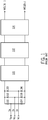
- FIG. 2 shows a block diagram of a welding-type system 200 that implements the preferred embodiment.
- System 200 includes an input circuit 201 that receives input power.
- Input circuit 201 may be implemented using an input rectifier, such as that known in the prior art.
- the input power is preferably from a variable speed engine and a variable frequency generator, but can be utility or generator power, single or three phase, and any voltage within a wide range of voltages.
- Alternatives provide for receiving a dc input which input circuit 201 can filter and pass through.
- Input circuit includes circuits configured to receive an ac input signal and to provide a dc output signal and may include as part thereof a rectifier, a transformer, a saturable reactor, a converter, an inverter, a filter, and/or a magnetic amplifier.
- System 200 also includes a preregulator 203 that receives the power signal from input circuit 201.
- Preregulator as used herein, includes circuitry such as rectifiers, switches, transformers, SCRs, etc. that process input power and/or software, control circuitry, feedback circuitry, communication circuitry, and other ancillary circuitry associated therewith.
- the preferred embodiment provides that preregulator 203 is a dual boost circuit preregulator.
- Dual boost circuit preregulator as used herein includes, is a circuit that receives an input and provides two boosted outputs, one across a common and positive bus, and the other across the common and a negative bus.
- Common bus as used herein includes, a bus that is used to power multiple outputs.
- Preregulator 203 can be implemented with a split boost circuit.
- Split boost circuit as used herein includes, a boosting circuit with two switches (or groups of switches) that control charging of two unparalleled capacitors, and a fixed bus is provided across the two capacitors.
- Preregulator 203 receives the rectified power from input circuit 201 and boosts the signal to provides a boosted split bus.
- preregulator 203 includes two boost inductors and two boost switches.
- Boost inductor is an inductor used in a circuit that boosts a voltage.
- Preregulator 203 also can provide power factor correction by proper timing of the boost switches.
- Alternatives provide for a single boost circuit, or other topologies such as buck converters, cuk converters, inverters etc.
- Preregulator 203 is controlled by a controller 211.
- Controller 211 includes the logic circuitry or chip that determines when the boost switches in preregulator 203 are turned turn on and off to produce the desired output voltage and/or power factor correction.
- Controller includes digital and analog circuitry, discrete or integrated circuitry, microprocessors, DSPs, FPGAs, etc., and software, hardware and firmware, located on one or more boards, used to control all or part of a welding-type system or a device such as a power supply, power source, engine or generator.
- Controller 211 receives feedback signals from preregulator 203, such as input current, out voltage, etc.
- the output of preregulator is provided to a dc bus filter 205 (the bulk capacitance on the dc bus). Feedback from filter 205 is provided to controller 211 and can be used to insure that the bus is at its desired level, and to determine if the split bus is balanced.
- the split, filtered dc bus is provided to an output converter 207 and to an auxiliary power circuit 209.
- Auxiliary power circuit includes circuitry used to provide auxiliary output power.
- Output converter 207 may be a single or multi-stage output circuit, and can include inverters, converters, transformers, etc.
- Output converter 207 is a welding-type power output circuit.
- Welding-type output power circuit includes, the circuitry used to deliver welding-type power to the output studs.
- Converter 207 receives the split dc bus, and provides a welding-type output.
- Preferably converter 207 is controlled in response to the demand for welding power.
- Welding type output power refers to output power suitable for welding, plasma cutting or induction heating.
- converter 207 be implemented using a pulse width modulated inverter, a transformer and a rectifier, to provide the desired output waveform and to provide isolation between the welding output and the input.
- a converter output is described in detail in the prior art discussed above.
- Other topologies may be used if desired.
- a chopper or buck converter is often used as an output circuit in welding-type power supplies.
- a second inverter can be used to provide an ac output.
- Converter 207 provides feedback signals to and receives control signals from controller 211.
- Auxiliary power circuit 209 is implemented in the preferred embodiment using two half-bridge inverters without an isolation transformer.
- Each inverter provides a 115VAC 60 Hz output, and together they provide a split phase AC output such as that provided by utility power.
- the ac aux outputs create a 230VAC aux power output across the two non-common outputs.
- the preferred embodiment provides that split phase ac aux power is provided, to more closely mimic utility power, and to provide both 115 and 230VAC aux power, and to do so without using an isolation transformer.
- Other embodiments provide for other outputs, such as 200/400V, 230/460V, or 50 Hz.
- Alternatives include providing non-split phase auxiliary power without an isolation transformer
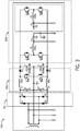
- FIG 3 is a circuit diagram showing more detail for portions of welding-type system 200, including input circuit 201, preregulator 203, dc bus filter 205, and auxiliary power circuit 209.
- Welding type system 200 receives as an input single phase power.
- Alternatives provide for a three phase input, and one skilled in the art can configure system 200 to receive three phase power.
- the power may be from a utility source, or from an engine/generator 215 (shown in Figure 2 ).
- generator 215 provides 10KW of power at 3600 RPM.
- a 230VAC signal may be provided from generator 215 on the H, N, and H connections on Figure 3 .
- Engine/generator 215 preferably includes a variable speed engine, and the speed is preferably controlled by controller 215 in response to the power demand of system 200. Specifically, the speed is controlled in response to the demand for auxiliary power and/or the demand for welding power.
- Engine/generator 215 may be a variable frequency generator, and the frequency is controlled by controller 215.
- Alternatives provide for a controller that is part of and unique to engine/generator 215, and/or a multi-speed or single speed engine and a constant frequency generator and/or variable voltage generator.
- the input is rectified by input circuit 201, which includes diodes D1-D4, in the preferred embodiment.
- the rectified DC signal from input circuit 201 is provided to filter capacitors C1 and C2 (preferably 2 ⁇ F), and then to preregulator 203. Capacitors C1 and C2 prevent ripple from being injected into the input.
- Preregulator 203 is a dual split boost and includes boost inductors L1 and L2 (preferably 50 ⁇ H) and switches Q1 and Q2. Switches Q and Q2 are controlled by controller 211 to provide a desired bus voltage and, preferably, power factor correction.
- preregulator 203 The output of preregulator 203 is provided through diodes D5 and D6 across bus capacitors C3 and C4 (preferably 3000 ⁇ F and rated for 250V).
- the common node of capacitors C4 and C5 is neutral, thus the output is a split bus.
- the bus is provided to the welding output converter 207 ( Figure 2 ) and to auxiliary power circuit 209.
- Auxiliary power circuit 209 is comprised of, in the preferred embodiment, two 20KHz half bridge inverters.
- Each inverter is comprised of two switches (Q3, Q4 and Q5,Q6, preferably IGBTs or FETs), an inductor (L3 and L4, preferably 200 ⁇ H), and a capacitor C5, C6 (preferably 15 ⁇ F).
- Each inverters output is provide across a unique hot output and a common neutral output.
- the inverters are pulse width modulated by controller 211 to provide a 115VAC sinusoidal output, and are 180 degrees out of phase from one another to provide a split phase auxiliary power output.
- the output of each inverter mimics a 115V utility signal, and combined they mimic a 230VAC utility signal.
- the output is a non-isolated auxiliary output.
- the inverters are preferably controlled in response to the demand for auxiliary power.
Landscapes
- Engineering & Computer Science (AREA)
- Physics & Mathematics (AREA)
- Plasma & Fusion (AREA)
- Mechanical Engineering (AREA)
- Arc Welding Control (AREA)
- Inverter Devices (AREA)
- Dc-Dc Converters (AREA)
Claims (10)
- Schweißstromversorgung (200), umfassend:- eine Eingangsschaltung (201), die dafür ausgelegt ist, Eingangsleistung aufzunehmen und Busleistung an einen gemeinsamen Bus abzugeben;- eine Schweißausgangsleistungs-Schaltung (207), die dafür ausgelegt ist, Leistung vom gemeinsamen Bus aufzunehmen und Leistung an einen Schweißausgang bereitzustellen;- eine Hilfsleistungsschaltung (209), die dafür ausgelegt ist, Leistung vom gemeinsamen Bus aufzunehmen und eine nicht isolierte Hilfsausgangsleistung bereitzustellen; und- eine Steuerung, die zur Steuerung der Hilfsleistungsschaltung (209) und der Schweißausgangsleistungs-Schaltung (207) angeschlossen ist,
wobei die Eingangsschaltung (201) einen Gleichrichter aufweist,
dadurch gekennzeichnet, dass
die Eingangsschaltung (201) einen Vorregler (203) für eine Dual-Boost-Schaltung aufweist,
und
wobei die Hilfsleistungsschaltung (209) einen zweiphasigen Ausgang bereitstellt. - Schweißstromversorgung (200) nach Anspruch 1, ferner einen Motor, der Antriebsleistung bereitstellt, und einen Generator (215), der die Antriebsleistung aufnimmt und die Eingangsleistung bereitstellt, umfassend.
- Schweißstromversorgung (200) nach Anspruch 2, wobei der Motor ein drehzahlvariabler Motor ist.
- Schweißstromversorgung (200) nach Anspruch 3, wobei die Steuerung angeschlossen ist, um die Drehzahl des drehzahlvariablen Motors zu steuern.
- Schweißstromversorgung (200) nach Anspruch 4, wobei der Generator (215) ein frequenzvariabler Generator (215) ist.
- Schweißstromversorgung (200) nach Anspruch 5, wobei die Steuerung zur Steuerung der Frequenz des frequenzvariablen Generators (215) angeschlossen ist.
- Verfahren zum Bereitstellen von Schweißleistung, umfassend:- Empfangen von Eingangsleistung;- Bereitstellen von Zwischenleistung an einen gemeinsamen Bus;- Ableiten der Schweißausgangsleistung vom gemeinsamen Bus;- Bereitstellen der Schweißleistung an einem Schweißausgang;- Ableiten der nicht isolierten Hilfsleistung vom gemeinsamen Bus;- Bereitstellen von nicht isolierter Hilfsleistung an einem Hilfsleistungsausgang;- Steuern der Ableitung der nicht isolierten Hilfsleistung in Reaktion auf eine Hilfsanforderung für die nicht isolierte Hilfsleistung; und- Steuern der Ableitung der Schweißausgangsleistung in Reaktion auf eine Schweißanforderung der Schweißausgangsleistung,
wobei das Bereitstellen von Zwischenleistung die Gleichrichtung der Eingangsleistung beinhaltet, dadurch gekennzeichnet, dass
das Bereitstellen der Zwischenleistung die Vorregelung der Eingangsleistung mittels eines Vorreglers der Boost-Schaltung (203) beinhaltet, und
wobei das Bereitstellen der nicht isolierten Hilfsausgangsleistung die Bereitstellung eines zweiphasigen Ausgangs beinhaltet. - Verfahren nach Anspruch 7,
ferner umfassend das Bereitstellen von Antriebsleistung an einen Generator (215) und das Erzeugen der Eingangsleistung mit dem Generator (215). - Verfahren nach Anspruch 8,
wobei das Bereitstellen von Antriebsleistung die Steuerung der Drehzahl eines drehzahlvariablen Motors in Reaktion auf wenigstens entweder die Anforderung der nicht isolierten Hilfsleistung und/oder die Anforderung der Schweißleistung beinhaltet. - Verfahren nach Anspruch 9,
wobei das Erzeugen der Eingangsleistung die Erzeugung der Eingangsleistung mit einer variablen Frequenz in Reaktion auf wenigstens entweder die Anforderung der nicht isolierten Hilfsleistung und/oder die Anforderung der Schweißleistung beinhaltet.
Applications Claiming Priority (2)
| Application Number | Priority Date | Filing Date | Title |
|---|---|---|---|
| US14/636,315 US9808881B2 (en) | 2015-03-03 | 2015-03-03 | Method and apparatus for providing welding and auxiliary power |
| PCT/US2016/020623 WO2016141149A1 (en) | 2015-03-03 | 2016-03-03 | Method and apparatus for providing welding and auxiliary power |
Publications (2)
| Publication Number | Publication Date |
|---|---|
| EP3265262A1 EP3265262A1 (de) | 2018-01-10 |
| EP3265262B1 true EP3265262B1 (de) | 2020-05-27 |
Family
ID=55524475
Family Applications (1)
| Application Number | Title | Priority Date | Filing Date |
|---|---|---|---|
| EP16709662.7A Not-in-force EP3265262B1 (de) | 2015-03-03 | 2016-03-03 | Verfahren und vorrichtung zur bereitstellung von schweissstrom und hilfsstrom |
Country Status (4)
| Country | Link |
|---|---|
| US (2) | US9808881B2 (de) |
| EP (1) | EP3265262B1 (de) |
| CN (1) | CN107635712A (de) |
| WO (1) | WO2016141149A1 (de) |
Families Citing this family (10)
| Publication number | Priority date | Publication date | Assignee | Title |
|---|---|---|---|---|
| US9997917B2 (en) | 2015-07-01 | 2018-06-12 | Google Llc | Transformerless power conversion |
| ES3041928T3 (en) * | 2015-12-22 | 2025-11-17 | Thermatool Corp | High frequency power supply system with closely regulated output for heating a workpiece |
| US10608551B2 (en) * | 2017-08-02 | 2020-03-31 | Stmicroelectronics (Tours) Sas | Rectifying element and voltage converter comprising such a rectifying element |
| US11253942B2 (en) * | 2017-09-08 | 2022-02-22 | Illinois Tool Works Inc. | Methods and apparatus for automatic control of a welding-type power supply |
| US10907627B2 (en) | 2017-10-30 | 2021-02-02 | Illinois Tool Works Inc. | Systems and methods for running an air compressor using a permanent magnet generator |
| US10393082B2 (en) | 2017-10-30 | 2019-08-27 | Illinois Tool Works Inc. | Systems and methods for starting an engine using a permanent magnet generator |
| US10875118B2 (en) * | 2017-11-13 | 2020-12-29 | Illinois Tool Works Inc. | Engine driven generator for providing welding power |
| US10926346B2 (en) * | 2018-06-20 | 2021-02-23 | Antaya Technologies Corporation | Resistance soldering system |
| US11839939B2 (en) * | 2018-09-27 | 2023-12-12 | Illinois Tool Works Inc. | Systems, methods, and apparatus for pre-regulator control in welding-type power supplies |
| EP3719982B8 (de) * | 2019-04-02 | 2022-12-21 | ABB E-mobility B.V. | Dreiphasiger wechselstrom-gleichstrom-leistungswandler |
Citations (2)
| Publication number | Priority date | Publication date | Assignee | Title |
|---|---|---|---|---|
| US20140021180A1 (en) * | 2012-07-23 | 2014-01-23 | Illinois Tool Works Inc. | Method and Apparatus For Providing Welding Type Power |
| US20150053660A1 (en) * | 2012-07-23 | 2015-02-26 | Illinois Tool Works Inc. | Method and Apparatus For Providing Welding Type Power With Flux Balancing |
Family Cites Families (12)
| Publication number | Priority date | Publication date | Assignee | Title |
|---|---|---|---|---|
| US5601741A (en) | 1994-11-18 | 1997-02-11 | Illinois Tool Works, Inc. | Method and apparatus for receiving a universal input voltage in a welding power source |
| JP3078245B2 (ja) * | 1997-08-06 | 2000-08-21 | 松下電器産業株式会社 | アークスタート補助装置 |
| US6329636B1 (en) | 2000-03-31 | 2001-12-11 | Illinois Tool Works Inc. | Method and apparatus for receiving a universal input voltage in a welding plasma or heating power source |
| JP2004314098A (ja) * | 2003-04-14 | 2004-11-11 | Daihen Corp | アーク溶接機 |
| US7858904B2 (en) | 2005-01-20 | 2010-12-28 | Illinois Tool Works Inc. | System and method of controlling auxiliary/weld power outputs of a welding-type apparatus |
| US8822884B2 (en) * | 2007-08-07 | 2014-09-02 | Lincoln Global, Inc. | Welding apparatus providing auxiliary power |
| US8952293B2 (en) | 2008-03-14 | 2015-02-10 | Illinois Tool Works Inc. | Welding or cutting power supply using phase shift double forward converter circuit (PSDF) |
| US8115328B2 (en) * | 2009-01-30 | 2012-02-14 | Illinois Tool Works Inc. | Weld setting based engine-driven generator control system and method |
| US8502115B2 (en) | 2009-06-11 | 2013-08-06 | Illinois Tool Works Inc. | Engine driven welder-generator with chopper circuit |
| US9399261B2 (en) | 2013-03-13 | 2016-07-26 | Illinois Tool Works Inc. | Hybrid welding control technique |
| US10369651B2 (en) | 2013-03-15 | 2019-08-06 | Illinois Tool Works Inc. | Method and apparatus for providing welding-type power and auxiliary power |
| US20160175968A1 (en) * | 2014-12-19 | 2016-06-23 | Illinois Tool Works Inc. | Method and apparatus for providing welding and auxiliary power |
-
2015
- 2015-03-03 US US14/636,315 patent/US9808881B2/en active Active
-
2016
- 2016-03-03 EP EP16709662.7A patent/EP3265262B1/de not_active Not-in-force
- 2016-03-03 WO PCT/US2016/020623 patent/WO2016141149A1/en not_active Ceased
- 2016-03-03 CN CN201680013428.7A patent/CN107635712A/zh active Pending
-
2017
- 2017-10-16 US US15/785,289 patent/US10035212B2/en active Active
Patent Citations (2)
| Publication number | Priority date | Publication date | Assignee | Title |
|---|---|---|---|---|
| US20140021180A1 (en) * | 2012-07-23 | 2014-01-23 | Illinois Tool Works Inc. | Method and Apparatus For Providing Welding Type Power |
| US20150053660A1 (en) * | 2012-07-23 | 2015-02-26 | Illinois Tool Works Inc. | Method and Apparatus For Providing Welding Type Power With Flux Balancing |
Also Published As
| Publication number | Publication date |
|---|---|
| CN107635712A (zh) | 2018-01-26 |
| US9808881B2 (en) | 2017-11-07 |
| US10035212B2 (en) | 2018-07-31 |
| US20180050411A1 (en) | 2018-02-22 |
| EP3265262A1 (de) | 2018-01-10 |
| WO2016141149A1 (en) | 2016-09-09 |
| US20160256950A1 (en) | 2016-09-08 |
Similar Documents
| Publication | Publication Date | Title |
|---|---|---|
| EP3265262B1 (de) | Verfahren und vorrichtung zur bereitstellung von schweissstrom und hilfsstrom | |
| EP3235115B1 (de) | Verfahren und vorrichtung zur bereitstellung von schweiss- und hilfsstrom | |
| US12186841B2 (en) | Method and apparatus for providing welding type power with flux balancing | |
| US11097369B2 (en) | Method and apparatus for providing welding type power | |
| CN107078662B (zh) | 包括用于在电弧焊机中提供电力的平衡dc总线的方法和设备 | |
| US20220023964A1 (en) | Method and Apparatus For Providing Welding Power | |
| US10625360B2 (en) | Method and apparatus for providing welding type power | |
| EP3215298B1 (de) | Verfahren und gerät mit transformatorflusssymmetrierung für die leistungsversorgung für schweissanwendungen |
Legal Events
| Date | Code | Title | Description |
|---|---|---|---|
| STAA | Information on the status of an ep patent application or granted ep patent |
Free format text: STATUS: THE INTERNATIONAL PUBLICATION HAS BEEN MADE |
|
| PUAI | Public reference made under article 153(3) epc to a published international application that has entered the european phase |
Free format text: ORIGINAL CODE: 0009012 |
|
| STAA | Information on the status of an ep patent application or granted ep patent |
Free format text: STATUS: REQUEST FOR EXAMINATION WAS MADE |
|
| 17P | Request for examination filed |
Effective date: 20170816 |
|
| AK | Designated contracting states |
Kind code of ref document: A1 Designated state(s): AL AT BE BG CH CY CZ DE DK EE ES FI FR GB GR HR HU IE IS IT LI LT LU LV MC MK MT NL NO PL PT RO RS SE SI SK SM TR |
|
| AX | Request for extension of the european patent |
Extension state: BA ME |
|
| DAV | Request for validation of the european patent (deleted) | ||
| DAX | Request for extension of the european patent (deleted) | ||
| STAA | Information on the status of an ep patent application or granted ep patent |
Free format text: STATUS: EXAMINATION IS IN PROGRESS |
|
| 17Q | First examination report despatched |
Effective date: 20190418 |
|
| GRAP | Despatch of communication of intention to grant a patent |
Free format text: ORIGINAL CODE: EPIDOSNIGR1 |
|
| STAA | Information on the status of an ep patent application or granted ep patent |
Free format text: STATUS: GRANT OF PATENT IS INTENDED |
|
| INTG | Intention to grant announced |
Effective date: 20191217 |
|
| GRAS | Grant fee paid |
Free format text: ORIGINAL CODE: EPIDOSNIGR3 |
|
| GRAA | (expected) grant |
Free format text: ORIGINAL CODE: 0009210 |
|
| STAA | Information on the status of an ep patent application or granted ep patent |
Free format text: STATUS: THE PATENT HAS BEEN GRANTED |
|
| AK | Designated contracting states |
Kind code of ref document: B1 Designated state(s): AL AT BE BG CH CY CZ DE DK EE ES FI FR GB GR HR HU IE IS IT LI LT LU LV MC MK MT NL NO PL PT RO RS SE SI SK SM TR |
|
| REG | Reference to a national code |
Ref country code: GB Ref legal event code: FG4D |
|
| REG | Reference to a national code |
Ref country code: CH Ref legal event code: EP |
|
| REG | Reference to a national code |
Ref country code: DE Ref legal event code: R096 Ref document number: 602016037001 Country of ref document: DE |
|
| REG | Reference to a national code |
Ref country code: AT Ref legal event code: REF Ref document number: 1274061 Country of ref document: AT Kind code of ref document: T Effective date: 20200615 |
|
| REG | Reference to a national code |
Ref country code: LT Ref legal event code: MG4D |
|
| PG25 | Lapsed in a contracting state [announced via postgrant information from national office to epo] |
Ref country code: LT Free format text: LAPSE BECAUSE OF FAILURE TO SUBMIT A TRANSLATION OF THE DESCRIPTION OR TO PAY THE FEE WITHIN THE PRESCRIBED TIME-LIMIT Effective date: 20200527 Ref country code: SE Free format text: LAPSE BECAUSE OF FAILURE TO SUBMIT A TRANSLATION OF THE DESCRIPTION OR TO PAY THE FEE WITHIN THE PRESCRIBED TIME-LIMIT Effective date: 20200527 Ref country code: FI Free format text: LAPSE BECAUSE OF FAILURE TO SUBMIT A TRANSLATION OF THE DESCRIPTION OR TO PAY THE FEE WITHIN THE PRESCRIBED TIME-LIMIT Effective date: 20200527 Ref country code: PT Free format text: LAPSE BECAUSE OF FAILURE TO SUBMIT A TRANSLATION OF THE DESCRIPTION OR TO PAY THE FEE WITHIN THE PRESCRIBED TIME-LIMIT Effective date: 20200928 Ref country code: IS Free format text: LAPSE BECAUSE OF FAILURE TO SUBMIT A TRANSLATION OF THE DESCRIPTION OR TO PAY THE FEE WITHIN THE PRESCRIBED TIME-LIMIT Effective date: 20200927 Ref country code: GR Free format text: LAPSE BECAUSE OF FAILURE TO SUBMIT A TRANSLATION OF THE DESCRIPTION OR TO PAY THE FEE WITHIN THE PRESCRIBED TIME-LIMIT Effective date: 20200828 Ref country code: NO Free format text: LAPSE BECAUSE OF FAILURE TO SUBMIT A TRANSLATION OF THE DESCRIPTION OR TO PAY THE FEE WITHIN THE PRESCRIBED TIME-LIMIT Effective date: 20200827 |
|
| REG | Reference to a national code |
Ref country code: NL Ref legal event code: MP Effective date: 20200527 |
|
| PG25 | Lapsed in a contracting state [announced via postgrant information from national office to epo] |
Ref country code: RS Free format text: LAPSE BECAUSE OF FAILURE TO SUBMIT A TRANSLATION OF THE DESCRIPTION OR TO PAY THE FEE WITHIN THE PRESCRIBED TIME-LIMIT Effective date: 20200527 Ref country code: LV Free format text: LAPSE BECAUSE OF FAILURE TO SUBMIT A TRANSLATION OF THE DESCRIPTION OR TO PAY THE FEE WITHIN THE PRESCRIBED TIME-LIMIT Effective date: 20200527 Ref country code: BG Free format text: LAPSE BECAUSE OF FAILURE TO SUBMIT A TRANSLATION OF THE DESCRIPTION OR TO PAY THE FEE WITHIN THE PRESCRIBED TIME-LIMIT Effective date: 20200827 Ref country code: HR Free format text: LAPSE BECAUSE OF FAILURE TO SUBMIT A TRANSLATION OF THE DESCRIPTION OR TO PAY THE FEE WITHIN THE PRESCRIBED TIME-LIMIT Effective date: 20200527 |
|
| REG | Reference to a national code |
Ref country code: AT Ref legal event code: MK05 Ref document number: 1274061 Country of ref document: AT Kind code of ref document: T Effective date: 20200527 |
|
| PG25 | Lapsed in a contracting state [announced via postgrant information from national office to epo] |
Ref country code: NL Free format text: LAPSE BECAUSE OF FAILURE TO SUBMIT A TRANSLATION OF THE DESCRIPTION OR TO PAY THE FEE WITHIN THE PRESCRIBED TIME-LIMIT Effective date: 20200527 Ref country code: AL Free format text: LAPSE BECAUSE OF FAILURE TO SUBMIT A TRANSLATION OF THE DESCRIPTION OR TO PAY THE FEE WITHIN THE PRESCRIBED TIME-LIMIT Effective date: 20200527 |
|
| PG25 | Lapsed in a contracting state [announced via postgrant information from national office to epo] |
Ref country code: CZ Free format text: LAPSE BECAUSE OF FAILURE TO SUBMIT A TRANSLATION OF THE DESCRIPTION OR TO PAY THE FEE WITHIN THE PRESCRIBED TIME-LIMIT Effective date: 20200527 Ref country code: RO Free format text: LAPSE BECAUSE OF FAILURE TO SUBMIT A TRANSLATION OF THE DESCRIPTION OR TO PAY THE FEE WITHIN THE PRESCRIBED TIME-LIMIT Effective date: 20200527 Ref country code: SM Free format text: LAPSE BECAUSE OF FAILURE TO SUBMIT A TRANSLATION OF THE DESCRIPTION OR TO PAY THE FEE WITHIN THE PRESCRIBED TIME-LIMIT Effective date: 20200527 Ref country code: IT Free format text: LAPSE BECAUSE OF FAILURE TO SUBMIT A TRANSLATION OF THE DESCRIPTION OR TO PAY THE FEE WITHIN THE PRESCRIBED TIME-LIMIT Effective date: 20200527 Ref country code: EE Free format text: LAPSE BECAUSE OF FAILURE TO SUBMIT A TRANSLATION OF THE DESCRIPTION OR TO PAY THE FEE WITHIN THE PRESCRIBED TIME-LIMIT Effective date: 20200527 Ref country code: AT Free format text: LAPSE BECAUSE OF FAILURE TO SUBMIT A TRANSLATION OF THE DESCRIPTION OR TO PAY THE FEE WITHIN THE PRESCRIBED TIME-LIMIT Effective date: 20200527 Ref country code: DK Free format text: LAPSE BECAUSE OF FAILURE TO SUBMIT A TRANSLATION OF THE DESCRIPTION OR TO PAY THE FEE WITHIN THE PRESCRIBED TIME-LIMIT Effective date: 20200527 Ref country code: ES Free format text: LAPSE BECAUSE OF FAILURE TO SUBMIT A TRANSLATION OF THE DESCRIPTION OR TO PAY THE FEE WITHIN THE PRESCRIBED TIME-LIMIT Effective date: 20200527 |
|
| PG25 | Lapsed in a contracting state [announced via postgrant information from national office to epo] |
Ref country code: SK Free format text: LAPSE BECAUSE OF FAILURE TO SUBMIT A TRANSLATION OF THE DESCRIPTION OR TO PAY THE FEE WITHIN THE PRESCRIBED TIME-LIMIT Effective date: 20200527 Ref country code: PL Free format text: LAPSE BECAUSE OF FAILURE TO SUBMIT A TRANSLATION OF THE DESCRIPTION OR TO PAY THE FEE WITHIN THE PRESCRIBED TIME-LIMIT Effective date: 20200527 |
|
| REG | Reference to a national code |
Ref country code: DE Ref legal event code: R097 Ref document number: 602016037001 Country of ref document: DE |
|
| PLBE | No opposition filed within time limit |
Free format text: ORIGINAL CODE: 0009261 |
|
| STAA | Information on the status of an ep patent application or granted ep patent |
Free format text: STATUS: NO OPPOSITION FILED WITHIN TIME LIMIT |
|
| 26N | No opposition filed |
Effective date: 20210302 |
|
| PG25 | Lapsed in a contracting state [announced via postgrant information from national office to epo] |
Ref country code: SI Free format text: LAPSE BECAUSE OF FAILURE TO SUBMIT A TRANSLATION OF THE DESCRIPTION OR TO PAY THE FEE WITHIN THE PRESCRIBED TIME-LIMIT Effective date: 20200527 |
|
| REG | Reference to a national code |
Ref country code: DE Ref legal event code: R119 Ref document number: 602016037001 Country of ref document: DE |
|
| PG25 | Lapsed in a contracting state [announced via postgrant information from national office to epo] |
Ref country code: MC Free format text: LAPSE BECAUSE OF FAILURE TO SUBMIT A TRANSLATION OF THE DESCRIPTION OR TO PAY THE FEE WITHIN THE PRESCRIBED TIME-LIMIT Effective date: 20200527 |
|
| REG | Reference to a national code |
Ref country code: CH Ref legal event code: PL |
|
| GBPC | Gb: european patent ceased through non-payment of renewal fee |
Effective date: 20210303 |
|
| REG | Reference to a national code |
Ref country code: BE Ref legal event code: MM Effective date: 20210331 |
|
| PG25 | Lapsed in a contracting state [announced via postgrant information from national office to epo] |
Ref country code: DE Free format text: LAPSE BECAUSE OF NON-PAYMENT OF DUE FEES Effective date: 20211001 Ref country code: LI Free format text: LAPSE BECAUSE OF NON-PAYMENT OF DUE FEES Effective date: 20210331 Ref country code: LU Free format text: LAPSE BECAUSE OF NON-PAYMENT OF DUE FEES Effective date: 20210303 Ref country code: CH Free format text: LAPSE BECAUSE OF NON-PAYMENT OF DUE FEES Effective date: 20210331 Ref country code: IE Free format text: LAPSE BECAUSE OF NON-PAYMENT OF DUE FEES Effective date: 20210303 Ref country code: FR Free format text: LAPSE BECAUSE OF NON-PAYMENT OF DUE FEES Effective date: 20210331 Ref country code: GB Free format text: LAPSE BECAUSE OF NON-PAYMENT OF DUE FEES Effective date: 20210303 |
|
| PG25 | Lapsed in a contracting state [announced via postgrant information from national office to epo] |
Ref country code: BE Free format text: LAPSE BECAUSE OF NON-PAYMENT OF DUE FEES Effective date: 20210331 |
|
| PG25 | Lapsed in a contracting state [announced via postgrant information from national office to epo] |
Ref country code: CY Free format text: LAPSE BECAUSE OF FAILURE TO SUBMIT A TRANSLATION OF THE DESCRIPTION OR TO PAY THE FEE WITHIN THE PRESCRIBED TIME-LIMIT Effective date: 20200527 |
|
| PG25 | Lapsed in a contracting state [announced via postgrant information from national office to epo] |
Ref country code: HU Free format text: LAPSE BECAUSE OF FAILURE TO SUBMIT A TRANSLATION OF THE DESCRIPTION OR TO PAY THE FEE WITHIN THE PRESCRIBED TIME-LIMIT; INVALID AB INITIO Effective date: 20160303 |
|
| PG25 | Lapsed in a contracting state [announced via postgrant information from national office to epo] |
Ref country code: MK Free format text: LAPSE BECAUSE OF FAILURE TO SUBMIT A TRANSLATION OF THE DESCRIPTION OR TO PAY THE FEE WITHIN THE PRESCRIBED TIME-LIMIT Effective date: 20200527 |
|
| PG25 | Lapsed in a contracting state [announced via postgrant information from national office to epo] |
Ref country code: TR Free format text: LAPSE BECAUSE OF FAILURE TO SUBMIT A TRANSLATION OF THE DESCRIPTION OR TO PAY THE FEE WITHIN THE PRESCRIBED TIME-LIMIT Effective date: 20200527 |
|
| PG25 | Lapsed in a contracting state [announced via postgrant information from national office to epo] |
Ref country code: MT Free format text: LAPSE BECAUSE OF FAILURE TO SUBMIT A TRANSLATION OF THE DESCRIPTION OR TO PAY THE FEE WITHIN THE PRESCRIBED TIME-LIMIT Effective date: 20200527 |