EP3265332B1 - System zur immobilisierung einer auswechselbaren kassette in einem gehäuse - Google Patents
System zur immobilisierung einer auswechselbaren kassette in einem gehäuse Download PDFInfo
- Publication number
- EP3265332B1 EP3265332B1 EP16701130.3A EP16701130A EP3265332B1 EP 3265332 B1 EP3265332 B1 EP 3265332B1 EP 16701130 A EP16701130 A EP 16701130A EP 3265332 B1 EP3265332 B1 EP 3265332B1
- Authority
- EP
- European Patent Office
- Prior art keywords
- cartridge
- housing
- bar
- trigger
- assembly according
- Prior art date
- Legal status (The legal status is an assumption and is not a legal conclusion. Google has not performed a legal analysis and makes no representation as to the accuracy of the status listed.)
- Active
Links
Images


Classifications
-
- B—PERFORMING OPERATIONS; TRANSPORTING
- B60—VEHICLES IN GENERAL
- B60H—ARRANGEMENTS OF HEATING, COOLING, VENTILATING OR OTHER AIR-TREATING DEVICES SPECIALLY ADAPTED FOR PASSENGER OR GOODS SPACES OF VEHICLES
- B60H3/00—Other air-treating devices
- B60H3/0007—Adding substances other than water to the air, e.g. perfume, oxygen
- B60H3/0035—Adding substances other than water to the air, e.g. perfume, oxygen characterised by the control methods for adding the substance
-
- A—HUMAN NECESSITIES
- A61—MEDICAL OR VETERINARY SCIENCE; HYGIENE
- A61L—METHODS OR APPARATUS FOR STERILISING MATERIALS OR OBJECTS IN GENERAL; DISINFECTION, STERILISATION OR DEODORISATION OF AIR; CHEMICAL ASPECTS OF BANDAGES, DRESSINGS, ABSORBENT PADS OR SURGICAL ARTICLES; MATERIALS FOR BANDAGES, DRESSINGS, ABSORBENT PADS OR SURGICAL ARTICLES
- A61L9/00—Disinfection, sterilisation or deodorisation of air
- A61L9/015—Disinfection, sterilisation or deodorisation of air using gaseous or vaporous substances, e.g. ozone
- A61L9/04—Disinfection, sterilisation or deodorisation of air using gaseous or vaporous substances, e.g. ozone using substances evaporated in the air without heating
- A61L9/12—Apparatus, e.g. holders, therefor
-
- A—HUMAN NECESSITIES
- A61—MEDICAL OR VETERINARY SCIENCE; HYGIENE
- A61L—METHODS OR APPARATUS FOR STERILISING MATERIALS OR OBJECTS IN GENERAL; DISINFECTION, STERILISATION OR DEODORISATION OF AIR; CHEMICAL ASPECTS OF BANDAGES, DRESSINGS, ABSORBENT PADS OR SURGICAL ARTICLES; MATERIALS FOR BANDAGES, DRESSINGS, ABSORBENT PADS OR SURGICAL ARTICLES
- A61L2209/00—Aspects relating to disinfection, sterilisation or deodorisation of air
- A61L2209/10—Apparatus features
- A61L2209/13—Dispensing or storing means for active compounds
- A61L2209/133—Replaceable cartridges, refills
-
- A—HUMAN NECESSITIES
- A61—MEDICAL OR VETERINARY SCIENCE; HYGIENE
- A61L—METHODS OR APPARATUS FOR STERILISING MATERIALS OR OBJECTS IN GENERAL; DISINFECTION, STERILISATION OR DEODORISATION OF AIR; CHEMICAL ASPECTS OF BANDAGES, DRESSINGS, ABSORBENT PADS OR SURGICAL ARTICLES; MATERIALS FOR BANDAGES, DRESSINGS, ABSORBENT PADS OR SURGICAL ARTICLES
- A61L2209/00—Aspects relating to disinfection, sterilisation or deodorisation of air
- A61L2209/10—Apparatus features
- A61L2209/15—Supporting means, e.g. stands, hooks, holes for hanging
-
- A—HUMAN NECESSITIES
- A61—MEDICAL OR VETERINARY SCIENCE; HYGIENE
- A61L—METHODS OR APPARATUS FOR STERILISING MATERIALS OR OBJECTS IN GENERAL; DISINFECTION, STERILISATION OR DEODORISATION OF AIR; CHEMICAL ASPECTS OF BANDAGES, DRESSINGS, ABSORBENT PADS OR SURGICAL ARTICLES; MATERIALS FOR BANDAGES, DRESSINGS, ABSORBENT PADS OR SURGICAL ARTICLES
- A61L2209/00—Aspects relating to disinfection, sterilisation or deodorisation of air
- A61L2209/10—Apparatus features
- A61L2209/16—Connections to a HVAC unit
Definitions
- the present invention relates to a system for immobilizing a removable cartridge in a casing, in particular intended for use in a delivery device forming part of a motor vehicle.
- Devices comprising a housing and provided with a removable cartridge and a button for locking said removable element relative to the housing are known.
- the object of the invention is to improve the situation and to this end proposes an assembly comprising a system for immobilizing a removable cartridge in a housing and said removable cartridge, according to the characteristics of claim 1.
- the immobilization system of the cartridge according to the invention comprises trigger, allowing in a first position, the maintenance of said cartridge in said housing, and in a second position, the introduction/extraction of said cartridge relative to said housing, said trigger being operable in translation in a direction transverse to an insertion/extraction direction of the cartridge.
- said trigger comprises a bar for blocking the cartridge, said bar comprising at least one abutment for blocking the cartridge, the said abutment(s) being intended to cooperate with one or more blocking pins of the said cartridge. , the said blocking pin(s) being provided with a cutaway intended to cause an actuation in translation of the bar during the introduction of the cartridge.
- the invention also relates to a broadcasting device comprising an assembly as described above.
- the invention relates to a system for immobilizing a removable cartridge in a housing, in particular for a diffusion device allowing the treatment of an air flow using volatile agents, especially fragrances.
- the volatile agents in particular the fragrances, comprise a substrate, in particular beads, loaded with volatile compound(s). It may in particular be fragrant balls.
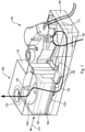
- the diffusion device or diffuser is illustrated as a whole. It comprises here a housing 100 on which two orifices serve as inlet 105 and outlet 110 of the air. From then on, the housing serves as an air guide and includes a plurality of components that will allow air to flow through the case. Preferably, an interface on the orifices 105, 110 allows tubing, not shown, to be attached thereto while ensuring the airtightness of the system.
- the diffuser comprises a cartridge 130 of fragrances and a selector, here housed in said housing 100.
- the selector comprises, for example, an input selector 125a, an output selector 125b and a movable shaft 135 driving them.
- Said diffuser further comprises here an actuation mechanism 150, allowing said shaft 135 to be driven.
- the box 100 can be fixed at different locations of the vehicle, preferably on the dashboard or in the glove box so that the latter is easily accessible to the passenger.
- the cartridge is removable relative to said housing and it is advantageous for the passenger to be able to easily change the cartridge.
- the air outlet of the box 110 is connected, for example, to a grille through which the treated or scented air exits.
- This grille can be attached to different locations in the vehicle. Preferably, it is located on the dashboard or near the ventilation systems of the windshield, the grid being connected to the outlet of the housing by the pipe already mentioned.
- the box 100 comprises a base 180, for example a rectangular parallelepiped.
- a pulser 115 located above the inlet 105 of the housing and at least part of the actuating mechanism 150.
- Said actuating mechanism may comprise a motor 140.
- the latter is fixed to the housing 100 above the pulser 115, and is located outside the housing.
- a second part of the housing 170 has a substantially cubic shape to house the fragrance selector and the cartridge 130 therein. housing parts are assembled together. Airtightness is ensured throughout the housing.
- the inlet 105 is therefore in the base 180 of the housing 100, on the lower face and below the pulser 115.
- the outlet orifice 110 is on the upper face of the second part 170, above the selector output 125b.
- This blower generates the air flow which will finally leave the box through the outlet orifice 110 after passing through the cartridge. 130.
- Airflow is illustrated by line 120 on the figure 1 .
- the pulser 115 is of the radial type, but it can also be of the axial type.
- the cartridge 130 is advantageously composed of a plurality of cavities in which different fragrances can be housed.
- the selector 125a, 125b is configured so that one or more of these cavities are crossed by the flow of air so that the latter is charged with the volatile compounds of the fragrance(s) selected.
- the air flow passes through said selected cavity or cavities, the air comes into contact with all of the substrate contained in each of said cavities and said substrate releases the compound or compounds which will perfume and/or treat the flow. of air, and then the passenger compartment of the motor vehicle.
- the air flow 120 enters the cartridge 130 through an input of the input selector.
- the air flow then crosses the cartridge 130 right through passing through one or more of the cavities of said cartridge which it leaves through an outlet of said outlet selector 125b.
- optimized loading of the airflow by the fragrance is ensured, the latter coming into contact with the entire surface of the associated substrate.
- the air flow is here guided to the outlet orifice 110 of the housing.
- the blower 115 allows the device to be independent of the ventilation, air conditioning or heating system with which the vehicle may be equipped. It can therefore be used independently of these systems, which makes it all the more flexible in use.
- it is connected to the ventilation, air conditioning or heating system of the vehicle.
- the inlet 105 and outlet 110 would in this embodiment be connected to a conduit of said system.
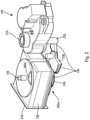
- the picture 2 provides a more detailed view of the figure 1 without the box 100.
- the picture 2 illustrates the details of the actuation mechanism 150, the movable shaft 135 and the input 125a and output 125b selector.
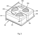
- the 130 cartridge is shown in more detail on the picture 3 .
- the actuation mechanism 150 comprises for example the motor 140, a shaft 220, a transmission pinion 230, advantageously allowing a reduction, and a spur gear 240.
- the motor 140 drives the kinematics of the elements located downstream: the shaft 220 , directly connected to an actuator of the motor, drives the transmission pinion 230, which drives the spur gear 240.
- the movable shaft 135 is directly fixed on the spur gear 240 and is therefore also driven by the latter.
- the input selector 125a and the output selector 125b are in the form of turntables, the movable axis 135 piercing the two turntables at their center.
- the shape of the hole piercing the turntables corresponds to the shape of a section of the movable axis, preferably square in shape so that when the movable axis rotates, the turntables also rotate.
- the turntables are separated by a distance corresponding to the height of the cartridge 130 in order to allow the cartridge to be inserted therein.
- the latter are advantageously pressed against the cartridge by springs, not shown, in order to ensure airtightness.
- the inlet and outlet of the air flow on the turntables located respectively upstream and downstream of the cartridge are in the form of through openings 260b (the opening 260a upstream of the cartridge does not is not visible) whose size is comparable to that of an inlet, respectively an air outlet, a cavity of the cartridge.
- the openings of the two turntables are arranged opposite each other so as to ensure the continuity of the air flow.
- the positions of the openings of said turntables remain synchronized during their movement thanks to the movable axis 135 which connects them.
- the picture 3 offers a view of the isolated cartridge 130.
- the cartridge 130 is a removable element relative to the housing 100. The passenger of the vehicle can then easily change the cartridge, in particular when it is empty, the life of one cartridge being about 3 months for normal use.
- vacuum we mean whose fragrances are exhausted and no longer release volatile compounds.
- the cartridge is here provided with an insertion front 310 in said case, presenting itself in a manner similar to the front of a drawer.
- Said facade 310 is here provided with housings 312 ( figure 5 ) facilitating the insertion of said cartridge 130 into the housing 100.
- the cartridge 130 is also provided with a longitudinal guide rib 315 located along the three vertical faces which will be inserted into the housing 100.
- the housing also has guide grooves 160, illustrated on the figure 1 , on either side of the cartridge housing in the housing and above the lower turntable 125a.
- a slot 320 allows the axis to pass when the cartridge is inserted into the housing between the two turntables 125a and 125b illustrated in figure 1 and 2 .
- the movable axis 135 is located in the center of the cartridge in the bottom of the slot.
- the cartridge comprises a body 360 and a lid 350 whose shape is parallelepipedic and the base is substantially square.
- the body is compartmentalized to define said cavities, the bottom of said body includes the airflow inlets of said cavities, and the cover includes the airflow outlets of said cavities.
- the cartridge is preferably made of plastic material. Said openings may be covered with a mesh or a porous film to retain the substrate of said fragrances while allowing the flow of air to pass through.
- cavities occupied by a fragrance and empty cavities alternate.
- the alternation of empty cavities and cavities housing a fragrance makes it possible to pass from each of the cavities comprising a fragrance to a cavity not comprising any, without passing through a cavity comprising another fragrance.
- the various cavities of the cartridge and their respective openings form angular portions of a ring.
- five cavities are provided, three of which to house a fragrance 340a, 340c, 340e and two are intentionally left empty 340b, 340d.
- the angle swept by the openings of each angular portion is in this embodiment slightly less than 60 degrees.
- the openings 260a, 260b of the plates are also in the form of an angular portion, each plate here comprising a single opening 260a, 260b respectively.
- the passenger can therefore choose between three different fragrances according to his tastes: different atmospheres are possible during the trip, which can be particularly pleasant for long trips. These different fragrances can also be very useful for masking or filtering an undesirable smell of tobacco, for example.
- the passenger can also choose to leave the ventilation system running without being in the presence of a fragrance.
- the figure 4a to 4b illustrate a top view of the mechanism allowing the change of fragrances carried out by the assembly comprising the cartridge 130 and the selector 125a, 125b.
- the figure only shows the turntable 125b located on the cartridge 130. However, the bottom view would be shown the same way.
- the movable axis 135 as well as the slot 320 of the cartridge 130 are also visible in the figure.
- the figures 4a to 4e illustrate the passage of the opening 260b of the turntable 125b on each of the five positions.
- the figure 4a illustrates the first position of the turntable where the released fragrance comes from the cavity 340a of the picture 3 .
- the turntable will rotate counterclockwise through an angle of approximately 60 degrees. This position corresponds to a empty cavity of the cartridge corresponding to the cavity 340b of the picture 3 .
- the figure 4c illustrates the effect of an additional counterclockwise rotation of approximately 60 degrees relative to the second position to release the second fragrance housed in the cavity 340c.
- the figures 4d and 4e illustrate the opening of the turntable located respectively on the cavities 340d for the fourth position and 340e for the fifth position of the cartridge.
- the turntable will turn clockwise. Indeed, there is an area through which the turntable does not pass during use. This area is above slot 320, or between cavities 340a and 340e.
- the alternation of empty cavities and cavities housing a fragrance allows the passenger to adjust the intensity of the fragrance diffused by actuation of the selector back and forth.
- the speed of the turntable to go from a fragrance to a fragrance-free use is advantageously 0.5 seconds.
- the transition speed to pass from the first position to the fifth position, and vice versa is 2.5 seconds.
- the motor 140 is of the stepper motor-reduction type. This type of standard engine is chosen for reasons of cost and market availability. As illustrated on the figure 1 and 2 , the transmission shaft and pinion have an angular portion. This is because the rotation range of turntables is not 360°, but 240° as discussed above.
- a control system for the device may comprise a programming module and the associated electronics in order to allow the passenger to control the pulser and the motor of the electrical actuation mechanism.
- the passenger can control the fragrance dispenser from a steering wheel control.
- the control system allows the driver to turn on the fragrance dispenser, to choose the intensity of the fragrance diffused, to choose the flow rate of the diffused air flow and/or to choose the fragrance.
- the control system indicates when a fragrance from the cartridge is empty.
- control system allows the passenger to choose the fragrance he wishes to diffuse. Then, he can also adjust the flow rate of the air flow generated by the blower. The system of control also allows the passenger to adjust the intensity of the fragrance he wishes to diffuse.
- the control system may also allow the passenger to preprogram a diffusion sequence that he wishes by choosing a diffusion duration, a fragrance and its intensity.
- the intensity may also vary over time; it is therefore possible to start with a total diffusion which becomes partial over time.
- the control system also makes it possible to choose a broadcast frequency. For example, the passenger can choose to diffuse a certain fragrance for a chosen duration, and then diffuse nothing for another duration.
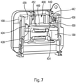
- the cartridge immobilization system 130 comprises a trigger 400, allowing in a first position, the maintenance of said cartridge in said housing, and in a second position, the introduction / extraction of said cartridge 130 relative to said housing 100 .
- the trigger 400 is in its first position.
- said trigger 400 can be actuated in translation in one direction, illustrated by an arrow marked 412 at the figure 6 , transverse, in particular orthogonal, to a direction of introduction/extraction of the cartridge, illustrated by an arrow marked 414 at the figure 6 (as well as the figure 1 ).
- Such an orientation makes it possible to have a simple and robust trigger.
- Said trigger 400 comprises, according to the invention, a bar 420 for blocking the cartridge 130 and comprises for example a tongue 422 for actuating the bar 420.
- Said tongue 422 here projects perpendicularly to the bar with which it may come of matter.
- the housing 100 comprises a front face 424, provided with an orifice 426 for inserting/extracting the cartridge 130.
- Said front face 424 is also provided with a notch 428 for the passage of the tongue 422, allowing the user to manipulate the latter from the outside, in a movement oriented along the direction 412.
- Said notch 428 may be formed in the outline of the orifice 426 for inserting/extracting the cartridge 130 or, as here, be independent.
- said front face 424 of the casing forms a facade for receiving the cartridge 130.
- Said tongue 422 may be configured to come face to face with two opposite longitudinal edges of said notch 428, with a slight play, so that said tongue 422 is guided along said longitudinal edges of the notch, thus facilitating guiding the strip 420 in its translational movement.
- Said strip 420 comprises, according to the invention, at least one stop 430, here two stops 430, for blocking the cartridge 130.
- said stops 430 are located at an outline of said strip 420, in particular along one of its edges 432, called lower, at two opposite longitudinal ends of said strip 420.
- said cartridge comprises at least one locking pin 434, here two locking pins 434, each intended to cooperate with one of said stops 430.
- said strip 420 is movable in translation along a face of the cartridge, in particular the upper face, namely the face of the cartridge at which said upper turntable 125b moves.
- Said blocking pins 434 are also located at the level of said upper face, at the level of vertices of the cartridge so as to be outside the space occupied by said upper turntable 125b, when the cartridge is in position.
- said blocking pins 434 are set back slightly from a rear face of the front 310 of the cartridge 130 so that said strip 420 is guided in its translation movement between said pins 434 and said front 310.
- Said blocking pin(s) 434 are advantageously provided with a cutaway, intended to cause actuation in translation of the strip 420 during the introduction of the cartridge 130.
- said trigger 400 may further comprise a return element, such as a spring 438, able to maintain the bar 420 in said first position in the absence of actuation of the trigger 400, that is to say, as long as the tab 422 is not moved by a user wishing to remove the cartridge 130.
- Said spring 438 bears on the housing 100, here on a side face of said housing, and on said bar 420, for example via a plate 440 provided with a guide pin 442 of the spring 438.
- Said plate 440 may come from said strip 420.
- Said guide pin 442 is advantageously oriented in the direction of translation 412 of the strip 420.
- said housing 100 may further comprise one or more studs 452 for guiding the bar 420, here from the upper face of said housing. Said bar 420 is located between said guide studs 452 and said front face of case 100.
- the immobilization system in accordance with the invention has been described in the context of a device for diffusing several fragrances, it can also be used with cartridges serving only a single fragrance. It can also be used with cartridges used for an application other than a distribution system.
Landscapes
- Health & Medical Sciences (AREA)
- Engineering & Computer Science (AREA)
- Mechanical Engineering (AREA)
- Epidemiology (AREA)
- Life Sciences & Earth Sciences (AREA)
- Animal Behavior & Ethology (AREA)
- General Health & Medical Sciences (AREA)
- Public Health (AREA)
- Veterinary Medicine (AREA)
- Disinfection, Sterilisation Or Deodorisation Of Air (AREA)
- Fittings On The Vehicle Exterior For Carrying Loads, And Devices For Holding Or Mounting Articles (AREA)
- Air-Conditioning For Vehicles (AREA)
Claims (10)
- Anordnung, umfassend ein System zur Immobilisierung einer entnehmbaren Patrone (130) in einem Gehäuse (100) und die entnehmbare Patrone (130), wobei das System einen Auslöser (400) umfasst, der in einer ersten Stellung das Halten der Patrone (130) in dem Gehäuse (100) und in einer zweiten Stellung das Einführen/Entnehmen der Patrone (130) in Bezug auf das Gehäuse ermöglicht, dadurch gekennzeichnet, dass der Auslöser (400) translatorisch entlang einer Richtung quer zu einer Einführ-/Entnahmerichtung der Patrone (130) betätigbar ist, wobei der Auslöser (400) einen Schieber (420) zum Sichern der Patrone (130) umfasst, wobei der Schieber (420) mindestens einen Anschlag (430) zum Sichern der Patrone (130) umfasst, wobei der oder die Anschläge (430) dazu bestimmt sind, mit einem oder mehreren Sicherungsstiften (434) der Patrone (130) zusammenzuwirken, wobei bei der Anordnung der oder die Sicherungsstifte (434) mit einer Schräge versehen sind, die dazu bestimmt ist, beim Einführen der Patrone (130) eine translatorische Betätigung des Schiebers (420) zu bewirken.
- Anordnung nach Anspruch 1, wobei der Auslöser (400) einen Betätigungslappen (422) des Schiebers (420) umfasst.
- Anordnung nach Anspruch 2, bei welcher der Lappen (422) dazu ausgestaltet ist, durch eine Aufnahmefront des Gehäuses (100) hindurch zu münden.
- Anordnung nach Anspruch 1, bei welcher der oder die Anschläge (430) an einer Kontur des Schiebers (420) gelegen sind.
- Anordnung nach einem der vorhergehenden Ansprüche, bei welcher der Auslöser (400) ein Rückstellelement umfasst, das geeignet ist, den Schieber (420) bei Nichtbetätigung des Auslösers in der ersten Stellung zu halten.
- Anordnung nach Anspruch 5, bei der das Rückstellelement eine Feder (438) umfasst, wobei die Feder dazu ausgestaltet ist, an dem Gehäuse (100) und an dem Schieber (420) anzuliegen.
- Anordnung nach Anspruch 6 wobei der Schieber (420) eine Platte (440) umfasst, die mit einem Finger (442) zum Führen der Feder (438) versehen ist.
- Anordnung nach einem der vorhergehenden Ansprüche, bei welcher der oder die Sicherungsstifte (434) an einer Seite, Oberseite genannt, der Patrone (130) gelegen sind.
- Anordnung nach Anspruch 8, bei welcher der Schieber (420) translatorisch entlang der Oberseite der Patrone (130) beweglich ist.
- Vorrichtung zum Verbreiten eines flüchtigen Stoffs, die eine Anordnung nach einem der Ansprüche 1 bis 9 umfasst.
Applications Claiming Priority (2)
| Application Number | Priority Date | Filing Date | Title |
|---|---|---|---|
| FR1550668A FR3032011B1 (fr) | 2015-01-28 | 2015-01-28 | Systeme d'immobilisation d'une cartouche amovible dans un boitier |
| PCT/EP2016/051106 WO2016120137A1 (fr) | 2015-01-28 | 2016-01-20 | Système d'immobilisation d'une cartouche amovible dans un boîtier |
Publications (2)
| Publication Number | Publication Date |
|---|---|
| EP3265332A1 EP3265332A1 (de) | 2018-01-10 |
| EP3265332B1 true EP3265332B1 (de) | 2022-01-19 |
Family
ID=53200090
Family Applications (1)
| Application Number | Title | Priority Date | Filing Date |
|---|---|---|---|
| EP16701130.3A Active EP3265332B1 (de) | 2015-01-28 | 2016-01-20 | System zur immobilisierung einer auswechselbaren kassette in einem gehäuse |
Country Status (6)
| Country | Link |
|---|---|
| EP (1) | EP3265332B1 (de) |
| JP (1) | JP6567676B2 (de) |
| KR (1) | KR20170116060A (de) |
| CN (1) | CN107206869B (de) |
| FR (1) | FR3032011B1 (de) |
| WO (1) | WO2016120137A1 (de) |
Families Citing this family (4)
| Publication number | Priority date | Publication date | Assignee | Title |
|---|---|---|---|---|
| FR3063681A1 (fr) * | 2017-03-08 | 2018-09-14 | Valeo Systemes Thermiques | Dispositif d'immobilisation d'une cartouche dans un boitier, boitier comprenant ledit dispositif et ensemble dudit boitier et de ladite cartouche |
| DE102020201256A1 (de) * | 2020-02-03 | 2021-08-05 | Mahle International Gmbh | Beduftungsvorrichtung |
| CZ310150B6 (cs) | 2020-04-02 | 2024-10-09 | ŠKODA AUTO a.s | Aromatizační zařízení pro provonění interiéru vozidla |
| CN116182316B (zh) * | 2021-11-29 | 2026-03-24 | 广东美的制冷设备有限公司 | 香氛模块和空调器 |
Family Cites Families (7)
| Publication number | Priority date | Publication date | Assignee | Title |
|---|---|---|---|---|
| JP2693024B2 (ja) * | 1990-08-01 | 1997-12-17 | キヤノン株式会社 | カメラ |
| JP3108171B2 (ja) * | 1991-12-11 | 2000-11-13 | 株式会社リコー | 記録装置及びカートリッジ |
| IT1279566B1 (it) * | 1995-05-26 | 1997-12-16 | Fiat Auto Spa | Dispositivo di filtrazione dell'aria per un impianto di aerazione, in particolare per un veicolo. |
| JP3416904B2 (ja) * | 1997-09-19 | 2003-06-16 | 東芝テック株式会社 | インクジェットプリンタ |
| FR2833887B1 (fr) * | 2001-12-20 | 2004-02-27 | Valeo Climatisation | Dispositif d'odorisation de l'habitacle d'un vehicule automobile |
| JP5056163B2 (ja) * | 2007-05-25 | 2012-10-24 | ブラザー工業株式会社 | インクカートリッジの判定装置及び判定方法 |
| CN101687054B (zh) * | 2007-07-03 | 2014-01-01 | 贝洱两合公司 | 用于汽车的空气清新装置 |
-
2015
- 2015-01-28 FR FR1550668A patent/FR3032011B1/fr active Active
-
2016
- 2016-01-20 JP JP2017539607A patent/JP6567676B2/ja active Active
- 2016-01-20 EP EP16701130.3A patent/EP3265332B1/de active Active
- 2016-01-20 KR KR1020177023789A patent/KR20170116060A/ko not_active Ceased
- 2016-01-20 WO PCT/EP2016/051106 patent/WO2016120137A1/fr not_active Ceased
- 2016-01-20 CN CN201680007708.7A patent/CN107206869B/zh active Active
Also Published As
| Publication number | Publication date |
|---|---|
| JP6567676B2 (ja) | 2019-08-28 |
| FR3032011B1 (fr) | 2017-08-04 |
| WO2016120137A1 (fr) | 2016-08-04 |
| EP3265332A1 (de) | 2018-01-10 |
| CN107206869A (zh) | 2017-09-26 |
| CN107206869B (zh) | 2021-02-02 |
| JP2018507021A (ja) | 2018-03-15 |
| KR20170116060A (ko) | 2017-10-18 |
| FR3032011A1 (fr) | 2016-07-29 |
Similar Documents
| Publication | Publication Date | Title |
|---|---|---|
| EP3265332B1 (de) | System zur immobilisierung einer auswechselbaren kassette in einem gehäuse | |
| EP3002142B1 (de) | Verriegelungssystem einer entfernbaren patrone in einem gehäuse | |
| EP2025544B1 (de) | Diffusionsvorrichtung für flüchtige Wirkstoffe, ausgestattet mit einem Mittel zum Entfernen von Patronen | |
| EP3200835A1 (de) | Diffusionsvorrichtung und abnehmbare kartusche für besagte vorrichtung | |
| EP3200836B1 (de) | Diffusionsvorrichtung mit zwei drehbaren platten | |
| FR2849817A1 (fr) | Retroviseur pour vehicule comportant un miroir monte pivotant sur deux axes perpendiculaires | |
| FR2833531A1 (fr) | Dispositif d'odorisation a intensite reglable, notamment pour un vehicule automobile | |
| EP2011678A1 (de) | Diffusionsvorrichtung für flüchtige Wirkstoffe, ausgestattet mit einem Gebläse für Fahrzeuge | |
| EP4255512B1 (de) | Diffusor zur befestigung an einem lüftungsgitter zur gesteuerten abgabe eines lufterfrischers | |
| FR2564394A1 (fr) | Dispositif parfumeur, notamment pour automobiles | |
| WO2018162840A1 (fr) | Dispositif d'immobilisation d'une cartouche dans un boitier, boitier comprenant ledit dispositif et ensemble dudit boitier et de ladite cartouche | |
| FR2825949A1 (fr) | Dispositif de chauffage et/ou de climatisation de l'habitacle d'un vehicule automobile comportant un dispositif d'odorisation | |
| EP2364173B1 (de) | Pulverinhalationsvorrichtung | |
| FR2833534A1 (fr) | Dispositif d'odorisation de l'habitacle d'un vehicule automobile | |
| FR3026305A1 (fr) | Dispositif de diffusion et cartouche pour ledit dispositif | |
| FR2848915A1 (fr) | Dispositif de diffusion d'au moins un parfum dans un habitacle d'un vehicule automobile. | |
| EP3302646B1 (de) | Autoinjektor mit einer verzögerungsvorrichtung mit einem planetengetriebe | |
| EP3162383A1 (de) | Vorrichtung zum verteilen mindestens eines flüchtigen mittels | |
| EP3746030A1 (de) | Vorrichtung zum dosieren oder zählen von gegenständen | |
| FR2865968A1 (fr) | Aerateur, notamment pour vehicule automobile | |
| EP1541396A1 (de) | Luftausströmer für ein Fahrzeug, insbesondere ein Kraftfahrzeug, mit einem Duftspender | |
| FR2791114A1 (fr) | Dispositif permettant de commander l'ecoulement d'un fluide et l'orientation de cet ecoulement | |
| FR3056110B1 (fr) | Boitier de stockage pour cartouche de diffuseur de produit | |
| FR2920348A1 (fr) | Cartouche amovible de diffusion d'une substance volatile dans un groupe de chauffage et/ou de climatisation de vehicule | |
| FR2918317A1 (fr) | Dispositif de diffusion d'agent volatif muni d'un bouchon pour vehicule automobile |
Legal Events
| Date | Code | Title | Description |
|---|---|---|---|
| STAA | Information on the status of an ep patent application or granted ep patent |
Free format text: STATUS: THE INTERNATIONAL PUBLICATION HAS BEEN MADE |
|
| PUAI | Public reference made under article 153(3) epc to a published international application that has entered the european phase |
Free format text: ORIGINAL CODE: 0009012 |
|
| STAA | Information on the status of an ep patent application or granted ep patent |
Free format text: STATUS: REQUEST FOR EXAMINATION WAS MADE |
|
| 17P | Request for examination filed |
Effective date: 20170818 |
|
| AK | Designated contracting states |
Kind code of ref document: A1 Designated state(s): AL AT BE BG CH CY CZ DE DK EE ES FI FR GB GR HR HU IE IS IT LI LT LU LV MC MK MT NL NO PL PT RO RS SE SI SK SM TR |
|
| AX | Request for extension of the european patent |
Extension state: BA ME |
|
| DAV | Request for validation of the european patent (deleted) | ||
| DAX | Request for extension of the european patent (deleted) | ||
| STAA | Information on the status of an ep patent application or granted ep patent |
Free format text: STATUS: EXAMINATION IS IN PROGRESS |
|
| 17Q | First examination report despatched |
Effective date: 20200723 |
|
| GRAP | Despatch of communication of intention to grant a patent |
Free format text: ORIGINAL CODE: EPIDOSNIGR1 |
|
| STAA | Information on the status of an ep patent application or granted ep patent |
Free format text: STATUS: GRANT OF PATENT IS INTENDED |
|
| INTG | Intention to grant announced |
Effective date: 20210630 |
|
| GRAJ | Information related to disapproval of communication of intention to grant by the applicant or resumption of examination proceedings by the epo deleted |
Free format text: ORIGINAL CODE: EPIDOSDIGR1 |
|
| STAA | Information on the status of an ep patent application or granted ep patent |
Free format text: STATUS: EXAMINATION IS IN PROGRESS |
|
| GRAP | Despatch of communication of intention to grant a patent |
Free format text: ORIGINAL CODE: EPIDOSNIGR1 |
|
| STAA | Information on the status of an ep patent application or granted ep patent |
Free format text: STATUS: GRANT OF PATENT IS INTENDED |
|
| INTC | Intention to grant announced (deleted) | ||
| INTG | Intention to grant announced |
Effective date: 20210927 |
|
| GRAS | Grant fee paid |
Free format text: ORIGINAL CODE: EPIDOSNIGR3 |
|
| GRAA | (expected) grant |
Free format text: ORIGINAL CODE: 0009210 |
|
| STAA | Information on the status of an ep patent application or granted ep patent |
Free format text: STATUS: THE PATENT HAS BEEN GRANTED |
|
| AK | Designated contracting states |
Kind code of ref document: B1 Designated state(s): AL AT BE BG CH CY CZ DE DK EE ES FI FR GB GR HR HU IE IS IT LI LT LU LV MC MK MT NL NO PL PT RO RS SE SI SK SM TR |
|
| REG | Reference to a national code |
Ref country code: GB Ref legal event code: FG4D Free format text: NOT ENGLISH |
|
| REG | Reference to a national code |
Ref country code: CH Ref legal event code: EP |
|
| REG | Reference to a national code |
Ref country code: AT Ref legal event code: REF Ref document number: 1463600 Country of ref document: AT Kind code of ref document: T Effective date: 20220215 |
|
| REG | Reference to a national code |
Ref country code: IE Ref legal event code: FG4D Free format text: LANGUAGE OF EP DOCUMENT: FRENCH |
|
| REG | Reference to a national code |
Ref country code: DE Ref legal event code: R096 Ref document number: 602016068449 Country of ref document: DE |
|
| REG | Reference to a national code |
Ref country code: LT Ref legal event code: MG9D |
|
| REG | Reference to a national code |
Ref country code: NL Ref legal event code: MP Effective date: 20220119 |
|
| REG | Reference to a national code |
Ref country code: AT Ref legal event code: MK05 Ref document number: 1463600 Country of ref document: AT Kind code of ref document: T Effective date: 20220119 |
|
| PG25 | Lapsed in a contracting state [announced via postgrant information from national office to epo] |
Ref country code: NL Free format text: LAPSE BECAUSE OF FAILURE TO SUBMIT A TRANSLATION OF THE DESCRIPTION OR TO PAY THE FEE WITHIN THE PRESCRIBED TIME-LIMIT Effective date: 20220119 |
|
| PG25 | Lapsed in a contracting state [announced via postgrant information from national office to epo] |
Ref country code: SE Free format text: LAPSE BECAUSE OF FAILURE TO SUBMIT A TRANSLATION OF THE DESCRIPTION OR TO PAY THE FEE WITHIN THE PRESCRIBED TIME-LIMIT Effective date: 20220119 Ref country code: RS Free format text: LAPSE BECAUSE OF FAILURE TO SUBMIT A TRANSLATION OF THE DESCRIPTION OR TO PAY THE FEE WITHIN THE PRESCRIBED TIME-LIMIT Effective date: 20220119 Ref country code: PT Free format text: LAPSE BECAUSE OF FAILURE TO SUBMIT A TRANSLATION OF THE DESCRIPTION OR TO PAY THE FEE WITHIN THE PRESCRIBED TIME-LIMIT Effective date: 20220519 Ref country code: NO Free format text: LAPSE BECAUSE OF FAILURE TO SUBMIT A TRANSLATION OF THE DESCRIPTION OR TO PAY THE FEE WITHIN THE PRESCRIBED TIME-LIMIT Effective date: 20220419 Ref country code: LT Free format text: LAPSE BECAUSE OF FAILURE TO SUBMIT A TRANSLATION OF THE DESCRIPTION OR TO PAY THE FEE WITHIN THE PRESCRIBED TIME-LIMIT Effective date: 20220119 Ref country code: HR Free format text: LAPSE BECAUSE OF FAILURE TO SUBMIT A TRANSLATION OF THE DESCRIPTION OR TO PAY THE FEE WITHIN THE PRESCRIBED TIME-LIMIT Effective date: 20220119 Ref country code: ES Free format text: LAPSE BECAUSE OF FAILURE TO SUBMIT A TRANSLATION OF THE DESCRIPTION OR TO PAY THE FEE WITHIN THE PRESCRIBED TIME-LIMIT Effective date: 20220119 Ref country code: BG Free format text: LAPSE BECAUSE OF FAILURE TO SUBMIT A TRANSLATION OF THE DESCRIPTION OR TO PAY THE FEE WITHIN THE PRESCRIBED TIME-LIMIT Effective date: 20220419 |
|
| PG25 | Lapsed in a contracting state [announced via postgrant information from national office to epo] |
Ref country code: PL Free format text: LAPSE BECAUSE OF FAILURE TO SUBMIT A TRANSLATION OF THE DESCRIPTION OR TO PAY THE FEE WITHIN THE PRESCRIBED TIME-LIMIT Effective date: 20220119 Ref country code: LV Free format text: LAPSE BECAUSE OF FAILURE TO SUBMIT A TRANSLATION OF THE DESCRIPTION OR TO PAY THE FEE WITHIN THE PRESCRIBED TIME-LIMIT Effective date: 20220119 Ref country code: GR Free format text: LAPSE BECAUSE OF FAILURE TO SUBMIT A TRANSLATION OF THE DESCRIPTION OR TO PAY THE FEE WITHIN THE PRESCRIBED TIME-LIMIT Effective date: 20220420 Ref country code: FI Free format text: LAPSE BECAUSE OF FAILURE TO SUBMIT A TRANSLATION OF THE DESCRIPTION OR TO PAY THE FEE WITHIN THE PRESCRIBED TIME-LIMIT Effective date: 20220119 Ref country code: AT Free format text: LAPSE BECAUSE OF FAILURE TO SUBMIT A TRANSLATION OF THE DESCRIPTION OR TO PAY THE FEE WITHIN THE PRESCRIBED TIME-LIMIT Effective date: 20220119 |
|
| REG | Reference to a national code |
Ref country code: CH Ref legal event code: PL |
|
| PG25 | Lapsed in a contracting state [announced via postgrant information from national office to epo] |
Ref country code: IS Free format text: LAPSE BECAUSE OF FAILURE TO SUBMIT A TRANSLATION OF THE DESCRIPTION OR TO PAY THE FEE WITHIN THE PRESCRIBED TIME-LIMIT Effective date: 20220519 |
|
| REG | Reference to a national code |
Ref country code: BE Ref legal event code: MM Effective date: 20220131 |
|
| REG | Reference to a national code |
Ref country code: DE Ref legal event code: R097 Ref document number: 602016068449 Country of ref document: DE |
|
| PG25 | Lapsed in a contracting state [announced via postgrant information from national office to epo] |
Ref country code: SM Free format text: LAPSE BECAUSE OF FAILURE TO SUBMIT A TRANSLATION OF THE DESCRIPTION OR TO PAY THE FEE WITHIN THE PRESCRIBED TIME-LIMIT Effective date: 20220119 Ref country code: SK Free format text: LAPSE BECAUSE OF FAILURE TO SUBMIT A TRANSLATION OF THE DESCRIPTION OR TO PAY THE FEE WITHIN THE PRESCRIBED TIME-LIMIT Effective date: 20220119 Ref country code: RO Free format text: LAPSE BECAUSE OF FAILURE TO SUBMIT A TRANSLATION OF THE DESCRIPTION OR TO PAY THE FEE WITHIN THE PRESCRIBED TIME-LIMIT Effective date: 20220119 Ref country code: MC Free format text: LAPSE BECAUSE OF FAILURE TO SUBMIT A TRANSLATION OF THE DESCRIPTION OR TO PAY THE FEE WITHIN THE PRESCRIBED TIME-LIMIT Effective date: 20220119 Ref country code: LU Free format text: LAPSE BECAUSE OF NON-PAYMENT OF DUE FEES Effective date: 20220120 Ref country code: EE Free format text: LAPSE BECAUSE OF FAILURE TO SUBMIT A TRANSLATION OF THE DESCRIPTION OR TO PAY THE FEE WITHIN THE PRESCRIBED TIME-LIMIT Effective date: 20220119 Ref country code: DK Free format text: LAPSE BECAUSE OF FAILURE TO SUBMIT A TRANSLATION OF THE DESCRIPTION OR TO PAY THE FEE WITHIN THE PRESCRIBED TIME-LIMIT Effective date: 20220119 Ref country code: CZ Free format text: LAPSE BECAUSE OF FAILURE TO SUBMIT A TRANSLATION OF THE DESCRIPTION OR TO PAY THE FEE WITHIN THE PRESCRIBED TIME-LIMIT Effective date: 20220119 |
|
| PLBE | No opposition filed within time limit |
Free format text: ORIGINAL CODE: 0009261 |
|
| STAA | Information on the status of an ep patent application or granted ep patent |
Free format text: STATUS: NO OPPOSITION FILED WITHIN TIME LIMIT |
|
| PG25 | Lapsed in a contracting state [announced via postgrant information from national office to epo] |
Ref country code: BE Free format text: LAPSE BECAUSE OF NON-PAYMENT OF DUE FEES Effective date: 20220131 Ref country code: AL Free format text: LAPSE BECAUSE OF FAILURE TO SUBMIT A TRANSLATION OF THE DESCRIPTION OR TO PAY THE FEE WITHIN THE PRESCRIBED TIME-LIMIT Effective date: 20220119 |
|
| 26N | No opposition filed |
Effective date: 20221020 |
|
| GBPC | Gb: european patent ceased through non-payment of renewal fee |
Effective date: 20220419 |
|
| PG25 | Lapsed in a contracting state [announced via postgrant information from national office to epo] |
Ref country code: LI Free format text: LAPSE BECAUSE OF NON-PAYMENT OF DUE FEES Effective date: 20220131 Ref country code: CH Free format text: LAPSE BECAUSE OF NON-PAYMENT OF DUE FEES Effective date: 20220131 |
|
| PG25 | Lapsed in a contracting state [announced via postgrant information from national office to epo] |
Ref country code: IE Free format text: LAPSE BECAUSE OF NON-PAYMENT OF DUE FEES Effective date: 20220120 Ref country code: GB Free format text: LAPSE BECAUSE OF NON-PAYMENT OF DUE FEES Effective date: 20220419 |
|
| PG25 | Lapsed in a contracting state [announced via postgrant information from national office to epo] |
Ref country code: SI Free format text: LAPSE BECAUSE OF FAILURE TO SUBMIT A TRANSLATION OF THE DESCRIPTION OR TO PAY THE FEE WITHIN THE PRESCRIBED TIME-LIMIT Effective date: 20220119 |
|
| P01 | Opt-out of the competence of the unified patent court (upc) registered |
Effective date: 20230528 |
|
| PG25 | Lapsed in a contracting state [announced via postgrant information from national office to epo] |
Ref country code: IT Free format text: LAPSE BECAUSE OF FAILURE TO SUBMIT A TRANSLATION OF THE DESCRIPTION OR TO PAY THE FEE WITHIN THE PRESCRIBED TIME-LIMIT Effective date: 20220119 |
|
| PG25 | Lapsed in a contracting state [announced via postgrant information from national office to epo] |
Ref country code: HU Free format text: LAPSE BECAUSE OF FAILURE TO SUBMIT A TRANSLATION OF THE DESCRIPTION OR TO PAY THE FEE WITHIN THE PRESCRIBED TIME-LIMIT; INVALID AB INITIO Effective date: 20160120 |
|
| PG25 | Lapsed in a contracting state [announced via postgrant information from national office to epo] |
Ref country code: MK Free format text: LAPSE BECAUSE OF FAILURE TO SUBMIT A TRANSLATION OF THE DESCRIPTION OR TO PAY THE FEE WITHIN THE PRESCRIBED TIME-LIMIT Effective date: 20220119 Ref country code: CY Free format text: LAPSE BECAUSE OF FAILURE TO SUBMIT A TRANSLATION OF THE DESCRIPTION OR TO PAY THE FEE WITHIN THE PRESCRIBED TIME-LIMIT Effective date: 20220119 |
|
| PG25 | Lapsed in a contracting state [announced via postgrant information from national office to epo] |
Ref country code: TR Free format text: LAPSE BECAUSE OF FAILURE TO SUBMIT A TRANSLATION OF THE DESCRIPTION OR TO PAY THE FEE WITHIN THE PRESCRIBED TIME-LIMIT Effective date: 20220119 |
|
| PG25 | Lapsed in a contracting state [announced via postgrant information from national office to epo] |
Ref country code: MT Free format text: LAPSE BECAUSE OF FAILURE TO SUBMIT A TRANSLATION OF THE DESCRIPTION OR TO PAY THE FEE WITHIN THE PRESCRIBED TIME-LIMIT Effective date: 20220119 |
|
| PGFP | Annual fee paid to national office [announced via postgrant information from national office to epo] |
Ref country code: DE Payment date: 20260114 Year of fee payment: 11 |
|
| PGFP | Annual fee paid to national office [announced via postgrant information from national office to epo] |
Ref country code: FR Payment date: 20260128 Year of fee payment: 11 |