EP3265342B1 - Anhängersystem für fahrzeug - Google Patents
Anhängersystem für fahrzeug Download PDFInfo
- Publication number
- EP3265342B1 EP3265342B1 EP16759545.3A EP16759545A EP3265342B1 EP 3265342 B1 EP3265342 B1 EP 3265342B1 EP 16759545 A EP16759545 A EP 16759545A EP 3265342 B1 EP3265342 B1 EP 3265342B1
- Authority
- EP
- European Patent Office
- Prior art keywords
- trailer
- carriage
- vehicle
- hitch
- cargo container
- Prior art date
- Legal status (The legal status is an assumption and is not a legal conclusion. Google has not performed a legal analysis and makes no representation as to the accuracy of the status listed.)
- Active
Links
Images







Classifications
-
- B—PERFORMING OPERATIONS; TRANSPORTING
- B60—VEHICLES IN GENERAL
- B60P—VEHICLES ADAPTED FOR LOAD TRANSPORTATION OR TO TRANSPORT, TO CARRY, OR TO COMPRISE SPECIAL LOADS OR OBJECTS
- B60P1/00—Vehicles predominantly for transporting loads and modified to facilitate loading, consolidating the load, or unloading
- B60P1/43—Vehicles predominantly for transporting loads and modified to facilitate loading, consolidating the load, or unloading using a loading ramp mounted on the vehicle
- B60P1/433—Vehicles predominantly for transporting loads and modified to facilitate loading, consolidating the load, or unloading using a loading ramp mounted on the vehicle the loading floor or a part thereof being movable to form the ramp
-
- B—PERFORMING OPERATIONS; TRANSPORTING
- B60—VEHICLES IN GENERAL
- B60P—VEHICLES ADAPTED FOR LOAD TRANSPORTATION OR TO TRANSPORT, TO CARRY, OR TO COMPRISE SPECIAL LOADS OR OBJECTS
- B60P1/00—Vehicles predominantly for transporting loads and modified to facilitate loading, consolidating the load, or unloading
- B60P1/48—Vehicles predominantly for transporting loads and modified to facilitate loading, consolidating the load, or unloading using pivoted arms raisable above load-transporting element
- B60P1/483—Vehicles predominantly for transporting loads and modified to facilitate loading, consolidating the load, or unloading using pivoted arms raisable above load-transporting element using pivoted arms shifting the load-transporting element in a fore or aft direction
-
- B—PERFORMING OPERATIONS; TRANSPORTING
- B60—VEHICLES IN GENERAL
- B60P—VEHICLES ADAPTED FOR LOAD TRANSPORTATION OR TO TRANSPORT, TO CARRY, OR TO COMPRISE SPECIAL LOADS OR OBJECTS
- B60P1/00—Vehicles predominantly for transporting loads and modified to facilitate loading, consolidating the load, or unloading
- B60P1/64—Vehicles predominantly for transporting loads and modified to facilitate loading, consolidating the load, or unloading the load supporting or containing element being readily removable
- B60P1/6418—Vehicles predominantly for transporting loads and modified to facilitate loading, consolidating the load, or unloading the load supporting or containing element being readily removable the load-transporting element being a container or similar
- B60P1/6427—Vehicles predominantly for transporting loads and modified to facilitate loading, consolidating the load, or unloading the load supporting or containing element being readily removable the load-transporting element being a container or similar the load-transporting element being shifted horizontally in a fore and aft direction, combined or not with a vertical displacement
-
- B—PERFORMING OPERATIONS; TRANSPORTING
- B60—VEHICLES IN GENERAL
- B60P—VEHICLES ADAPTED FOR LOAD TRANSPORTATION OR TO TRANSPORT, TO CARRY, OR TO COMPRISE SPECIAL LOADS OR OBJECTS
- B60P1/00—Vehicles predominantly for transporting loads and modified to facilitate loading, consolidating the load, or unloading
- B60P1/64—Vehicles predominantly for transporting loads and modified to facilitate loading, consolidating the load, or unloading the load supporting or containing element being readily removable
- B60P1/6418—Vehicles predominantly for transporting loads and modified to facilitate loading, consolidating the load, or unloading the load supporting or containing element being readily removable the load-transporting element being a container or similar
- B60P1/6454—Vehicles predominantly for transporting loads and modified to facilitate loading, consolidating the load, or unloading the load supporting or containing element being readily removable the load-transporting element being a container or similar the load transporting element being shifted by means of an inclined ramp connected to the vehicle
Definitions
- the present invention relates generally to trailers, and more particularly, to a vehicle trailer system including a movable, preferably pivotable arm and winding cable for lifting a load, and a translational carriage including a load hitch for coupling the load thereon.
- the vehicle trailer system is suitable for loading, transporting and unloading a load such as a cargo container and facilitates ease in loading the cargo container onto a trailer.
- Cargo containers such as intermodal containers, freight containers, ISO containers, shipping containers, hi-cube containers or the like, are generally metallic structures vastly used to transport items or materials over land via roadways or railways or via sea transportation.
- cargo containers may be used to transport equipment or shelters for various military operations.
- cargo containers may be used to transport a variety of different types of equipment or materials.
- Cargo containers can also be used to temporarily or permanently store objects.
- Containers typically include a floor, walls extending from the floor and a roof on the walls. One or more doors may be provided in the walls of the containers.
- Containers can also typically include fasteners, or fastening portions to which fasteners can be coupled, to allow securing the containers during loading, unloading and
- ISO containers include eight ISO connectors, one at each corner of the container, for attaching ISO compliant fasteners.
- Loading and unloading of cargo containers onto or from ships, trains or other means of transportation or storage can be carried out by various means.
- vertically lifting cranes can be used to load and unload containers in large vessels or freights.
- reach stackers can be used for stacking a reduced number of containers, such as onto a train.
- Vehicle trailer systems are known in the art comprising a tiltable trailer bed and a winch capable of dragging the container onto the trailer bed.
- a front side of the container is initially lifted from the ground by inserting a wedge underneath the container front end (by pure force).
- the container is then dragged onto a tilted trailer bed which is coupled to a towing vehicle.
- the trailer is tilted to a generally horizontal transport position for transport of the container to the desired destination.
- a vehicle trailer system which is suitable for loading, transporting and unloading a load such as a cargo container, which allows for simple and effective loading, transportation and unloading of a cargo container on and from a trailer without damaging the container or its contents, and is thus valid for transporting virtually any kind of cargo including fragile items.
- FR2156988 discloses: A vehicle trailer system for loading, transporting and unloading a load, the vehicle trailer system comprising:
- the present invention is directed to a vehicle trailer system which is suitable for loading, transporting and unloading a load such as a cargo container and which facilitates ease in loading and unloading a cargo container onto and from a trailer, allowing cargo containers to be loaded, transported and stored by smaller trailers in comparison to prior art, and thus boosting the use of cargo containers for a myriad of civil and military applications such as providing temporary housing during disaster relief.
- the vehicle trailer system includes a trailer structure which can be coupled to a towing vehicle such as a pickup truck.
- the trailer structure can include a trailer front structure and a trailer rear structure attached to the trailer front structure.
- the trailer rear structure can include a pivotable structure that is pivotably attached to the trailer front structure and supported by wheels.
- the trailer structure includes a longitudinally-traveling carriage or trolley including a preferably ball-shaped, carriage hitch.
- a winch cable can be extended or unwound from a winch that can be mounted on the front structure of the vehicle trailer system or on the towing vehicle and that is connected to the load as the load rests on the ground behind the trailer.
- a movable, preferably pivotable arm can dispose the cable in a first suspended position in which the cable can be attached to the load and pull and lift the load. The movable arm can then be moved to dispose the cable in a second position with a strong vertical component for the cable to lower the load onto the carriage hitch and couple the load to the carriage. The movable arm can then be operated to pivot away from the cable and fold into the trailer structure. Subsequent operating of the winch causes the cargo container to be pulled onto the trailer by the carriage, until the cargo container is fully supported by the trailer.
- a vehicle trailer system for loading, transporting and unloading a load includes a trailer, arranged along a front-to-back, longitudinal direction, the trailer comprising a wheeled trailer structure for attachment to a towing vehicle.
- the trailer further includes a carriage mounted for bidirectional travel on the trailer structure along the longitudinal direction.
- a carriage hitch is carried by the carriage, the carriage hitch being configured for coupling to a load.
- a movable arm is carried by the trailer structure.
- An arm actuator is carried by the trailer structure and operably engages the movable arm to selectively position the movable arm in a lowered position in which the carriage can travel over the movable arm, and in a plurality of raised positions in which the movable arm extends above the carriage.
- a flexible, windable elongated element e.g., a cable
- the movable arm can be pivotable about a side-to-side, transverse rotation axis and along a vertical longitudinal plane which is longitudinally aligned with the carriage hitch.
- the wheeled trailer structure can include a trailer front structure for attachment to the towing vehicle, and a trailer rear structure, pivotably attached to the trailer front structure about a side-to-side, transverse pivot axis.
- the movable arm is preferably pivotably carried by the trailer rear structure.
- the trailer rear structure can include a pivotable structure pivotably attached to the trailer front structure and supported on the ground by at least one pair of wheels.
- the pivotable structure of the trailer rear structure can include a pair of spaced-apart trailer rails and the carriage can be translationally mounted on the trailer rails.
- the carriage can be arranged between the trailer rails.
- the carriage hitch can include a hitch ball providing a ball-joint coupling with the load.
- the ball-joint coupling can be arranged vertically higher than adjacent portions of the trailer structure to facilitate rotation of the load relative to the trailer structure about the ball-joint coupling.
- the vehicle trailer system can further include at least one roller attachable to the load.
- the vehicle trailer system can also include a hitch structure removably attachable to the load, the hitch structure comprising a hitch coupler for engaging with the carriage hitch, and a fastener for coupling the fastener of the flexible, windable elongated element.
- the movable arm can further include a retainer transversely retaining the flexible, windable elongated element within the movable arm when the flexible, windable elongated element is supported by the movable arm.
- the movable arm can include at least one pulley from which the flexible, windable elongated element is suspended in at least one of the plurality of raised positions.
- the trailer structure can further include at least one trailer roller arranged at a rear end of the trailer structure.
- the trailer roller or rollers are rotatable about a side-to-side, transverse rotational axis for the longitudinal rolling thereon of the load.
- the trailer structure can include two trailer rollers, one on each opposite side of a rear end of the trailer structure.
- the vehicle trailer system can further include at least one user-operable control for operating the arm actuator.
- the vehicle trailer system can further include a winch for winding and unwinding the flexible, winding elongated element, and at least one user-operable control for operating the winch.
- the present invention is directed toward a vehicle trailer system which is suitable for loading, transporting and unloading a load such as a cargo container and which facilitates ease in loading a cargo container onto a trailer.
- a vehicle trailer system in accordance with the invention requires a minimal trailer length for loading and unloading the container.
- the trailer system may present a relatively small length in comparison to container-transporting trailer systems known currently in the art in which the container is dragged onto a tilted trailer bed.
- the vehicle trailer system of the present invention can present a reduced weight and thus permit the container to carry an increased load.
- the vehicle trailer system of the present invention minimizes friction between the trailer and the container while loading and unloading the container, thus minimizing the force and power required to pull the container and providing an extremely smooth and non-jerky loading of the container.
- the pulling mechanism or winch carried by the trailer or truck will be required to exert a minimal force and power in comparison to conventional container-dragging vehicle trailer systems.
- the vehicle trailer system of the present invention will permit cargo containers to be able to be towed by a greater variety of vehicles, which will ultimately allow containers to become widely utilized as their loading, transportation and unloading will not necessarily have to be driven by larger and more costly vehicles such as semi-trailer trucks of the kind that do not include a forklift crane.
- the vehicle trailer system 100 includes a trailer 110 for supporting and transporting cargo, such as but not limited to a cargo container 400 such as that of FIG. 2 .
- the trailer 110 is generally elongated along a length-wise, front-to-back or longitudinal direction 102, and comprises a trailer front structure 120 for attachment to a towing vehicle, and a trailer rear structure 140 which is pivoted to the trailer front structure 120, as will be explained hereinafter.
- a widthwise, side-to-side or transverse direction 104 is further defined, as shown in FIG.
- the trailer front structure 120 of the present embodiment is configured to be coupled to a towing vehicle (not illustrated).
- the trailer front structure 120 may include a pair of side frame members 122 and at least one frame brace 124 to form a rigid structure.
- a trailer hitch coupler 126 may be provided on the trailer front structure 120 to facilitate coupling of the trailer front structure 120 to a companion hitch (not illustrated) on the towing vehicle, such as but not limited to a ball-type hitch.
- the attachment between the trailer hitch coupler 126 and the companion hitch on the vehicle may facilitate pivoting of the trailer front structure 120 in a horizontal plane (i.e. about a vertical rotation axis 128) with respect to the towing vehicle.
- the trailer rear structure 140 comprises at least one pair of trailer wheels 142 and a pivotable structure 150 which is supported on the ground by the at least one pair of trailer wheels 142.
- the trailer rear structure 140 may further include a suspension system 144 ( FIG. 1 ) which provides relative vertical movement between the trailer wheels 142 and the pivotable structure 150.
- the suspension system 144 can provide a relative transverse movement between the pivotable structure 150 and the trailer wheels 142.
- the pivotable structure 150 of the trailer rear structure 140 of the present embodiment may include a pair of generally elongated trailer rails 152, arranged along the longitudinal direction 102, parallel and spaced-apart with respect to each other. At least one frame brace 154 may connect the trailer rails 152 to form a rigid structure.
- the frame braces 154 of the present embodiment are arranged transversely, i.e., perpendicular to the longitudinal trailer rails 152.
- the pivotable structure 150 of the trailer rear structure 140 of the present embodiment is pivotably attached to the trailer front structure 120 by having the trailer rails 152 pivotally attached to a respective side frame member 122 of the trailer front structure 120.
- each trailer rail 152 and the respective side frame member 122 of the trailer front structure 120 is provided by a respective pivot pin 130.
- the articulated connections or pivot pins 130 define a pivot axis 132, which in the present embodiment is arranged in the transverse direction 104. Accordingly, the pivotable structure 150 of the trailer rear structure 140 may be selectively pivoted vertically upward and downward with respect to the trailer front structure 120.
- a pair of trailer rollers 160 may be provided on the trailer 110, and particularly on the rear end of the pivotable structure 150 of the trailer rear structure 140.
- the trailer rollers 160 may be mounted for rotation on a pair of roller mount members 162, respectively, which extend outwardly from the respective trailer rails 152 generally at or adjacent to the rear end of the trailer 110.
- the pair of roller mount members 162 of the present embodiment are provided by opposite ends of a rear crossbeam 164, which extends across the pivotable structure 150.
- the roller mount members 162 can be integrally formed with or affixed to an outer surface of each trailer rail 152. The purpose of the trailer rollers 160 will be hereinafter described.
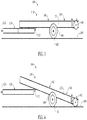
- FIGS. 3 and 4 present the trailer rear structure 140, and particularly the pivotable structure 150 of the trailer rear structure 140, in two different pivotal positions in relation to the trailer front structure 120.
- a first pivotal position shown in FIG. 3
- the pivotable structure 150 of the trailer rear structure 140 is pivoted upward about the pivot axis 132, and the trailer rails 152 are arranged in a generally horizontal position, while the trailer wheels 142 are supported on the ground 300.
- the trailer rollers 160 are elevated and not in contact with the ground 300.
- a second pivotal position shown in FIG.
- the pivotable structure 150 of the trailer rear structure 140 is pivoted downward or clockwise about the pivot axis 132, and the trailer rails 152 are arranged in an oblique direction, while the trailer wheels 142 continue to be supported on the ground 300.
- the trailer rollers 160 have come into contact with and rest on the ground 300.
- the trailer front structure 120 can adjust its vertical position when the pivotable structure 150 transitions between the first pivotal position and the second pivotal position, such as by having the trailer hitch coupler 126 vertically re-adjustable while the trailer front structure 120 remains horizontal, for instance as shown in FIGS. 3 and 4 of the present embodiment.
- the trailer front structure 120 can adjust its angle relative to the ground 300, and become tilted upwardly towards the pivot axis 132 when the trailer rear structure 140 is in the tilted position of FIG. 4 .
- the suspension system 144 of the trailer wheels 142 can allow for a relative vertical displacement of the pivotable structure 150 with respect to the trailer wheels 142.
- a movable arm 180 may be pivotally mounted on the trailer 110, and particularly, to the pivotable structure 150 of the trailer rear structure 140.
- the pivotable structure 150 includes an arm mount member 166, which may extend between the trailer rails 152 at a rear end of the trailer rear structure 140, the movable arm 180 being affixed to and supported by the arm mount member 166.
- a pair of spaced-apart arm mount flanges 168 may extend forwardly from the arm mount member 166.
- the movable arm 180 may be pivotally mounted between the arm mount flanges 168 via an arm pivot point 182.
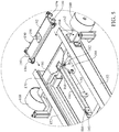
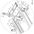
- the movable arm 180 may be pivotal between a lowered position such as that of FIG. 5 and a raised position such as that of FIG. 6 , for purposes which will be hereinafter described.
- a pulley 184 and retainer 185 may be provided at the end of the movable arm 180; the retainer 185 can be a substantially U-shaped channel as shown in the drawings, or the like, for allowing a cable, chain, rope, cord or other flexible, windable elongated element (hereinafter referred to generally as cable) to slide therethrough and on the pulley 184 while transversely retaining the cable therein.
- a pneumatic, hydraulic or electric arm actuating cylinder 186 may be pivotally attached to the pivotable structure 150 and the movable arm 180; for instance, the arm actuating cylinder 186 of the present embodiment is pivotably attached to the arm mount flanges 168 of the pivotable structure 150 and to the movable arm 180.
- the arm actuating cylinder 186 can be operated to extend, retract and pivot by appropriate user operation of user-operable cylinder controls, which may be arranged on a wired or wireless console (not shown) in communication with the trailer 110 as known in the art.
- the arm actuating cylinder 186 may be selectively operable to pivot the movable arm 180 at the arm pivot point 182 and deploy the movable arm 180 in the lower position illustrated in FIG. 5 or in the raised position illustrated in FIG. 6 responsive to retraction and extension, respectively, of the arm actuating cylinder 186.
- a carriage 190 is mounted for bidirectional travel on the trailer 110.
- the pivotable structure 150 of the trailer rear structure 140 of the present embodiment includes a pair of carriage roller channels, tracks or grooves 170 be provided in the respective trailer rails 152 of the pivotable structure 150 in facing relationship to each other.
- the carriage 190 comprises a carriage body 192, which can be generally planar and rectangular. At least one carriage roller 1 94 may be provided on each end of the carriage 190, rotatably attached to the carriage body 192. Each carriage roller 194 may be sized and configured for insertion into the carriage roller groove 170 in the trailer rail 152 on the corresponding side of the pivotable structure 150 of the trailer rear structure 140.
- a carriage hitch 196 may be provided on the carriage 190 for purposes which will be hereinafter described. Preferably, the carriage hitch 196 is in longitudinally registration or alignment with the pivotable arm 180, as shown in the drawings.
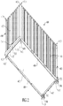
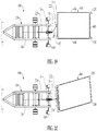
- FIG. 2 presents a cargo container 400 as known in the art, which has been configured to be loaded onto the trailer 110 in accordance with the present invention.
- the cargo container 400 may include a cargo container floor 402. Multiple cargo container walls, such as two longitudinally opposed cargo container end walls 403 and two transversely opposed, cargo container side walls 404 may extend upwardly from the cargo container floor 402.
- a cargo container ceiling 406 ( FIGS. 7-18 ) may be provided above the walls 403, 404.
- the walls 403, 404 include respective bottom edges or sides 407, 408 designed to support the cargo container 400 when left on the ground, in typical applications of the cargo container 400.
- the cargo container 400 may have at least one cargo container door (not illustrated) which facilitates loading and unloading of cargo (not illustrated) into and out of the cargo container 400.
- cargo container door (not illustrated) which facilitates loading and unloading of cargo (not illustrated) into and out of the cargo container 400.
- cargo container 400 shown in FIG. 2 is known as an ISO container and includes eight ISO connectors 410, one at each respective corner of the cargo container 400.
- an ISO connector is a standardized container corner block, including an interior corner cavity and three contiguous access openings 412 that permit the attachment of fasteners for securing loading straps, chains or cables when loading and unloading containers, or fastening straps, chains or cables when securing containers for safe transportation, to name a few applications.
- the vehicle trailer system 100 can further include a pair of cargo container rollers 200 that are attachable to a bottom rear end of the cargo container 400.
- each cargo container roller 200 of the present embodiment is rotatably supported by a roller structure 202, which is in turn securable to a bottom ISO connector 410 of the cargo container 400 by a nut and bolt (not shown).
- the illustration of FIG. 2 shows the exemplary pair of cargo container rollers 200 attached to the cargo container 400.
- the vehicle trailer system 100 can also include a cargo container hitch coupler 210 that is attachable to a bottom front end of the cargo container 400.
- the cargo container hitch coupler 210 is a cavity or recess that is provided on a bottom side of a hitch structure 212 in the shape of an elongated beam.
- the recessed cargo container hitch coupler 210 is arranged substantially at the center of the hitch structure 212.
- the hitch structure 212 is in turn securable to opposed bottom front ISO connectors 410 of the cargo container 400 by the connection of a respective nut and bolt fastener or the like (not shown) to the front opening 412 of each opposite bottom front ISO connector 410.
- the illustration of FIG. 2 shows the exemplary hitch structure 212 and cargo container hitch coupler 210 attached to the cargo container 400.
- the cargo container hitch coupler 210 is configured for coupling to the carriage hitch 196 on the carriage 190.
- the cargo container hitch coupler 210 may include a fastener 214 (e.g., a ring) that is welded or otherwise attached to the hitch structure 212; in other embodiments, the cargo container hitch coupler 210 may include any other type of mechanical component to which a hook, a self-closing hook, or the like can be coupled.
- the fastener 214 of the present embodiment is arranged also at the center of the hitch structure 212, in longitudinal registration with the cargo container hitch coupler 210 if the cargo container 400 is observed in top plan view.
- the fastener 214 and the hitch structure 212 can also be arranged substantially in vertical registration, such as in the present embodiment.
- the carriage hitch 196 on the carriage 190 may include a hitch ball to facilitate a ball joint connection between the carriage 190 and the hitch structure 212 that allows pivoting of the cargo container hitch structure 212 ( FIG. 2 ) affixed to the cargo container 400 within a horizontal plane.
- the ball-joint connection between the carnage hitch 196 permits the cargo container 400 to rotate horizontally with respect to the carnage 190, and therefore, be able to facilitate loading of the cargo container 400 onto the trailer 110 in the event that the cargo container hitch coupler 210 is not initially precisely aligned with the carriage hitch 196.
- the ball joint connection is arranged higher than adjacent portions of the trailer rails 152 so that the cargo container 400 does not rest on the trailer rails 152 when coupled to the ball joint connection, thus allowing the cargo container 400 to rotate horizontally without the trailer rails 152 frictionally interfering with the rotation.
- the ball-joint connection between the carriage hitch 196 and the cargo container hitch coupler 210 may allow the container hitch structure 212 and the cargo container 400 to slightly pivot vertically, i.e., may present a vertical tolerance which renders the joint between the trailer 110 and the cargo container 400 more resistant, durable and versatile.
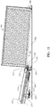
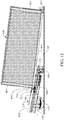
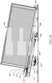
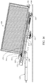
- FIGS. 7-15 present a typical application of the vehicle trailer system 100, and more particularly, a sequence of steps for loading a cargo container 400 onto the trailer 110 of the vehicle trailer system 100.
- the trailer front structure 120 of the trailer 110 is coupled to a towing vehicle (not illustrated) via the trailer hitch coupler 126.
- the trailer 110 is brought near the cargo container 400 and the pivotable structure 150 is operated to rotate in a downward direction so that the pivotable structure 150 becomes oriented in the rearwardly-sloped or angled loading position illustrated in FIG. 4 , with the trailer rollers 160 resting on the ground 300.
- the cargo container 400 rests on the ground 300 behind the trailer 110.
- a winch cable 220 is initially unwound and extended from a winch (not illustrated).
- winch cable 220 is used generally to refer to any flexible, windable elongated element capable of being wound on a winch and pulling the required load weight; for instance and without limitation, the term winch cable can include a metallic cable, a wire, a chain, a cord, or the like.
- the winch can be provided on the trailer front structure 120; in other embodiments, the winch can be provided on the towing vehicle.
- the winch can be operated to rotate in a winding direction or an unwinding direction, and stopped by appropriate user operation of user-operable winch controls, which may be arranged in the same console as the user-operable cylinder controls for operating the arm actuating cylinder 186.
- the arm actuating cylinder 186 is actuated to raise the movable arm 180 from the lowered position ( FIG. 5 ) to the raised position ( FIG. 6 ) until the movable arm 180 angles slightly rearwardly (with respect to a vertical orientation) toward the cargo container 400.
- the winch cable 220 is then extended over and onto the pulley 184 on the movable arm 180, and a hook 222 at the end of the winch cable 220 is attached to the fastener 214 on the hitch structure 212 as the cargo container 400 initially rests flat on the ground 300.
- the winch cable 220 may have been extended, and the hook 222 attached to the fastener 214, prior to raising the movable arm 180; if so, the raising movable arm 180 eventually engages with the winch cable 220 and equally reaches the position of FIGS. 7 and 16 .
- the winch (not illustrated) is then operated to wind the winch cable 220 typically in the conventional manner. Pulled by the winch, the winch cable 220 rides on the pulley 184 on the movable arm 180 and lifts the front end of the cargo container 400 from the ground 300.
- FIG. 19 shows an initial situation similar to that of FIGS. 7 and 16 , but slightly different in that the cargo container 400 is not initially aligned with the vehicle trailer system 100, but rather offset from a central vertical longitudinal plane 156 of the vehicle trailer system 100 and more particularly of the pivotable assembly 150 (the movable arm 180 and pulley 184 being on this central vertical longitudinal plane 156).
- the unaligned, suspended front end of the cargo container 400 will tend to rotate towards the central vertical longitudinal plane 156 due to gravity and assisted by the rear cargo container rollers 200.
- the winch and continued exertion of the transverse force causes the front end of the cargo container 400 to continue rotating towards the pulley 184 while the rear end can adjust its position by rolling on the cargo container rollers 200.
- the cargo container 400 reaches a position in which the fastener 214, and thus the front end of the cargo container 400, has self-aligned with the movable arm 180 as reflected in FIG. 20 .
- the front lifting of the cargo container 400 from a winch cable 220 or other flexible elongated item (e.g., a chain) combined with one or more rear bottom rollers attached to the cargo container 400 provide an automatic alignment correction of the cargo container 400 when lifted.
- operation of the winch once the front end of the cargo container 400 has been lifted from the ground 300 causes the cargo container 400 to move forward towards the trailer 110 by means of the cargo container rollers 200, while the front end of the cargo container 400 is moved upward by the winch cable 220 pulling the fastener 214.
- the shortening winch cable 220 continues to pull the cargo container 400 toward the trailer 110 as the cargo container rollers 200 roll on the ground 300.
- the cargo container hitch coupler 210 on the cargo container 400 eventually becomes disposed above and in vertical alignment with the carriage hitch 196 on the carriage 190.
- the movable arm 180 is deployed in a vertical or approximately vertical position for more robustly supporting the load. From this vertical position, the winch may be operated to slightly lengthen the winch cable 220 such that the front end of the cargo container 400 drops and the cargo container hitch coupler 210 receives the underlying carriage hitch 196 to couple the cargo container 400 to the carriage 190, as illustrated in FIG. 9 and in the matching perspective view of FIG. 17 .
- the arm actuating cylinder 186 is operated as shown in FIG.
- the winch causes the winding winch cable 220 to progressively pull the cargo container 400 up the trailer rear structure 140 and cause the carriage 190 to travel forwardly in the carriage roller grooves 170 arranged on the inner facing sides of the trailer rails 152.
- the movable arm 180 in the lowered position is arranged below the carriage 190, permitting the carriage 190 to pass over the lowered movable arm 180.
- the upward and forward moving cargo container 400 is supported on the cargo container rollers 200 and on the carriage hitch 196 (and thus on the carriage 190). Since the carriage hitch 196 provides an articulated connection of the cargo container 400 about a vertical axis, the container can gradually align with the winch cable 220 and carriage high 196 as it is pulled upward.
- continued operation of the winch eventually causes the bottom sides 408 of the cargo container side walls 404 to contact the trailer rollers 160.
- the cargo container 400 is being supported on the cargo container rollers 200, the carriage hitch 196 and the trailer rollers 160.
- continued operation of the winch causes the cargo container rollers 200 to lift off the ground 300, and the cargo container 400 to be loaded onto the pivotable structure 150 of the trailer rear structure 140 while supported on the trailer rollers 160 and the carriage hitch 196.
- FIG. 15 Further operation of the winch brings the cargo container 400 to a final position shown in FIG. 15 .
- the trailer 110 has adopted the transport position of FIG. 3 .
- the trailer rollers 160 are at a topmost raised position.
- the carriage 190 has rolled along the downward section 172 of the carriage roller grooves 170 to a final position in which the carriage 190 is sufficiently displaced downward to allow the front bottom side 407 of the cargo container 400 to rest on the trailer rails 152.
- the cargo container 400 is supported by the trailer rails 152 and the trailer rollers 160.
- the cargo container 400 In this final or fully-loaded position, the cargo container 400 is securely supported by the trailer 110 and can be transported by the towing vehicle and the vehicle trailer system 100.
- Unloading of the cargo container 400 can be easily carried out by operating the pivotable structure 150 to pivot rearward, toward the loading position of FIG. 4 .
- the pivotable structure 150 acquires a slight but sufficient tilt
- the carriage 190 cargo container 400 begins to roll rearward due to gravity.
- the winch and winch cable 220 retain the cargo container 400 so that it slowly, controlledly and safely descends along the pivotable structure 150, following a sequence that is generally reverse to the loading sequence described heretofore.
- the vehicle trailer system 100 replaces an entire container-dragging process, as taught in prior art, with a container-lifting and loading process in which the cargo container 400 is initially vertically lifted and coupled to the trailer 110 (to the carriage hitch 196) in an initial semi-loaded position ( FIG. 9 ), thereby reducing the length of the trailer 110 needed to achieve this initial semi-loaded position in comparison to container-dragging trailers known in the art.
- the cargo container 400 first lifted and then coupled while supported by the rear cargo container rollers 200 and the carriage hitch 196 ( FIGS. 9 to 13 ), and then supported by the trailer rollers 160 and the carriage hitch 196 ( FIGS. 13-14 ), and only finally supported by flat, upper surfaces of the trailer rails 152 ( FIG. 15 ), loading of the cargo container 400 onto the trailer 110 is carried out with minimum friction between the cargo container 400 and the trailer 110 in comparison to conventional trailers in which the cargo container is dragged onto a trailer bed.
- vehicle trailer system 100 described heretofore is such that the cargo container 400 in its final, loaded position rests on the trailer rails 152, alternative embodiments are contemplated in which the cargo container 400 may not rest on trailer rails.
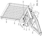
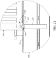
- a vehicle trailer system 500 in accordance with a second exemplary embodiment of the invention is depicted in FIGS. 21 and 22 .
- the vehicle trailer system 500 comprises a trailer front structure 520 for attachment to a towing vehicle, a wheeled trailer rear structure 540 carried by the trailer front structure 520, the trailer rear structure 540 comprising a pivotable structure 550 pivotably attached to the trailer front structure 520 and supported on the ground by at least one pair of trailer wheels (not shown, but can be the same as those included in the first exemplary embodiment).
- a carriage 590 is mounted for bidirectional travel on the pivotable structure 550, and a carriage hitch 596 is carried by the carriage 590, the carriage hitch 596 being configured for coupling to the load (e.g., cargo container 400).
- a movable arm (not shown, but for instance identical to that of the previous embodiment) is pivotally carried by the trailer rear structure 540, the movable arm being operable to selectively position the movable arm in a lowered position in which the carriage 590 can travel over the movable arm, and in raised positions in which the movable arm is elevated over the carriage 590.
- the pivotable structure 550 comprises two trailer rails 552 including a respective carriage roller groove 570.
- the carriage roller grooves 570 of the present embodiment are parallel to an upper surface 553 of the trailer rails 552 and do not end in a downward section.
- the present embodiment includes two opposed side wings 557 ending in top end connectors 558.
- the top end connectors 558 are configured to engage into a bottom opening of a corner connector of a cargo container, such as into each bottom front opening 412 of the front ISO connectors 410 of the cargo container 400 of FIG. 2 .
- the side wings 557 are attached to, and protrude outwardly from, the trailer front structure 520, and in particular from two opposed side frame members 522 of the trailer front structure 520.
- Each top end connector 558 comprises an upward-facing, preferably horizontal shoulder surface 559.
- the shoulder surfaces 559 are arranged slightly above the upper surfaces 553 of the trailer rails 552, and the cargo container 400 therefore does not rest on the upper surfaces 553 of the trailer rails 552 but on the shoulder surfaces 559.
- the cargo container 400 reaches a final, transport position in which it is supported on its front bottom ISO connectors 410, and longitudinally and transversely locked in place by, the male-female coupling of the top end connectors 558 and the respective front bottom ISO connectors 410. Coupling of the front bottom ISO connectors 410 to the top end connectors 558 of the vehicle trailer system secures the cargo container 400 longitudinally and contributes to safety during transportation.
Landscapes
- Engineering & Computer Science (AREA)
- Transportation (AREA)
- Mechanical Engineering (AREA)
- Body Structure For Vehicles (AREA)
- Handcart (AREA)
Claims (15)
- Fahrzeuganhängersystem (100) zum Laden, Transportieren und Entladen einer Last, wobei das Fahrzeuganhängersystem (100) aufweist:
einen Anhänger (110), der entlang einer vorne-nach-hinten Längsrichtung angeordnet ist, wobei der Anhänger (110) aufweist:eine beräderte Anhängerstruktur zum Anbringen an einem Zugfahrzeug;einen Schlitten (190), der zur bidirektionalen Bewegung an der Anhängerstruktur entlang der Längsrichtung angeordnet ist;eine von dem Schlitten (190) getragene Schlittenkupplung (196), wobei die Schlittenkupplung (196) zum Ankoppeln an eine Last konfiguriert ist;einen beweglichen Arm (180), der von der Anhängerstruktur getragen wird;einen Armaktuator, der von der Anhängerstruktur getragen wird und den beweglichen Arm (180) operativ in Eingriff nimmt, um den beweglichen Arm (180) wahlweise in einer abgesenkten Position, in der der Schlitten (190) über den beweglichen Arm fahren kann, und in einer Mehrzahl von angehobenen Positionen zu positionieren, in denen sich der bewegliche Arm (180) über den Schlitten (190) erstreckt; undein flexibles, wickelbares längliches Element, das von dem Armaktuator in mindestens einer der angehobenen Positionen getragen wird, wobei das flexible, wickelbare längliche Element ein Befestigungselement (214) zum Koppeln an und zum Ziehen der Last aufweist. - Fahrzeuganhänger nach Anspruch 1, bei dem der bewegliche Arm (180) um eine Seite-zu-Seite Querrotationsachse und entlang einer vertikalen Längsebene, die in Längsrichtung mit der Schlittenkupplung (196) ausgerichtet ist, schwenkbar ist.
- Fahrzeuganhänger nach Anspruch 1, bei dem die beräderte Anhängerstruktur aufweist:eine Anhängerfrontstruktur (120) zum Anbringen an dem Zugfahrzeug;eine hintere Anhängerstruktur (140), die um eine Seite-zu-Seite, Querdrehachse drehbar an der Anhängerfrontstruktur (120) angeordnet ist.
- Fahrzeuganhängersystem (100) nach Anspruch 3, bei dem der bewegliche Arm (180) schwenkbar von der hinteren Anhängerstruktur (140) getragen wird.
- Fahrzeuganhängersystem (100) nach Anspruch 3, bei dem die hintere Anhängerstruktur (140) eine schwenkbare Struktur (150) aufweist, die schwenkbar an der Anhängerfrontstruktur (120) angeordnet ist und durch mindestens ein Paar Räder (142) auf dem Boden abgestützt ist.
- Fahrzeuganhängersystem (100) nach Anspruch 5, bei dem die drehbare Struktur (150) der hinteren Anhängerstruktur (140) ein Paar voneinander beabstandeter Anhängerschienen (152) aufweist und der Schlitten (190) translational auf den Anhängerschienen (152) montiert ist.
- Fahrzeuganhängersystem (100) nach Anspruch 6, bei dem der Schlitten (190) zwischen den Anhängerschienen (152) angeordnet ist.
- Fahrzeuganhängersystem (100) nach Anspruch 1, bei dem die Schlittenkupplung (196) eine Kupplungskugel aufweist, die eine Kugelgelenkkupplung mit der Last bereitstellt.
- Fahrzeuganhängersystem (100) nach Anspruch 8, bei dem die Kugelgelenkkupplung vertikal höher als benachbarte Bereiche der Anhängerstruktur angeordnet ist.
- Fahrzeuganhängersystem (100) nach Anspruch 1, weiterhin aufweisend mindestens eine an der Last befestigbare Rolle.
- Fahrzeuganhängersystem (100) nach Anspruch 1, weiterhin aufweisend eine Kupplungsstruktur (212), die an der Last lösbar befestigbar ist, wobei die Kupplungsstruktur (212) eine Kupplungsvorrichtung (126, 210) zum Eingriff mit der Schlittenkupplung (196) aufweist, wobei die Kupplungsstruktur (212) ferner ein Befestigungselement zum Befestigen des Befestigungselements des flexiblen, wickelbaren länglichen Elements aufweist.
- Fahrzeuganhängersystem (100) nach Anspruch 1, bei dem der bewegliche Arm (180) weiterhin einen Halter (185) aufweist, der das flexible, wickelbare längliche Element transversal innerhalb des Arms hält, wenn das flexible, wickelbare längliche Element von dem beweglichen Arm (180) getragen wird.
- Fahrzeuganhängersystem (100) nach Anspruch 1, bei dem der bewegliche Arm (180) mindestens eine Rolle (184) aufweist, von der das flexible, wickelbare längliche Element in mindestens einer von den mehreren angehobenen Positionen suspendiert ist.
- Fahrzeuganhängersystem (100) nach Anspruch 1, bei dem die Anhängerstruktur weiterhin mindestens eine Anhängerrolle aufweist, die an einem hinteren Ende der Anhängerstruktur angeordnet ist, wobei die mindestens eine Anhängerrolle um eine Seite-zu-Seite-Querrotationsachse rotierbar ist für das longitudinale Rollen der Last darauf.
- Fahrzeuganhängersystem (100) nach Anspruch 14, bei dem die mindestens eine Anhängerrolle zwei Anhängerrollen aufweist, die an gegenüberliegenden Seiten eines hinteren Endes der Anhängerstruktur angeordnet sind.
Applications Claiming Priority (2)
| Application Number | Priority Date | Filing Date | Title |
|---|---|---|---|
| US201562128423P | 2015-03-04 | 2015-03-04 | |
| PCT/US2016/020793 WO2016141255A1 (en) | 2015-03-04 | 2016-03-04 | Vehicle trailer system |
Publications (3)
| Publication Number | Publication Date |
|---|---|
| EP3265342A1 EP3265342A1 (de) | 2018-01-10 |
| EP3265342A4 EP3265342A4 (de) | 2018-12-05 |
| EP3265342B1 true EP3265342B1 (de) | 2019-09-11 |
Family
ID=56848694
Family Applications (1)
| Application Number | Title | Priority Date | Filing Date |
|---|---|---|---|
| EP16759545.3A Active EP3265342B1 (de) | 2015-03-04 | 2016-03-04 | Anhängersystem für fahrzeug |
Country Status (6)
| Country | Link |
|---|---|
| US (1) | US9862297B2 (de) |
| EP (1) | EP3265342B1 (de) |
| JP (1) | JP6669408B2 (de) |
| CN (1) | CN107531175B (de) |
| ES (1) | ES2761898T3 (de) |
| WO (1) | WO2016141255A1 (de) |
Families Citing this family (13)
| Publication number | Priority date | Publication date | Assignee | Title |
|---|---|---|---|---|
| US9902305B2 (en) * | 2016-06-09 | 2018-02-27 | Omaha Standard, Llc | Universal roll-off frame |
| CA3040109A1 (en) * | 2016-10-10 | 2018-04-19 | Trinity Bay Equipment Holdings, LLC | Installation trailer for coiled flexible pipe and method of utilizing same |
| US11066000B2 (en) | 2018-08-13 | 2021-07-20 | United Parcel Service Of America, Inc. | Systems, methods, and apparatuses for engaging and transporting objects |
| KR102218525B1 (ko) * | 2019-01-31 | 2021-02-24 | 주식회사 덕양에코 | 이동형 방수포의 탑재가 가능한 가압펌프차 |
| US11429106B2 (en) | 2019-09-17 | 2022-08-30 | United Parcel Service Of America, Inc. | Methods and systems for shifting objects |
| US12221183B2 (en) | 2020-03-06 | 2025-02-11 | Terry Repp | Trailer and interchangeable modules |
| CN115071862A (zh) * | 2021-09-26 | 2022-09-20 | 中国电波传播研究所(中国电子科技集团公司第二十二研究所) | 一种拖挂式探地雷达探测车装置 |
| US11912085B2 (en) * | 2021-12-20 | 2024-02-27 | David Mahon | Drop deck trailer |
| US11732463B1 (en) | 2022-04-27 | 2023-08-22 | Modology Design Group | Systems and methods for rotating modular housing modules on a trailer bed |
| US12270213B2 (en) | 2022-04-27 | 2025-04-08 | Modology Design Group | Systems and methods for unloading a structure |
| CN116394823A (zh) * | 2023-03-11 | 2023-07-07 | 中联恒通机械有限公司 | 集装箱装卸装置及集装箱运输车 |
| US12510432B2 (en) * | 2023-04-19 | 2025-12-30 | Joseph Keith Batten | Method and device for finding the balance point along the transverse axis of a marine vessel |
| US20240351668A1 (en) * | 2023-04-19 | 2024-10-24 | Keith Batten | Method and Device of Balancing a Marine Vessel |
Family Cites Families (43)
| Publication number | Priority date | Publication date | Assignee | Title |
|---|---|---|---|---|
| US2786590A (en) * | 1953-11-17 | 1957-03-26 | Lukens Steel Co | Apparatus for loading and unloading trailers |
| FR1599182A (de) * | 1968-12-09 | 1970-07-15 | ||
| FR2156988A5 (de) * | 1971-10-13 | 1973-06-01 | Caen Atel Constr Metal | |
| FR2388696A1 (fr) * | 1977-04-27 | 1978-11-24 | Mediterranee Const Navales Ind | Semi-remorque pour le transport et la mise a l'eau de caissons flottants |
| US4384816A (en) * | 1980-10-20 | 1983-05-24 | Diesel Equipment Limited | Dump truck |
| US4629379A (en) | 1984-12-11 | 1986-12-16 | The United States Of America As Represented By The Secretary Of The Air Force | Adapter pallet system |
| JPS62235132A (ja) * | 1986-04-02 | 1987-10-15 | Mitsubishi Heavy Ind Ltd | 移動式立体道路の搭載方法 |
| FI86976C (fi) * | 1987-11-13 | 1992-11-10 | Orion Yhtymae Oy | Behandlingsanordning foer containers, lastplattformer eller motsvarande |
| US5213466A (en) * | 1989-03-28 | 1993-05-25 | Vulcan International, Inc. | Multifunction loading and recovery apparatus |
| FR2670233B1 (fr) | 1990-12-06 | 1995-01-06 | Lohr Ind | Abri-conteneur habitable a volume interieur extensible. |
| US5203668A (en) * | 1991-06-06 | 1993-04-20 | E. Fisher | Apparatus for loading and unloading of a container structure or other loads with respect to a truck body or trailer |
| US5232329A (en) * | 1992-03-23 | 1993-08-03 | Livingston Edwin E | Cargo handling apparatus |
| US5775868A (en) | 1995-08-14 | 1998-07-07 | Mann; Fred W. | Movable-deck trailer |
| US5816765A (en) * | 1997-04-09 | 1998-10-06 | Pijanowski; Joseph A. | Vehicle with improved multi-positionable flatbed |
| TW380110B (en) | 1997-04-16 | 2000-01-21 | Taiyo Seiki Iron Works | Container connector |
| US6419292B1 (en) * | 1999-06-18 | 2002-07-16 | Bill G. Calcote | Truck bed conversion |
| US6364584B1 (en) | 2000-09-01 | 2002-04-02 | Patrick Asher Taylor | Access bar for a shipping container |
| US6631917B1 (en) * | 2001-06-20 | 2003-10-14 | Jeffrey L Chapman | Trailer hitch support body |
| HK1080055A1 (zh) | 2002-05-02 | 2006-04-21 | 海运集装箱美国公司 | 将货箱适配以直接与飞机货舱对接的方法与装置 |
| US6729098B1 (en) | 2002-07-23 | 2004-05-04 | James F. Brennan, Jr. | Adjustable height corner fitting |
| ATE522445T1 (de) | 2003-11-14 | 2011-09-15 | Aar Corp | Auf dem luftweg transportierbarer behälter |
| US7568881B1 (en) * | 2004-01-28 | 2009-08-04 | M & D Rp, Llc | System and method for loading/unloading containers |
| PE20070661A1 (es) | 2005-09-26 | 2007-07-19 | Weatherhaven Resources Ltd | Refugio modular plegable para transporte en contenedores |
| US20070092364A1 (en) * | 2005-10-11 | 2007-04-26 | Geise William S | Low profile hook hoist |
| US20080056873A1 (en) * | 2006-09-06 | 2008-03-06 | Miller Industries Towing Equipment, Inc. | Meshing wheel for transferring cargo |
| US7901174B2 (en) * | 2006-09-06 | 2011-03-08 | Miller Industries Towing Equipment Inc | Tiltable loading system and extendable platform for transferring cargo |
| JP4969195B2 (ja) * | 2006-10-03 | 2012-07-04 | 友憲 吉田 | 搭載式車両運搬車 |
| US20100086387A1 (en) * | 2008-10-02 | 2010-04-08 | Fought Scott C | Trash receptacle loading frame |
| CN201309517Y (zh) * | 2008-11-29 | 2009-09-16 | 南阳二机石油装备(集团)有限公司 | 具有自装自卸功能的挂车 |
| US8465246B2 (en) * | 2009-06-02 | 2013-06-18 | The Heil Co. | Roll off hoist with hinged end portion |
| US8444365B2 (en) * | 2009-06-02 | 2013-05-21 | The Heil Co. | Roll off hoist with hinged tail and hydraulic reeving system |
| ITTO20090421A1 (it) | 2009-06-03 | 2010-12-04 | Cnh Italia Spa | Attuatore idraulico per un carrello scorrevole |
| CN201457503U (zh) * | 2009-08-07 | 2010-05-12 | 徐建茹 | 自装卸式集装箱运输半挂车 |
| US9017003B2 (en) * | 2010-02-22 | 2015-04-28 | Am General Llc | Loading device |
| US8770422B2 (en) | 2010-08-13 | 2014-07-08 | Mobile Medical International Corporation | Adapter plate for a container assembly |
| CA2818088A1 (en) * | 2010-11-22 | 2012-05-31 | Groupe Environnemental Labrie Inc. | Box lifting assembly for dump trucks or similar vehicles |
| US8720126B2 (en) | 2012-05-07 | 2014-05-13 | Jack Dempsey Stone & Rapid Fabrications Ip Llc | Transportable, expandable containers and emergency structures for habitat and field use |
| US9463729B2 (en) | 2011-08-03 | 2016-10-11 | Greg Peter Warburton | Slide and dump trailer |
| US8870517B2 (en) * | 2011-12-08 | 2014-10-28 | Sean Jones | Container loading and unloading system |
| WO2014032164A1 (en) | 2012-08-29 | 2014-03-06 | Piekny Piotr | Towable trailer having an elevating and tilting platform |
| US9403470B2 (en) * | 2013-11-13 | 2016-08-02 | James H. Obermeyer | Vehicle hook hoist |
| US9789802B2 (en) * | 2014-08-13 | 2017-10-17 | Douglas A Bartelt | High capacity hydraulic truck loading system |
| US9987894B2 (en) * | 2015-05-23 | 2018-06-05 | Frederick W. Anton Engelbrecht | Vehicle trailer system |
-
2016
- 2016-03-03 US US15/059,960 patent/US9862297B2/en active Active - Reinstated
- 2016-03-04 CN CN201680013640.3A patent/CN107531175B/zh active Active
- 2016-03-04 JP JP2017564769A patent/JP6669408B2/ja active Active
- 2016-03-04 ES ES16759545T patent/ES2761898T3/es active Active
- 2016-03-04 WO PCT/US2016/020793 patent/WO2016141255A1/en not_active Ceased
- 2016-03-04 EP EP16759545.3A patent/EP3265342B1/de active Active
Non-Patent Citations (1)
| Title |
|---|
| None * |
Also Published As
| Publication number | Publication date |
|---|---|
| EP3265342A1 (de) | 2018-01-10 |
| EP3265342A4 (de) | 2018-12-05 |
| US9862297B2 (en) | 2018-01-09 |
| JP6669408B2 (ja) | 2020-03-18 |
| CN107531175A (zh) | 2018-01-02 |
| CN107531175B (zh) | 2019-12-10 |
| ES2761898T3 (es) | 2020-05-21 |
| WO2016141255A1 (en) | 2016-09-09 |
| JP2018507141A (ja) | 2018-03-15 |
| US20160257237A1 (en) | 2016-09-08 |
Similar Documents
| Publication | Publication Date | Title |
|---|---|---|
| US9862297B2 (en) | Vehicle trailer system | |
| US9987894B2 (en) | Vehicle trailer system | |
| CN102282042A (zh) | 集装箱拖车 | |
| WO2004040073A1 (en) | Collapsible containerized shelter transportable by self-loading vehicles | |
| KR20200078552A (ko) | 산업용 차량 레이오버 시스템 | |
| US10232792B2 (en) | Lifting and transferring apparatus and method | |
| US20070177964A1 (en) | Vehicle mounted loader | |
| US20110250040A1 (en) | Trailer for the transportation by road of containers | |
| US12447887B2 (en) | Multifunctional tailgate door and cargo load system and multidirectional bumper apparatus with adaptable tow hitch receiver | |
| US5145307A (en) | Cargo vehicle | |
| US7722125B1 (en) | Displacement actuated side dumping haul body | |
| US20100135756A1 (en) | System for lifting and stowing a vehicle | |
| CN108698533A (zh) | 用于将车辆堆叠在另一个类似车辆的顶部上的方法以及用于执行所述方法的可堆叠的车辆 | |
| CN119630558A (zh) | 用于装载货运集装箱的装置 | |
| CN118401407A (zh) | 运输设备 | |
| US10752147B1 (en) | Lowerable and raisable vehicle trailer system, and method of operating a vehicle trailer system | |
| US20240109470A1 (en) | Platform Loading Device | |
| US20040213658A1 (en) | Tow hitch arrangement | |
| AU2018201919B2 (en) | Easy loading trailer | |
| CA2945554A1 (en) | Tailgate lift | |
| HK1163617B (en) | Container trailer |
Legal Events
| Date | Code | Title | Description |
|---|---|---|---|
| STAA | Information on the status of an ep patent application or granted ep patent |
Free format text: STATUS: THE INTERNATIONAL PUBLICATION HAS BEEN MADE |
|
| PUAI | Public reference made under article 153(3) epc to a published international application that has entered the european phase |
Free format text: ORIGINAL CODE: 0009012 |
|
| STAA | Information on the status of an ep patent application or granted ep patent |
Free format text: STATUS: REQUEST FOR EXAMINATION WAS MADE |
|
| 17P | Request for examination filed |
Effective date: 20171003 |
|
| AK | Designated contracting states |
Kind code of ref document: A1 Designated state(s): AL AT BE BG CH CY CZ DE DK EE ES FI FR GB GR HR HU IE IS IT LI LT LU LV MC MK MT NL NO PL PT RO RS SE SI SK SM TR |
|
| AX | Request for extension of the european patent |
Extension state: BA ME |
|
| DAV | Request for validation of the european patent (deleted) | ||
| DAX | Request for extension of the european patent (deleted) | ||
| A4 | Supplementary search report drawn up and despatched |
Effective date: 20181025 |
|
| RIC1 | Information provided on ipc code assigned before grant |
Ipc: B60P 1/30 20060101AFI20181020BHEP |
|
| GRAP | Despatch of communication of intention to grant a patent |
Free format text: ORIGINAL CODE: EPIDOSNIGR1 |
|
| STAA | Information on the status of an ep patent application or granted ep patent |
Free format text: STATUS: GRANT OF PATENT IS INTENDED |
|
| INTG | Intention to grant announced |
Effective date: 20190319 |
|
| GRAS | Grant fee paid |
Free format text: ORIGINAL CODE: EPIDOSNIGR3 |
|
| GRAA | (expected) grant |
Free format text: ORIGINAL CODE: 0009210 |
|
| STAA | Information on the status of an ep patent application or granted ep patent |
Free format text: STATUS: THE PATENT HAS BEEN GRANTED |
|
| AK | Designated contracting states |
Kind code of ref document: B1 Designated state(s): AL AT BE BG CH CY CZ DE DK EE ES FI FR GB GR HR HU IE IS IT LI LT LU LV MC MK MT NL NO PL PT RO RS SE SI SK SM TR |
|
| REG | Reference to a national code |
Ref country code: GB Ref legal event code: FG4D |
|
| REG | Reference to a national code |
Ref country code: CH Ref legal event code: EP |
|
| REG | Reference to a national code |
Ref country code: AT Ref legal event code: REF Ref document number: 1178012 Country of ref document: AT Kind code of ref document: T Effective date: 20190915 |
|
| REG | Reference to a national code |
Ref country code: DE Ref legal event code: R096 Ref document number: 602016020480 Country of ref document: DE Ref country code: IE Ref legal event code: FG4D |
|
| REG | Reference to a national code |
Ref country code: DE Ref legal event code: R082 Ref document number: 602016020480 Country of ref document: DE Representative=s name: MUELLER & SCHUBERT PATENTANWAELTE, DE Ref country code: DE Ref legal event code: R082 Ref document number: 602016020480 Country of ref document: DE Representative=s name: MUELLER, THOMAS, DIPL.-ING., DE |
|
| REG | Reference to a national code |
Ref country code: NL Ref legal event code: MP Effective date: 20190911 |
|
| REG | Reference to a national code |
Ref country code: LT Ref legal event code: MG4D |
|
| PG25 | Lapsed in a contracting state [announced via postgrant information from national office to epo] |
Ref country code: SE Free format text: LAPSE BECAUSE OF FAILURE TO SUBMIT A TRANSLATION OF THE DESCRIPTION OR TO PAY THE FEE WITHIN THE PRESCRIBED TIME-LIMIT Effective date: 20190911 Ref country code: HR Free format text: LAPSE BECAUSE OF FAILURE TO SUBMIT A TRANSLATION OF THE DESCRIPTION OR TO PAY THE FEE WITHIN THE PRESCRIBED TIME-LIMIT Effective date: 20190911 Ref country code: LT Free format text: LAPSE BECAUSE OF FAILURE TO SUBMIT A TRANSLATION OF THE DESCRIPTION OR TO PAY THE FEE WITHIN THE PRESCRIBED TIME-LIMIT Effective date: 20190911 Ref country code: FI Free format text: LAPSE BECAUSE OF FAILURE TO SUBMIT A TRANSLATION OF THE DESCRIPTION OR TO PAY THE FEE WITHIN THE PRESCRIBED TIME-LIMIT Effective date: 20190911 Ref country code: NO Free format text: LAPSE BECAUSE OF FAILURE TO SUBMIT A TRANSLATION OF THE DESCRIPTION OR TO PAY THE FEE WITHIN THE PRESCRIBED TIME-LIMIT Effective date: 20191211 Ref country code: BG Free format text: LAPSE BECAUSE OF FAILURE TO SUBMIT A TRANSLATION OF THE DESCRIPTION OR TO PAY THE FEE WITHIN THE PRESCRIBED TIME-LIMIT Effective date: 20191211 |
|
| PG25 | Lapsed in a contracting state [announced via postgrant information from national office to epo] |
Ref country code: LV Free format text: LAPSE BECAUSE OF FAILURE TO SUBMIT A TRANSLATION OF THE DESCRIPTION OR TO PAY THE FEE WITHIN THE PRESCRIBED TIME-LIMIT Effective date: 20190911 Ref country code: AL Free format text: LAPSE BECAUSE OF FAILURE TO SUBMIT A TRANSLATION OF THE DESCRIPTION OR TO PAY THE FEE WITHIN THE PRESCRIBED TIME-LIMIT Effective date: 20190911 Ref country code: RS Free format text: LAPSE BECAUSE OF FAILURE TO SUBMIT A TRANSLATION OF THE DESCRIPTION OR TO PAY THE FEE WITHIN THE PRESCRIBED TIME-LIMIT Effective date: 20190911 |
|
| REG | Reference to a national code |
Ref country code: AT Ref legal event code: MK05 Ref document number: 1178012 Country of ref document: AT Kind code of ref document: T Effective date: 20190911 |
|
| REG | Reference to a national code |
Ref country code: GR Ref legal event code: EP Ref document number: 20190403810 Country of ref document: GR Effective date: 20200318 |
|
| PG25 | Lapsed in a contracting state [announced via postgrant information from national office to epo] |
Ref country code: IT Free format text: LAPSE BECAUSE OF FAILURE TO SUBMIT A TRANSLATION OF THE DESCRIPTION OR TO PAY THE FEE WITHIN THE PRESCRIBED TIME-LIMIT Effective date: 20190911 Ref country code: RO Free format text: LAPSE BECAUSE OF FAILURE TO SUBMIT A TRANSLATION OF THE DESCRIPTION OR TO PAY THE FEE WITHIN THE PRESCRIBED TIME-LIMIT Effective date: 20190911 Ref country code: PT Free format text: LAPSE BECAUSE OF FAILURE TO SUBMIT A TRANSLATION OF THE DESCRIPTION OR TO PAY THE FEE WITHIN THE PRESCRIBED TIME-LIMIT Effective date: 20200113 Ref country code: NL Free format text: LAPSE BECAUSE OF FAILURE TO SUBMIT A TRANSLATION OF THE DESCRIPTION OR TO PAY THE FEE WITHIN THE PRESCRIBED TIME-LIMIT Effective date: 20190911 Ref country code: AT Free format text: LAPSE BECAUSE OF FAILURE TO SUBMIT A TRANSLATION OF THE DESCRIPTION OR TO PAY THE FEE WITHIN THE PRESCRIBED TIME-LIMIT Effective date: 20190911 Ref country code: EE Free format text: LAPSE BECAUSE OF FAILURE TO SUBMIT A TRANSLATION OF THE DESCRIPTION OR TO PAY THE FEE WITHIN THE PRESCRIBED TIME-LIMIT Effective date: 20190911 Ref country code: PL Free format text: LAPSE BECAUSE OF FAILURE TO SUBMIT A TRANSLATION OF THE DESCRIPTION OR TO PAY THE FEE WITHIN THE PRESCRIBED TIME-LIMIT Effective date: 20190911 |
|
| PGFP | Annual fee paid to national office [announced via postgrant information from national office to epo] |
Ref country code: IE Payment date: 20200313 Year of fee payment: 5 |
|
| REG | Reference to a national code |
Ref country code: ES Ref legal event code: FG2A Ref document number: 2761898 Country of ref document: ES Kind code of ref document: T3 Effective date: 20200521 |
|
| PG25 | Lapsed in a contracting state [announced via postgrant information from national office to epo] |
Ref country code: IS Free format text: LAPSE BECAUSE OF FAILURE TO SUBMIT A TRANSLATION OF THE DESCRIPTION OR TO PAY THE FEE WITHIN THE PRESCRIBED TIME-LIMIT Effective date: 20200224 Ref country code: SK Free format text: LAPSE BECAUSE OF FAILURE TO SUBMIT A TRANSLATION OF THE DESCRIPTION OR TO PAY THE FEE WITHIN THE PRESCRIBED TIME-LIMIT Effective date: 20190911 Ref country code: SM Free format text: LAPSE BECAUSE OF FAILURE TO SUBMIT A TRANSLATION OF THE DESCRIPTION OR TO PAY THE FEE WITHIN THE PRESCRIBED TIME-LIMIT Effective date: 20190911 |
|
| PGFP | Annual fee paid to national office [announced via postgrant information from national office to epo] |
Ref country code: BE Payment date: 20200326 Year of fee payment: 5 |
|
| REG | Reference to a national code |
Ref country code: DE Ref legal event code: R097 Ref document number: 602016020480 Country of ref document: DE |
|
| PLBE | No opposition filed within time limit |
Free format text: ORIGINAL CODE: 0009261 |
|
| STAA | Information on the status of an ep patent application or granted ep patent |
Free format text: STATUS: NO OPPOSITION FILED WITHIN TIME LIMIT |
|
| REG | Reference to a national code |
Ref country code: DE Ref legal event code: R082 Ref document number: 602016020480 Country of ref document: DE Representative=s name: DREISS PATENTANWAELTE PARTG MBB, DE Ref country code: DE Ref legal event code: R082 Ref document number: 602016020480 Country of ref document: DE Representative=s name: MUELLER, THOMAS, DIPL.-ING., DE |
|
| PG2D | Information on lapse in contracting state deleted |
Ref country code: IS |
|
| PG25 | Lapsed in a contracting state [announced via postgrant information from national office to epo] |
Ref country code: DK Free format text: LAPSE BECAUSE OF FAILURE TO SUBMIT A TRANSLATION OF THE DESCRIPTION OR TO PAY THE FEE WITHIN THE PRESCRIBED TIME-LIMIT Effective date: 20190911 Ref country code: IS Free format text: LAPSE BECAUSE OF FAILURE TO SUBMIT A TRANSLATION OF THE DESCRIPTION OR TO PAY THE FEE WITHIN THE PRESCRIBED TIME-LIMIT Effective date: 20200112 |
|
| 26N | No opposition filed |
Effective date: 20200615 |
|
| PG25 | Lapsed in a contracting state [announced via postgrant information from national office to epo] |
Ref country code: SI Free format text: LAPSE BECAUSE OF FAILURE TO SUBMIT A TRANSLATION OF THE DESCRIPTION OR TO PAY THE FEE WITHIN THE PRESCRIBED TIME-LIMIT Effective date: 20190911 |
|
| PG25 | Lapsed in a contracting state [announced via postgrant information from national office to epo] |
Ref country code: MC Free format text: LAPSE BECAUSE OF FAILURE TO SUBMIT A TRANSLATION OF THE DESCRIPTION OR TO PAY THE FEE WITHIN THE PRESCRIBED TIME-LIMIT Effective date: 20190911 |
|
| REG | Reference to a national code |
Ref country code: CH Ref legal event code: PL |
|
| PG25 | Lapsed in a contracting state [announced via postgrant information from national office to epo] |
Ref country code: LU Free format text: LAPSE BECAUSE OF NON-PAYMENT OF DUE FEES Effective date: 20200304 |
|
| PG25 | Lapsed in a contracting state [announced via postgrant information from national office to epo] |
Ref country code: CH Free format text: LAPSE BECAUSE OF NON-PAYMENT OF DUE FEES Effective date: 20200331 Ref country code: LI Free format text: LAPSE BECAUSE OF NON-PAYMENT OF DUE FEES Effective date: 20200331 |
|
| REG | Reference to a national code |
Ref country code: BE Ref legal event code: MM Effective date: 20210331 |
|
| PG25 | Lapsed in a contracting state [announced via postgrant information from national office to epo] |
Ref country code: IE Free format text: LAPSE BECAUSE OF NON-PAYMENT OF DUE FEES Effective date: 20210304 |
|
| PG25 | Lapsed in a contracting state [announced via postgrant information from national office to epo] |
Ref country code: MT Free format text: LAPSE BECAUSE OF FAILURE TO SUBMIT A TRANSLATION OF THE DESCRIPTION OR TO PAY THE FEE WITHIN THE PRESCRIBED TIME-LIMIT Effective date: 20190911 Ref country code: CY Free format text: LAPSE BECAUSE OF FAILURE TO SUBMIT A TRANSLATION OF THE DESCRIPTION OR TO PAY THE FEE WITHIN THE PRESCRIBED TIME-LIMIT Effective date: 20190911 |
|
| PG25 | Lapsed in a contracting state [announced via postgrant information from national office to epo] |
Ref country code: MK Free format text: LAPSE BECAUSE OF FAILURE TO SUBMIT A TRANSLATION OF THE DESCRIPTION OR TO PAY THE FEE WITHIN THE PRESCRIBED TIME-LIMIT Effective date: 20190911 |
|
| PG25 | Lapsed in a contracting state [announced via postgrant information from national office to epo] |
Ref country code: BE Free format text: LAPSE BECAUSE OF NON-PAYMENT OF DUE FEES Effective date: 20210331 |
|
| PGFP | Annual fee paid to national office [announced via postgrant information from national office to epo] |
Ref country code: GR Payment date: 20230317 Year of fee payment: 8 |
|
| REG | Reference to a national code |
Ref country code: DE Ref legal event code: R082 Ref document number: 602016020480 Country of ref document: DE Representative=s name: MUELLER, THOMAS, DIPL.-ING., DE Ref country code: DE Ref legal event code: R082 Ref document number: 602016020480 Country of ref document: DE Representative=s name: DREISS PATENTANWAELTE PARTG MBB, DE |
|
| REG | Reference to a national code |
Ref country code: DE Ref legal event code: R082 Ref document number: 602016020480 Country of ref document: DE Representative=s name: DREISS PATENTANWAELTE PARTG MBB, DE |
|
| PG25 | Lapsed in a contracting state [announced via postgrant information from national office to epo] |
Ref country code: GR Free format text: LAPSE BECAUSE OF NON-PAYMENT OF DUE FEES Effective date: 20241004 |
|
| PG25 | Lapsed in a contracting state [announced via postgrant information from national office to epo] |
Ref country code: GR Free format text: LAPSE BECAUSE OF NON-PAYMENT OF DUE FEES Effective date: 20241004 |
|
| PGFP | Annual fee paid to national office [announced via postgrant information from national office to epo] |
Ref country code: DE Payment date: 20250512 Year of fee payment: 10 |
|
| PGFP | Annual fee paid to national office [announced via postgrant information from national office to epo] |
Ref country code: ES Payment date: 20250416 Year of fee payment: 10 |
|
| PGFP | Annual fee paid to national office [announced via postgrant information from national office to epo] |
Ref country code: GB Payment date: 20260216 Year of fee payment: 11 |
|
| PGFP | Annual fee paid to national office [announced via postgrant information from national office to epo] |
Ref country code: FR Payment date: 20260324 Year of fee payment: 11 |
|
| PGFP | Annual fee paid to national office [announced via postgrant information from national office to epo] |
Ref country code: TR Payment date: 20260227 Year of fee payment: 11 |
|
| PGFP | Annual fee paid to national office [announced via postgrant information from national office to epo] |
Ref country code: CZ Payment date: 20260303 Year of fee payment: 11 |