EP3265398B1 - Attache de câble à élément de support - Google Patents
Attache de câble à élément de support Download PDFInfo
- Publication number
- EP3265398B1 EP3265398B1 EP16710563.4A EP16710563A EP3265398B1 EP 3265398 B1 EP3265398 B1 EP 3265398B1 EP 16710563 A EP16710563 A EP 16710563A EP 3265398 B1 EP3265398 B1 EP 3265398B1
- Authority
- EP
- European Patent Office
- Prior art keywords
- cable tie
- strap
- head
- backing plate
- packaging
- Prior art date
- Legal status (The legal status is an assumption and is not a legal conclusion. Google has not performed a legal analysis and makes no representation as to the accuracy of the status listed.)
- Active
Links
- 238000003780 insertion Methods 0.000 claims description 6
- 230000037431 insertion Effects 0.000 claims description 6
- 239000004033 plastic Substances 0.000 claims description 3
- 229920003023 plastic Polymers 0.000 claims description 3
- 238000004806 packaging method and process Methods 0.000 description 56
- 239000000463 material Substances 0.000 description 6
- 238000000034 method Methods 0.000 description 5
- 230000015572 biosynthetic process Effects 0.000 description 3
- 238000005755 formation reaction Methods 0.000 description 3
- 239000000123 paper Substances 0.000 description 3
- 238000007789 sealing Methods 0.000 description 3
- 238000010276 construction Methods 0.000 description 2
- -1 polyethylene Polymers 0.000 description 2
- 230000002787 reinforcement Effects 0.000 description 2
- 230000000717 retained effect Effects 0.000 description 2
- 239000004677 Nylon Substances 0.000 description 1
- 239000004952 Polyamide Substances 0.000 description 1
- 239000004698 Polyethylene Substances 0.000 description 1
- 239000004743 Polypropylene Substances 0.000 description 1
- DHKHKXVYLBGOIT-UHFFFAOYSA-N acetaldehyde Diethyl Acetal Natural products CCOC(C)OCC DHKHKXVYLBGOIT-UHFFFAOYSA-N 0.000 description 1
- 125000002777 acetyl group Chemical class [H]C([H])([H])C(*)=O 0.000 description 1
- 239000000853 adhesive Substances 0.000 description 1
- 230000001070 adhesive effect Effects 0.000 description 1
- 239000011111 cardboard Substances 0.000 description 1
- 239000011093 chipboard Substances 0.000 description 1
- 239000002131 composite material Substances 0.000 description 1
- 238000005520 cutting process Methods 0.000 description 1
- 230000001419 dependent effect Effects 0.000 description 1
- 238000009434 installation Methods 0.000 description 1
- 238000004519 manufacturing process Methods 0.000 description 1
- 238000000465 moulding Methods 0.000 description 1
- 229920001778 nylon Polymers 0.000 description 1
- 239000011087 paperboard Substances 0.000 description 1
- 229920002647 polyamide Polymers 0.000 description 1
- 229920000573 polyethylene Polymers 0.000 description 1
- 229920001155 polypropylene Polymers 0.000 description 1
- 238000005728 strengthening Methods 0.000 description 1
Images


Classifications
-
- B—PERFORMING OPERATIONS; TRANSPORTING
- B65—CONVEYING; PACKING; STORING; HANDLING THIN OR FILAMENTARY MATERIAL
- B65D—CONTAINERS FOR STORAGE OR TRANSPORT OF ARTICLES OR MATERIALS, e.g. BAGS, BARRELS, BOTTLES, BOXES, CANS, CARTONS, CRATES, DRUMS, JARS, TANKS, HOPPERS, FORWARDING CONTAINERS; ACCESSORIES, CLOSURES, OR FITTINGS THEREFOR; PACKAGING ELEMENTS; PACKAGES
- B65D63/00—Flexible elongated elements, e.g. straps, for bundling or supporting articles
- B65D63/10—Non-metallic straps, tapes, or bands; Filamentary elements, e.g. strings, threads or wires; Joints between ends thereof
- B65D63/1018—Joints produced by application of integral securing members, e.g. buckles, wedges, tongue and slot, locking head and teeth or the like
- B65D63/1027—Joints produced by application of integral securing members, e.g. buckles, wedges, tongue and slot, locking head and teeth or the like the integral securing member being formed as a female and male locking member, e.g. locking head and locking teeth, or the like
-
- Y—GENERAL TAGGING OF NEW TECHNOLOGICAL DEVELOPMENTS; GENERAL TAGGING OF CROSS-SECTIONAL TECHNOLOGIES SPANNING OVER SEVERAL SECTIONS OF THE IPC; TECHNICAL SUBJECTS COVERED BY FORMER USPC CROSS-REFERENCE ART COLLECTIONS [XRACs] AND DIGESTS
- Y10—TECHNICAL SUBJECTS COVERED BY FORMER USPC
- Y10T—TECHNICAL SUBJECTS COVERED BY FORMER US CLASSIFICATION
- Y10T24/00—Buckles, buttons, clasps, etc.
- Y10T24/14—Bale and package ties, hose clamps
- Y10T24/1498—Plastic band
Definitions
- the present invention relates generally to cable ties and, more particularly, to cable ties designed principally for use in packaging applications.
- Cable ties also commonly known as bundling ties and harnessing devices, are well known devices that are widely used in the art to couple together a plurality of objects, such as a group of parallel wires or cables.
- One type of cable tie which is well known and commonly used in the art comprises an elongated strap that is secured, at one of its ends, to an apertured head. The free end of the elongated strap is typically shaped to define a tail of narrowed width to facilitate insertion through the apertured head.
- a plurality of serrations, or teeth is formed along one surface of the elongated strap along the majority of its length.
- an internal pawl, or locking tang is disposed within the apertured head and is adapted to sequentially engage the serrations on the strap.
- cable ties are often used to secure an article of commerce to its corresponding packaging, such as a display card or box. In this manner, the article can be displayed for sale in an aesthetically pleasing and consistent fashion. Additionally, once reliably secured to its associated packaging, the article is typically rendered less susceptible to theft or other forms of tampering.
- a cable tie of the type as described above is commonly used in the following manner to secure an article of commerce (e.g. a handheld tool or toy) to its associated packaging (e.g. a generally planar display card).
- the article is disposed in its desired position against the front surface of the desired packaging.
- a pair of narrow slots, each having the approximate dimensions of the strap in transverse cross-section, is preferably preformed or subsequently punched into the packaging on opposite sides of the article in close proximity thereto.
- the cable tie is then formed into a closed loop by inserting the free end of the serrated strap through the apertured head.
- the free end of the serrated strap is advanced through the apertured head until the strap cinches tightly across the article, the internal pawl lockably engaging the serrations of the strap to prevent withdrawal, or backing out, of the strap from the apertured head.
- the engagement of the internal pawl onto the serrated strap secures the cinched cable tie in its closed loop configuration and thereby retains the article firmly against the front surface of the packaging.
- Packaging used in the retail industry is commonly constructed out of a thick, paper-based material, such as paperboard, chipboard, cardboard or the like. Due to its paper-based construction, this type of packaging is not particularly rigid or durable in nature. Rather, it has been found that paper-based packaging is often torn or otherwise deformed prior to purchase, either in an intentional or unintentional manner.
- the relatively large retentive force that is applied by a cable tie to secure an article of commerce to its packaging is typically achieved through relatively small regions of contact with the packaging. More specifically, the majority of contact made by the cable tie against the packaging is limited to (i) the region of the packaging that defines the inner side edge of each slot, and (ii) the region of the packaging in direct contact with the rear surface of the head of the cable tie. As a result, it has been found that the retentive force applied by the cable tie can cause either the strap to tear or deform the packaging about the periphery of each slot and/or the head to penetrate partially or entirely through the portion of the packaging in contact therewith. As can be appreciated, damage to the packaging in the manner described above can result in the loosening or complete disassociation of the article from its packaging, which is highly undesirable.
- the packaging itself As a first technique, it is known in the art for the packaging itself to be strengthened through the general region of contact with the cable tie by either (i) incorporating strengthening ribs or other integral reinforcement features directly into the packaging, or (ii) applying tape or another similar adhesive element against the rear surface of the packaging.
- a separate component, or insert to be disposed between the cable tie and the packaging.
- the insert is typically constructed as an enlarged, unitary, planar member that is constructed out of a rigid and durable material, such as plastic.
- the insert serves to significantly expand the region of contact applied to the packaging from the retentive force produced by the cable tie. By dispersing the retentive force applied to the packaging across a broader region of contact, the packaging is able to absorb the retentive forces without tearing.
- US 5 964 013 A discloses an improved cable tie for bundling wires, cables and the like having a band, head, spring section and retainer.
- the retainer is wrapped around the head and the band is inserted into an opening in the retainer and pulled until it meet the spring section.
- the band is then wrapped around the material to be bundled and then into the underside of the head and through the head.
- An interlocking device prevents the band from reversing its direction.
- the band is tightened until the installer feels the tension and the tightening of the spring section on the bundle. Cutting the retainer after installation will loosen the bundle by a controlled amount for tracking wires or subsequent removal.
- US 5 765 885 A discloses a tie-type security seal having a seal body with internal locking teeth in a tunnel and an elongate element having a series of sealing formations therealong. The free end of the elongate element may be passed through the tunnel so that the sealing formations successively cooperate with the teeth on tightening the loop so formed.
- a locking accessory integral with the seal body is formed with a through opening having a shape substantially identical to the cross section of the elongate element and at least one flexible edge part to adjust itself to the differences in the said cross section in the regions of the regions of the sealing formations.
- the accessory is foldable with respect to the seal body so that the through opening is superimposed on the open outlet of the tunnel in the seal body. When the seal is closed, the accessory together with the body (cross section) of the elongate element totally blocks the outlet of the tunnel, preventing attempts at violation.
- a cable tie according to the invention is defined in claim 1. Further aspects of the invention are defined in the dependent claims.
- a cable tie comprising (a) a head shaped to include an elongated strap accepting channel, the head comprising a locking tang which is disposed to project into the strap accepting channel, (b) a strap having a first end and a second end, the first end being formed onto the head, the strap being dimensioned for insertion into the strap accepting channel so the cable tie forms a closed loop, the strap being adapted to be engaged by the locking tang when the tie is formed into a closed loop, and (c) a support member formed onto the head, the support member comprising a backing plate pivotally coupled to the head through a flexible neck.
- cable tie 11 constructed according to the teachings of the present invention, the cable tie being identified generally by reference numeral 11.
- cable tie 11 can be formed in a closed loop configuration in order to, inter alia, secure an article of commerce to its corresponding packaging.
- cable tie 11 is specifically designed to disperse the retentive force applied to the packaging across a broader region of contact, thereby enabling the packaging to absorb the retentive forces without tearing, which is a principal object of the present invention.
- Cable tie 11 is a unitary member that comprises an elongated strap 13, a locking head 15 formed onto one end of elongated strap 13, and a support member 17 formed onto locking head 15.
- support member 17 provides structural reinforcement to the packaging to which cable tie 11 is secured and thereby serves as a principal feature of the present invention.
- cable tie 11 is constructed from a durable and inexpensive plastic material (e.g. nylon, polyethylene, polypropylene, acetal, polyamide or a composite thereof) using conventional molding techniques.
- a durable and inexpensive plastic material e.g. nylon, polyethylene, polypropylene, acetal, polyamide or a composite thereof
- cable tie 11 could be manufactured using a wide variety of alternative materials without departing from the spirit of the present invention.
- Strap 13 is constructed as an elongated flexible band that has a generally uniform rectangular shape in lateral cross-section along the majority of its length. However, it is to be understood that strap 13 could be constructed in alternative shapes and configurations without departing from the spirit of the present invention.
- Strap 13 comprises a first end 19, a second end 21, a substantially flat front surface 23, a bottom surface 25 and a pair of opposing, longitudinally extending side members, or rails, 27-1 and 27-2.
- a plurality of ratchet-shaped teeth 29 are integrally formed into bottom surface 25 along the majority of its length, each tooth 29 extending laterally across bottom surface 25 between side members 27-1 and 27-2.
- teeth 29 are designed to be sequentially engaged by locking head 15 when cable tie 11 is formed into a closed loop configuration.
- locking head 15 is constructed as an enlarged, rectangular block, or buckle, that is shaped to include a front wall 31, a rear wall 33, an inner end wall 35, an outer end wall 37, a left sidewall 39, and a right sidewall 41 that together define an elongated strap accepting channel 43 that extends through head 15 from front wall 31 to rear wall 33.
- first end 19 of strap 13 is integrally formed onto the outer surface of inner end wall 35 and extends generally orthogonally out therefrom.
- elongated channel 43 is generally rectangular in transverse cross-section and is appropriately dimensioned to fittingly receive a section of strap 13 when tie 11 is formed into a closed loop.
- Locking head 15 additionally comprises a deflectable pawl, or locking tang, 45 that is pivotally coupled to the inner surface of inner end wall 35 along rear wall 33.
- Pawl 45 is naturally oriented to project into elongated channel 43 and selectively engage strap 13 when inserted into locking head 15, as will be explained further below.
- Pawl 45 is preferably constructed as generally a block-shaped member that includes a plurality of ratchet-shaped teeth at its distal end. In this manner, it is intended that multiple teeth on pawl 45 engage corresponding teeth 29 on strap 13 to maximize the strength of engagement between locking head 15 and strap 13 when cable tie 11 is formed into a closed loop configuration.
- pawls such as relatively flat, planar members, could be utilized in place of pawl 45 without departing from the spirit of the present invention.
- support member 17 includes a backing plate 51 that is pivotally connected to the outer surface of outer end wall 37 by a flexible neck 53.
- backing plate 51 can be used to provide support to packaging to which cable tie 11 is secured, thereby reducing the risk of any damage to the packaging.
- Backing plate, or pad, 51 is constructed as an enlarged, rectangular, planar platform that includes a flattened front surface 55, a flattened rear surface 57, an inner edge 59 and an outer edge 61.
- backing plate 51 has a width that is slightly greater than the width of locking head 15 and a length that is considerably longer than the length of locking head 15.
- the enlarged overall footprint of backing plate 51 creates a relatively broad, or disperse, region of contact against the packaging to which cable tie 11 is secured, which is highly desirable for reasons to be explained further below.
- backing plate 51 is not limited to a rectangular shape. Rather, it is to be understood that backing plate 51 could be formed into alternative configurations (e.g. as a square-shaped or disc-shaped member with an enlarged, planar, front surface) without departing from the spirit of the present invention.
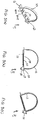
- Backing plate 51 is shaped to define an enlarged transverse hole, or opening, 63 in close proximity to inner edge 59. Opening 63 is positioned to directly align with strap accepting channel 43 when backing plate 51 is pivoted rearward about neck 53 and into contact against bottom surface 25 of strap 13 and rear wall 33 of locking head 15, as shown in Fig. 2(a) .
- opening 63 has the same general dimensions in transverse cross-section as strap accepting channel 43 at rear wall 33 so that backing plate 51 does not interfere with the insertion of strap 13 through apertured locking head 15.
- Backing plate 51 is additionally shaped to define a plurality of transverse slots 65-1 thru 65-6 that are formed in parallel in plate 51 at various locations along its length.
- Each slot 65 preferably has the same general dimensions in transverse cross-section as strap 13.
- strap 13 is appropriately dimensioned to be fittingly inserted through one of slots 65 when tie 11 is formed into its closed loop configuration, as will be explained further below.
- neck 53 is a shortened tabular member that connects outer end wall 37 of locking head 15 to inner edge 59 of backing plate 51, the width of neck 53 being approximately equal to the width of strap 13.
- Neck 53 includes a stiffened, or rigid, inner portion 67 that forms the connection with outer end wall 37 and a flexible outer portion 69 that forms the connection with backing plate 51.
- Inner portion 67 preferably has the same approximate thickness and rigidity as strap 13.
- outer portion 69 preferably has a thickness that is considerably less than the thickness of strap 13.
- cable tie 11 is designed to flex through reduced thickness portion 69.
- neck 53 functions as a living hinge through which backing plate 51 can pivot relative to locking head 15.
- Cable tie 11 is initially constructed such that backing plate 51 extends orthogonally out from outer end wall 37 and lies in a generally coplanar relationship with strap 13, as shown in Figs. 1(a) and 1(b) .
- front surface 55 of backing plate 51 lies in the same plane defined by front surface 23 of strap 13 and rear surface 57 of backing plate 51 lies in the same plane defined by bottom surface 25 of strap 13.
- neck 53 enables backing plate 51 to be pivoted rearward until rear surface 57 of backing plate 51 contacts both rear wall 33 of locking head 15 and a section of bottom surface 25 of strap 13, as shown in Figs. 2(a)-(c) .
- cable tie 11 Disposed in this folded condition, cable tie 11 is able to secure an article of commerce to its corresponding packaging without imparting any damage to the packaging, which is a principal object of the present invention.
- tie 11 can be used in the following manner to secure an article of commerce to its corresponding packaging.
- cable tie 11 is initially constructed such that backing plate 51 extends orthogonally out from outer end wall 37 so as to lie in a generally coplanar relationship with strap 13, as shown in Figs. 1(a) and 1(b) .
- backing plate 51 is pivoted rearward such that rear surface 57 of backing plate 51 is drawn towards rear wall 33 of locking head 15 and bottom surface 25 of strap 13, as shown in Figs. 2(a)-(c) .
- backing plate 51 With the article of commerce disposed in position against the front surface of its corresponding packaging, exposed front surface 55 of backing plate 51 is disposed against the rear surface of the packaging. More specifically, backing plate 51 is preferably disposed against the rear surface of the packaging such that inner edge 59 and outer edge 61 are aligned on opposite sides of the article to be coupled.
- Free end 21 of strap 13 is then inserted through a slot 65 in backing plate 51 (i.e. in the direction from rear surface 57 to front surface 55), as shown in Figs. 3(a)-(c) .
- a slot 65 in backing plate 51 (i.e. in the direction from rear surface 57 to front surface 55), as shown in Figs. 3(a)-(c) .
- rear surface 57 of backing plate 51 abuts firmly against rear wall 33 of locking head 15 as well as against a section of bottom surface 25 of strap 13.
- Free end 21 of strap 13 is then passed forward through the packaging on one side of the article.
- a first narrow opening is formed in the packaging to facilitate insertion of strap 13 therethrough.
- Strap 13 is then wrapped transversely across the article and inserted rearward through a second narrow opening formed in the packaging.
- strap 13 is initially positioned such that opening 63 in backing plate 51 directly aligns with the second narrow opening formed in the packaging, thereby facilitating insertion of second end 21 of strap 13 through strap accepting channel 43. Additionally, strap 13 is preferably inserted through the particular slot 65 in backing plate 51 that is in closest alignment with the first narrow opening in the packaging. In this manner, it is to be understood that the inclusion of a plurality of parallel slots 65 in backing plate 51 enables strap 13 to wrap tightly around articles of varying widths. In this manner, it is envisioned that cable tie 11 could be utilized in a wide variety of potential applications.
- Cable tie 11 is formed into a closed loop by inserting free end 21 of strap 13 through strap accepting channel 43 in in locking head 15, as seen in Figs. 3(a)-(c) .
- free end 21 of serrated strap 13 is advanced through locking head 15 until strap 13 cinches tightly across the article, with pawl 45 lockably engaging ratchet-shaped teeth 29 to prevent withdrawal, or backing out, of strap 13 from locking head 15.
- the engagement of pawl 45 onto strap 13 secures cinched cable tie 11 in its closed loop configuration and thereby retains the article firmly against the front surface of the packaging.
Landscapes
- Engineering & Computer Science (AREA)
- Mechanical Engineering (AREA)
- Package Frames And Binding Bands (AREA)
- Supports For Pipes And Cables (AREA)
Claims (13)
- Attache (11) de câble comportant :(a) une tête (15) formée pour inclure un canal (43) de réception de sangle allongé, la tête (15) comportant un tenon de verrouillage (45) qui est disposé pour faire saillie dans le canal (43) de réception de sangle ;(b) une sangle (13) ayant une première extrémité (19) et une seconde extrémité (21), la première extrémité (19) étant constituée sur la tête (15), la sangle (13) étant dimensionnée pour une insertion dans le canal (43) de réception de sangle de sorte que l'attache (11) de câble constitue une boucle fermée, la sangle (13) étant adaptée pour être en mise en prise par le tenon de verrouillage (45) lorsque l'attache (11) est constituée en une boucle fermée ; et(c) un élément de support (17) constitué sur la tête (15), l'élément de support (17) comportant une plaque d'adossement (51) qui a une largeur supérieure à une largeur de la tête (15) et une longueur plus longue qu'une longueur de la tête (15), la plaque d'adossement (51) définit une pluralité de fentes transversales (65) qui sont agencées en parallèle, chaque fente (65) étant dimensionnée pour recevoir la sangle (13) de manière ajustée et la plaque d'adossement (51) est accouplée pivotante à la tête (15) à travers un col (53) souple et la plaque d'adossement (51) définit un trou transversal (63) qui s'aligne sur le canal (43) de réception de sangle dans la tête (15) lorsque l'attache (11) de câble est pliée autour du col (53) souple.
- Attache (11) de câble selon la revendication 1, dans laquelle l'attache (11) de câble est conçue en tant qu'élément en plastique d'un seul tenant.
- Attache (11) de câble selon la revendication 2, dans laquelle la plaque d'adossement (51) est plane.
- Attache (11) de câble selon la revendication 3, dans laquelle la plaque d'adossement (51) a une empreinte rectangulaire.
- Attache (11) de câble selon la revendication 2, dans laquelle la plaque d'adossement (51) inclut une surface avant (55) sensiblement plate, une surface arrière (57) sensiblement plate, un bord intérieur (59) et un bord extérieur (61).
- Attache (11) de câble selon la revendication 5, dans laquelle la tête (15) inclut une paroi avant (31), une paroi arrière (33), une paroi d'extrémité intérieure (35), une paroi d'extrémité extérieure (37) et une paire de parois latérales (39, 41) qui définissent ensemble le canal (43) allongé.
- Attache (11) de câble selon la revendication 6, dans laquelle la surface avant (55) plate de la plaque d'adossement (51) est supérieure en superficie à la paroi avant (31) de la tête (15).
- Attache (11) de câble selon la revendication 7, dans laquelle la plaque d'adossement (51) est constituée sur la paroi d'extrémité extérieure (37) de la tête (15) et s'étend orthogonalement à partir de celle-ci.
- Attache (11) de câble selon la revendication 8, dans laquelle le col (53) relie le bord intérieur (59) de la plaque d'adossement (51) à la paroi d'extrémité extérieure (37) de la tête (15).
- Attache (11) de câble selon la revendication 9, dans laquelle au moins une portion du col (53) a une épaisseur qui est inférieure à l'épaisseur de la sangle (13).
- Attache (11) de câble selon la revendication 8, dans laquelle l'attache (11) de câble est adaptée pour être pliée autour du col (53) souple, de sorte que la surface arrière (57) de la plaque d'adossement (51) bute contre la paroi arrière (33) de la tête (15).
- Attache (11) de câble selon la revendication 1, dans laquelle la sangle (13) a la forme d'une bande souple allongée comportant une surface avant (23) et la surface de fond (25).
- Attache (11) de câble selon la revendication 12, dans laquelle une pluralité de dents en forme de cliquets (29) sont constituées sur la surface de fond (25) de la sangle (13), la pluralité de dents en forme de cliquets (29) étant conçues pour être mises en prise séquentiellement par le tenon de verrouillage (45) lorsque l'attache (11) de câble est constituée en une boucle fermée.
Applications Claiming Priority (2)
| Application Number | Priority Date | Filing Date | Title |
|---|---|---|---|
| US14/634,935 US9611083B2 (en) | 2015-03-02 | 2015-03-02 | Cable tie with support member |
| PCT/US2016/020322 WO2016140997A1 (fr) | 2015-03-02 | 2016-03-02 | Attache de câble à élément de support |
Publications (2)
| Publication Number | Publication Date |
|---|---|
| EP3265398A1 EP3265398A1 (fr) | 2018-01-10 |
| EP3265398B1 true EP3265398B1 (fr) | 2019-04-17 |
Family
ID=55543084
Family Applications (1)
| Application Number | Title | Priority Date | Filing Date |
|---|---|---|---|
| EP16710563.4A Active EP3265398B1 (fr) | 2015-03-02 | 2016-03-02 | Attache de câble à élément de support |
Country Status (6)
| Country | Link |
|---|---|
| US (1) | US9611083B2 (fr) |
| EP (1) | EP3265398B1 (fr) |
| CN (1) | CN107428444B (fr) |
| ES (1) | ES2732743T3 (fr) |
| TR (1) | TR201906695T4 (fr) |
| WO (1) | WO2016140997A1 (fr) |
Families Citing this family (10)
| Publication number | Priority date | Publication date | Assignee | Title |
|---|---|---|---|---|
| US10435214B2 (en) | 2017-01-04 | 2019-10-08 | Brian Kuperus | Tie-wrap assembly and method for using the same |
| US20180187703A1 (en) * | 2017-01-04 | 2018-07-05 | Brian Kuperus | Tie-wrap assembly and method for using the same |
| US10994906B2 (en) | 2017-10-23 | 2021-05-04 | Erik Vaclav Chmelar | Easy-to-remove cable tie |
| US11271378B2 (en) * | 2018-12-28 | 2022-03-08 | Commscope Technologies Llc | Devices and methods for holding cables |
| AU2020355257B2 (en) | 2019-09-28 | 2022-05-12 | Tas Medical Inc. | Systems, devices and methods for tissue fixation and approximating tissue defects |
| WO2021151103A1 (fr) | 2020-01-26 | 2021-07-29 | Tas Medical Inc. | Systèmes, dispositifs et procédés conçus pour fixer des tissus et rapprocher des défauts tissulaires |
| US11842657B2 (en) * | 2020-11-30 | 2023-12-12 | Travis Dacey | Magnetic labeling kit and methods of use |
| US20240150162A1 (en) * | 2022-11-07 | 2024-05-09 | Panduit Corp. | Cable Tie Handle |
| CN115783368B (zh) * | 2023-02-07 | 2023-04-28 | 昆明华信金属材料制造有限公司 | 一种防止包装原料破损功能的钢卷打包装置 |
| US12351375B2 (en) | 2023-02-28 | 2025-07-08 | Brian Kuperus | Ligation assembly and method for using the same |
Family Cites Families (11)
| Publication number | Priority date | Publication date | Assignee | Title |
|---|---|---|---|---|
| DE3312870A1 (de) * | 1983-04-09 | 1984-10-11 | Henkel KGaA, 4000 Düsseldorf | Verschluss fuer einen waeschetransportsack |
| US4805856A (en) * | 1987-12-29 | 1989-02-21 | Panduit Corp. | Cable mount |
| BR9203596A (pt) | 1992-09-15 | 1994-03-22 | Elc Prod Seguranca Ind | Selo de seguranca |
| US5636412A (en) * | 1995-11-01 | 1997-06-10 | The Procter & Gamble Company | Fixed circumference binding device with non-protruding free end and method for binding therewith |
| US5839169A (en) * | 1997-05-30 | 1998-11-24 | Dsc Telecom L.P. | Cable tie with safety guard |
| US6235369B1 (en) * | 1997-09-03 | 2001-05-22 | Velcro Industries B.V. | Strip-form fastening and dispensing |
| US5964013A (en) | 1997-12-09 | 1999-10-12 | Bergstrom; John A | Cable tie with cable protection features |
| US6449808B1 (en) * | 2000-08-10 | 2002-09-17 | E. J. Brooks Company | Security seal with flag grip |
| US6640393B2 (en) * | 2002-02-27 | 2003-11-04 | Todd B. Wendle | Releasable tie |
| CN100374357C (zh) * | 2003-01-14 | 2008-03-12 | 汉斯厄蒂克机械和设备工厂有限公司 | 具有可塑性变形的耳状物的敞开型软管夹紧件及其制造方法 |
| JP4285605B2 (ja) * | 2003-11-25 | 2009-06-24 | 株式会社エスケイ工機 | 封緘具 |
-
2015
- 2015-03-02 US US14/634,935 patent/US9611083B2/en not_active Expired - Fee Related
-
2016
- 2016-03-02 EP EP16710563.4A patent/EP3265398B1/fr active Active
- 2016-03-02 TR TR2019/06695T patent/TR201906695T4/tr unknown
- 2016-03-02 CN CN201680013220.5A patent/CN107428444B/zh not_active Expired - Fee Related
- 2016-03-02 WO PCT/US2016/020322 patent/WO2016140997A1/fr not_active Ceased
- 2016-03-02 ES ES16710563T patent/ES2732743T3/es active Active
Non-Patent Citations (1)
| Title |
|---|
| None * |
Also Published As
| Publication number | Publication date |
|---|---|
| US9611083B2 (en) | 2017-04-04 |
| ES2732743T3 (es) | 2019-11-25 |
| WO2016140997A1 (fr) | 2016-09-09 |
| TR201906695T4 (tr) | 2019-05-21 |
| CN107428444B (zh) | 2019-07-30 |
| CN107428444A (zh) | 2017-12-01 |
| US20160257466A1 (en) | 2016-09-08 |
| EP3265398A1 (fr) | 2018-01-10 |
Similar Documents
| Publication | Publication Date | Title |
|---|---|---|
| EP3265398B1 (fr) | Attache de câble à élément de support | |
| AU689907B2 (en) | Tie strips | |
| US7644475B2 (en) | Cable tie | |
| IE53285B1 (en) | Disposable one-piece security sealing device | |
| US20160061356A1 (en) | Fastner with Reusable Insert Fastening Element | |
| US20110220528A1 (en) | Packaged item including a packaging tie-down | |
| WO2018129027A1 (fr) | Ensemble d'emballage et procédé d'utilisation associé | |
| US5363536A (en) | Closing band | |
| US6640394B1 (en) | Tamper-proof tie | |
| US10077146B2 (en) | Packaging tie | |
| US7062820B1 (en) | Hand removable tote box lid retainer | |
| US6523228B1 (en) | Tamper-proof tie | |
| US9751670B2 (en) | Twist off cable tie fastener | |
| US20120233818A1 (en) | Cable tie with an improved buckle | |
| US6536082B2 (en) | Tamper-proof tie | |
| US20180187703A1 (en) | Tie-wrap assembly and method for using the same | |
| EP3186110B1 (fr) | Dispositif de fixation avec élément de fixation à pièce rapportée réutilisable | |
| KR200481667Y1 (ko) | 포장용 결속밴드 | |
| JPH0823364B2 (ja) | クリツプ | |
| CN111003357A (zh) | 具有用于产品触及的开口的包装系统 | |
| US20020166824A1 (en) | Method for loading merchandise onto pegboard display | |
| GB2331548A (en) | One-piece plastics tie | |
| JP3092292U (ja) | 結束具 | |
| JP3113633U (ja) | 把手付き自動ロックカム式結束バンド | |
| JPS5951062A (ja) | 荷造り用安全保護パツト |
Legal Events
| Date | Code | Title | Description |
|---|---|---|---|
| STAA | Information on the status of an ep patent application or granted ep patent |
Free format text: STATUS: THE INTERNATIONAL PUBLICATION HAS BEEN MADE |
|
| PUAI | Public reference made under article 153(3) epc to a published international application that has entered the european phase |
Free format text: ORIGINAL CODE: 0009012 |
|
| STAA | Information on the status of an ep patent application or granted ep patent |
Free format text: STATUS: REQUEST FOR EXAMINATION WAS MADE |
|
| 17P | Request for examination filed |
Effective date: 20170907 |
|
| AK | Designated contracting states |
Kind code of ref document: A1 Designated state(s): AL AT BE BG CH CY CZ DE DK EE ES FI FR GB GR HR HU IE IS IT LI LT LU LV MC MK MT NL NO PL PT RO RS SE SI SK SM TR |
|
| AX | Request for extension of the european patent |
Extension state: BA ME |
|
| DAV | Request for validation of the european patent (deleted) | ||
| DAX | Request for extension of the european patent (deleted) | ||
| GRAP | Despatch of communication of intention to grant a patent |
Free format text: ORIGINAL CODE: EPIDOSNIGR1 |
|
| STAA | Information on the status of an ep patent application or granted ep patent |
Free format text: STATUS: GRANT OF PATENT IS INTENDED |
|
| INTG | Intention to grant announced |
Effective date: 20181206 |
|
| GRAS | Grant fee paid |
Free format text: ORIGINAL CODE: EPIDOSNIGR3 |
|
| GRAA | (expected) grant |
Free format text: ORIGINAL CODE: 0009210 |
|
| STAA | Information on the status of an ep patent application or granted ep patent |
Free format text: STATUS: THE PATENT HAS BEEN GRANTED |
|
| AK | Designated contracting states |
Kind code of ref document: B1 Designated state(s): AL AT BE BG CH CY CZ DE DK EE ES FI FR GB GR HR HU IE IS IT LI LT LU LV MC MK MT NL NO PL PT RO RS SE SI SK SM TR |
|
| REG | Reference to a national code |
Ref country code: GB Ref legal event code: FG4D |
|
| REG | Reference to a national code |
Ref country code: CH Ref legal event code: EP |
|
| REG | Reference to a national code |
Ref country code: DE Ref legal event code: R096 Ref document number: 602016012554 Country of ref document: DE |
|
| REG | Reference to a national code |
Ref country code: AT Ref legal event code: REF Ref document number: 1121298 Country of ref document: AT Kind code of ref document: T Effective date: 20190515 Ref country code: IE Ref legal event code: FG4D |
|
| REG | Reference to a national code |
Ref country code: NL Ref legal event code: MP Effective date: 20190417 |
|
| REG | Reference to a national code |
Ref country code: LT Ref legal event code: MG4D |
|
| PG25 | Lapsed in a contracting state [announced via postgrant information from national office to epo] |
Ref country code: NL Free format text: LAPSE BECAUSE OF FAILURE TO SUBMIT A TRANSLATION OF THE DESCRIPTION OR TO PAY THE FEE WITHIN THE PRESCRIBED TIME-LIMIT Effective date: 20190417 |
|
| PG25 | Lapsed in a contracting state [announced via postgrant information from national office to epo] |
Ref country code: HR Free format text: LAPSE BECAUSE OF FAILURE TO SUBMIT A TRANSLATION OF THE DESCRIPTION OR TO PAY THE FEE WITHIN THE PRESCRIBED TIME-LIMIT Effective date: 20190417 Ref country code: LT Free format text: LAPSE BECAUSE OF FAILURE TO SUBMIT A TRANSLATION OF THE DESCRIPTION OR TO PAY THE FEE WITHIN THE PRESCRIBED TIME-LIMIT Effective date: 20190417 Ref country code: NO Free format text: LAPSE BECAUSE OF FAILURE TO SUBMIT A TRANSLATION OF THE DESCRIPTION OR TO PAY THE FEE WITHIN THE PRESCRIBED TIME-LIMIT Effective date: 20190717 Ref country code: SE Free format text: LAPSE BECAUSE OF FAILURE TO SUBMIT A TRANSLATION OF THE DESCRIPTION OR TO PAY THE FEE WITHIN THE PRESCRIBED TIME-LIMIT Effective date: 20190417 Ref country code: FI Free format text: LAPSE BECAUSE OF FAILURE TO SUBMIT A TRANSLATION OF THE DESCRIPTION OR TO PAY THE FEE WITHIN THE PRESCRIBED TIME-LIMIT Effective date: 20190417 Ref country code: AL Free format text: LAPSE BECAUSE OF FAILURE TO SUBMIT A TRANSLATION OF THE DESCRIPTION OR TO PAY THE FEE WITHIN THE PRESCRIBED TIME-LIMIT Effective date: 20190417 Ref country code: PT Free format text: LAPSE BECAUSE OF FAILURE TO SUBMIT A TRANSLATION OF THE DESCRIPTION OR TO PAY THE FEE WITHIN THE PRESCRIBED TIME-LIMIT Effective date: 20190817 |
|
| REG | Reference to a national code |
Ref country code: ES Ref legal event code: FG2A Ref document number: 2732743 Country of ref document: ES Kind code of ref document: T3 Effective date: 20191125 |
|
| PG25 | Lapsed in a contracting state [announced via postgrant information from national office to epo] |
Ref country code: GR Free format text: LAPSE BECAUSE OF FAILURE TO SUBMIT A TRANSLATION OF THE DESCRIPTION OR TO PAY THE FEE WITHIN THE PRESCRIBED TIME-LIMIT Effective date: 20190718 Ref country code: BG Free format text: LAPSE BECAUSE OF FAILURE TO SUBMIT A TRANSLATION OF THE DESCRIPTION OR TO PAY THE FEE WITHIN THE PRESCRIBED TIME-LIMIT Effective date: 20190717 Ref country code: LV Free format text: LAPSE BECAUSE OF FAILURE TO SUBMIT A TRANSLATION OF THE DESCRIPTION OR TO PAY THE FEE WITHIN THE PRESCRIBED TIME-LIMIT Effective date: 20190417 Ref country code: RS Free format text: LAPSE BECAUSE OF FAILURE TO SUBMIT A TRANSLATION OF THE DESCRIPTION OR TO PAY THE FEE WITHIN THE PRESCRIBED TIME-LIMIT Effective date: 20190417 Ref country code: PL Free format text: LAPSE BECAUSE OF FAILURE TO SUBMIT A TRANSLATION OF THE DESCRIPTION OR TO PAY THE FEE WITHIN THE PRESCRIBED TIME-LIMIT Effective date: 20190417 |
|
| REG | Reference to a national code |
Ref country code: AT Ref legal event code: MK05 Ref document number: 1121298 Country of ref document: AT Kind code of ref document: T Effective date: 20190417 |
|
| PG25 | Lapsed in a contracting state [announced via postgrant information from national office to epo] |
Ref country code: IS Free format text: LAPSE BECAUSE OF FAILURE TO SUBMIT A TRANSLATION OF THE DESCRIPTION OR TO PAY THE FEE WITHIN THE PRESCRIBED TIME-LIMIT Effective date: 20190817 |
|
| REG | Reference to a national code |
Ref country code: DE Ref legal event code: R097 Ref document number: 602016012554 Country of ref document: DE |
|
| PG25 | Lapsed in a contracting state [announced via postgrant information from national office to epo] |
Ref country code: EE Free format text: LAPSE BECAUSE OF FAILURE TO SUBMIT A TRANSLATION OF THE DESCRIPTION OR TO PAY THE FEE WITHIN THE PRESCRIBED TIME-LIMIT Effective date: 20190417 Ref country code: DK Free format text: LAPSE BECAUSE OF FAILURE TO SUBMIT A TRANSLATION OF THE DESCRIPTION OR TO PAY THE FEE WITHIN THE PRESCRIBED TIME-LIMIT Effective date: 20190417 Ref country code: AT Free format text: LAPSE BECAUSE OF FAILURE TO SUBMIT A TRANSLATION OF THE DESCRIPTION OR TO PAY THE FEE WITHIN THE PRESCRIBED TIME-LIMIT Effective date: 20190417 Ref country code: CZ Free format text: LAPSE BECAUSE OF FAILURE TO SUBMIT A TRANSLATION OF THE DESCRIPTION OR TO PAY THE FEE WITHIN THE PRESCRIBED TIME-LIMIT Effective date: 20190417 Ref country code: RO Free format text: LAPSE BECAUSE OF FAILURE TO SUBMIT A TRANSLATION OF THE DESCRIPTION OR TO PAY THE FEE WITHIN THE PRESCRIBED TIME-LIMIT Effective date: 20190417 Ref country code: SK Free format text: LAPSE BECAUSE OF FAILURE TO SUBMIT A TRANSLATION OF THE DESCRIPTION OR TO PAY THE FEE WITHIN THE PRESCRIBED TIME-LIMIT Effective date: 20190417 |
|
| PLBE | No opposition filed within time limit |
Free format text: ORIGINAL CODE: 0009261 |
|
| STAA | Information on the status of an ep patent application or granted ep patent |
Free format text: STATUS: NO OPPOSITION FILED WITHIN TIME LIMIT |
|
| PG25 | Lapsed in a contracting state [announced via postgrant information from national office to epo] |
Ref country code: SM Free format text: LAPSE BECAUSE OF FAILURE TO SUBMIT A TRANSLATION OF THE DESCRIPTION OR TO PAY THE FEE WITHIN THE PRESCRIBED TIME-LIMIT Effective date: 20190417 |
|
| 26N | No opposition filed |
Effective date: 20200120 |
|
| PG25 | Lapsed in a contracting state [announced via postgrant information from national office to epo] |
Ref country code: SI Free format text: LAPSE BECAUSE OF FAILURE TO SUBMIT A TRANSLATION OF THE DESCRIPTION OR TO PAY THE FEE WITHIN THE PRESCRIBED TIME-LIMIT Effective date: 20190417 |
|
| REG | Reference to a national code |
Ref country code: DE Ref legal event code: R119 Ref document number: 602016012554 Country of ref document: DE |
|
| PG25 | Lapsed in a contracting state [announced via postgrant information from national office to epo] |
Ref country code: MC Free format text: LAPSE BECAUSE OF FAILURE TO SUBMIT A TRANSLATION OF THE DESCRIPTION OR TO PAY THE FEE WITHIN THE PRESCRIBED TIME-LIMIT Effective date: 20190417 |
|
| REG | Reference to a national code |
Ref country code: CH Ref legal event code: PL |
|
| REG | Reference to a national code |
Ref country code: BE Ref legal event code: MM Effective date: 20200331 |
|
| PG25 | Lapsed in a contracting state [announced via postgrant information from national office to epo] |
Ref country code: LU Free format text: LAPSE BECAUSE OF NON-PAYMENT OF DUE FEES Effective date: 20200302 |
|
| PG25 | Lapsed in a contracting state [announced via postgrant information from national office to epo] |
Ref country code: IE Free format text: LAPSE BECAUSE OF NON-PAYMENT OF DUE FEES Effective date: 20200302 Ref country code: FR Free format text: LAPSE BECAUSE OF NON-PAYMENT OF DUE FEES Effective date: 20200331 Ref country code: LI Free format text: LAPSE BECAUSE OF NON-PAYMENT OF DUE FEES Effective date: 20200331 Ref country code: CH Free format text: LAPSE BECAUSE OF NON-PAYMENT OF DUE FEES Effective date: 20200331 Ref country code: DE Free format text: LAPSE BECAUSE OF NON-PAYMENT OF DUE FEES Effective date: 20201001 |
|
| PG25 | Lapsed in a contracting state [announced via postgrant information from national office to epo] |
Ref country code: BE Free format text: LAPSE BECAUSE OF NON-PAYMENT OF DUE FEES Effective date: 20200331 |
|
| GBPC | Gb: european patent ceased through non-payment of renewal fee |
Effective date: 20200302 |
|
| PG25 | Lapsed in a contracting state [announced via postgrant information from national office to epo] |
Ref country code: GB Free format text: LAPSE BECAUSE OF NON-PAYMENT OF DUE FEES Effective date: 20200302 |
|
| REG | Reference to a national code |
Ref country code: ES Ref legal event code: FD2A Effective date: 20210727 |
|
| PG25 | Lapsed in a contracting state [announced via postgrant information from national office to epo] |
Ref country code: IT Free format text: LAPSE BECAUSE OF NON-PAYMENT OF DUE FEES Effective date: 20200302 |
|
| PG25 | Lapsed in a contracting state [announced via postgrant information from national office to epo] |
Ref country code: ES Free format text: LAPSE BECAUSE OF NON-PAYMENT OF DUE FEES Effective date: 20200303 |
|
| PG25 | Lapsed in a contracting state [announced via postgrant information from national office to epo] |
Ref country code: MT Free format text: LAPSE BECAUSE OF FAILURE TO SUBMIT A TRANSLATION OF THE DESCRIPTION OR TO PAY THE FEE WITHIN THE PRESCRIBED TIME-LIMIT Effective date: 20190417 Ref country code: CY Free format text: LAPSE BECAUSE OF FAILURE TO SUBMIT A TRANSLATION OF THE DESCRIPTION OR TO PAY THE FEE WITHIN THE PRESCRIBED TIME-LIMIT Effective date: 20190417 |
|
| PG25 | Lapsed in a contracting state [announced via postgrant information from national office to epo] |
Ref country code: MK Free format text: LAPSE BECAUSE OF FAILURE TO SUBMIT A TRANSLATION OF THE DESCRIPTION OR TO PAY THE FEE WITHIN THE PRESCRIBED TIME-LIMIT Effective date: 20190417 |