EP3265996B1 - Quantification de gaz en imagerie de gaz optique passive - Google Patents
Quantification de gaz en imagerie de gaz optique passive Download PDFInfo
- Publication number
- EP3265996B1 EP3265996B1 EP16721356.0A EP16721356A EP3265996B1 EP 3265996 B1 EP3265996 B1 EP 3265996B1 EP 16721356 A EP16721356 A EP 16721356A EP 3265996 B1 EP3265996 B1 EP 3265996B1
- Authority
- EP
- European Patent Office
- Prior art keywords
- gas
- infrared
- scene
- wavelength band
- image
- Prior art date
- Legal status (The legal status is an assumption and is not a legal conclusion. Google has not performed a legal analysis and makes no representation as to the accuracy of the status listed.)
- Active
Links
Images


Classifications
-
- G—PHYSICS
- G01—MEASURING; TESTING
- G01N—INVESTIGATING OR ANALYSING MATERIALS BY DETERMINING THEIR CHEMICAL OR PHYSICAL PROPERTIES
- G01N21/00—Investigating or analysing materials by the use of optical means, i.e. using sub-millimetre waves, infrared, visible or ultraviolet light
- G01N21/17—Systems in which incident light is modified in accordance with the properties of the material investigated
- G01N21/25—Colour; Spectral properties, i.e. comparison of effect of material on the light at two or more different wavelengths or wavelength bands
- G01N21/31—Investigating relative effect of material at wavelengths characteristic of specific elements or molecules, e.g. atomic absorption spectrometry
- G01N21/35—Investigating relative effect of material at wavelengths characteristic of specific elements or molecules, e.g. atomic absorption spectrometry using infrared light
- G01N21/3504—Investigating relative effect of material at wavelengths characteristic of specific elements or molecules, e.g. atomic absorption spectrometry using infrared light for analysing gases, e.g. multi-gas analysis
- G01N21/3518—Devices using gas filter correlation techniques; Devices using gas pressure modulation techniques
-
- G—PHYSICS
- G01—MEASURING; TESTING
- G01N—INVESTIGATING OR ANALYSING MATERIALS BY DETERMINING THEIR CHEMICAL OR PHYSICAL PROPERTIES
- G01N21/00—Investigating or analysing materials by the use of optical means, i.e. using sub-millimetre waves, infrared, visible or ultraviolet light
- G01N21/17—Systems in which incident light is modified in accordance with the properties of the material investigated
- G01N21/25—Colour; Spectral properties, i.e. comparison of effect of material on the light at two or more different wavelengths or wavelength bands
- G01N21/31—Investigating relative effect of material at wavelengths characteristic of specific elements or molecules, e.g. atomic absorption spectrometry
- G01N21/35—Investigating relative effect of material at wavelengths characteristic of specific elements or molecules, e.g. atomic absorption spectrometry using infrared light
- G01N21/3504—Investigating relative effect of material at wavelengths characteristic of specific elements or molecules, e.g. atomic absorption spectrometry using infrared light for analysing gases, e.g. multi-gas analysis
-
- G—PHYSICS
- G06—COMPUTING OR CALCULATING; COUNTING
- G06T—IMAGE DATA PROCESSING OR GENERATION, IN GENERAL
- G06T5/00—Image enhancement or restoration
- G06T5/50—Image enhancement or restoration using two or more images, e.g. averaging or subtraction
-
- G—PHYSICS
- G01—MEASURING; TESTING
- G01N—INVESTIGATING OR ANALYSING MATERIALS BY DETERMINING THEIR CHEMICAL OR PHYSICAL PROPERTIES
- G01N21/00—Investigating or analysing materials by the use of optical means, i.e. using sub-millimetre waves, infrared, visible or ultraviolet light
- G01N21/17—Systems in which incident light is modified in accordance with the properties of the material investigated
- G01N21/25—Colour; Spectral properties, i.e. comparison of effect of material on the light at two or more different wavelengths or wavelength bands
- G01N21/31—Investigating relative effect of material at wavelengths characteristic of specific elements or molecules, e.g. atomic absorption spectrometry
- G01N21/35—Investigating relative effect of material at wavelengths characteristic of specific elements or molecules, e.g. atomic absorption spectrometry using infrared light
- G01N21/3504—Investigating relative effect of material at wavelengths characteristic of specific elements or molecules, e.g. atomic absorption spectrometry using infrared light for analysing gases, e.g. multi-gas analysis
- G01N2021/3531—Investigating relative effect of material at wavelengths characteristic of specific elements or molecules, e.g. atomic absorption spectrometry using infrared light for analysing gases, e.g. multi-gas analysis without instrumental source, i.e. radiometric
-
- G—PHYSICS
- G06—COMPUTING OR CALCULATING; COUNTING
- G06T—IMAGE DATA PROCESSING OR GENERATION, IN GENERAL
- G06T2207/00—Indexing scheme for image analysis or image enhancement
- G06T2207/10—Image acquisition modality
- G06T2207/10048—Infrared image
-
- G—PHYSICS
- G06—COMPUTING OR CALCULATING; COUNTING
- G06T—IMAGE DATA PROCESSING OR GENERATION, IN GENERAL
- G06T2207/00—Indexing scheme for image analysis or image enhancement
- G06T2207/20—Special algorithmic details
- G06T2207/20212—Image combination
- G06T2207/20224—Image subtraction
Definitions
- the present disclosure relates generally to imaging and visualizing gas and, in particular, to imaging and visualizing quantified gas using infrared imaging systems and methods.
- Thermal, or infrared (IR) images of scenes are often useful for monitoring, inspection and/or maintenance purposes, e.g. for monitoring gas leaks at an industrial plant.
- a thermal imaging device e.g. in the form of a thermography arrangement or an infrared IR camera, is provided to capture infrared (IR) image data values, representing infrared radiation emitted from an observed scene.
- the captured IR image can after capturing be processed, displayed and/or saved, for example in the thermal imaging device or in a computing device connected to the thermal imaging device such as a tablet computer, a smartphone, a laptop or a desktop computer.
- Thermal imaging devices such as IR cameras, might be used for detecting gas occurrence, for example in the form of a gas cloud or gas plume e.g. from fugitive gas emissions or gas leaks, and for producing a visual representation of such gas occurrence as a gas image.
- a gas image can be used for visualizing gas occurrence or gas leaks, e.g. as smoke or a cloud on images presented on the viewfinder of a camera, on an integrated or separate display, or on an external computing device, thereby allowing the user to see gas occurrence in a scene observed and imaged by means of an IR camera.
- a variant of such techniques is called passive infrared gas imaging and is based on using radiation from a scene without any additional illumination for detecting gas.
- a problem with conventional systems is that the sensitivity of the thermal imaging device might be too low to detect gas below a certain gas particle concentration or, in other words, the contrast between gas information and noise/interference in a generated gas image is too low to identify gas.
- Another problem is that the sensitivity is further reduced by various physical aspects, such as varying temperatures and emissivity in the observed scene background, noise, other gases, aerosol particles and moving gas clouds.
- gas imaging may be based on the difference in absorption or transmission of infrared radiation in different wavelength bands.
- a problem, particularly with uncooled thermal imaging devices, is that when basing gas imaging on the difference in absorption or transmission of infrared radiation in selected wavelength bands, the bands cannot be made narrow due to high noise contribution by imaging device components such as filters, optical systems, wave guide and the detector itself. This means that physical characteristics of the system, such as noise or thermal interference might vary significantly with wavelength and will be more difficult to compensate for.
- gas imaging may be based on the difference in absorption or transmission of infrared radiation in different wavelength bands.
- a problem, particularly with uncooled thermal imaging devices, is that when basing gas imaging on the difference in absorption or transmission of infrared radiation in selected wavelength bands, the sensitivity of the thermal imaging device might be too low to quantify gas below a certain gas concentration or in other words the contrast between gas information and noise/interference in a generated gas infrared image is too low to quantify gas.
- quantification of gas is carried out by obtaining a gas-absorption-path-length image as a scene difference infrared image based on a gas infrared image and a scene background infrared image substantially depicting the same scene.
- a quantified scene difference infrared image is then generated based on said scene difference infrared image and a predefined gas-quantifying relation GQR according to the method of claim 1.
- the disclosure relates to imaging and visualizing quantified gas using infrared IR sensors or detectors and image processing.
- An example of a use case is the inspection with a thermal imaging device of a part of an industrial complex handling gas.
- the disclosure relates to passive gas imaging that uses thermal background radiation within the infrared region and can be used to image gas for example against a cold background, in this case imaging thermal emission or radiation from the gas, or used against a warm background, in that case imaging absorption by the gas of thermal radiation from the background.
- Imaging of gas is based on the difference in gas temperature T G and background temperature T B , hereinafter referred to as gas to background temperature difference ⁇ T.
- gas to background temperature difference ⁇ T the difference in gas temperature T G and background temperature T B
- the sensitivity of a thermal imaging system is dependent on the difference in gas temperature T G and background temperature T B ,
- Fig. 1 shows a schematic view of a method and an apparatus for passive imaging of gas based on background temperature difference ⁇ T 130, in accordance with one or more embodiments.
- a thermal imaging device 170 is adapted to capture radiation within controllable wavelength bands and thus to produce infrared images, herein also called IR images or thermal images, representing a particular selected wavelength band of infrared radiation from a scene.
- gas 160 e.g.
- the scene background 110 has a background temperature T B 122
- the gas has a gas temperature T G 121.
- a temperature difference parameter preferably in the form of a gas to background temperature difference ⁇ T 130 can be determined or calculated based on the background temperature T B 122 and the gas temperature T G 121 by a gas to background difference relation 140.
- a thermal imaging device 170 is configured and/or controlled to capture and/or generate a selection of inter alia a background IR image representing the thermal radiation from the background in a scene, a gas IR image representing a gas occurrence between the thermal imaging device and a background in a scene and/or a possible other IR image representing other phenomena in the scene.
- a gas-absorption-path-length image representing the length of the path of radiation from the scene background 110 through a gas occurrence in the scene can be generated based on a gas infrared image, a background infrared image and optionally the temperature difference parameter ⁇ T 130.
- a pixel value 181 derived from processed pixel values in a gas-absorption-path-length image is at least used to determine a quantified pixel value 182 indicative of concentration length by gas-quantifying relation GQR 180 in the form of a concentration length or concentration-path length product CL in parts per minute * meter ppm*m.
- quantified gas is visualized in a quantified gas visualization image presentable or presented to the user on a display, this image being based on pixel values of the gas-absorption-path-length image.
- a background temperature T B 122 derived from a pixel value in a background infrared image and a gas temperature T G 121 derived from a pixel value in a gas infrared image are used to determine the temperature difference parameter ⁇ T 130.
- the gas temperature T G is estimated based on a measured ambient air temperature retrieved from an ambient air temperature sensor and/or based on a previously captured gas IR image that comprises a representation of the intensity of infrared radiation within a first wavelength band A substantially including wavelengths of infrared radiation with high absorptance values for the gas in an absorption spectrum and/or low transmittance values in a transmission spectrum.
- the first wavelength band A is a high absorption wavelength band that includes wavelengths significantly affected by the presence of the gas to be imaged. In a case where the gas has a temperature higher than the ambient air temperature or the background temperature there is radiation from the gas in an emission spectrum.
- the first wavelength band A is herein also called high absorption wavelength band A.
- the background temperature T B is estimated based on a previously captured background IR image that comprises a representation of the intensity of infrared radiation within a second wavelength band B substantially including wavelengths of infrared radiation with low absorptance values for the gas in an absorption spectrum and/or high transmittance values in a transmission spectrum.
- the second wavelength band B is a low absorption wavelength band and/or a high transmission wavelength band that includes wavelengths insignificantly affected by the presence of the gas to be detected.
- the second wavelength band B is herein also called low absorption wavelength band B.
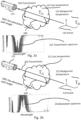
- Fig. 2a illustrates a method for imaging gas in accordance with one or more embodiments for example applicable in a situation where the background temperature T B 122 is higher than the gas temperature T G 121, i.e. the scene background is warmer than the gas 160.
- a fraction of the energy or infrared radiation emitted from the scene background 110 is transmitted through the gas 160, indicated as radiation transmission 250 with a gas-absorption-path length 1601, to the detector in a thermal imaging device 170.
- this fraction can be determined by using a predetermined relation for example based on a transmission spectrum 251.
- Fig. 2b illustrates a method for imaging gas in accordance with one or more embodiments for example applicable in a situation where the background temperature T B 122 is lower than the gas temperature T G 121, i.e. the scene background is colder than the gas.
- a fraction of the energy or infrared radiation emitted from the scene background 110 is transmitted through the gas, indicated as radiation transmission 250 with a gas-absorption-path length 1601, to the detector in a thermal imaging device 170.
- this transmitted fraction can be determined by using a predetermined relation for example based on an absorption spectrum 241.
- a background IR image and a gas IR image are generated. Based on the background IR image, on the gas IR image and dependent on a transmission spectrum 251 and/or on an absorption spectrum 241, a gas-absorption-path-length image with improved contrast is generated in a system with improved sensitivity and/or improved signal to noise ration.
- Fig. 3 illustrates one or more embodiments applied in a situation where the background temperature T B is lower than the gas temperature T G , i.e. the background is colder than the gas 160.
- the thermal imaging system 170 is controlled to capture radiation in a low absorption wavelength band B including wavelengths less affected or not so affected, i.e. insignificantly affected by the presence of the gas to be detected, and to capture radiation in a high absorption wavelength band A including wavelengths more affected, i.e. significantly affected by the presence of the gas to be detected.
- the thermal imaging system is controlled to capture radiation comprising a sum 380 of transmission through the gas and emission from the gas 160.
- a gas-absorption-path-length image is generated based on a transmission plus emission spectrum 381 being a sum of a transmission spectrum and an emission spectrum.
- Fig. 4 is a graph showing radiance from a scene in relation to wavelength in the infrared range, the scene comprising a background and a gas occurrence in the ambient atmosphere in the scene.
- this graph shows an example on how the gas temperature T G indicated with an intermittently drawn line, the background temperature T B indicated with a fully drawn line and the gas to background temperature difference ⁇ T 130, i.e. the difference T B -T G , varies with the wavelength of the infrared radiation from the scene.
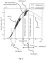
- Fig. 5 illustrates by means of a temperature/wavelength relation similar to that of Fig. 4 an example of one or more embodiments wherein a high absorption wavelength band A 510 and a low absorption wavelength band B 520 have been determined for the purpose to improve contrast in a generated gas-absorption-path-length image based on a predetermined absorption spectrum 241 of the gas, an estimated gas temperature T G 121 and an estimated background temperature T B 122.
- Wavelength band B 520 is selected to include wavelengths less affected or not so affected, i.e. insignificantly affected by the presence of the gas to be detected.
- Wavelength band A 510 is selected to include wavelengths more or strongly affected, i.e. significantly selected by the presence of the gas to be detected.
- wavelength band A 510 includes an absorption wavelength band G 505 from the absorption spectrum 241 ( Fig. 2b ), i.e. a subset of the absorption spectrum significantly affected by the presence of the gas to be imaged, or expressed in a different aspect as a subset of a transmission spectrum less affected by the presence of the gas to be imaged.
- the low absorption wavelength band B 520 at least partially overlaps wavelength band A 510, thereby minimizing variations between wavelength band A 510 and wavelength band B 520 in emission/emissivity represented by values in the emission spectrum.
- Another effect by one or more embodiments is an elimination or simplification of the complexity of compensating for varying emission/emissivity in a scene.
- Fig. 6 shows a schematic view of one or more embodiments of a thermal imaging device or system 170, e.g. in the form of a thermography arrangement or an infrared IR camera.
- the thermal imaging device 170 comprises a processor 612
- the thermal imaging device 170 comprises a first infrared (IR) imaging system 613 that is configured and/or controllable to capture infrared (IR) images in the form of IR image data values/pixel values, representing infrared radiation emitted from an observed scene within one or more selectable wavelength bands A, B or C.
- IR infrared
- the infrared (IR) imaging system 613 is further communicatively coupled to a processor 612.
- the first infrared (IR) imaging system 613 is further configured to receive control data and to trigger the capturing of an IR image of a scene within a selected wavelength band in response to said control data.
- the first infrared (IR) imaging system 613 is further arranged to send a signal frame or data frame of IR image data values representing a captured image to the processor 612.
- IR image data typically include data values for example represented in an instance of a data structure, such as an image data frame as mentioned.
- the processor/processing unit 612 is provided with specifically designed programming or program code portions adapted to control the processing unit to perform the steps and functions of one or more embodiments of the method and/or methods described herein.
- the thermal imaging device 170 further comprises at least one memory 615 configured to store data values or parameters received from a processor 612 or to retrieve and send data values or parameters to a processor 612.
- a communications interface 616 is configured to send or receive data values or parameters to or from a processor 612 to or from external or internal units or sensors via the communications interface 616.
- An optional input device 617 is configured to receive an input or an indication from a user, e.g. an input of a user indicating a command to execute the imaging of a gas-absorption-path-length image.
- the thermal imaging device 170 further comprises a display 618 configured to receive a signal from a processor 612 and to display the received signal as a displayed image, e.g. to display a visual representation of a gas-absorption-path-length image to a user of the thermal imaging device 170.
- the display 618 is integrated with a user input device 617 configured to receive a signal from a processor 612 and to display the received signal as a displayed image and receive input or indications from a user, e.g. by comprising touch screen functionality and to send a user input signal to said processor/processing unit 612.
- the thermal imaging device 170 further comprises an ambient air temperature sensor 619 configured to measure ambient air temperature and generate an ambient air temperature data value and provide the ambient air temperature data value to the processor 612 receiving, polling or retrieving the ambient air temperature data value.
- the ambient air temperature sensor 619 is communicatively coupled to the processor 612 directly or via the communications interface 616, and may be provided as an external or an internal unit.
- the thermal imaging device 170 further optionally comprises a second infrared (IR) imaging system 614, preferably with properties and functions similar to those of the first infrared (IR) imaging system 612 described above.
- the second infrared (IR) imaging system 614 is similarly configured and/or controllable to capture infrared (IR) images in the form of IR image data values/pixel values, representing infrared radiation emitted from an observed scene within one or more selectable wavelength bands A, B or C.
- the second infrared (IR) imaging system 614 is further communicatively coupled to a processor 612, and is further configured to receive control data and to trigger the capturing of an IR image of a scene within a selected wavelength band in response to said control data.
- the second infrared (IR) imaging system 614 is further arranged to send a signal frame of IR image data values representing an infrared (IR) image to the processor 612.
- the described infrared (IR) imaging systems 613, 614 each comprises an infrared (IR) optical system 6131, 6141, e.g. comprising a lens, possible zoom functionality and focus functionality 6131, together with a corresponding infrared (IR) sensor 6132, 6142, for example comprising a micro-bolometer focal plane array.
- IR infrared
- controllable / selectable wavelength bands Examples of controllable / selectable wavelength bands
- the described infrared (IR) imaging systems 613, 614 are configured and/or controllable to capture infrared (IR) images in the form of IR image data values/pixel values, representing infrared radiation emitted from an observed scene within a preferably continuous subset of a plurality of wavelength bands A, B or C.
- One or more of the wavelength bands may be at least partly overlapping.
- wavelength band A is selected as 7-9 ⁇ m and wavelength band B is selected as 9-15 ⁇ m
- the first infrared (IR) imaging system 613 is configured to capture gas IR images in the form of IR image data values/pixel values, representing infrared radiation emitted from an observed scene within 7-8.6um
- the second infrared (IR) imaging system 614 is configured to capture background IR images in the form of IR image data values/pixel values, representing infrared radiation emitted from an observed scene within 9-12 um.
- Table 1 shows examples of ranges of wavelength bands for different gases that may be used in embodiments described herein. So for example and as shown in the table, embodiments of a method or a device as described herein may be devised for operating on CO2 and would in this example have a high absorption wavelength band A in the range of 4,2 ⁇ m - 4,6 ⁇ m and a low absorption filter B in the range of 4,4 ⁇ m - 4,6 ⁇ m.
- Table 1 Examples of wavelength bands for different gases High absorption Low absorption Gas Wavelength band A Wavelength band B Methane 1 3,2 ⁇ m - 3,6 ⁇ m 3,4 ⁇ m - 3,6 ⁇ m Methane 2 7,0 ⁇ m - 9,0 ⁇ m 8,5 ⁇ m - 9,0 ⁇ m CO2 4,2 ⁇ m - 4,6 ⁇ m 4,4 ⁇ m - 4,6 ⁇ m CO + N20 4,52 ⁇ m - 4,87 ⁇ m 4,67 ⁇ m - 4,87 ⁇ m Refrigerants 8,0 ⁇ m - 9,0 ⁇ m 8,6 ⁇ m - 9,0 ⁇ m SF6 10,3 ⁇ m - 11,1 ⁇ m 10,7 ⁇ m - 11,1 ⁇ m
- Fig. 7a shows a schematic view of infrared sensors 6132, 6142 in a thermal imaging device 170 (cf. Fig. 6 ) configured to capture a gas IR image and a background IR image according to one or more embodiments. This can also be referred to as a spatial sensor configuration.
- a first infrared (IR) imaging system 613 (cf. Fig. 6 ), comprised in the thermal imaging device 170, comprises an image sensor 6132 configured to capture a gas IR image.
- the sensor 6132 is configured to capture infrared radiation within a high absorption wavelength band A.
- the first infrared (IR) imaging system 613 optionally comprises an optical gas filter 710 in the optical path of the sensor 6132 configured with a passband of infrared radiation within said high absorption wavelength band A.
- a second infrared (IR) imaging system 614 (cf. Fig. 6 ), comprised in the thermal imaging device 170, comprises an image sensor 6142 configured to capture a background IR image.
- the sensor 6142 is configured to capture infrared radiation within a low absorption wavelength band B.
- the second infrared (IR) imaging system 614 optionally comprises a background optical filter 720 in the optical path of the sensor 6142 configured with a passband of infrared radiation within said low absorption wavelength band B.
- the sensor 6132 comprised in the first infrared (IR) imaging system 613, is configured to capture a gas IR image simultaneously, substantially simultaneously, or with a time interval, with the sensor 6142, comprised in the second infrared (IR) imaging system 613, capturing a background IR image.
- IR infrared
- the processor 612 is adapted to send control data to the first infrared (IR) imaging system to trigger the sensor 6132 to capture infrared radiation within the high absorption wavelength band A, and/or is adapted to send control data the second infrared (IR) imaging system to trigger the sensor 6142 to capture infrared radiation within the low absorption wavelength band B.
- IR infrared
- the processor 612 is adapted to send control data to the first infrared (IR) imaging system to configure the gas optical filter 710 with a pass band equal to wavelength band A and adapted to send control data to the second infrared (IR) imaging system to configure the background optical filter 720 with a pass band equal to wavelength band B.
- IR infrared
- a combination of controllable sensor and controllable optical filter are provided in one or more embodiments.
- Fig. 7b shows a schematic view of an infrared sensor 6132, 6142 in a thermal imaging device 170 (cf. Fig. 6 ) configured to capture a gas IR image and a background IR image according to one or more embodiments.
- a first infrared (IR) imaging system 613 comprised in the thermal imaging device 170, comprises an image sensor 6132 configured to capture a gas IR image at time T 0 and a background IR image at time T 1 .
- the sensor 6132 is at time T 0 configured to capture infrared radiation within a high absorption wavelength band A.
- the first infrared (IR) imaging system 613 optionally comprises an optical filter 710 in the optical path of the sensor 6132 configured at time T 0 with a passband of infrared radiation equal to a high absorption wavelength band A and configured at time T 1 with a passband of infrared radiation equal to a low absorption wavelength band B.
- the processor 612 is adapted to send control data to the first infrared (IR) imaging system to configure the captured wavelength band of the sensor 6132 to the high absorption wavelength band A and to trigger the capturing of a gas IR image at time T 0 , and to configure the captured wavelength band of the sensor 6132 to the low absorption wavelength band B and to trigger the capturing of a gas IR image at time T 1 .
- IR infrared
- the processor 612 is adapted to send control data to the first infrared (IR) imaging system to configure the captured wavelength band of the sensor 6132 to the high absorption wavelength band A and to trigger the capturing of a gas IR image at time T 0
- the captured wavelength band of the sensor 6132 to the low absorption wavelength band B and to trigger the capturing of a gas IR image at time T 1 .
- there is a short time lapse between the time T 0 and the time T 1 suitably selected to reconfigure the sensor for different wavelength bands.
- the processor 612 is adapted to send control data to the first infrared (IR) imaging system to configure the optical filter 710 with a pass band equal to the high absorption wavelength band A at time T 0 and to configure the optical filter 710 with a pass band equal to the low absorption wavelength band B at time T 1 .
- IR infrared
- a combination of controllable sensor and controllable optical filter are provided in one or more embodiments also in a temporal sensor configuration.
- one or more embodiments relate to an improved system and method of imaging quantified gas, in particular passive infrared imaging of gas occurring in a scene.
- the gas is imaged based on a difference in an estimated gas temperature T G and an estimated background temperature T B . Consequently, a greater difference between T G and T B will result in a greater contrast in the imaged gas in relation to background.
- T G and T B the estimation of T G and T B are improved
- the sensitivity of the imaging system is improved and smaller amounts of gas can be detected and optionally imaged.
- the contrast of the imaged gas is improved, e.g. in a gas-absorption-path-length image representing the length of the path of radiation from the scene background 110 through a gas occurrence in the scene.
- Embodiments described herein thus increase the sensitivity of gas detection in an image, and thereby the contrast, by an improved and dynamic selection of a high absorption wavelength band A and a low absorption wavelength band B, e.g. based on previously captured gas and background IR images.
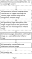
- Fig. 8 illustrates embodiments of a method of quantifying gas in a thermal imaging device, in accordance with one or more embodiments.
- Gas is quantified by obtaining a gas-absorption-path-length image as a scene difference infrared image and generating a quantified scene difference infrared image based on the scene difference infrared image and a predefined gas-quantifying relation, where an increased contrast has been obtained by finding an improved balance between gas detection signal to noise ratio by determining a first, high absorption wavelength band A and a second, low absorption wavelength band B.
- a method to quantify gas in a thermal imaging device 170 comprises a selection of: Step 810: Obtaining a gas-absorption-path-length image as a scene difference infrared image based on a gas infrared image 910 and a scene background infrared image 920 substantially depicting the same scene 110.
- the gas-absorption-path-length image is obtained by retrieving it from memory 615. In yet one example, the gas-absorption-path-length image is obtained generating a gas-absorption-path-length image by a processor 612.
- Step 820 Generating a quantified scene difference infrared image based on said scene difference infrared image and a predefined gas-quantifying relation 180.
- a quantified scene difference infrared image is generated by retrieving the gas-absorption-path-length image/scene difference infrared image and a predefined gas-quantifying relation 180 from memory 615.
- Each pixel in the quantified scene difference infrared image is determined by applying the gas-quantifying relation 180 to each pixel in the scene difference infrared image.
- the gas-quantifying relation describes the relation between scene difference infrared image pixel values 181,900 and quantified scene difference infrared image pixel values 182 in the form of a concentration length product expressed in parts per million * meter or ppm * m, e.g. by multiplying the gas concentration by the gas-absorption path length 1601.
- scene difference infrared image pixel values are generated by generating image pixel values as a selection of:
- the pixel values are for example represented by temperature values in degrees Celsius or Kelvin and the predefined gas-quantifying relation 180 is a look-up table, e.g. as depicted in relation to tables 1-4 in fig. 17 .
- the predefined gas-quantifying relation 180 is a look-up table, e.g. as depicted in relation to tables 1-4 in fig. 17 .
- concentration length product expressed in parts per million * meter or ppm * m.
- the gas-quantifying relation 180 is generated by:
- quantified scene difference infrared image pixel values 182 are measured using absorption spectroscopy in a controlled environment.
- a first set of measurement values or quantified scene difference infrared image pixel values 182 are obtained by varying the gas concentration and the gas-absorption path length 1601, e.g. by replacing sample glass vials with known gas concentration and known gas-absorption path length and monitoring the gas temperature T G and background temperature T B .
- the step 810 of obtaining a gas-absorption-path-length image further comprises and/or is preceded by:
- high absorption wavelength band A 510 includes an absorption wavelength band G 505 from the absorption spectrum 241.
- low absorption wavelength band B 520 may at least partially overlap high absorption wavelength band A 510. Examples of determining high absorption wavelength band A 510 and low absorption wavelength band B 520 are further described in relation to Fig. 12-16 .
- infrared imaging system control data comprising data indicating high absorption wavelength band A 510 and low absorption wavelength band B 520 and triggering information, is sent to a first and a second infrared imaging system 613,614.
- the control data is configured to control preferably the first infrared imaging system 613 to capture and return a gas infrared image of a scene comprising intensity of infrared radiation within high absorption wavelength band A 510.
- the control data is further configured to trigger preferably the second infrared imaging system 614 to capture a background infrared image of the scene comprising intensity of infrared radiation within low absorption wavelength band B 520.
- the first and second infrared imaging system 613,614 are integrated in the thermal imaging device 170.
- the first and second infrared imaging systems 613,614 are external to the thermal imaging device 170.
- the quantified scene difference infrared image pixel values 182 comprise temperature values, e.g. in degrees Celsius or Kelvin.
- the Noise Equivalent Temperature Difference NETD is measured as Root Mean Square RMS noise, ⁇ U noise , which is the noise voltage measured as a Root Mean Square value of the imaging systems video channel and then converted to the corresponding temperature difference in degrees Celsius or Kelvin.
- the high absorption-wavelength band A 510 is determined with a lower endpoint 5101 in the interval of [6-7.8 ⁇ m]-[8-9.6 ⁇ m]] and wherein wavelength band A 510 is determined with a higher endpoint 5502 in the interval of [8-9.6 ⁇ m].
- the high absorption wavelength band A and low absorption wavelength band B have to be quite broad compared to cooled cameras, as uncooled cameras have less sensitivity and a higher thermal noise contribution.
- the filter regions are quite broad not only absorption of for example the gas methane is present in the filter region but also water vapor. This means that water vapor has to be quantified as well as the gas, here methane.
- water related wavelength band C 530 determined and spectrally filtered where only water vapor absorbs the radiation, e.g. by capturing a water infrared image 1030 comprising infrared radiation within wavelength band C.
- Another example to compensate for water vapor is to measure the humidity in the air and the distance from the thermal imaging device 170 to the background scene 110 and assume the humidity is the same over this whole distance. The concentration length can then be estimated as measured humidity in ppm * distance from the thermal imaging device 170 to the background scene 110, thereby calculating the concentration length of water vapor in ppm ⁇ m.
- One or more embodiments further comprises: determining, by a processor 612, a third, water related wavelength band C 530 to improve contrast in a generated gas-absorption-path-length image based on a predetermined water absorption spectrum, wherein the water related wavelength band C 530 includes at least a local maximum of the water absorption spectrum and excludes both the high absorption wavelength band A 510 and the low absorption wavelength band B 520.
- generating a quantified scene difference infrared image is further based on the water infrared image 1030.
- a gas infrared image 510 in accordance with these embodiments comprises intensity of infrared radiation within the high absorption wavelength band A and the background infrared image 520 comprises intensity of infrared radiation within the low absorption wavelength band B.
- a water infrared image 1030 comprises intensity of infrared radiation within the wavelength band C
- a method for visualization of a gas in a scene, further comprises: Step 830 : imaging gas based on pixel values in the quantified scene difference infrared image.
- Step 830 imaging gas based on pixel values in the quantified scene difference infrared image.
- an image is generated to comprise a visual representation and selectively presenting it on a display 618 in the thermal imaging device or in a computing device connected to the thermal imaging device such as a tablet computer, a smartphone, a laptop or a desktop computer.
- the visual representation may for example be based on the quantified scene difference infrared image and a palette.
- generating a visual representation comprises mapping quantified scene difference infrared image data values or pixel values of each pixel to a palette used to present the corresponding pixel displayed on a display, e.g. using grey-scale or colors selected from a color model.
- imaging gas is performed by generating a visual representation of the quantified scene difference infrared image using false coloring, wherein generating a visual representation further comprises mapping data values or pixel values in the quantified scene difference infrared image to a palette and displaying the visual representation.
- the palette comprises colors or greyscales from a predefined color model.
- imaging gas further comprises displaying the display gas infrared image on a display in the thermal imaging device or on a display comprised in an external device.
- Fig. 9 shows how a gas-absorption-path-length image is generated in accordance with one or more embodiments, where a thermal imaging device 170 comprising a first infrared imaging system 613 and a second infrared imaging system 614, e.g. as depicted in Fig. 6 .
- the optical axis and the field of view FOV may differ leading to different parallax errors and different FOV size.
- pixel values comprised in the gas infrared image and pixel values comprised in the background infrared image represent the same part of the scene 110 before combining them to a pixel value comprised in the gas-absorption-path-length image, they are registered or transformed into one coordinate system through a transform 940, e.g.
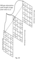
- Fig. 10 shows how a gas-absorption-path-length image is generated, in accordance with one or more embodiments, by compensating for water attenuation of infrared radiation.
- the sensitivity to detecting gas and thus contrast in the gas-absorption-path-length image is further improved by generating the gas-absorption-path-length image further based on a water infrared image 1030.
- a wavelength band C is determined to improve contrast in a generated gas-absorption-path-length image based on a predetermined water absorption spectrum, wherein wavelength band C includes at least a local maximum of the water absorption spectrum and preferably excludes both high absorption wavelength band A and low absorption wavelength band B.
- water wavelength band C is indicated in data comprised in infrared imaging system control data sent to the infrared imaging system.
- a water infrared image 1030 is captured by the first or second infrared imaging system 613, 614 triggered by the control data, wherein the water infrared image comprises intensity of infrared radiation within water wavelength band C.
- the processor 612 receives the water infrared image and generates an improved gas-absorption-path-length image based on a gas infrared image 910, a background infrared image 920 and the water infrared image 1030.
- a gas-absorption-path-length image is generated by combining pixel values comprised in the gas infrared image 910, pixel values comprised in the background infrared image 920 and pixel values comprised in the water infrared image 1030.
- the thermal imaging device might be moved in a way such that the offset, direction and rotation around the optical axis differ between a gas IR image and a background IR image.
- the orientation of optical axis of the first infrared imaging system 613 and the second infrared imaging system 614 might differ. This results in an optical phenomenon known as parallax distance error, parallax pointing error and parallax rotation error. Due to these parallax errors, the captured view of the real world scene might differ between IR images.
- the images In order to combine the gas infrared image and the background infrared image, the images must be adapted so that an adapted gas IR image and an adapted background IR image, representing the same part of the scene, is obtained, compensating for the different parallax errors and FOV size.
- This processing step is referred to as image registration or alignment of the first image and the second image, i.e. the process of transforming different sets of data into one coordinate system through a transform 940. Registration or alignment can be performed according to any method known to a skilled person in the art, e.g. intensity-based, feature-based registration using linear or elastic transformations.
- the captured IR image or gas-absorption-path-length image may be subjected to various imaging processing in order to improve the interpretability of the image before displaying it to a user.
- image processing is correction with IR temperature calibration data parameters, low pass filtering, registration of multiple successive IR image or gas infrared images and averaging to obtain an averaged IR image or gas infrared image or any other IR image or gas infrared image processing operation known to a person skilled in the art.
- an information visualization process referred to as false coloring or pseudo coloring is used to map image data values or pixel values of each pixel in animage, such as an IR image, quantified scene difference infrared image or gas-absorption-path-length image, to a palette used to present the corresponding pixel displayed on a display, e.g. using grey-scale or colors.
- a palette is typically a finite set of color or grey-scale representations selected from a color model for the display of images or visual representations of IR images, quantified scene difference infrared image or gas-absorption-path-length image, i.e. a pre-defined palette represents a finite set of grayscale or color values of a color model displayable on a display thereby making it visible to the human eye.
- Mapping of image data values of each pixel in an image, such as an IR image, quantified scene difference infrared image or gas-absorption-path-length image, to a palette used to present the corresponding pixel of a visual representation of said image displayed on a display is typically performed by applying a pre-determined relation.
- Such a pre-determined relation typically describes a mapping from image data values or pixel values to said pre-defined palette, e.g. a palette index value with an associated color or grey-scale representation selected from a color model.
- the gas IR image, quantified scene difference infrared image or gas-absorption-path-length image is typically displayed to an intended user based on the image data values or pixel values of each pixel in an image, such as an IR image, quantified scene difference infrared image or gas-absorption-path-length image.
- IR temperature calibration data parameters a predefined palette representing a finite set of grayscale or color values of a color model displayable on a display and a pre-determined relation describing a mapping from infrared image data values or gas-absorption-path-length image pixel values to said pre-defined palette.
- FIG. 11 there is shown an illustration of a camera in a system and method in accordance with one or more embodiments.
- images are generated used to quantify leaking gas.
- One camera detector will be filtered to a high absorption wavelength band A where the gas has strong absorption lines or high absorption of infrared radiation in the absorption spectrum, so that the camera will change signal when gas is present in the image.
- the other camera will be filtered to a low absorption wavelength band B where the gas has very weak or in this case almost no absorption lines or low absorption of infrared radiation in the absorption spectrum. In this manner the camera is used as a reference to see the background temperature without gas.
- By taking the temperature difference between images from camera filtered to detect high absorption wavelength A and low absorption wavelength B only the gas will be visible and other phenomenon but gas will be reduced.
- a model to optimally choose filter 710,720 positions or filter tunings with regard to signal and noise affected by these filter 710,720, in accordance with one or more embodiments, is explained as follows.
- the signal S is calculated by taking the exitance or measured emission of infrared radiation from the object, W obj , added with the exitance or measured emission of infrared radiation from the background, W bg .
- the signal S is calculated by taking the exitance from the object, W obj , added with the exitance from the background, W bg .
- W bg 1 ⁇ sin 2 ⁇ ⁇ M T cam ⁇ R det ⁇ + sin 2 ⁇ ⁇ M T filter ⁇ R det ⁇ 1 ⁇ ⁇ filter
- NETD Noise Equivalent Temperature Difference
- RMS noise ⁇ Unoise
- NETD the noise voltage measured as a Root Mean Square value of the cameras video channel and then converting it to the corresponding temperature difference.
- S'T is the derivative of the signal measured by the detector at a temperature T.
- S'T can be calculated. This derivative is evaluated at 30° C since this is a common temperature for measuring NETD. Since the detector noise, ⁇ Unoise, in Eq. 5 is assumed to be the same with and without filter 710,720 this is regarded as a constant.
- the filter 710,720 regions have to be much broader compared to cooled cameras because uncooled cameras have less sensitivity and a higher thermal noise contribution from the optical path to the sensor/detector 6132,6142.
- the filter 710,720 regions are quite broad not only absorption of gas as for example methane is present in the filter region but also water vapor. This means that water vapor has to be quantified as well as the gas, here methane.
- One way to achieve this is to have an additional third region spectrum filtered where only water vapor absorbs the radiation, e.g. wavelength band C 530. This is used in order quantify water vapor and then use this measurement to generate a composite spectrum to quantify methane.
- the other way is to measure the humidity in the air and the length to the background and assume the humidity is the same over this whole distance, and then calculate the concentration length of water vapor in ppm x m.
- the temperature of gas is needed and this is assumed be the same as the temperature in the air. This means that the air temperature has to be measured as well.
- the input values, to calculate signal difference with gas and no gas needed are the background temperature, the concentration length of water vapor, concentration length of methane gas and the temperature of the gas. With two different cameras that has different gain and offset values it is important to normalize the outputs so that the cameras will measure the same temperature.
- cuton or lower endpoint 5101 of high absorption wavelength band A and cutoff or higher endpoint 5102 of high absorption wavelength band A the influence of the gas can be optimized with regard to NETD and signal difference.
- Both the ratio between gas and no gas, and difference in signal were simulated with the motivation that theoretically the signal difference should be maximized without regard for emissivity change.
- the ratio between gas and no gas should be high because when using two cameras the normalization between the signals won't be perfect and result in a ratio difference.
- the chosen simulated cuton wavelengths range from 6 -7.8 ⁇ m and cutoff from 8-9.6 ⁇ m with 0.2pm steps. This is because the methane absorption peak is centered around 7.7um and the band pass filter 710,720 should be close to this absorption peak.
- Fig. 12 shows the resulting signal with changing filter 710,720 cuton and cutoff, i.e. lower endpoint and higher endpoint of a wavelength band, from a cutoff at 8 ⁇ m 710 to a cutoff at 9.6 ⁇ m 718.
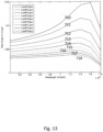
- Figure 13 shows the simulated signal gas or no gas ratio with and without methane gas in the simulation.
- the ratio of the signal will decrease with increasing bandwidth of the band pass filter, thus the wavelength band from a cutoff at 8 ⁇ m 710 to a cutoff at 9.6 um 718., although the signal difference will remain constant.
- the cuton wavelength goes up to 7.8 ⁇ m to show the decrease in signal difference as the cuton exceeds the absorption peak.
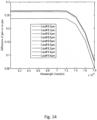
- Figure 14 shows the simulated signal difference with and without methane gas in the simulation.
- the ratio of the signal will decrease with increasing bandwidth of the band pass filter, thus the wavelength band from a cutoff at 8 ⁇ m to a cutoff at 9.6 ⁇ m, although the signal difference will remain constant.
- the cuton wavelength goes up to 7.8 ⁇ m to show the decrease in signal difference as the cuton exceeds the absorption peak.
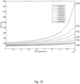
- Figure 15 shows an embodiment of the disclosure, where simulated NETD with changing filter band-pass bandwidth from a cutoff at 8 ⁇ m 710 to a cutoff at 9.6 ⁇ m 718. As can be seen the noise NETD is increased with decreasing filter bandwidth.
- the filter positions are simulated with a cutoff at 15 ⁇ m to simulate the cutoff of the camera system response and cuton ranging from 8um to 10.5um because this is where the absorption of methane will decrease to a limit where no absorption is present. This is shown in figure 16 .
- Fig. 16 Shows an embodiment of the invention where a simulation of ratio of gas vs no gas for changing cuton and a fixed cutoff at 15 ⁇ m.
- the methane concentration length used for this simulation is 1*107ppmm.
- the chosen cuton wavelength is 9.2um since there's very low absorption ratio for this cuton wavelength when simulation for a very concentrated and big gas cloud.
- Fig 17 shows various embodiments of the Gas-Quantifying Relation 180 of the present disclosure, e.g. in table 1-4.
- Gas-Quantifying Relation 180 is determined. This was done with known background temperature and gas temperature.
- the blackbody used as background was set to 70°C.
- the gas cell was measured with the camera to realize the gas temperature.
- the background temperature was measured to 79.4 ⁇ 0.1°C and the gas cell was measured to 30.9 ⁇ 0.2°C. This gave simulated values for the temperature with regard to gas absorption.
- Table 1- Simulated temperatures for different concentration-lengths for the BP filter.
- Measured temperatures for different gas concentration-lengths are presented below, with their calculated concentration lengths and known concentration lengths. Table 2 - Measured temperatures with calculated concentration-lengths compared to known concentration-length for the BP filter.
- Known concentration-length CL K Measured temperature T Measured concentration-length CL M CL M/ CL K 5 000 ppmm 68.7°C 9 090 ppmm 1.82 10 000 ppmm 66.7°C 17 190 ppmm 1.72 20 000 ppmm 63.8°C 34 270 ppmm 1.71 30 000 ppmm 61.7°C 52 020 ppmm 1.73 60 000 ppmm 57.9°C 102 180 ppmm 1.70 120 000 ppmm 53.7°C 201 630 ppmm 1.68
- Known concentration-length CLK Measured temperature T Measured Table 4 - Measured temperatures with calculated concentration-lengths compared to known concentration-length for the LP7000 filter.
- Known concentration-length CL K Measured temperature T Measured concentration-length CL M CL M/ CL K 5 000 ppmm 66.7°C 48 630 ppmm 9.73 10 000 ppmm 66.1°C 72 860 ppmm 7.29 20 000 ppmm 64.9°C 156 040 ppmm 7.80 30 000 ppmm 64.5°C 198 770 ppmm 6.63 60 000 ppmm 63.2°C 416 940 ppmm 6.95 120 000 ppmm 61.9°C 811 570 ppmm 6.76
- the processor of described thermal imaging devices is, in accordance with one or more embodiments, configured to perform a selection of any or all of the method steps described herein that are associated with processing of captured IR images or gas-absorption-path-length images comprising image data values or pixel values, such as selection of data values/pixel values, mapping of temperature values associated with the data values/pixel values to color and/or grayscale values, assigning each pixel of a frame of IR data values a representation value from a preselected color model, e.g. based on the associated temperature value of said pixel, and other operations described herein.
- a computer program product comprising code portions adapted to control a processor to perform any of the steps or functions of any of the embodiments described herein.
- Software in accordance with the present disclosure can be stored in non-transitory form on one or more machine-readable mediums. It is also contemplated that software identified herein can be implemented using one or more general purpose or specific purpose computers and/or computer systems, networked and/or otherwise.
- one or more embodiments provided by the present disclosure can be implemented using hardware, software, or combinations of hardware and software.
- the various hardware components and/or software components set forth herein can be combined into composite components comprising software, hardware, and/or both.
- the various hardware components and/or software components set forth herein can be separated into sub-components comprising software, hardware, or both.
- software components can be implemented as hardware components, and vice-versa.
- the ordering of various steps described herein can be changed, combined into composite steps, and/or separated into sub-steps to provide features described herein.
Landscapes
- Physics & Mathematics (AREA)
- Spectroscopy & Molecular Physics (AREA)
- General Physics & Mathematics (AREA)
- Chemical & Material Sciences (AREA)
- Life Sciences & Earth Sciences (AREA)
- Analytical Chemistry (AREA)
- Biochemistry (AREA)
- General Health & Medical Sciences (AREA)
- Health & Medical Sciences (AREA)
- Immunology (AREA)
- Pathology (AREA)
- Engineering & Computer Science (AREA)
- Theoretical Computer Science (AREA)
- Radiation Pyrometers (AREA)
- Investigating Or Analysing Materials By Optical Means (AREA)
- Transforming Light Signals Into Electric Signals (AREA)
Claims (10)
- Procédé de quantification de gaz dans l'imagerie d'une scène ayant un arrière-plan et une occurrence possible de gaz, ledit procédé comprenant :l'obtention d'une image infrarouge de gaz représentant un rayonnement infrarouge à l'intérieur d'une bande de longueurs d'onde de haute absorption A pour le gaz émis depuis la scène ;l'obtention d'une image infrarouge d'arrière-plan représentant un rayonnement infrarouge à l'intérieur d'une bande de longueurs d'onde de basse absorption B pour ledit gaz émis depuis la scène ;la génération d'une image de longueur de voie d'absorption de gaz en tant qu'une image infrarouge de différence de scène sur la base de l'image infrarouge de gaz et de l'image infrarouge d'arrière-plan de scène ; etla génération d'une image infrarouge de différence de scène quantifiée sur la base de l'image infrarouge de différence de scène et d'une relation de quantification de gaz, GQR, prédéfinie.
- Procédé selon la revendication 1, dans lequel la relation de quantification de gaz décrit des relations entre des valeurs de pixels d'image infrarouge de différence de scène et des valeurs de pixels d'image infrarouge de différence de scène quantifiée sous la forme d'un produit de longueur de concentration exprimé en parties par million * mètre ou ppm * m.
- Procédé selon la revendication 2, dans lequel la relation de quantification de gaz est générée par :la mesure d'un premier ensemble de valeurs de pixels d'image infrarouge de différence de scène quantifiée sur la base d'une concentration de gaz connue, d'une longueur de voie d'absorption de gaz, d'une température de gaz, et d'une température d'arrière-plan ; etl'expansion dudit premier ensemble en un second ensemble plus grand par l'application de techniques d'ajustement de courbe au premier ensemble de valeurs de pixels d'image infrarouge de différence de scène quantifiée.
- Procédé selon la revendication 1, comprenant en outre :la détermination de la bande de longueurs d'onde de haute absorption A et de la bande de longueurs d'onde de basse absorption B sur la base d'un bruit d'image estimé, d'un spectre d'absorption prédéterminé du gaz, d'une température de gaz estimée, et d'une température d'arrière-plan estimée, dans lequel la bande de longueurs d'onde de haute absorption A inclut une bande de longueurs d'onde d'absorption G du spectre d'absorption prédéterminé, et dans lequel la bande de longueurs d'onde de basse absorption B chevauche au moins partiellement la bande de longueurs d'onde de haute absorption A ;la génération de données de commande de système d'imagerie infrarouge pour commander à un système d'imagerie infrarouge d'acquérir l'image infrarouge de gaz de la scène et l'image infrarouge d'arrière-plan de la scène.
- Procédé selon la revendication 4, dans lequel le bruit d'image estimé comprend une différence de température équivalente de bruit, dans lequel les valeurs de pixels d'image infrarouge de différence de scène quantifiée comprennent des valeurs de température, par exemple en degrés Celsius ou Kelvin.
- Procédé selon la revendication 5, dans lequel la bande de longueurs d'onde de haute absorption A est déterminée avec un point d'extrémité inférieur dans l'intervalle de [6 à 7,8 µm] et dans lequel la bande de longueurs d'onde A est déterminée avec un point d'extrémité supérieur dans l'intervalle de [8 à 9,6 µm].
- Procédé selon la revendication 1, comprenant en outre :la détermination d'une bande de longueurs d'onde liée à l'eau C sur la base d'un spectre d'absorption d'eau prédéterminé, dans lequel la bande de longueurs d'onde liée à l'eau C inclut au moins un maximum local du spectre d'absorption d'eau prédéterminé et exclut la bande de longueurs d'onde de haute absorption A et la bande de longueurs d'onde de basse absorption B ;la génération de données de commande de système d'imagerie infrarouge pour commander à un système d'imagerie infrarouge d'acquérir une image infrarouge d'eau de la scène, dans lequel l'image infrarouge d'eau représente un rayonnement infrarouge à l'intérieur de la bande de longueurs d'onde liée à l'eau C émis depuis la scène ;dans lequel l'image infrarouge de différence de scène quantifiée est générée en outre sur la base de l'image infrarouge d'eau.
- Dispositif d'imagerie thermique permettant la quantification de gaz dans l'imagerie d'une scène ayant un arrière-plan et une occurrence possible de gaz, ledit dispositif comprenant un système d'imagerie infrarouge (IR), une mémoire et un processeur apte à effectuer les étapes de procédé selon l'une quelconque des revendications 1 à 7.
- Support lisible par ordinateur permettant la quantification de gaz dans l'imagerie d'une scène ayant un arrière-plan et une occurrence possible de gaz, sur lequel sont mémorisées :des informations non transitoires pour effectuer un procédé selon l'une quelconque des revendications 1 à 7 ;
et/oudes informations non transitoires configurées pour commander à un processeur/une unité de traitement d'effectuer les étapes selon l'une quelconque des revendications 1 à 7. - Produit de programme informatique permettant la quantification de gaz dans l'imagerie d'une scène ayant un arrière-plan et une occurrence possible de gaz, comprenant des portions de code aptes à commander à un processeur d'effectuer les étapes selon l'une quelconque des revendications 1 à 7.
Applications Claiming Priority (2)
| Application Number | Priority Date | Filing Date | Title |
|---|---|---|---|
| US201562127264P | 2015-03-02 | 2015-03-02 | |
| PCT/EP2016/000363 WO2016138991A1 (fr) | 2015-03-02 | 2016-03-02 | Quantification de gaz en imagerie de gaz optique passive |
Publications (2)
| Publication Number | Publication Date |
|---|---|
| EP3265996A1 EP3265996A1 (fr) | 2018-01-10 |
| EP3265996B1 true EP3265996B1 (fr) | 2024-07-17 |
Family
ID=55953097
Family Applications (1)
| Application Number | Title | Priority Date | Filing Date |
|---|---|---|---|
| EP16721356.0A Active EP3265996B1 (fr) | 2015-03-02 | 2016-03-02 | Quantification de gaz en imagerie de gaz optique passive |
Country Status (4)
| Country | Link |
|---|---|
| US (1) | US10416076B2 (fr) |
| EP (1) | EP3265996B1 (fr) |
| CN (1) | CN107407634B (fr) |
| WO (1) | WO2016138991A1 (fr) |
Families Citing this family (30)
| Publication number | Priority date | Publication date | Assignee | Title |
|---|---|---|---|---|
| JP6344533B2 (ja) * | 2015-12-15 | 2018-06-20 | コニカミノルタ株式会社 | ガス濃度厚み積測定装置、ガス濃度厚み積測定方法、ガス濃度厚み積測定プログラム、及び、ガス濃度厚み積測定プログラムを記録したコンピュータ読み取り可能な記録媒体 |
| US10274423B2 (en) * | 2016-01-21 | 2019-04-30 | Konica Minolta, Inc. | Gas detection device, gas detection method, and gas detection program |
| WO2017150565A1 (fr) * | 2016-03-03 | 2017-09-08 | コニカミノルタ株式会社 | Dispositif d'estimation de position de fuite de gaz, procédé d'estimation de position de fuite de gaz, et programme d'estimation de position de fuite de gaz |
| CA3041100A1 (fr) | 2016-10-21 | 2018-04-26 | Rebellion Photonics, Inc. | Systeme d'imagerie a gaz |
| US10400583B1 (en) * | 2016-12-22 | 2019-09-03 | Petra Analytics, Llc | Methods and systems for spatial change indicator analysis |
| WO2018183973A1 (fr) * | 2017-03-31 | 2018-10-04 | Flir Systems Ab | Systèmes et procédés d'imagerie de gaz |
| US10234380B1 (en) * | 2017-09-29 | 2019-03-19 | Konica Minolta Laboratory U.S.A., Inc. | Background radiance estimation and gas concentration-length quantification method for optical gas imaging camera |
| US10925208B2 (en) | 2017-10-31 | 2021-02-23 | Deere & Company | System and method for monitioring vapor concentrations |
| CN111527397B (zh) | 2017-11-09 | 2023-11-17 | 逆转光子公司 | 红外ir成像系统及其光学窗口遮蔽检测方法 |
| WO2019133795A1 (fr) * | 2017-12-29 | 2019-07-04 | Flir Systems Ab | Réseau de capteurs infrarouges comprenant des capteurs configurés pour différentes réponses spectrales |
| WO2019164578A2 (fr) * | 2018-01-03 | 2019-08-29 | Flir Systems Ab | Détermination dynamique de valeurs radiométriques à l'aide de systèmes et de procédés de réseau de capteurs à bandes multiples |
| US10684216B2 (en) * | 2018-03-30 | 2020-06-16 | Konica Minolta Laboratory U.S.A., Inc. | Multi-spectral gas quantification and differentiation method for optical gas imaging camera |
| US11869243B2 (en) * | 2018-05-30 | 2024-01-09 | Araani Nv | Method and system for detecting heating |
| WO2020131318A1 (fr) | 2018-12-20 | 2020-06-25 | Flir Systems Ab | Systèmes et procédés de filtre de lentille gazeuse |
| US11200697B2 (en) | 2018-12-20 | 2021-12-14 | Flir Systems Ab | Infrared camera ambient temperature calibration systems and methods |
| WO2020247664A1 (fr) | 2019-06-07 | 2020-12-10 | Honeywell International Inc. | Procédés et systèmes permettant d'analyser des images d'un brûleur de torche |
| US11513004B2 (en) | 2019-08-08 | 2022-11-29 | Apple Inc. | Terahertz spectroscopy and imaging in dynamic environments |
| US11099072B2 (en) * | 2019-08-08 | 2021-08-24 | Apple Inc. | Terahertz spectroscopy and imaging in dynamic environments with spectral response enhancements |
| US11555792B2 (en) | 2019-08-08 | 2023-01-17 | Apple Inc. | Terahertz spectroscopy and imaging in dynamic environments with performance enhancements using ambient sensors |
| CN111127403A (zh) * | 2019-12-06 | 2020-05-08 | 东莞理工学院 | 一种基于opencv的氡气浓度检测方法 |
| CN113125341B (zh) * | 2019-12-30 | 2023-09-29 | 上海禾赛科技有限公司 | 基于多光谱成像技术的气体遥测方法和装置 |
| US11386530B2 (en) | 2020-02-26 | 2022-07-12 | Flir Systems Ab | Digital filter for turbulence reduction and gas detection in thermal images |
| IL275524B (en) * | 2020-06-18 | 2021-12-01 | Elbit Systems C4I & Cyber Ltd | System and method for measuring parameters without contact |
| CN112307267B (zh) * | 2020-06-29 | 2023-07-04 | 数量级(上海)信息技术有限公司 | 一种泄漏气体的浓度量化系统及方法 |
| US12455193B2 (en) | 2021-08-25 | 2025-10-28 | Flir Systems Ab | Variable sensitivity in infrared imaging systems and methods |
| WO2023101923A1 (fr) | 2021-12-03 | 2023-06-08 | Flir Systems Ab | Détermination de seuil de détection pour systèmes et procédés d'imagerie infrarouge |
| WO2023105856A1 (fr) * | 2021-12-10 | 2023-06-15 | コニカミノルタ株式会社 | Dispositif de mesure de concentration de gaz, procédé de mesure de concentration de gaz et programme |
| US11927485B2 (en) | 2021-12-17 | 2024-03-12 | Rebellion Photonics, Inc. | Systems, methods, and computer program products for detection limit determinations for hyperspectral imaging |
| CN116840181A (zh) * | 2023-06-30 | 2023-10-03 | 中国科学院长春光学精密机械与物理研究所 | 基于辐射透射通道切换的气体浓度反演方法 |
| CN117968863B (zh) * | 2024-03-27 | 2024-06-14 | 杭州微影软件有限公司 | 红外测温方法、装置、设备及存储介质 |
Family Cites Families (11)
| Publication number | Priority date | Publication date | Assignee | Title |
|---|---|---|---|---|
| US5430293A (en) * | 1991-10-08 | 1995-07-04 | Osaka Gas Co., Ltd. | Gas visualizing apparatus and method for detecting gas leakage from tanks or piping |
| SE9904836L (sv) * | 1999-12-28 | 2001-06-29 | Jonas Sandsten | Kvantitativ avbildning av gasemissioner utnyttjande optisk teknik |
| FR2832799B1 (fr) * | 2001-11-23 | 2006-11-03 | Bertin Technologies Sa | Procedure de detection optique de gaz a distance |
| WO2005001409A2 (fr) * | 2003-06-11 | 2005-01-06 | Furry Brothers, Llc | Systemes et procedes de mise en oeuvre d'inspections et de detection de fuites chimiques faisant appel a un systeme de camera infrarouge |
| US6822742B1 (en) * | 2003-12-19 | 2004-11-23 | Eastman Kodak Company | System and method for remote quantitative detection of fluid leaks from a natural gas or oil pipeline |
| DE102004028433B4 (de) * | 2004-06-14 | 2006-08-31 | Danfoss A/S | IR-Sensor, insbesondere CO2-Sensor |
| JP4209877B2 (ja) * | 2005-09-01 | 2009-01-14 | ホーチキ株式会社 | ガス監視装置 |
| ES2649488T3 (es) * | 2008-07-24 | 2018-01-12 | Massachusetts Institute Of Technology | Sistemas y métodos para la obtención de imágenes usando absorción |
| EP2590138B1 (fr) * | 2011-11-07 | 2019-09-11 | Flir Systems AB | Agencements de visualisation de gaz, dispositifs et procédés |
| CN103217397A (zh) * | 2013-01-23 | 2013-07-24 | 山西省电力公司晋城供电分公司 | 基于红外图像处理的sf6气体检测方法 |
| US9726543B2 (en) * | 2015-02-18 | 2017-08-08 | Providence Photonics, Llc | Apparatus and method for validating leak survey results |
-
2016
- 2016-03-02 WO PCT/EP2016/000363 patent/WO2016138991A1/fr not_active Ceased
- 2016-03-02 CN CN201680013555.7A patent/CN107407634B/zh active Active
- 2016-03-02 EP EP16721356.0A patent/EP3265996B1/fr active Active
-
2017
- 2017-08-31 US US15/693,007 patent/US10416076B2/en active Active
Also Published As
| Publication number | Publication date |
|---|---|
| CN107407634A (zh) | 2017-11-28 |
| US20170363541A1 (en) | 2017-12-21 |
| CN107407634B (zh) | 2020-11-06 |
| WO2016138991A1 (fr) | 2016-09-09 |
| US10416076B2 (en) | 2019-09-17 |
| EP3265996A1 (fr) | 2018-01-10 |
Similar Documents
| Publication | Publication Date | Title |
|---|---|---|
| EP3265996B1 (fr) | Quantification de gaz en imagerie de gaz optique passive | |
| EP3265782B1 (fr) | Imagerie de gaz par infrarouge passif basée sur la bande de longueur d'onde | |
| US20240094118A1 (en) | Gas leak emission quantification with a gas cloud imager | |
| US11249016B2 (en) | Wavelength band based passive infrared gas imaging | |
| US9726543B2 (en) | Apparatus and method for validating leak survey results | |
| CN112484861A (zh) | 一种红外测温方法、装置、设备及存储介质 | |
| US12105020B2 (en) | Gas lens filter systems and methods | |
| CN105203465B (zh) | 一种超光谱红外成像气体监测装置及其监测方法 | |
| US20100265987A2 (en) | Method and Apparatus for Measuring the Temperature of a Sheet Material | |
| US11373302B2 (en) | Thermal camera, and method thereof for early diagnosis of infectious diseases | |
| CN110914670A (zh) | 气体成像系统和方法 | |
| CN118758503B (zh) | 基于单探测器的多组分绝缘气体泄漏红外检测系统及方法 | |
| JP6750672B2 (ja) | ガス観測方法 | |
| CN108700462B (zh) | 无移动部件的双光谱成像器及其漂移纠正方法 | |
| Soleimanijavid et al. | Smart Low-cost Thermal Imaging Acquisition Towards Personal Comfort Prediction | |
| Soldani | Infrared signature: Theory and example of practical measurement methods | |
| Liao et al. | Matched Filtering based on Background Radiance Estimation for Gas Detection with Thermal Infrared Hyperspectral Imaging | |
| Sun et al. | Assembling, Calibration, and Application of a Multispectral Polarimetric Vision System for Small UAVs | |
| CN120751221A (zh) | 一种手机外置热成像仪的成像方法、系统及热成像装置 | |
| Chamberland et al. | Performance of a field-portable imaging FTS | |
| Daly et al. | Precision radiometric surface temperature (PRST) sensor | |
| Roberts et al. | High spatial resolution LWIR hyperspectral sensor | |
| Thériault et al. | Imaging FTS for Hyperspectral Polarization Sensing in the LWIR: Application to Liquid Detection | |
| Zhou et al. | Wavelength calibration of imaging spectrometer using atmospheric absorption features | |
| Lane et al. | Detection of aircraft exhaust in hyperspectral image data |
Legal Events
| Date | Code | Title | Description |
|---|---|---|---|
| STAA | Information on the status of an ep patent application or granted ep patent |
Free format text: STATUS: THE INTERNATIONAL PUBLICATION HAS BEEN MADE |
|
| PUAI | Public reference made under article 153(3) epc to a published international application that has entered the european phase |
Free format text: ORIGINAL CODE: 0009012 |
|
| STAA | Information on the status of an ep patent application or granted ep patent |
Free format text: STATUS: REQUEST FOR EXAMINATION WAS MADE |
|
| 17P | Request for examination filed |
Effective date: 20170831 |
|
| AK | Designated contracting states |
Kind code of ref document: A1 Designated state(s): AL AT BE BG CH CY CZ DE DK EE ES FI FR GB GR HR HU IE IS IT LI LT LU LV MC MK MT NL NO PL PT RO RS SE SI SK SM TR |
|
| AX | Request for extension of the european patent |
Extension state: BA ME |
|
| DAV | Request for validation of the european patent (deleted) | ||
| DAX | Request for extension of the european patent (deleted) | ||
| GRAP | Despatch of communication of intention to grant a patent |
Free format text: ORIGINAL CODE: EPIDOSNIGR1 |
|
| STAA | Information on the status of an ep patent application or granted ep patent |
Free format text: STATUS: GRANT OF PATENT IS INTENDED |
|
| RAP1 | Party data changed (applicant data changed or rights of an application transferred) |
Owner name: FLIR SYSTEMS AB |
|
| INTG | Intention to grant announced |
Effective date: 20191007 |
|
| 19A | Proceedings stayed before grant |
Effective date: 20191217 |
|
| 19F | Resumption of proceedings before grant (after stay of proceedings) |
Effective date: 20240102 |
|
| GRAS | Grant fee paid |
Free format text: ORIGINAL CODE: EPIDOSNIGR3 |
|
| GRAA | (expected) grant |
Free format text: ORIGINAL CODE: 0009210 |
|
| STAA | Information on the status of an ep patent application or granted ep patent |
Free format text: STATUS: THE PATENT HAS BEEN GRANTED |
|
| AK | Designated contracting states |
Kind code of ref document: B1 Designated state(s): AL AT BE BG CH CY CZ DE DK EE ES FI FR GB GR HR HU IE IS IT LI LT LU LV MC MK MT NL NO PL PT RO RS SE SI SK SM TR |
|
| REG | Reference to a national code |
Ref country code: GB Ref legal event code: FG4D |
|
| REG | Reference to a national code |
Ref country code: CH Ref legal event code: EP |
|
| REG | Reference to a national code |
Ref country code: DE Ref legal event code: R096 Ref document number: 602016088431 Country of ref document: DE |
|
| REG | Reference to a national code |
Ref country code: IE Ref legal event code: FG4D |
|
| REG | Reference to a national code |
Ref country code: LT Ref legal event code: MG9D |
|
| REG | Reference to a national code |
Ref country code: NL Ref legal event code: MP Effective date: 20240717 |
|
| PG25 | Lapsed in a contracting state [announced via postgrant information from national office to epo] |
Ref country code: PT Free format text: LAPSE BECAUSE OF FAILURE TO SUBMIT A TRANSLATION OF THE DESCRIPTION OR TO PAY THE FEE WITHIN THE PRESCRIBED TIME-LIMIT Effective date: 20241118 |
|
| REG | Reference to a national code |
Ref country code: AT Ref legal event code: MK05 Ref document number: 1704864 Country of ref document: AT Kind code of ref document: T Effective date: 20240717 |
|
| PG25 | Lapsed in a contracting state [announced via postgrant information from national office to epo] |
Ref country code: NL Free format text: LAPSE BECAUSE OF FAILURE TO SUBMIT A TRANSLATION OF THE DESCRIPTION OR TO PAY THE FEE WITHIN THE PRESCRIBED TIME-LIMIT Effective date: 20240717 |
|
| PG25 | Lapsed in a contracting state [announced via postgrant information from national office to epo] |
Ref country code: PT Free format text: LAPSE BECAUSE OF FAILURE TO SUBMIT A TRANSLATION OF THE DESCRIPTION OR TO PAY THE FEE WITHIN THE PRESCRIBED TIME-LIMIT Effective date: 20241118 Ref country code: NL Free format text: LAPSE BECAUSE OF FAILURE TO SUBMIT A TRANSLATION OF THE DESCRIPTION OR TO PAY THE FEE WITHIN THE PRESCRIBED TIME-LIMIT Effective date: 20240717 |
|
| PG25 | Lapsed in a contracting state [announced via postgrant information from national office to epo] |
Ref country code: NO Free format text: LAPSE BECAUSE OF FAILURE TO SUBMIT A TRANSLATION OF THE DESCRIPTION OR TO PAY THE FEE WITHIN THE PRESCRIBED TIME-LIMIT Effective date: 20241017 |
|
| PG25 | Lapsed in a contracting state [announced via postgrant information from national office to epo] |
Ref country code: PL Free format text: LAPSE BECAUSE OF FAILURE TO SUBMIT A TRANSLATION OF THE DESCRIPTION OR TO PAY THE FEE WITHIN THE PRESCRIBED TIME-LIMIT Effective date: 20240717 Ref country code: FI Free format text: LAPSE BECAUSE OF FAILURE TO SUBMIT A TRANSLATION OF THE DESCRIPTION OR TO PAY THE FEE WITHIN THE PRESCRIBED TIME-LIMIT Effective date: 20240717 Ref country code: GR Free format text: LAPSE BECAUSE OF FAILURE TO SUBMIT A TRANSLATION OF THE DESCRIPTION OR TO PAY THE FEE WITHIN THE PRESCRIBED TIME-LIMIT Effective date: 20241018 |
|
| PG25 | Lapsed in a contracting state [announced via postgrant information from national office to epo] |
Ref country code: BG Free format text: LAPSE BECAUSE OF FAILURE TO SUBMIT A TRANSLATION OF THE DESCRIPTION OR TO PAY THE FEE WITHIN THE PRESCRIBED TIME-LIMIT Effective date: 20240717 |
|
| PG25 | Lapsed in a contracting state [announced via postgrant information from national office to epo] |
Ref country code: LV Free format text: LAPSE BECAUSE OF FAILURE TO SUBMIT A TRANSLATION OF THE DESCRIPTION OR TO PAY THE FEE WITHIN THE PRESCRIBED TIME-LIMIT Effective date: 20240717 |
|
| PG25 | Lapsed in a contracting state [announced via postgrant information from national office to epo] |
Ref country code: IS Free format text: LAPSE BECAUSE OF FAILURE TO SUBMIT A TRANSLATION OF THE DESCRIPTION OR TO PAY THE FEE WITHIN THE PRESCRIBED TIME-LIMIT Effective date: 20241117 Ref country code: AT Free format text: LAPSE BECAUSE OF FAILURE TO SUBMIT A TRANSLATION OF THE DESCRIPTION OR TO PAY THE FEE WITHIN THE PRESCRIBED TIME-LIMIT Effective date: 20240717 |
|
| PG25 | Lapsed in a contracting state [announced via postgrant information from national office to epo] |
Ref country code: HR Free format text: LAPSE BECAUSE OF FAILURE TO SUBMIT A TRANSLATION OF THE DESCRIPTION OR TO PAY THE FEE WITHIN THE PRESCRIBED TIME-LIMIT Effective date: 20240717 |
|
| PG25 | Lapsed in a contracting state [announced via postgrant information from national office to epo] |
Ref country code: ES Free format text: LAPSE BECAUSE OF FAILURE TO SUBMIT A TRANSLATION OF THE DESCRIPTION OR TO PAY THE FEE WITHIN THE PRESCRIBED TIME-LIMIT Effective date: 20240717 Ref country code: RS Free format text: LAPSE BECAUSE OF FAILURE TO SUBMIT A TRANSLATION OF THE DESCRIPTION OR TO PAY THE FEE WITHIN THE PRESCRIBED TIME-LIMIT Effective date: 20241017 |
|
| PG25 | Lapsed in a contracting state [announced via postgrant information from national office to epo] |
Ref country code: RS Free format text: LAPSE BECAUSE OF FAILURE TO SUBMIT A TRANSLATION OF THE DESCRIPTION OR TO PAY THE FEE WITHIN THE PRESCRIBED TIME-LIMIT Effective date: 20241017 Ref country code: PL Free format text: LAPSE BECAUSE OF FAILURE TO SUBMIT A TRANSLATION OF THE DESCRIPTION OR TO PAY THE FEE WITHIN THE PRESCRIBED TIME-LIMIT Effective date: 20240717 Ref country code: NO Free format text: LAPSE BECAUSE OF FAILURE TO SUBMIT A TRANSLATION OF THE DESCRIPTION OR TO PAY THE FEE WITHIN THE PRESCRIBED TIME-LIMIT Effective date: 20241017 Ref country code: LV Free format text: LAPSE BECAUSE OF FAILURE TO SUBMIT A TRANSLATION OF THE DESCRIPTION OR TO PAY THE FEE WITHIN THE PRESCRIBED TIME-LIMIT Effective date: 20240717 Ref country code: IS Free format text: LAPSE BECAUSE OF FAILURE TO SUBMIT A TRANSLATION OF THE DESCRIPTION OR TO PAY THE FEE WITHIN THE PRESCRIBED TIME-LIMIT Effective date: 20241117 Ref country code: HR Free format text: LAPSE BECAUSE OF FAILURE TO SUBMIT A TRANSLATION OF THE DESCRIPTION OR TO PAY THE FEE WITHIN THE PRESCRIBED TIME-LIMIT Effective date: 20240717 Ref country code: GR Free format text: LAPSE BECAUSE OF FAILURE TO SUBMIT A TRANSLATION OF THE DESCRIPTION OR TO PAY THE FEE WITHIN THE PRESCRIBED TIME-LIMIT Effective date: 20241018 Ref country code: FI Free format text: LAPSE BECAUSE OF FAILURE TO SUBMIT A TRANSLATION OF THE DESCRIPTION OR TO PAY THE FEE WITHIN THE PRESCRIBED TIME-LIMIT Effective date: 20240717 Ref country code: ES Free format text: LAPSE BECAUSE OF FAILURE TO SUBMIT A TRANSLATION OF THE DESCRIPTION OR TO PAY THE FEE WITHIN THE PRESCRIBED TIME-LIMIT Effective date: 20240717 Ref country code: BG Free format text: LAPSE BECAUSE OF FAILURE TO SUBMIT A TRANSLATION OF THE DESCRIPTION OR TO PAY THE FEE WITHIN THE PRESCRIBED TIME-LIMIT Effective date: 20240717 Ref country code: AT Free format text: LAPSE BECAUSE OF FAILURE TO SUBMIT A TRANSLATION OF THE DESCRIPTION OR TO PAY THE FEE WITHIN THE PRESCRIBED TIME-LIMIT Effective date: 20240717 |
|
| PG25 | Lapsed in a contracting state [announced via postgrant information from national office to epo] |
Ref country code: RO Free format text: LAPSE BECAUSE OF FAILURE TO SUBMIT A TRANSLATION OF THE DESCRIPTION OR TO PAY THE FEE WITHIN THE PRESCRIBED TIME-LIMIT Effective date: 20240717 Ref country code: DK Free format text: LAPSE BECAUSE OF FAILURE TO SUBMIT A TRANSLATION OF THE DESCRIPTION OR TO PAY THE FEE WITHIN THE PRESCRIBED TIME-LIMIT Effective date: 20240717 Ref country code: SM Free format text: LAPSE BECAUSE OF FAILURE TO SUBMIT A TRANSLATION OF THE DESCRIPTION OR TO PAY THE FEE WITHIN THE PRESCRIBED TIME-LIMIT Effective date: 20240717 |
|
| REG | Reference to a national code |
Ref country code: DE Ref legal event code: R097 Ref document number: 602016088431 Country of ref document: DE |
|
| PG25 | Lapsed in a contracting state [announced via postgrant information from national office to epo] |
Ref country code: EE Free format text: LAPSE BECAUSE OF FAILURE TO SUBMIT A TRANSLATION OF THE DESCRIPTION OR TO PAY THE FEE WITHIN THE PRESCRIBED TIME-LIMIT Effective date: 20240717 |
|
| PG25 | Lapsed in a contracting state [announced via postgrant information from national office to epo] |
Ref country code: CZ Free format text: LAPSE BECAUSE OF FAILURE TO SUBMIT A TRANSLATION OF THE DESCRIPTION OR TO PAY THE FEE WITHIN THE PRESCRIBED TIME-LIMIT Effective date: 20240717 |
|
| PG25 | Lapsed in a contracting state [announced via postgrant information from national office to epo] |
Ref country code: SK Free format text: LAPSE BECAUSE OF FAILURE TO SUBMIT A TRANSLATION OF THE DESCRIPTION OR TO PAY THE FEE WITHIN THE PRESCRIBED TIME-LIMIT Effective date: 20240717 |
|
| PLBE | No opposition filed within time limit |
Free format text: ORIGINAL CODE: 0009261 |
|
| STAA | Information on the status of an ep patent application or granted ep patent |
Free format text: STATUS: NO OPPOSITION FILED WITHIN TIME LIMIT |
|
| 26N | No opposition filed |
Effective date: 20250422 |
|
| PG25 | Lapsed in a contracting state [announced via postgrant information from national office to epo] |
Ref country code: SE Free format text: LAPSE BECAUSE OF FAILURE TO SUBMIT A TRANSLATION OF THE DESCRIPTION OR TO PAY THE FEE WITHIN THE PRESCRIBED TIME-LIMIT Effective date: 20240717 |
|
| PG25 | Lapsed in a contracting state [announced via postgrant information from national office to epo] |
Ref country code: MC Free format text: LAPSE BECAUSE OF FAILURE TO SUBMIT A TRANSLATION OF THE DESCRIPTION OR TO PAY THE FEE WITHIN THE PRESCRIBED TIME-LIMIT Effective date: 20240717 |
|
| REG | Reference to a national code |
Ref country code: CH Ref legal event code: H13 Free format text: ST27 STATUS EVENT CODE: U-0-0-H10-H13 (AS PROVIDED BY THE NATIONAL OFFICE) Effective date: 20251024 |
|
| PG25 | Lapsed in a contracting state [announced via postgrant information from national office to epo] |
Ref country code: LU Free format text: LAPSE BECAUSE OF NON-PAYMENT OF DUE FEES Effective date: 20250302 |
|
| REG | Reference to a national code |
Ref country code: BE Ref legal event code: MM Effective date: 20250331 |
|
| PG25 | Lapsed in a contracting state [announced via postgrant information from national office to epo] |
Ref country code: BE Free format text: LAPSE BECAUSE OF NON-PAYMENT OF DUE FEES Effective date: 20250331 |
|
| PG25 | Lapsed in a contracting state [announced via postgrant information from national office to epo] |
Ref country code: CH Free format text: LAPSE BECAUSE OF NON-PAYMENT OF DUE FEES Effective date: 20250331 |
|
| PG25 | Lapsed in a contracting state [announced via postgrant information from national office to epo] |
Ref country code: IE Free format text: LAPSE BECAUSE OF NON-PAYMENT OF DUE FEES Effective date: 20250302 |
|
| PG25 | Lapsed in a contracting state [announced via postgrant information from national office to epo] |
Ref country code: IT Free format text: LAPSE BECAUSE OF FAILURE TO SUBMIT A TRANSLATION OF THE DESCRIPTION OR TO PAY THE FEE WITHIN THE PRESCRIBED TIME-LIMIT Effective date: 20240717 |
|
| PGFP | Annual fee paid to national office [announced via postgrant information from national office to epo] |
Ref country code: GB Payment date: 20260323 Year of fee payment: 11 |
|
| PGFP | Annual fee paid to national office [announced via postgrant information from national office to epo] |
Ref country code: DE Payment date: 20260313 Year of fee payment: 11 |
|
| PGFP | Annual fee paid to national office [announced via postgrant information from national office to epo] |
Ref country code: FR Payment date: 20260330 Year of fee payment: 11 |