EP3266116B1 - Procédé et appareil pour communiquer avec une antenne utilisateur - Google Patents
Procédé et appareil pour communiquer avec une antenne utilisateur Download PDFInfo
- Publication number
- EP3266116B1 EP3266116B1 EP16709504.1A EP16709504A EP3266116B1 EP 3266116 B1 EP3266116 B1 EP 3266116B1 EP 16709504 A EP16709504 A EP 16709504A EP 3266116 B1 EP3266116 B1 EP 3266116B1
- Authority
- EP
- European Patent Office
- Prior art keywords
- antenna
- aerial
- antennas
- ground
- signals
- Prior art date
- Legal status (The legal status is an assumption and is not a legal conclusion. Google has not performed a legal analysis and makes no representation as to the accuracy of the status listed.)
- Active
Links
Images





Classifications
-
- H—ELECTRICITY
- H04—ELECTRIC COMMUNICATION TECHNIQUE
- H04B—TRANSMISSION
- H04B7/00—Radio transmission systems, i.e. using radiation field
- H04B7/02—Diversity systems; Multi-antenna system, i.e. transmission or reception using multiple antennas
- H04B7/022—Site diversity; Macro-diversity
- H04B7/024—Co-operative use of antennas of several sites, e.g. in co-ordinated multipoint or co-operative multiple-input multiple-output [MIMO] systems
-
- G—PHYSICS
- G01—MEASURING; TESTING
- G01S—RADIO DIRECTION-FINDING; RADIO NAVIGATION; DETERMINING DISTANCE OR VELOCITY BY USE OF RADIO WAVES; LOCATING OR PRESENCE-DETECTING BY USE OF THE REFLECTION OR RERADIATION OF RADIO WAVES; ANALOGOUS ARRANGEMENTS USING OTHER WAVES
- G01S13/00—Systems using the reflection or reradiation of radio waves, e.g. radar systems; Analogous systems using reflection or reradiation of waves whose nature or wavelength is irrelevant or unspecified
- G01S13/88—Radar or analogous systems specially adapted for specific applications
- G01S13/95—Radar or analogous systems specially adapted for specific applications for meteorological use
- G01S13/955—Radar or analogous systems specially adapted for specific applications for meteorological use mounted on satellite
-
- G—PHYSICS
- G01—MEASURING; TESTING
- G01S—RADIO DIRECTION-FINDING; RADIO NAVIGATION; DETERMINING DISTANCE OR VELOCITY BY USE OF RADIO WAVES; LOCATING OR PRESENCE-DETECTING BY USE OF THE REFLECTION OR RERADIATION OF RADIO WAVES; ANALOGOUS ARRANGEMENTS USING OTHER WAVES
- G01S19/00—Satellite radio beacon positioning systems; Determining position, velocity or attitude using signals transmitted by such systems
- G01S19/38—Determining a navigation solution using signals transmitted by a satellite radio beacon positioning system
- G01S19/39—Determining a navigation solution using signals transmitted by a satellite radio beacon positioning system the satellite radio beacon positioning system transmitting time-stamped messages, e.g. GPS [Global Positioning System], GLONASS [Global Orbiting Navigation Satellite System] or GALILEO
- G01S19/42—Determining position
- G01S19/43—Determining position using carrier phase measurements, e.g. kinematic positioning; using long or short baseline interferometry
-
- G—PHYSICS
- G01—MEASURING; TESTING
- G01S—RADIO DIRECTION-FINDING; RADIO NAVIGATION; DETERMINING DISTANCE OR VELOCITY BY USE OF RADIO WAVES; LOCATING OR PRESENCE-DETECTING BY USE OF THE REFLECTION OR RERADIATION OF RADIO WAVES; ANALOGOUS ARRANGEMENTS USING OTHER WAVES
- G01S19/00—Satellite radio beacon positioning systems; Determining position, velocity or attitude using signals transmitted by such systems
- G01S19/38—Determining a navigation solution using signals transmitted by a satellite radio beacon positioning system
- G01S19/39—Determining a navigation solution using signals transmitted by a satellite radio beacon positioning system the satellite radio beacon positioning system transmitting time-stamped messages, e.g. GPS [Global Positioning System], GLONASS [Global Orbiting Navigation Satellite System] or GALILEO
- G01S19/42—Determining position
- G01S19/43—Determining position using carrier phase measurements, e.g. kinematic positioning; using long or short baseline interferometry
- G01S19/44—Carrier phase ambiguity resolution; Floating ambiguity; LAMBDA [Least-squares AMBiguity Decorrelation Adjustment] method
-
- G—PHYSICS
- G01—MEASURING; TESTING
- G01S—RADIO DIRECTION-FINDING; RADIO NAVIGATION; DETERMINING DISTANCE OR VELOCITY BY USE OF RADIO WAVES; LOCATING OR PRESENCE-DETECTING BY USE OF THE REFLECTION OR RERADIATION OF RADIO WAVES; ANALOGOUS ARRANGEMENTS USING OTHER WAVES
- G01S5/00—Position-fixing by co-ordinating two or more direction or position line determinations; Position-fixing by co-ordinating two or more distance determinations
- G01S5/02—Position-fixing by co-ordinating two or more direction or position line determinations; Position-fixing by co-ordinating two or more distance determinations using radio waves
- G01S5/10—Position of receiver fixed by co-ordinating a plurality of position lines defined by path-difference measurements, e.g. omega or decca systems
-
- H—ELECTRICITY
- H04—ELECTRIC COMMUNICATION TECHNIQUE
- H04B—TRANSMISSION
- H04B7/00—Radio transmission systems, i.e. using radiation field
- H04B7/02—Diversity systems; Multi-antenna system, i.e. transmission or reception using multiple antennas
- H04B7/04—Diversity systems; Multi-antenna system, i.e. transmission or reception using multiple antennas using two or more spaced independent antennas
- H04B7/0413—MIMO systems
- H04B7/0426—Power distribution
- H04B7/043—Power distribution using best eigenmode, e.g. beam forming or beam steering
-
- H—ELECTRICITY
- H04—ELECTRIC COMMUNICATION TECHNIQUE
- H04B—TRANSMISSION
- H04B7/00—Radio transmission systems, i.e. using radiation field
- H04B7/02—Diversity systems; Multi-antenna system, i.e. transmission or reception using multiple antennas
- H04B7/04—Diversity systems; Multi-antenna system, i.e. transmission or reception using multiple antennas using two or more spaced independent antennas
- H04B7/06—Diversity systems; Multi-antenna system, i.e. transmission or reception using multiple antennas using two or more spaced independent antennas at the transmitting station
- H04B7/0613—Diversity systems; Multi-antenna system, i.e. transmission or reception using multiple antennas using two or more spaced independent antennas at the transmitting station using simultaneous transmission
- H04B7/0615—Diversity systems; Multi-antenna system, i.e. transmission or reception using multiple antennas using two or more spaced independent antennas at the transmitting station using simultaneous transmission of weighted versions of same signal
- H04B7/0617—Diversity systems; Multi-antenna system, i.e. transmission or reception using multiple antennas using two or more spaced independent antennas at the transmitting station using simultaneous transmission of weighted versions of same signal for beam forming
-
- H—ELECTRICITY
- H04—ELECTRIC COMMUNICATION TECHNIQUE
- H04B—TRANSMISSION
- H04B7/00—Radio transmission systems, i.e. using radiation field
- H04B7/14—Relay systems
- H04B7/15—Active relay systems
- H04B7/185—Space-based or airborne stations; Stations for satellite systems
- H04B7/18502—Airborne stations
- H04B7/18504—Aircraft used as relay or high altitude atmospheric platform
Definitions
- the invention relates to aerial inter-antenna beamforming utilizing multiple phased-array antennas, which enables the delivery of information services, including telecommunications, earth observation, astronomical and positioning services. It also enables multiple conventional antennas to be used in a similar manner.
- High altitude platforms aircraft and lighter than air structures situated from 10 to 35 km altitude
- HAPS have been proposed to support a wide variety of applications. Areas of growing interest are for telecommunications, positioning, observation and other information services, and specifically the provision of high speed Internet, e-mail, telephony, televisual services, games, video on demand, mapping services and global positioning.
- Satellites possess several advantages over satellites as a result of operating much closer to the earth's surface, at typically around 20 km altitude.
- Geostationary satellites are situated at around 40,000 km altitude, and low earth orbit satellites are usually at around 600 km to 3000 km altitude. Satellites exist at lower altitudes but their lifetime is very limited with consequent economic impact.
- high altitude platforms are within the transmission range for standard mobile phones for signal power and signal latency. Any satellite is out of range for a normal terrestrial mobile phone network, operating without especially large or specialist antennas.
- High altitude platforms also avoid the rocket propelled launches needed for satellites, with their high acceleration and vibration, as well as high launch failure rates with their attendant impact on satellite cost. Payloads on high altitude platforms can be recovered easily and at modest cost compared to satellite payloads. Shorter development times and lower costs result from less demanding testing requirements.
- US patent 7,046,934 discloses a high altitude balloon for delivering information services in conjunction with a satellite.
- US 20040118969 A1 , WO 2005084156 A2 , US 5518205 A , US 2014/0252156 A1 disclose particular designs of high altitude aircraft.
- US 2002/0107034 A1 discloses a mobile communicating system including a user terminal and a plurality of satellites which transmit and receive a plurality of communication signals to and from the user terminal.
- US 2013/0070677 A1 discloses the use of aircrafts and a ground based beanforming facility wherein the aircafts carry antenna and can operate as an aggregated or distributed array.
- International application WO 00/14902 A2 discloses a network to enable wireless broadband communication services to provide connectivity between users anywhere on Earth that are both within and beyond a geographic area by utilizing millimeter and microwave carrier frequencies with wide bandwidths.
- Reliability, coverage and data capacity per unit ground area are critical performance criteria for mobile phone, device communication systems, earth observation and positioning services.
- Government regulators usually define the frequencies and bandwidth for use by systems transmitting electromagnetic radiation. The shorter the wavelength, the greater the data rates possible for a given fractional bandwidth, but the greater the attenuation through obstructions such as rain or walls, and has more limited diffraction which can be used to provide good coverage. These constraints result in the choice of carrier frequencies of between 0.7 and 5 GHz in most parts of the world with typically a 10 to 200 MHz bandwidth.
- HALE high altitude unmanned long endurance
- aerostats would need to carry large antenna(s) to distinguish between closely based transceivers on the ground.
- a larger diameter antenna leads to a smaller angular resolution of the system, hence the shorter the distance on the ground that the system can resolve.
- the resolution is determined by the "Rayleigh criterion" well known to those skilled in the art. The greater the antenna resolution, the higher the potential data rates per unit ground area are.
- Phased array digital "beamforming” (DBF) and multi beam horn (MBH) antennas have been considered for high altitude platforms in for example, R. Miura and M. Suzuki, “Preliminary Flight Test Program on Telecom and Broadcasting Using High Altitude Platform Stations," Wireless Pers. Commun., An Int'l. J., Kluwer Academic Publishers, vol. 24, no. 2, Jan. 2003, pp. 341-61 .
- Other references include:
- Independent claim 1 defines a process for cooperative aerial inter-antenna beamforming.
- Independent claim 2 defines a communication network. Preferred embodiments of the invention are stipulated in the dependent claims 3-12.
- Synthetic aperture synthesis has long been known in radio astronomy where the resolution of a large antenna is synthesized by using the signals from appropriately spaced relatively small antennas. Indeed Martin Ryle and Antony Hewish shared the Nobel prize for physics in 1974 for this and other contributions to the development and use of radio interferometry. Related technology to aperture synthesis has been used for many years in low frequency radio communication to submarines, in acoustics, phased arrays in LTE and WiFi systems. However its use for communication between a plurality of aerial antennas, one or more of which are moving, and user equipment, has never been previously considered.
- processing to generate the component signals can be carried out to produce a synthesized cooperative beam which is much narrower than that which could be achieved by any one of the individual aerial antennas.
- a cooperative beam can be formed that has a narrow width as could be provided by a notional single aerial antenna large enough to encompasses the positions of the at least two aerial antennas.
- the invention exploits the ability of suitable positioning systems to determine the relative position of the antennas, on multiple platforms, to within a fraction of a wavelength of the electromagnetic radiation being used, even up to GHz frequencies.
- suitable positioning systems to determine the relative position of the antennas, on multiple platforms, to within a fraction of a wavelength of the electromagnetic radiation being used, even up to GHz frequencies.
- a significant advantage of having a very narrow cooperative beam is that other user equipment nearby, say within a few metres or less, can also receive or transmit a full bandwidth signal - on the same or similar carrier frequency if desired. This would therefore significantly increase the capacity of the system to provide data bandwidth to a plurality of users.
- an aerial antenna's position relative to all the other aerial antennas should be determined to within approximately 1/6 of a wavelength, preferably 1/10 of a wavelength, and this has become possible with modern positioning techniques to the accuracy required for the operation of aerial antennas for mobile communications.
- the elements within the aerial antenna is essential for the generation and production of useful beams.
- the location of these aerial antennas or antenna elements needs to be determined to within a fraction of a wavelength, preferably to less than a 10 th of a wavelength, which is ⁇ 1.5cm for a 2 GHz carrier signal. At this precision there is little signal loss or beam shape distortion especially when considering that multiple platform are likely to have randomized positional errors.
- the determination of the platform position can be performed at the ground by measuring the phase of the platform signals at multiple groundstations and triangulating the position of the platform, with suitable measurement of platform orientation and deformation, the position and orientation of each antenna element can be determined.
- the position of the antenna elements can be found by reversing the beamforming process and by correlating signals from antennas on the array, if the antenna position is known to moderate accuracy by differential GNSS, e.g. GPS, GLONAS, GALILEO or other methods.
- the position "solution” can be found by using signals from multiple ground stations or beacons that are in positions known to less than a 10 th of a wavelength. This then gives a very accurate location and orientation of the platform.
- the invention relates to a method of determining the position of a moving aerial antenna or antenna element mounted on at least one moving platform, such that the aerial antennas have variable positions and orientations over time, the method involving determining the phase difference y ⁇ , being a fraction of a wavelength between the values 0 and 1, between signals of known wavelength ⁇ i transmitted from or to i ground based transmitters which may be backhaul base stations, wherein i is at least three, the ground based transmitters having known position to within ⁇ i /10, and the aerial antenna or antenna element, thereby establishing the distance from the base station to the aerial antenna or antenna element to be ⁇ i (n + y i ), wherein n i is an unknown integer; determining the position of the aerial antennas or antenna elements approximately by differential Global Positioning System, GPS, or other methods to within a small number of wavelengths ⁇ i thereby establishing that n i can be one of a limited number of possible integer values for each signal; the number of base
- the invention relates to a method of determining the positions of at least two antennas at an elevated location, at least one that is moving, such that the aerial antennas have variable positions and orientations over time, the method involving two stages, the first being to determine by external reference, typically using differential GNSS e.g. GPS, the position of the platform, and therefore the antenna, within the limits of the accuracy achievable, typically less than 20cm, more typically less than 10cm. This is comparable to a wavelength at typical mobile phone frequencies of several GHz.
- differential GNSS e.g. GPS
- the second stage is then to detect the signals from each of multiple ground stations by correlating some or all the antenna elements on the aerial array - finding the phase of the signal from each ground station by trialing many different relative delays to the signals received at each ground station and finding the delays that maximizes the signals received from each ground station.
- This tunes the range from each individual ground station to the aerial antenna to give a much more precise distance within the volume defined by the first (e.g. differential GPS) method.
- the first e.g. differential GPS
- the modes of freedom for the array are three normal distance axes from at least three ground stations are needed to fully determine the aerial antenna position sufficiently accurately utilizing this aspect of the invention for the process of cooperative inter-antenna beamforming to be possible.
- the orientation of the aerial antennas is also to be determined by this method then a further three ground stations are needed to determine these.
- the antenna orientation can be determined by using on board orientation equipment - for example suitable gyroscopes.
- dedicated beacon arrangements can provide the positioning signals.
- the position of the aerial antenna elements can be determined to the required accuracy for cooperative beamforming notwithstanding movement of the aerial antennas.
- the same process can be used in reverse, transmitting signals from the aerial antennas or antenna elements to the multiple groundstations.
- an accurate local time measurement is needed to allow signal phases to be determined at the required frequency to ensure a reasonable computational load for the processing system with processing either locally on the platform, or at one or more processing centres or some combination of the two. If, for example, updates are necessary then the time measurement is preferably accurate enough for the period between updates to allow the position to be measured to less than 1/10 th of a wavelength (at 2 GHz this would be to within 50 picoseconds).
- cooperative aerial inter-antenna "beamforming” can be used in conjunction with many different specific technologies for wireless communication to improve resistance to natural interference, jamming, or noise or to limit power flux density.
- technologies include amongst others, local wireless area technology (WiFi), as based for example on the Institute of Electrical and Electronics Engineers (IEEE) 802.1 standards or "wireless local area network” (WLAN). They also utilize various "spread spectrum” techniques in which the signal is transmitted on a spectrum larger than the frequency content of the original information, including frequency-hopping spread spectrum (FHSS), direct-sequence spread spectrum (DSSS), time-hopping spread spectrum (THSS), chirp spread spectrum (CSS), and combinations of these techniques.
- FHSS frequency-hopping spread spectrum
- DSSS direct-sequence spread spectrum
- THSS time-hopping spread spectrum
- CSS chirp spread spectrum
- cooperative aerial inter-antenna "beamforming" linked to appropriate backhaul facilities can be utilized where high sustained or peak data rates are needed hitherto only associated with close or actual connection with fibre optic cable.
- Such data rates of many tens of Mbps, more especially hundreds of Mbps or above are needed for outside broadcasting applications, ultra high definition video and games applications and similar applications.
- the position and orientation of the aerial antenna elements is shared through the processing system for beamforming calculations.
- HAP-CELL which utilises cooperative aerial antenna beamforming
- the present invention can provide high data rate communications to and from UE that can interface with a conventional mobile telecommunications network or Internet.
- the invention allows for the support of standard interface specifications and protocols or proprietary interface protocols.
- Other UE that could be supported would be transceivers on vehicles, vessels or aircraft, or fixed devices on or inside buildings to enable the connection of electronic devices to the Internet.
- the present invention is furthermore capable of connecting to the pre-existing mobile phone network and Internet through appropriate interfaces.
- the communications topology can be arranged in the same fashion as a conventional mobile phone network, and in that case, the present invention can be used as part of a conventional mobile network.
- Figure 1 is a schematic representation of the present invention.
- Figure 1 illustrates just one potential configuration: utilizing multiple aircraft (8) as the platforms to create the constellation of antennas over e.g. approximately a 60km diameter "Service area" (13).
- the system uses a "constellation" of antennas mounted on multiple platforms (9) operating at approximately 20km altitude.
- platforms can be, for example, aerostats, tethered or free flying; or manned or unmanned aircraft.
- platforms can, for example, be solar powered for long endurance at suitable latitudes and seasons, or use hydrogen as a high energy density fuel for applications that require higher-powered equipment or in areas that have limited solar irradiation at particular seasons.
- Other fuels such as hydrocarbons can be utilized.
- each aircraft platform (8) supports two antennas (15,16), one used for transmission and one for reception.
- the platforms carry phased array systems, or horn antenna systems. These systems, when using beamforming technology, can provide many separate beams (6,7) in different directions to communicate with UEs (11) situated on different "patches” (10), areas illuminated by an antenna beam, and can also provide the "backhaul” links (5) to the "backhaul ground", BG stations (4).
- the invention can provide communication links with BG stations (4) to provide the backhaul data communication systems that support the UE activities with the rest of the cellular network.
- the BG stations can also use phased array systems with beamforming technology to communicate directly with the platforms under the control of a computer processing system, e.g. a ground-based computer processing centre, or simpler dish or horn-based systems.
- the BG stations can be connected to the ground-based computer processing centres (1) via standard protocols; by fibre optic, or microwave connections or any other physical connection technology (3). For simplicity not all the links to the backhaul stations are shown in Figure 1 .
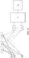
- FIG. 5 An illustrative embodiment of the present invention, as shown in Figure 5 includes:
- the present invention provides that a constellation of antennas (normally at least three, but typically fifteen or even many hundred in line of sight within the area in which the ground based UE resides) provide co-operative or inter-platform beamforming for very targeted communications with individual users, see Figure 1 : the beam (12) used for a single user within a particular patch is very small.
- a targeted beam may be formed on a single UE: the intersection of this with the ground can be presented to the mobile network as an individual cell which has the ability to use the full available resources (signal bandwidth and communication power) for communication to a single piece of UE.
- These cells are termed herein as "dynamic femtocells" or DF-Cells.
- Figure 10 illustrates the ability of this system to track UE within a building.
- a constellation of aerial antennas supported by aircraft are situated above a building (112) in which there are two UEs (1 and 2) (110).
- each aircraft shown represents a number of aircraft. If the building walls and roof are relatively impervious to the radio wavelength being used for communication, communication will depend on radio signals being transmitted and received through windows and other apertures. In this case only antennas in line of sight of UE 1 - within the cone defined by ⁇ 1 or the reflection from the floor from UE 2 within cone defined by ⁇ 2 will contribute significantly to communication. It is therefore important that the choice of antennas used and the weights and phases allocated to the antennas generate beams from the antenna constellation that can reflect the local conditions to the UE to allow beams of an appropriate direction and position.
- Such choices can improve the signal strength at the UE and reduce the expenditure of otherwise wasted energy on the aerial platforms thereby increasing endurance or power available for other communication needs.
- high data rates in excess of 100 Mbps to or from individual UE are possible.
- the communication of particular data, applications and content may have deleterious effects on user equipment or particular users for example children.
- the present system allows a system operator to introduce checks in the processing centre or elsewhere on data, applications and content to protect user equipment or particular users.
- the invention relates to a method of receiving and/or transmitting data, applications and/or content to an antenna on user equipment, the method utilising the network or process as described herein.
- the present system allows for much more precise identification of geographic location within a wide area coverage, along with higher data rates, than current systems.
- location can often be identified within metres and even to sub-metre resolution, dependant on propagation conditions. This allows the system at the resolution of rooms or buildings the capability to restrict access to specific or general user equipment on a continuous or intermittent basis.
- Such an access capability has the potential to allow appropriate authorities within properties over which they have suitable rights to restrict or modify access, for example to control under age or visitor access in specific rooms, at specific times or continuously.
- This capability also has the ability to readily provide information on the location of the user equipment to another party contacting another piece of user equipment.
- the invention relates to a process for the management of access to the apparatus or process described herein, by specifying the location and/or time that will permit or reject the transmission or reception of information to that location.
- the UE may include transmitters or receivers or both.
- the aerial antennas can be phased arrays or conventional antennas or both.
- the present invention involves the use of advanced phased arrays, which enable "intra-array beamforming” or beamforming within a single antenna.
- advanced phased arrays which enable "intra-array beamforming" or beamforming within a single antenna.
- Phased arrays consist of a large number of individual antenna elements, but in the rest of this document "antenna(s)" will refer to one or more phased arrays or one or more conventional individual antenna(s) such as a horn antenna(s).
- Phased arrays have a particular advantage for high altitude aircraft and other platforms in that their aspect ratio, the ratio of their width to depth is generally low, and thereby often easier to mount in a structure where low aerodynamic drag is required.
- Antenna(s) mounted on high altitude platforms can communicate both to and from UE, not primarily connected other than via the high altitude platform antenna(s) with a large ground based communication network such as the internet or a cellular network.
- a large ground based communication network such as the internet or a cellular network.
- Such antenna(s) can also communicate with backhaul ground based stations ("BG stations") which are directly connected to a large ground based communication network and provide "backhaul" known to those skilled in the art.
- BG stations backhaul ground based stations
- the UE may include transmitters or receivers or both.
- the aerial antennas can be phased arrays or conventional antennas or both.
- FIG. 2 is an illustration of a small phased array (21). It has an array of small antenna elements (22), which are connected to either the input of low noise amplifiers prior to digitization as a receiving system or to output amplifiers for transmission. Each antenna element is used independently and by controlling the precise time, or phase, of a signal between elements then a beam can be formed in a similar fashion as with a parabolic dish.
- the phased array may be designed so the antenna elements are all planar as shown in Figure 2 where two or more layers (23) define the electromagnetic performance.
- the phased array can also be a more complex shape for example, "bowed" so that the outermost elements are pointing at an angle to the axis of the array.
- Each antenna element is connected to a low noise amplifier.
- the requirement is to have a linearly increasing signal delay across the width of the array; this can be done in either the analogue or digital domain.
- the diagram at the top of Figure 3 shows the relative delays (32) on the y-axis (30) used in producing the beam (35) where the distance across the antenna is plotted on the x-axis (31).
- the signals from all the antenna elements suitably relatively delayed are then summed to form a composite signal, which is a "beam.”
- the beam size is given approximately by ⁇ /d where ⁇ is the wavelength and d the diameter of the array. In the case of a 2GHz signal and a 1.5-metre diameter array, the beam would normally be ⁇ 5.7° wide.
- antenna element weighting this can be tailored to widen the beam. If required this enables the beams to be varied to give approximately uniform coverage on the ground as changes in the elevation of the array from points on the ground result in the beam being spread to a greater or lesser extent over the surface.
- Phased arrays also have the benefit that, by using recent developments in digital technology, very wide bandwidths can be implemented.
- the frequency range of recent, planar antenna elements can be as high as 3:1 from the lowest to the highest frequency supported.
- multiple conducting or partially conducting layers are each situated in planes parallel to each other and at 90 degrees to the axis of the antenna.
- Forming many beams in the digital domain can be readily achieved, the only requirement after digitization is additional processing resources and data bandwidth to communicate or further process all the beam information.
- the maximum number of "independent" beams that can carry data unique from all other beams cannot exceed the total number of antenna elements in the array. For example, if an array has 300 independent antenna elements (separated by ⁇ /2 or greater) there can be a maximum of 300 independent beams; more beams than this can be formed but these beams will not all be independent. In this instance the non-independent beams will each transmit and receive the same (or similar) encoded information - these beams may still be utilised by appropriate resource sharing schemes or in other ways relevant to the invention.
- Phased arrays can form beams over a scan angle range up to approximately ⁇ 60° from the axis normal to the plane of the array. This is due to the geometrical limitation of the array where the illumination area of the elements is reduced as a cosine of the scan angle; also the sensitivity of the beam of the individual antenna elements is reduced due to their being off the centre of the beam. The result is that the illumination area of a horizontal array is limited by the maximum scan angle to approximately 60km diameter with large single arrays for transmit and receive, this limit may be extended with more complex shaping of the arrays.
- the receiving array may consist of many planar dual polarized receive elements (68) in a regular array (64). Two polarisations are preferred for the inter-antenna beamforming techniques due to the need for precise amplitude and phase information; also to ensure the best signal reception at the arbitrarily positioned UE.
- Each polarization is amplified, filtered and digitized over the receive bandwidth required.
- the antenna element electronics are conveniently mounted immediately behind the receive antenna element for low noise pickup, simpler assembly and to distribute the heat load over a large area.
- the digitized signal for each polarization is transmitted to the signal processing system for beamforming.
- the array is 1.5-metres in diameter with antenna elements spaced at 7.5cm. This results in approximately 315 antenna elements or 630 signal paths. This gives a service area of 60km diameter broken into ⁇ 160 patches (concepts for a modified array that can cover a wider area are discussed later in this document).
- a position detection system (60), an orientation detection system (62) and a control and coefficient processor (61) interface with a signal processing system (63) which, in this preferred implementation, needs a highly accurate clock system (66) which can be interfaced in turn to a Positioning System (67).
- the transmit array (65) is of a very similar design and size as the receive array. It has many dual polarized transmit elements (69). Digitised signals are computed by the signal processing system for each polarization, transmitted to a digital-to-analogue converter, filtered amplified and passed to the output power amplifier for transmission. As with the receive array, the element electronics can be mounted behind the transmit elements to distribute the heat load and minimize stray radiation.
- the present invention utilises beamforming across the multiple aerial antennas to generate narrow cooperative beams to the UE.
- the system operates by the antennas, e.g. phased arrays on every platform in a "constellation" of multiple arrays each forming one of their component signals onto a specific "patch".
- the signal that is sent from all the arrays to a specific patch carries essentially the same information content (differences could include e.g. noise from quantisation and analogue effects), but has a phase delay across the constellation of antennas, thereby forming a very narrow "synthesized beam” from the individual array beams.
- the phase delay, or time delay for wide band signals, for the data signal from each antenna to a UE is compensated accurately for the different distances in phase space from individual antennas to the UE.
- the delay is calculated such that the signal to the UE from every antenna arrives at the same time and is phase coherent at the UE.
- Signal amplitude from each of the aerial platforms is adjusted such that typically all signals are normalised at the UE, but can be adjusted, for instance to reduce side lobes. These adjustments are known as the "beamforming coefficients" for each signal.
- a similar process is applied to the signal to each UE within a patch and combined to form the overall patch beam for every aerial antenna.
- These beam forming instructions can either be calculated on the ground in a processing centre and transmitted as an encoded representation of the patch beam to each aerial antenna or used at the platform to form the patch beams.
- the processing system similarly applies phase or time delays to the patch beam from every aerial antenna in the constellation and then sums them to form a coherent receive beam on a UE.
- This combined signal is used to communicate with the wider cellular network.
- this processing will be carried out at the ground processing centre which receives an encoded representation of the patch beams received at the aerial antenna.
- the synthesized beams are computed to become "user beams" which track specific UEs.
- This is illustrated in Figure 4 , which shows beam formation in the service area, by a constellation of antennas labelled HAP 1 , HAP 2 to HAP m .
- the antenna on HAP 1 is shown producing three beams (40,42, and 44), which are directed at three patches (41, 43, and 45).
- HAP 2 and HAP m are shown producing similar beams.
- the "maximum beam data rate” (MBDR) that can be transferred to or from a single antenna within a beam is given by the number of bits per second per Hertz bandwidth, multiplied by the bandwidth available. The maximum number of bits per second per Hertz is limited by the signal to noise ratio of the signal, as is well known to those skilled in the art.
- the beam sizes can be adjusted to be larger than the minimum beam size for a single antenna, so that area illuminated by each beam may be tailored to the requirements of the operational environment of the system.
- the "resolution areas” will be comparable in size from one antenna to another. If the aerial antennas are far apart, the “resolution areas” from different antennas will be very different in size.
- the limit to the amount of data that can be transferred within one resolution area given by the number antennas in the constellation multiplied by the MBDR if the resolution area sizes from each of the antennas are similar.
- the available bandwidth can be split into multiple blocks of resources e.g. frequency bands, time slots and codes, thereby increasing the number of UEs that can be supported although with a lower data rate available to each UE.
- Other radio resource sharing techniques can be used. There cannot be more data present in the user beams than is available in the antenna beams.
- the constellation of aerial antennas effectively operates just as would a single antenna having a dimension that is from 1 to 30 kilometres, preferably from 5 to 20 kilometres. Thus, very narrow beams can be generated.
- Weightings on the antenna elements can be varied to control ground based patch sizes based on an optimization function reflecting population density or data rate density, taking into account the orientation and attitude of the antenna platform(s). In this manner if the centre of the constellation is over a large city but at the edge of the service area there is a low population density, beams to and from the constellation may involve only a small fraction of the antenna elements of each array thereby saving power.
- Platforms can be implemented as:
- aerostats 90, 91
- tethers either directly to the ground (93) or indirectly (92).
- Some aerostats (91) are connected indirectly, and some directly (90) to the ground.
- the antennas (94) are wholly contained inside the envelope of the aerostats. They may be partially contained or not contained at all.
- UEs (96) is communicated to by beams (95) from the aerial antennas (94) in a co-operative manner. At least two antennas communicate with each UE.
- the system may consist of one or several types of platform described above.
- the platforms are normally all equipped with at least two phased arrays of equivalent size and number of elements, a transmit array and a receive array, to enable the system to have concurrent transmission and reception for any waveform and multiplexing technique that operates at the selected frequency allocation and bandwidth. It is possible to use a single array, but the electronics required is of greater complexity and weight, and may only support time division multiplexing and not the more usual frequency division multiplexing.
- the arrays form beams that divide the service area into a number of patches. The patches are treated as "cells" by the cellular telephone network.
- the UE may be ground based or could be on a manned or unmanned aircraft at lower altitude than the aerial antennas. unmanned aerial vehicles.
- the UE could also be carried on some form of transportation technology including but not limited to trains, motor vehicles and shipping.
- the system of the present invention can provide a "transparent" link between the cellular network and the individual users' devices in a similar fashion as conventional ground based mast based systems. This provides compatibility with the existing cellular network.
- the present invention allows for the possibility of a substantial amount of data communicated between the platforms and the UEs. Thus there has to be at least the same amount of user data communicated through the backhaul system to and from the platform and processing system.
- the following are some options for transmitting the data from and receiving it to the platforms via the following communication links:
- Both polarisations could be used independently on the backhaul link, potentially halving the number of BG stations required.
- Much of the technology used in the present invention is used in the telecommunications industry and develops techniques used in radio astronomy for beamforming and beam shaping.
- the use of one-dimensional phased arrays, the interface specifications, the data encoding techniques, the use of signal processing etc. are all widely used by the existing cellular telecommunication systems.
- the present invention integration results in a very high performance system that interfaces compatibly into most existing cellular telephone network technology.
- the present invention is managed by a processing system, which may be a distributed system or, as shown in the figures, figure 1 shows a processing centre (1), which is normally ground based, saving weight and power on the aerial platforms.
- the processing system interfaces to the cellular telephone network (2), and it provides direct control of the signals being used by the platforms to communicate with the UEs.
- the processing system may be physically distributed between a processing centre, processing co-located with the aerial antennas and/or backhaul ground stations, and processing services provided by third-party (known as "cloud") providers.
- cloud third-party
- the processing system provides the interface to the cellular network through a defined interface to the cellular network.
- the processing system computes for the aerial antennas:
- the processing system can compute and provide
- the BG stations can be linked directly to a processing centre via high-speed connections such as fibre optic data links or direct microwave links.
- the signals at the platform are complex in that they define all the characteristics to enable the constellation of platform phased arrays to beamform precisely onto individual users.
- the processing system may comprise at least one processing centre with some processing required on each platform.
- Such processing centres are ideally located at ground-level, for simplicity.
- ground level processing dominates the overall signal processing capability, consuming over 70 per cent, preferably over 90 per cent of the signal processing electronics electrical power requirements.
- the processing system also determines how the system presents itself to the cellular network, including providing the required interface to enable efficient resource allocation.
- the processing system may be capable of a further range of enabling functions, as will now be illustrated.
- the processing system may be capable of determining when the formation of a DF-Cell is required to permit up to the maximum resource allocation to a given piece of user equipment.
- the processing system will support all resource allocation methods required by the cellular network including, but not limited to, frequency and time multiplexing.
- the processing system will also determine the frequencies that will be used by each platform. This can be up to the full bandwidth of the frequency allocations or restricting the bands for specific network or mobile phone operators using either overlaid systems according to the present invention or a mixture of ground based antennas and the present system. It would also support co-operative use of multiple operators, assuming suitable agreements can be reached.
- the system can also use time division multiplexing or other radio resource sharing techniques.
- the signal processing system uses information transmitted from the processing centre to form required beams on the UEs and (if required) on the BG stations.
- the data in the beams that are formed is retransmitted to users, BG stations or used by the control processors on the aircraft.
- processing on the platforms is preferably minimised, however there may be at least some processing carried out there which can include:
- Accurate time determination at the moving aerial antennas is essential to the precise reception and transmission using beamforming of the signals.
- a suitable clock generation uses a GPS system for long-term (greater than ten's of seconds) accuracy and an oven temperature stabilized crystal oscillator for short-term accuracy. This combination will give the phase precision required for both local aircraft beamforming and beamforming between aircraft. The requirement is to have phase stability for the analogue to digital converters, ADCs, and digital to analogue converters, DACs, to have precise sampling at all times.
- BG stations Backhaul Ground Stations
- the present invention may benefit from the provision of one or more BG stations.
- the BG stations can provide the communication links to and from the platforms and the processing centre.
- Each BG station should be able to communicate independently with as many platforms in line of sight as possible, to maximize the data rate capabilities of the platforms.
- phased arrays as the communication system at the BG stations will provide this facility.
- the design of these phased arrays can be similar to those on the platforms.
- BG stations can provide the high-speed data links between the aircraft and the processing centre.
- the BG stations can have multi-beaming capability so that they can each communicate with each aerial antenna independently when there is a constellation of multiple antennas, to provide the high data rates required for the network.
- the data rate to or from each BG station can be increased by a factor equal to the number of aircraft being communicated with over that which would be possible with a single aircraft.
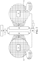
- phased arrays An implementation using phased arrays similar to the systems used on the aircraft is illustrated in Figure 7 . As with the aircraft phased arrays there are separate transmit (75) and receive (74) arrays.
- the receive array (74) has a large number of elements (78) which provide signals to the receiver processing system (72).
- the transmit array (75) has a large number of elements (79) which receive signals from the transmitter processing system (73).
- Both receiver and transmitter processing systems interface (71) with the processing system (70). They also can require input from a clock system (76), which in turn receives input from a positioning system (77).
- BG stations are separated far enough apart for beams from the individual aircraft arrays to resolve them independently with different array beams. This is to provide a sufficient aggregate data rate to every aircraft.
- BG stations are under the direct control of the processing system; the processing system determines the amplitude and phase for every array element.
- BG stations In certain locations where the availability of BG stations is low, it may be advantageous to link one aircraft with another more suitably located over BG stations by laser or free space optical devices.
- These have been developed in recent years and allow high data rate communication (greater than 1 Giga bit per second) with modest (under 100W) power consumption and can be of modest weight of less than 25 kg but able to communicate in the stratosphere at distances of at least 60 km, and more preferably of 250 km and on occasion of 500 km or more.
- one or more aerial antennas it is possible for one or more aerial antennas to be linked to BG stations many hundreds if not thousands of kilometres distant by utilizing laser links between additional aircraft.
- the aircraft are fitted with large phased arrays and associated signal processing and control systems, as illustrated in Figure 6 .
- phased arrays there are two phased arrays: one for receive (64) and the other for transmit (65). This is to ensure that there is full separation between the two paths such that both systems can operate using frequency division duplex, FDD, systems; these are the most popular cellular phone communication links.
- FDD frequency division duplex
- Two arrays can also support the alternative time division duplex, TDD, systems without the complexity of sharing an array for both transmit and receive.
- these arrays both have many individual receive or transmit elements (68, 69); the array signals are combined in the signal processing system (63) to produce the required beams.
- the system can keep track of UEs in a similar fashion to a conventional ground based network.
- the UE needs to be kept within the cooperative beam when a call or data transfer is in progress.
- the beam on the UE could be very focused, e.g. of approximately 1 metre diameter. There are then two further functions required:
- Narrow bandwidth secondary beam(s) can be used to rapidly sample in a pattern around the user's position, increased signal strength in a particular direction or area can then be used to modify antenna weightings and beam position and direction.
- the first cooperative beam is generated at a first point in time, and at a second point in time, carrying out a second beamforming operation to ensure that the cooperative beam is directed to the position of the moving user antenna.
- Figure 11 illustrates an example of how beams from one or more aerial antenna(s) can be modified to give good coverage up to a national boundary but minimize energy spillover into an adjacent country.
- patches of coverage beams from individual antennas or multiple antennas follow a regular grid arrangement where the position of the grid elements is given on the x -axis (133), in this case East - West, by numerals and on the y axis (132), in this case North - South, by letters.
- the element 136 can be referred to as having location G7.
- An irregular national border is shown (135).
- Shaded squares illustrate where energy is being transmitted to by the aerial antenna system. It can be seen that to ensure low spillover of energy there is an area next to the border where little energy is transmitted, for example in patches A6,B7,C7,D5,E5, F8 and so forth.
- diagram 131 in Figure 11 shows the same area, with the same y axis (132) and a comparable x- axis (134) but with modification of the antenna element and antenna phasing - and if need be amplitude, to move the patches to the left or right to more closely follow the national border.
- cell G7 (136) has moved, along with its row (G1 to G5) in an easterly direction so it has become located at a new position (137).
- the uncovered area closer to the national border has been significantly reduced.
- the synthesized beams formed using Inter-Antenna beamforming can be similarly controlled, trading sensitivity for beam-shape to minimize artefacts and actively control beamsize.
- the data rate available depends upon the bandwidth available from the band that is in use. For this example, it is assumed that the band is LTE Band 1 (other frequencies are also available): • Uplink: 1920MHz to 1980MHz 60MHz bandwidth • Downlink: 2110MHz to 2170MHz 60MHz bandwidth
- the links to individual UEs will only use the bandwidth required for the function being used, hence the bandwidth can be sub-divided to service as many users as possible.
- the data rates through an example HAP-CELL system are shown in Table 1, as can be seen this is using Band 1 frequencies and 50 aircraft in a fleet.
- the data rates per link are dependent upon the signal to noise ratio of the link; hence there is an expectation of higher data rates in the same bandwidths for the backhaul links than to the UEs. This is because the connection to the backhaul can be much better managed due to the fixed, outdoor nature of the equipment and the potential for using higher transmission power and larger antennas than for mobile UE.
- the maximum data rate to the UE is very high, assuming the use of clear, high SNR connections. As with all cellular networks, the data rate will be adjusted for the actual link performance.
- Table 1 Example HAP-CELL system, 50 aircraft, 1.5m 2GHz single arrays (values used for indicative sizing of the system) System Value Comments No. of Aircraft 10 to 50 Aircraft in a single fleet No. of BG stations 157 - 416 This depends upon encoding and number of polarisations on backhaul links.
- Bandwidth 60MHz LTE Band 1 Chosen band for illustration purposes Wavelength, ⁇ 15 cm ⁇ 2GHz Aircraft height 20km Lower stratosphere and well above commercial airspace Service area diameter 60km Within max.
- Patch size 4.7km x 4.7km Defined by the size of the arrays
- Backhaul data links Implementation Phased array beams Uses additional virtual patches on the aircraft phased arrays Polarisations 2 Dual polarization, for beamforming performance. In principle could use separate polarisations for data - but not considered here.
- User data links Patches 160 For a 60km dia.
- the payload power usage on the aircraft considered is for the communications arrays, the digital processing systems on board and the control and positioning systems. Keeping the aircraft payload power requirements low is important for the limited power availability in either the solar powered aircraft or hydrogen-powered aircraft operating at high altitude.
- the power will scale as the number of antenna elements. Performing as much processing as is practical in the ground based processing facility minimizes the processing requirements at the aircraft. The power for the large number of digital interfaces will dominate the processing power.
- Table 2 This is an example calculated for an aircraft incorporating two 1.5m diameter phased arrays for transmit and receive. Each array has 315 dual polarization antenna elements; each array therefore has 630 signal channels. The power requirements are for ⁇ 1.6kW with these arrays.
- the elements of the processing system located on the platform are implemented using standard components and as such will benefit over time from the improvements in processing available per unit of power consumed.
- Table 2 Estimated power requirements for airplane with 2 x 1.5m 2GHz arrays Subsystem Power each (W) Number Power total (W) Comments Receive array: LNA & gain chain 0.5 630 315 Digitisation & communications 0.2 630 130 Power losses 45 10% power distribution losses Transmit array: DAC & communication 0.2 630 130 Power amplifier 0.5 630 315 Assuming 250mW RF power per polarization Tx, 50% efficiency Power losses 45 10% power distribution Signal processing: Processing 200 10 FPGA's at 20 watts (processing) each Signal transport 0.1 630 65 Inter-FPGA links Control, clocks, orientation: Estimate 400 Substantial processing resources Total 1635
- the aircraft are up to 35 km away and have a round trip link of more than 70km; the processing will have some buffering delays.
- the delays will not add up to more than a few milliseconds which is well within current mobile network specifications of ⁇ 30ms or proposed 5 G specifications of ⁇ 5 ms.
- the HAP-CELL system is intended for use over large areas. For densely populated areas e.g. major cities, there may need to be multiple fleets of aircraft serving multiple service areas. The system readily scales in this fashion and economies of infrastructure and additional communication capabilities become available.
- a multiple system is illustrated in Figure 8 .
- the cellular network and Internet (81) interfaces with one or more processing centres (82), which are linked by fibre optic cables or by microwave (83) to BG stations (84 or 841). Each service area (810, 811,812) is approximately 60km in diameter.
- the service areas can overlap which provides higher total data rate for users.
- There is also the benefit of improved coverage for example, if a user is shielded from a fleet of aircraft by being on the "other side" of a building, then there is likely to be coverage from an adjacent fleet.
- BG stations (841) can service more than one fleet of aircraft if they are suitably positioned.
- the BG stations form beams to each aircraft within a fleet, consequently, provided the fleets are within range then a BG station can service all the fleets within 30km to 35 km.
- the design of an area's coverage should consider how a number of aircraft, e.g. 50-100, should be deployed in fleets to have maximum benefit there may be more, smaller fleets or fewer large ones with appropriate degrees of service area overlap. The details will depend upon the population density and other factors, but the HAP-CELL system can allow these trade-offs to be made.
- the present invention confers the following benefits over existing mobile phone and communication systems:
- High data rate links The traditional operation of a mobile network divides the network into a set of "cells.” Multiple UEs within a cell must share the available resources (signal bandwidth and communication power), which determine the maximum data rate to a user either by radio resource sharing techniques, for example, but not exclusively, sharing bandwidth or time multiplexing.
- a key element is that inter-antenna beamforming is used to create a DF-Cell centred on a specific device. This permits all the resources, which can be made available by the implemented protocol to be used by a single device. Resource sharing, as in standard implementations, is also supported by the invention.
- Focused RF power at the user Due to Inter-Antenna beamforming the power at the precise user location is increased. This minimizes the power usage on the platform and improves link quality. This is described in detail in Tables 2 and 3.
- Scalable capability The number of users and data rate can be increased easily and quickly - without normally the need for additional ground based infrastructure - by adding more platforms in the same area. The addition of extra BG stations can normally be avoided unless very large capacity increases over the previous infrastructure is needed. This feature, in itself, provides substantial resilience in the system. For example, losing one platform out of ten similar platforms, due to an equipment fault or maintenance or temporarily being unavailable due to flight patterns, would reduce the capacity of the system by 10%, but still give complete coverage within the service area. Similarly, losing one ground station out of a hundred would also only lose 1% of the communication data rate capability. This is significantly better than the loss of a standard mobile phone cell mast where all users within the cells it controls will lose the signal.
- Coverage area can be accurately tailored: Phased array and beamforming technology enables the coverage area to be more accurately controlled than with ground-based systems. This is important for operation close to country borders.
- the beamforming technology needs to manage the effects of reflections such as from walls; or diffraction effects such as from the edges of intervening objects, such as the roofs of buildings, if the UE is ground based.
- the antennas on many of the platforms are in line-of-sight or close to it from the UE.
- Table 3 Glossary of terms used in this document ADC Analogue to digital converter.
- Within the HAP-CELL systems converts the analogue RF signal to digital data stream for signal processing.
- Algorithm A process or code by which the power levels at a particular UE can be set. This might be to optimise the powers to antenna elements to ensure a minimum power level for all UE's or to ensure that given UE's had a higher power level.
- Antenna A phased array or conventional antenna.
- Antenna element An individual transmitting or receiving antenna within a phased array.
- Each has an individual electronic system for linking to a signal processing system
- Antenna weightings or coefficients Typically, complex numbers that are used within the signal processing chain to adjust the amplitude and phase of the signals to and from individual antenna elements to form the desired beams from an antenna or constellation of antennas.
- Backhaul communications The data communication links from the aerial platforms to the ground and ultimately to the HAP-CELL processing centre.
- Beam Directional signal transmission or reception from an antenna Beamforming Beamforming is a signal processing technique used for multiple antennas or in the case of phased arrays, antenna elements, to give directional signal transmission or reception.
- Beamwidth The angular beamwidth, as understood by practitioners skilled in the art, depends upon the ratio of the wavelength of the radiation used in said communications system divided by the separation between pairs of aerial antennas; for the conditions envisaged for this invention may be designed to be a wavelength of 15 centimetres and an aerial antenna separation of approximately 10 kilometres results in a beamwidth of less than 50 micro radians and beam size on the ground of less than 2 metres
- Beamforming coefficients Typically, these are complex numbers that are used within the signal processing chain to adjust the amplitude and phase of the signals to and from individual antenna elements to form the desired beams from an array or constellation of arrays.
- BG stations Backhaul ground stations.
- the ground based radio links to each of the platforms.
- Cell The logical functionality provided within an area on the earth's surface supplied with radio service. Each of these cells is assigned with multiple frequencies.
- Constellation A number of antennas supported by HAPs operating cooperatively over the same service area to provide communications to many UEs.
- Cooperative beam A highly directional signal transmission or reception formed by coherently aligning beams from multiple antennas mounted on aerial platforms.
- Correlating Correlating is a mechanism to cross-multiply the signals to or from pairs of antenna elements, this is a fundamental part of interferometry to form the Fourier transform of the incoming or outgoing signals.
- DAC Digital to analogue converter.
- DBF Digital beam-forming Femtocell The area, normally on the ground, which is intersected by a beam carrying information to and from a piece of UE and at least three aerial antennas involved in inter-antenna cooperative beam forming.
- Dynamic femtocell DF Cell
- HAP High Altitude Platform This is the vehicle that carries the communications equipment. It can e.g. be an unmanned aircraft, tethered balloon or untethered balloon.
- HAP-CELL High altitude platform cellular system which refers to an example of an implementation using HAPs to provide cellular communications.
- HAP-CELL Processing centre A facility associated with one or more HAP-CELL systems to control the communications to and from BG Stations, HAPs, UEs and the cellular network.
- Macrocells A cell in a mobile phone network that provides radio coverage served by a high power cellular base station.
- Microcell A microcell is a cell in a mobile phone network served by a low power cellular base station, covering a limited area such as a mall, a hotel, or a transportation hub.
- a microcell uses power control to limit the radius of its coverage area.
- Patch The patch is a specific area, normally on the ground, which can be illuminated by every antenna in the constellation with an independent beam.
- Payload The equipment carried on a Platform.
- Phased Array A type of antenna consisting of many small antenna elements, which are controlled electronically to form one or more Phased Array Beams. Phased arrays can be used on the HAPs or BG stations Phased Array Beam The electromagnetic beam formed by a phased array. Phased array beams from a HAP illuminates a patch.
- Platform The platform that carries the payload - an aircraft., tethered aerostat or free flying aerostat.
- Service Area The area of ground over which communications coverage is provided by one or more HAP-CELL aircraft.
- a service area is split into many patches.
- Spread Spectrum Technologies A technique in which a telecommunication signal is transmitted on a bandwidth considerably larger than the frequency content of the original information.
- Synthesised Beam The beam formed by beamforming HAPs in a constellation. The beam is small and illuminates a "dynamic femtocell.” Transmitting data Data can be transmitted over an RF link such as the aerial antennas. Can also refer to communicating data within a system over local links such as fibres or wires.
- UE See User Equipment.
- User Equipment The equipment used by an individual user, typically a mobile phone, tablet, or computer, but also more generally equipment with or connected to an antenna which may be stationary or in a moving situation such as in a vehicle, vessel or aircraft. Abbreviated to UE.
- User Beam A synthesised beam that tracks specific user equipment Weightings See Antenna weightings
Landscapes
- Engineering & Computer Science (AREA)
- Remote Sensing (AREA)
- Radar, Positioning & Navigation (AREA)
- Computer Networks & Wireless Communication (AREA)
- Physics & Mathematics (AREA)
- Signal Processing (AREA)
- General Physics & Mathematics (AREA)
- Aviation & Aerospace Engineering (AREA)
- Astronomy & Astrophysics (AREA)
- Electromagnetism (AREA)
- Power Engineering (AREA)
- Mobile Radio Communication Systems (AREA)
- Variable-Direction Aerials And Aerial Arrays (AREA)
Claims (12)
- Procédé de formation de faisceau inter-antenne aérienne coopérative pour une communication entre (a) de multiples plates-formes mobiles (9, 90, 91), chaque plate-forme ayant une antenne aérienne (15, 16, 94) y étant montée, de sorte qu'une ou plusieurs des antennes aériennes (15, 16, 94) ont des positions et des orientations variables dans le temps, et (b) au moins une antenne montée sur un équipement utilisateur (11, 96) ayant une altitude inférieure à celle des antennes aériennes (15, 16, 94) ; le procédé impliquant la transmission de données relatives aux positions et orientations des antennes aériennes à un système de traitement, le système de traitement (1, 53) déterminant des instructions de formation de faisceau pour les antennes aériennes sur la base des données relatives aux positions et orientations des antennes aériennes ;
le système calculant et transmettant les instructions de formation de faisceau aux antennes aériennes (15, 16, 94), les antennes aériennes transmettant ou recevant ainsi des signaux composants respectifs (6, 7, 95) associés à chaque antenne d'utilisateur, les signaux composants (6, 7, 95) associés à chaque antenne d'utilisateur ayant essentiellement le même contenu d'informations mais différant dans leur phase, de manière à former un faisceau coopératif (12) à partir de la somme coopérative des signaux entre les antennes aériennes (15, 16, 94) et l'antenne d'utilisateur,
où la position respective de chaque antenne aérienne est déterminée en utilisant un procédé impliquant deux étapes,
la première étape comprenant de déterminer, par GNSS différentiel, une première position de l'antenne dans les limites de précision réalisables ;
la seconde étape comprenant de détecter les signaux provenant de chacune des multiples stations au sol en corrélant certains ou tous les éléments d'antenne sur l'antenne aérienne, en trouvant la phase du signal provenant de chaque station au sol en essayant de nombreux retards relatifs différents des signaux reçus à chaque station au sol et en trouvant le retard qui maximise les signaux reçus de chaque station au sol et en accordant ainsi une portée de chaque station au sol individuelle à l'antenne aérienne pour donner une distance plus précise dans le volume défini par la première étape ;
la seconde étape comprenant en outre de rechercher la position de l'antenne à partir de l'intersection des distances séparant chaque station terrestre individuelle de l'antenne aérienne. - Réseau de communication, le réseau comprenant de multiples plates-formes mobiles (9, 90, 91), chaque plate-forme ayant une antenne aérienne (15, 16, 94) y étant montée, de sorte qu'une ou plusieurs antennes aériennes (15, 16, 94) ont des positions et des orientations variables dans le temps, et sont agencées pour communiquer avec au moins une antenne d'utilisateur montée sur un équipement d'utilisateur (11, 96) ayant une altitude inférieure à celle des antennes aériennes (15, 16, 94) ; le réseau impliquant un système de traitement (1, 53) adapté pour recevoir des données relatives aux positions et orientations des antennes aériennes (15, 16, 94), le système de traitement étant en outre adapté pour déterminer des instructions de formation de faisceau pour les antennes aériennes sur la base des données relatives aux positions et orientations des antennes aériennes et transmettre les instructions de formation de faisceau aux antennes aériennes, les antennes aériennes étant adaptées pour générer ou recevoir des signaux de composants respectifs (6, 7, 95) associés à chaque antenne d'utilisateur, les signaux de composants (6, 7, 95) associés à chaque antenne d'utilisateur ayant essentiellement le même contenu d'informations mais différant dans leur phase, de manière à former un faisceau coopératif (12) entre la somme coopérative des signaux entre les antennes aériennes (15, 16, 94) et l'antenne d'utilisateur,
et où la position de chaque antenne aérienne est déterminée en utilisant un procédé impliquant deux étapes,
la première étape comprenant de déterminer, par GNSS différentiel, une première position de l'antenne dans les limites de précision réalisables ;
la seconde étape comprenant de détecter les signaux provenant de chacune des multiples stations au sol en corrélant certains ou tous les éléments d'antenne sur l'antenne aérienne, en trouvant la phase du signal provenant de chaque station au sol en essayant de nombreux retards relatifs différents des signaux reçus à chaque station au sol et en trouvant le retard qui maximise les signaux reçus de chaque station au sol et en accordant ainsi une portée de chaque station au sol individuelle à l'antenne aérienne pour donner une distance plus précise dans le volume défini par la première étape ;
la seconde étape comprenant en outre de rechercher la position de l'antenne à partir de l'intersection des distances séparant chaque station terrestre individuelle de l'antenne aérienne. - Procédé selon la revendication 1 ou réseau de communication selon la revendication 2, dans lequel il y a au moins trois antennes aériennes (15, 16, 94), de préférence au moins dix, plus préférablement au moins trente, le plus préférablement au moins cent.
- Procédé selon l'une quelconque des revendications 1 et 3 ou réseau de communication selon l'une quelconque des revendications 2 et 3, dans lequel les données de position et d'orientation sont transmises par les antennes aériennes à au moins une station au sol (51, 52).
- Procédé selon l'une quelconque des revendications 1 et 3 à 4 ou réseau de communication selon l'une quelconque des revendications 2 à 4, dans lequel le système de traitement (1, 53) comprend un centre de traitement au sol.
- Procédé selon l'une quelconque des revendications 1 et 3 à 5 ou réseau de communication selon l'une quelconque des revendications 2 à 5, dans lequel les antennes aériennes forment un faisceau coopératif qui pourrait être fourni par une antenne théorique unique suffisamment grande pour englober les positions des multiples antennes aériennes, où l'antenne théorique a une dimension qui s'étend de 1 à 30 kilomètres, de préférence de 5 à 20 kilomètres.
- Procédé selon l'une quelconque des revendications 1 et 3 à 6 ou réseau de communication selon l'une quelconque des revendications 2 à 6, dans lequel au moins une antenne aérienne se trouve à un emplacement élevé d'au moins 10 000 m, de préférence d'au moins 17 000 m, plus préférablement dans la stratosphère.
- Procédé selon l'une quelconque des revendications 1 et 3 à 7 ou réseau de communication selon l'une quelconque des revendications 2 à 7, dans lequel au moins une des antennes aériennes (15, 16, 94) est une antenne réseau à commande de phase (74, 75).
- Procédé selon l'une quelconque des revendications 1 et 3 à 8 ou réseau de communication selon l'une quelconque des revendications 2 à 8, dans lequel les plates-formes comprennent des aéronefs solaires sans pilote, des dirigeables ou des véhicules aériens hybrides.
- Procédé selon l'une quelconque des revendications 1 et 3 à 9 ou réseau de communication selon l'une quelconque des revendications 2 à 9, dans lequel les plates-formes comprennent des aéronefs à hydrogène sans pilote.
- Procédé selon l'une quelconque des revendications 1 et 3 à 10 ou réseau de communication selon l'une quelconque des revendications 2 à 10, dans lequel la formation de faisceau est adaptée dynamiquement au moyen de la modification des pondérations des antennes aériennes pour fournir des conditions de service optimales.
- Procédé selon l'une quelconque des revendications 1 et 3 à 11 ou réseau de communication selon l'une quelconque des revendications 2 à 11, dans lequel au moins une partie de l'équipement utilisateur est basée au sol.
Applications Claiming Priority (2)
| Application Number | Priority Date | Filing Date | Title |
|---|---|---|---|
| GB1503613.0A GB2536015A (en) | 2015-03-03 | 2015-03-03 | Process and apparatus for communicating with a user antenna |
| PCT/GB2016/050540 WO2016139466A1 (fr) | 2015-03-03 | 2016-03-02 | Procédé et appareil pour communiquer avec une antenne utilisateur |
Publications (2)
| Publication Number | Publication Date |
|---|---|
| EP3266116A1 EP3266116A1 (fr) | 2018-01-10 |
| EP3266116B1 true EP3266116B1 (fr) | 2021-05-12 |
Family
ID=52876457
Family Applications (1)
| Application Number | Title | Priority Date | Filing Date |
|---|---|---|---|
| EP16709504.1A Active EP3266116B1 (fr) | 2015-03-03 | 2016-03-02 | Procédé et appareil pour communiquer avec une antenne utilisateur |
Country Status (7)
| Country | Link |
|---|---|
| US (1) | US10530429B2 (fr) |
| EP (1) | EP3266116B1 (fr) |
| CN (1) | CN107431508B (fr) |
| BR (1) | BR112017018563A2 (fr) |
| GB (1) | GB2536015A (fr) |
| IL (1) | IL253880B (fr) |
| WO (1) | WO2016139466A1 (fr) |
Cited By (1)
| Publication number | Priority date | Publication date | Assignee | Title |
|---|---|---|---|---|
| US20220268871A1 (en) * | 2021-02-24 | 2022-08-25 | Bluehalo, Llc | System and method for a digitally beamformed phased array feed |
Families Citing this family (21)
| Publication number | Priority date | Publication date | Assignee | Title |
|---|---|---|---|---|
| KR101881166B1 (ko) * | 2016-05-17 | 2018-07-23 | 한국전자통신연구원 | 이동무선백홀 네트워크의 빔 포밍 통신 장치 및 방법 |
| JP6615827B2 (ja) * | 2017-05-12 | 2019-12-04 | ソフトバンク株式会社 | 通信システム及び遠隔制御装置 |
| US11754671B2 (en) * | 2018-05-07 | 2023-09-12 | Mitsubishi Electric Corporation | Incoming wave count estimation apparatus and incoming wave count incoming direction estimation apparatus |
| FR3081620B1 (fr) * | 2018-05-25 | 2020-07-17 | Greenerwave | Procede de determination d'une caracteristique d'un recepteur dans un milieu, et systeme mettant en oeuvre ce procede |
| CN108769928B (zh) * | 2018-06-08 | 2020-09-25 | 清华大学 | 基于船舶位置的海域通信波束协同控制方法和系统 |
| US11122574B2 (en) * | 2018-08-08 | 2021-09-14 | Qualcomm Incorporated | Indication of antenna coherence for phase difference of arrival and angle of departure estimation |
| GB2580296A (en) | 2018-11-09 | 2020-07-22 | Stratospheric Platforms Ltd | Communication network and method of making a connection |
| GB2580294A (en) | 2018-11-09 | 2020-07-22 | Stratospheric Platforms Ltd | Communication network and method of wireless communication |
| GB2580295A (en) * | 2018-11-09 | 2020-07-22 | Stratospheric Platforms Ltd | Communication network and method of maintaining connection |
| CN109743093B (zh) * | 2018-12-26 | 2020-12-04 | 北京邮电大学 | 一种无人机毫米波通信波束追踪方法 |
| GB201901060D0 (en) | 2019-01-25 | 2019-03-13 | Univ York | Service cell selection |
| CN109918724B (zh) * | 2019-01-30 | 2023-03-17 | 上海卫星工程研究所 | 星载遥感仪器光路组件位移变形对视向量影响的分析方法 |
| US12231219B2 (en) | 2019-09-24 | 2025-02-18 | Samsung Electronics Co., Ltd. | Methods and systems for sharing aerial assets amongst terrestrial network operators |
| CN111257911B (zh) * | 2020-03-05 | 2022-08-12 | 西安空间无线电技术研究所 | 一种基于数字波束成形的码片级脉冲跳时导航信号生成与播发实现方法 |
| US11024957B1 (en) * | 2020-04-02 | 2021-06-01 | Loon Llc | Triggered generation of nulling signals to null an RF beam using a detachable nulling subassembly |
| US11888569B2 (en) * | 2020-11-13 | 2024-01-30 | Intelsat US LLC | Communication system for multiple-input-multiple-output (MIMO) communication with aerial platform |
| CN112505707B (zh) * | 2021-01-29 | 2021-06-01 | 成都远望探测技术有限公司 | 一种x波段双极化快速扫描相控阵天气雷达 |
| JP7318047B1 (ja) | 2022-03-24 | 2023-07-31 | ソフトバンク株式会社 | 通信中継装置、遠隔制御装置、システム、エリア制御方法及びプログラム |
| CN114844581B (zh) * | 2022-05-31 | 2023-06-06 | 中国联合网络通信集团有限公司 | 确定haps多面板相控阵天线覆盖效果的方法及装置 |
| CN115859681B (zh) * | 2022-12-27 | 2026-03-13 | 中国人民解放军火箭军工程大学 | 无纺布/蜂窝吸波结构等效电磁参数计算模型的构建方法 |
| US20240302526A1 (en) * | 2023-03-09 | 2024-09-12 | Atmospheric & Space Technology Research Associates, L.L.C dba Orion Space Solutions | Remote sensing instrument technologies for heliophysics reflective total electron content (reflectec) |
Citations (3)
| Publication number | Priority date | Publication date | Assignee | Title |
|---|---|---|---|---|
| WO2000014902A2 (fr) * | 1998-09-08 | 2000-03-16 | Angel Technologies Corporation | Reseau permettant d'assurer des communications sans fil au moyen d'une plate-forme atmospherique |
| US6473033B1 (en) * | 2001-03-18 | 2002-10-29 | Trimble Navigation, Ltd | Integrated pseudolite/satellite base station transmitter |
| US20110285586A1 (en) * | 2010-05-18 | 2011-11-24 | Kendall Ferguson | Global navigation satellite system (gnss) reference station integrity monitoring and assurance |
Family Cites Families (16)
| Publication number | Priority date | Publication date | Assignee | Title |
|---|---|---|---|---|
| US5359332A (en) * | 1992-12-31 | 1994-10-25 | Trimble Navigation Limited | Determination of phase ambiguities in satellite ranges |
| US5477458A (en) * | 1994-01-03 | 1995-12-19 | Trimble Navigation Limited | Network for carrier phase differential GPS corrections |
| US5518205A (en) | 1994-09-06 | 1996-05-21 | Rockwell International Corporation | High altitude, long duration surveillance system |
| US5754139A (en) * | 1996-10-30 | 1998-05-19 | Motorola, Inc. | Method and intelligent digital beam forming system responsive to traffic demand |
| AU2001230871A1 (en) * | 2000-01-10 | 2001-07-24 | The Johns-Hopkins University | Optical communication system using a high altitude tethered balloon |
| US7281681B2 (en) | 2000-04-03 | 2007-10-16 | Aerovironment Inc. | Hydrogen powered aircraft |
| EP1277253A2 (fr) * | 2000-04-14 | 2003-01-22 | Aerovironment Inc. | Systeme de communication a antenne active |
| US6941107B2 (en) * | 2001-01-19 | 2005-09-06 | The Directv Group, Inc. | Stratospheric platform based surface vehicle tracking and mobile data network |
| US6618010B2 (en) * | 2001-11-14 | 2003-09-09 | United States Of America As Represented By The Administrator Of The National Aeronautics And Space Administration | Passive tracking system and method |
| US8280309B2 (en) * | 2005-04-08 | 2012-10-02 | The Boeing Company | Soft handoff method and apparatus for mobile vehicles using directional antennas |
| FR2922051A1 (fr) * | 2007-10-04 | 2009-04-10 | Axess Europ S A | Systeme d'antenne embarque de poursuite de satellite avec controle de polarisation |
| US9295006B2 (en) * | 2011-02-09 | 2016-03-22 | Qualcomm Incorporated | Real-time calibration of an air to ground communication system |
| US9100085B2 (en) * | 2011-09-21 | 2015-08-04 | Spatial Digital Systems, Inc. | High speed multi-mode fiber transmissions via orthogonal wavefronts |
| DE102011116841B4 (de) | 2011-10-25 | 2017-10-26 | Airbus Defence and Space GmbH | Höhenluftfahrzeug, Luftfahrzeugverband und Verfahren zum Betreiben eines Luftfahrzeugverbands |
| US20140168010A1 (en) * | 2011-12-22 | 2014-06-19 | Farrokh Mohamadi | Extended range, high data rate, point-to-point crosslink placed on fixed or mobile elevated platforms |
| US8953478B2 (en) * | 2012-01-27 | 2015-02-10 | Intel Corporation | Evolved node B and method for coherent coordinated multipoint transmission with per CSI-RS feedback |
-
2015
- 2015-03-03 GB GB1503613.0A patent/GB2536015A/en not_active Withdrawn
-
2016
- 2016-03-02 BR BR112017018563A patent/BR112017018563A2/pt not_active Application Discontinuation
- 2016-03-02 US US15/554,663 patent/US10530429B2/en active Active
- 2016-03-02 EP EP16709504.1A patent/EP3266116B1/fr active Active
- 2016-03-02 CN CN201680013306.8A patent/CN107431508B/zh not_active Expired - Fee Related
- 2016-03-02 WO PCT/GB2016/050540 patent/WO2016139466A1/fr not_active Ceased
-
2017
- 2017-08-07 IL IL253880A patent/IL253880B/en active IP Right Grant
Patent Citations (3)
| Publication number | Priority date | Publication date | Assignee | Title |
|---|---|---|---|---|
| WO2000014902A2 (fr) * | 1998-09-08 | 2000-03-16 | Angel Technologies Corporation | Reseau permettant d'assurer des communications sans fil au moyen d'une plate-forme atmospherique |
| US6473033B1 (en) * | 2001-03-18 | 2002-10-29 | Trimble Navigation, Ltd | Integrated pseudolite/satellite base station transmitter |
| US20110285586A1 (en) * | 2010-05-18 | 2011-11-24 | Kendall Ferguson | Global navigation satellite system (gnss) reference station integrity monitoring and assurance |
Cited By (37)
| Publication number | Priority date | Publication date | Assignee | Title |
|---|---|---|---|---|
| US20220268871A1 (en) * | 2021-02-24 | 2022-08-25 | Bluehalo, Llc | System and method for a digitally beamformed phased array feed |
| US20220271439A1 (en) * | 2021-02-24 | 2022-08-25 | Bluehalo, Llc | System and method for a digitally beamformed phased array feed |
| US11664594B2 (en) | 2021-02-24 | 2023-05-30 | Bluehalo, Llc | System and method for a digitally beamformed phased array feed |
| US11670855B2 (en) | 2021-02-24 | 2023-06-06 | Bluehalo, Llc | System and method for a digitally beamformed phased array feed |
| US11695209B2 (en) | 2021-02-24 | 2023-07-04 | Bluehalo, Llc | System and method for a digitally beamformed phased array feed |
| US11742579B2 (en) | 2021-02-24 | 2023-08-29 | Bluehalo, Llc | System and method for a digitally beamformed phased array feed |
| US11742578B2 (en) | 2021-02-24 | 2023-08-29 | Bluehalo, Llc | System and method for a digitally beamformed phased array feed |
| US11777215B2 (en) | 2021-02-24 | 2023-10-03 | Bluehalo, Llc | System and method for a digitally beamformed phased array feed |
| US11791557B2 (en) * | 2021-02-24 | 2023-10-17 | Bluehalo, Llc | System and method for a digitally beamformed phased array feed |
| US20230352836A1 (en) * | 2021-02-24 | 2023-11-02 | Bluehalo, Llc | System and method for a digitally beamformed phased array feed |
| US11817636B2 (en) * | 2021-02-24 | 2023-11-14 | Bluehalo, Llc | System and method for a digitally beamformed phased array feed |
| US11824279B2 (en) * | 2021-02-24 | 2023-11-21 | Bluehalo, Llc | System and method for a digitally beamformed phased array feed |
| US11824280B2 (en) | 2021-02-24 | 2023-11-21 | Bluehalo, Llc | System and method for a digitally beamformed phased array feed |
| US11843188B2 (en) | 2021-02-24 | 2023-12-12 | Bluehalo, Llc | System and method for a digitally beamformed phased array feed |
| US11870159B2 (en) | 2021-02-24 | 2024-01-09 | Bluehalo, Llc | System and method for a digitally beamformed phased array feed |
| US11955727B2 (en) | 2021-02-24 | 2024-04-09 | Bluehalo, Llc | System and method for a digitally beamformed phased array feed |
| US11996634B2 (en) | 2021-02-24 | 2024-05-28 | Bluehalo, Llc | System and method for a digitally beamformed phased array feed |
| US12009606B2 (en) | 2021-02-24 | 2024-06-11 | Bluehalo, Llc | System and method for a digitally beamformed phased array feed |
| US12021317B2 (en) | 2021-02-24 | 2024-06-25 | Bluehalo, Llc | System and method for a digitally beamformed phased array feed |
| US12034228B2 (en) | 2021-02-24 | 2024-07-09 | Bluehalo, Llc | System and method for a digitally beamformed phased array feed |
| US12062862B2 (en) | 2021-02-24 | 2024-08-13 | Bluehalo, Llc | System and method for a digitally beamformed phased array feed |
| US12062861B2 (en) | 2021-02-24 | 2024-08-13 | Bluehalo, Llc | System and method for a digitally beamformed phased array feed |
| US12080958B2 (en) | 2021-02-24 | 2024-09-03 | Bluehalo, Llc | System and method for a digitally beamformed phased array feed |
| US12088021B2 (en) | 2021-02-24 | 2024-09-10 | Bluehalo, Llc | System and method for a digitally beamformed phased array feed |
| US12113302B2 (en) | 2021-02-24 | 2024-10-08 | Bluehalo, Llc | System and method for a digitally beamformed phased array feed |
| US12119563B2 (en) | 2021-02-24 | 2024-10-15 | Bluehalo, Llc | System and method for a digitally beamformed phased array feed |
| US12126096B2 (en) | 2021-02-24 | 2024-10-22 | Bluehalo, Llc | System and method for a digitally beamformed phased array feed |
| US12143182B1 (en) | 2021-02-24 | 2024-11-12 | Bluehalo, Llc | System and method for a digitally beamformed phased array feed |
| US20240396216A1 (en) * | 2021-02-24 | 2024-11-28 | Bluehalo, Llc | System and method for a digitally beamformed phased array feed |
| US20240429608A1 (en) * | 2021-02-24 | 2024-12-26 | Bluehalo, Llc | System and method for a digitally beamformed phased array feed |
| US12212079B2 (en) | 2021-02-24 | 2025-01-28 | Bluehalo, Llc | System and method for a digitally beamformed phased array feed |
| US12244078B2 (en) | 2021-02-24 | 2025-03-04 | Bluehalo, Llc | System and method for a digitally beamformed phased array feed |
| US12255412B2 (en) | 2021-02-24 | 2025-03-18 | Bluehalo, Llc | System and method for a digitally beamformed phased array feed |
| US12272884B2 (en) | 2021-02-24 | 2025-04-08 | Bluehalo, Llc | System and method for a digitally beamformed phased array feed |
| US12278433B2 (en) | 2021-02-24 | 2025-04-15 | Bluehalo, Llc | System and method for a digitally beamformed phased array feed |
| US12555908B2 (en) * | 2021-02-24 | 2026-02-17 | Bluehalo, Llc | System and method for a digitally beamformed phased array feed |
| US12609449B2 (en) * | 2021-02-24 | 2026-04-21 | Bluehalo, Llc | System and method for a digitally beamformed phased array feed |
Also Published As
| Publication number | Publication date |
|---|---|
| CN107431508A (zh) | 2017-12-01 |
| GB2536015A (en) | 2016-09-07 |
| IL253880A0 (en) | 2017-10-31 |
| BR112017018563A2 (pt) | 2018-04-24 |
| US10530429B2 (en) | 2020-01-07 |
| EP3266116A1 (fr) | 2018-01-10 |
| WO2016139466A1 (fr) | 2016-09-09 |
| GB201503613D0 (en) | 2015-04-15 |
| CN107431508B (zh) | 2021-11-02 |
| IL253880B (en) | 2021-04-29 |
| US20180083671A1 (en) | 2018-03-22 |
Similar Documents
| Publication | Publication Date | Title |
|---|---|---|
| EP3266116B1 (fr) | Procédé et appareil pour communiquer avec une antenne utilisateur | |
| EP3272019B1 (fr) | Génération et utilisation de faisceaux multiples similaires | |
| EP3266121B1 (fr) | Moyens d'amélioration de transfert de données | |
| EP3266122B1 (fr) | Augmentation des débits de transfert de données | |
| US10181894B2 (en) | Process and apparatus for communicating with user antenna phased arrays | |
| RU2647559C2 (ru) | Компенсация неидеальной поверхности рефлектора в системе спутниковой связи | |
| Albagory | An adaptive bidirectional multibeam high-altitude platforms aeronautical telecommunication network using dual concentric conical arrays |
Legal Events
| Date | Code | Title | Description |
|---|---|---|---|
| STAA | Information on the status of an ep patent application or granted ep patent |
Free format text: STATUS: THE INTERNATIONAL PUBLICATION HAS BEEN MADE |
|
| PUAI | Public reference made under article 153(3) epc to a published international application that has entered the european phase |
Free format text: ORIGINAL CODE: 0009012 |
|
| STAA | Information on the status of an ep patent application or granted ep patent |
Free format text: STATUS: REQUEST FOR EXAMINATION WAS MADE |
|
| 17P | Request for examination filed |
Effective date: 20170928 |
|
| AK | Designated contracting states |
Kind code of ref document: A1 Designated state(s): AL AT BE BG CH CY CZ DE DK EE ES FI FR GB GR HR HU IE IS IT LI LT LU LV MC MK MT NL NO PL PT RO RS SE SI SK SM TR |
|
| AX | Request for extension of the european patent |
Extension state: BA ME |
|
| DAV | Request for validation of the european patent (deleted) | ||
| DAX | Request for extension of the european patent (deleted) | ||
| STAA | Information on the status of an ep patent application or granted ep patent |
Free format text: STATUS: EXAMINATION IS IN PROGRESS |
|
| 17Q | First examination report despatched |
Effective date: 20190121 |
|
| REG | Reference to a national code |
Ref country code: DE Ref legal event code: R079 Ref document number: 602016057727 Country of ref document: DE Free format text: PREVIOUS MAIN CLASS: H04B0007020000 Ipc: H04B0007024000 |
|
| GRAP | Despatch of communication of intention to grant a patent |
Free format text: ORIGINAL CODE: EPIDOSNIGR1 |
|
| STAA | Information on the status of an ep patent application or granted ep patent |
Free format text: STATUS: GRANT OF PATENT IS INTENDED |
|
| RIC1 | Information provided on ipc code assigned before grant |
Ipc: H04B 7/185 20060101ALI20201113BHEP Ipc: H04B 7/024 20170101AFI20201113BHEP Ipc: G01S 19/44 20100101ALI20201113BHEP Ipc: G01S 5/10 20060101ALI20201113BHEP Ipc: G01S 19/43 20100101ALI20201113BHEP Ipc: H04B 7/06 20060101ALI20201113BHEP |
|
| INTG | Intention to grant announced |
Effective date: 20201202 |
|
| GRAS | Grant fee paid |
Free format text: ORIGINAL CODE: EPIDOSNIGR3 |
|
| GRAA | (expected) grant |
Free format text: ORIGINAL CODE: 0009210 |
|
| STAA | Information on the status of an ep patent application or granted ep patent |
Free format text: STATUS: THE PATENT HAS BEEN GRANTED |
|
| AK | Designated contracting states |
Kind code of ref document: B1 Designated state(s): AL AT BE BG CH CY CZ DE DK EE ES FI FR GB GR HR HU IE IS IT LI LT LU LV MC MK MT NL NO PL PT RO RS SE SI SK SM TR |
|
| REG | Reference to a national code |
Ref country code: GB Ref legal event code: FG4D |
|
| REG | Reference to a national code |
Ref country code: CH Ref legal event code: EP |
|
| REG | Reference to a national code |
Ref country code: DE Ref legal event code: R096 Ref document number: 602016057727 Country of ref document: DE |
|
| REG | Reference to a national code |
Ref country code: IE Ref legal event code: FG4D |
|
| REG | Reference to a national code |
Ref country code: AT Ref legal event code: REF Ref document number: 1392870 Country of ref document: AT Kind code of ref document: T Effective date: 20210615 |
|
| REG | Reference to a national code |
Ref country code: LT Ref legal event code: MG9D |
|
| REG | Reference to a national code |
Ref country code: AT Ref legal event code: MK05 Ref document number: 1392870 Country of ref document: AT Kind code of ref document: T Effective date: 20210512 |
|
| REG | Reference to a national code |
Ref country code: NL Ref legal event code: MP Effective date: 20210512 |
|
| PG25 | Lapsed in a contracting state [announced via postgrant information from national office to epo] |
Ref country code: HR Free format text: LAPSE BECAUSE OF FAILURE TO SUBMIT A TRANSLATION OF THE DESCRIPTION OR TO PAY THE FEE WITHIN THE PRESCRIBED TIME-LIMIT Effective date: 20210512 Ref country code: BG Free format text: LAPSE BECAUSE OF FAILURE TO SUBMIT A TRANSLATION OF THE DESCRIPTION OR TO PAY THE FEE WITHIN THE PRESCRIBED TIME-LIMIT Effective date: 20210812 Ref country code: AT Free format text: LAPSE BECAUSE OF FAILURE TO SUBMIT A TRANSLATION OF THE DESCRIPTION OR TO PAY THE FEE WITHIN THE PRESCRIBED TIME-LIMIT Effective date: 20210512 Ref country code: FI Free format text: LAPSE BECAUSE OF FAILURE TO SUBMIT A TRANSLATION OF THE DESCRIPTION OR TO PAY THE FEE WITHIN THE PRESCRIBED TIME-LIMIT Effective date: 20210512 Ref country code: LT Free format text: LAPSE BECAUSE OF FAILURE TO SUBMIT A TRANSLATION OF THE DESCRIPTION OR TO PAY THE FEE WITHIN THE PRESCRIBED TIME-LIMIT Effective date: 20210512 |
|
| PG25 | Lapsed in a contracting state [announced via postgrant information from national office to epo] |
Ref country code: RS Free format text: LAPSE BECAUSE OF FAILURE TO SUBMIT A TRANSLATION OF THE DESCRIPTION OR TO PAY THE FEE WITHIN THE PRESCRIBED TIME-LIMIT Effective date: 20210512 Ref country code: SE Free format text: LAPSE BECAUSE OF FAILURE TO SUBMIT A TRANSLATION OF THE DESCRIPTION OR TO PAY THE FEE WITHIN THE PRESCRIBED TIME-LIMIT Effective date: 20210512 Ref country code: NO Free format text: LAPSE BECAUSE OF FAILURE TO SUBMIT A TRANSLATION OF THE DESCRIPTION OR TO PAY THE FEE WITHIN THE PRESCRIBED TIME-LIMIT Effective date: 20210812 Ref country code: PT Free format text: LAPSE BECAUSE OF FAILURE TO SUBMIT A TRANSLATION OF THE DESCRIPTION OR TO PAY THE FEE WITHIN THE PRESCRIBED TIME-LIMIT Effective date: 20210913 Ref country code: PL Free format text: LAPSE BECAUSE OF FAILURE TO SUBMIT A TRANSLATION OF THE DESCRIPTION OR TO PAY THE FEE WITHIN THE PRESCRIBED TIME-LIMIT Effective date: 20210512 Ref country code: GR Free format text: LAPSE BECAUSE OF FAILURE TO SUBMIT A TRANSLATION OF THE DESCRIPTION OR TO PAY THE FEE WITHIN THE PRESCRIBED TIME-LIMIT Effective date: 20210813 Ref country code: LV Free format text: LAPSE BECAUSE OF FAILURE TO SUBMIT A TRANSLATION OF THE DESCRIPTION OR TO PAY THE FEE WITHIN THE PRESCRIBED TIME-LIMIT Effective date: 20210512 Ref country code: IS Free format text: LAPSE BECAUSE OF FAILURE TO SUBMIT A TRANSLATION OF THE DESCRIPTION OR TO PAY THE FEE WITHIN THE PRESCRIBED TIME-LIMIT Effective date: 20210912 |
|
| PG25 | Lapsed in a contracting state [announced via postgrant information from national office to epo] |
Ref country code: NL Free format text: LAPSE BECAUSE OF FAILURE TO SUBMIT A TRANSLATION OF THE DESCRIPTION OR TO PAY THE FEE WITHIN THE PRESCRIBED TIME-LIMIT Effective date: 20210512 |
|
| PG25 | Lapsed in a contracting state [announced via postgrant information from national office to epo] |
Ref country code: SK Free format text: LAPSE BECAUSE OF FAILURE TO SUBMIT A TRANSLATION OF THE DESCRIPTION OR TO PAY THE FEE WITHIN THE PRESCRIBED TIME-LIMIT Effective date: 20210512 Ref country code: SM Free format text: LAPSE BECAUSE OF FAILURE TO SUBMIT A TRANSLATION OF THE DESCRIPTION OR TO PAY THE FEE WITHIN THE PRESCRIBED TIME-LIMIT Effective date: 20210512 Ref country code: CZ Free format text: LAPSE BECAUSE OF FAILURE TO SUBMIT A TRANSLATION OF THE DESCRIPTION OR TO PAY THE FEE WITHIN THE PRESCRIBED TIME-LIMIT Effective date: 20210512 Ref country code: DK Free format text: LAPSE BECAUSE OF FAILURE TO SUBMIT A TRANSLATION OF THE DESCRIPTION OR TO PAY THE FEE WITHIN THE PRESCRIBED TIME-LIMIT Effective date: 20210512 Ref country code: EE Free format text: LAPSE BECAUSE OF FAILURE TO SUBMIT A TRANSLATION OF THE DESCRIPTION OR TO PAY THE FEE WITHIN THE PRESCRIBED TIME-LIMIT Effective date: 20210512 Ref country code: RO Free format text: LAPSE BECAUSE OF FAILURE TO SUBMIT A TRANSLATION OF THE DESCRIPTION OR TO PAY THE FEE WITHIN THE PRESCRIBED TIME-LIMIT Effective date: 20210512 Ref country code: ES Free format text: LAPSE BECAUSE OF FAILURE TO SUBMIT A TRANSLATION OF THE DESCRIPTION OR TO PAY THE FEE WITHIN THE PRESCRIBED TIME-LIMIT Effective date: 20210512 |
|
| REG | Reference to a national code |
Ref country code: DE Ref legal event code: R097 Ref document number: 602016057727 Country of ref document: DE |
|
| PLBE | No opposition filed within time limit |
Free format text: ORIGINAL CODE: 0009261 |
|
| STAA | Information on the status of an ep patent application or granted ep patent |
Free format text: STATUS: NO OPPOSITION FILED WITHIN TIME LIMIT |
|
| 26N | No opposition filed |
Effective date: 20220215 |
|
| PG25 | Lapsed in a contracting state [announced via postgrant information from national office to epo] |
Ref country code: IS Free format text: LAPSE BECAUSE OF FAILURE TO SUBMIT A TRANSLATION OF THE DESCRIPTION OR TO PAY THE FEE WITHIN THE PRESCRIBED TIME-LIMIT Effective date: 20210912 Ref country code: AL Free format text: LAPSE BECAUSE OF FAILURE TO SUBMIT A TRANSLATION OF THE DESCRIPTION OR TO PAY THE FEE WITHIN THE PRESCRIBED TIME-LIMIT Effective date: 20210512 |
|
| PG25 | Lapsed in a contracting state [announced via postgrant information from national office to epo] |
Ref country code: IT Free format text: LAPSE BECAUSE OF FAILURE TO SUBMIT A TRANSLATION OF THE DESCRIPTION OR TO PAY THE FEE WITHIN THE PRESCRIBED TIME-LIMIT Effective date: 20210512 |
|
| PG25 | Lapsed in a contracting state [announced via postgrant information from national office to epo] |
Ref country code: MC Free format text: LAPSE BECAUSE OF FAILURE TO SUBMIT A TRANSLATION OF THE DESCRIPTION OR TO PAY THE FEE WITHIN THE PRESCRIBED TIME-LIMIT Effective date: 20210512 |
|
| REG | Reference to a national code |
Ref country code: CH Ref legal event code: PL |
|
| REG | Reference to a national code |
Ref country code: BE Ref legal event code: MM Effective date: 20220331 |
|
| PG25 | Lapsed in a contracting state [announced via postgrant information from national office to epo] |
Ref country code: LU Free format text: LAPSE BECAUSE OF NON-PAYMENT OF DUE FEES Effective date: 20220302 Ref country code: LI Free format text: LAPSE BECAUSE OF NON-PAYMENT OF DUE FEES Effective date: 20220331 Ref country code: IE Free format text: LAPSE BECAUSE OF NON-PAYMENT OF DUE FEES Effective date: 20220302 Ref country code: FR Free format text: LAPSE BECAUSE OF NON-PAYMENT OF DUE FEES Effective date: 20220331 Ref country code: CH Free format text: LAPSE BECAUSE OF NON-PAYMENT OF DUE FEES Effective date: 20220331 |
|
| PG25 | Lapsed in a contracting state [announced via postgrant information from national office to epo] |
Ref country code: BE Free format text: LAPSE BECAUSE OF NON-PAYMENT OF DUE FEES Effective date: 20220331 |
|
| PG25 | Lapsed in a contracting state [announced via postgrant information from national office to epo] |
Ref country code: HU Free format text: LAPSE BECAUSE OF FAILURE TO SUBMIT A TRANSLATION OF THE DESCRIPTION OR TO PAY THE FEE WITHIN THE PRESCRIBED TIME-LIMIT; INVALID AB INITIO Effective date: 20160302 |
|
| PG25 | Lapsed in a contracting state [announced via postgrant information from national office to epo] |
Ref country code: MK Free format text: LAPSE BECAUSE OF FAILURE TO SUBMIT A TRANSLATION OF THE DESCRIPTION OR TO PAY THE FEE WITHIN THE PRESCRIBED TIME-LIMIT Effective date: 20210512 Ref country code: CY Free format text: LAPSE BECAUSE OF FAILURE TO SUBMIT A TRANSLATION OF THE DESCRIPTION OR TO PAY THE FEE WITHIN THE PRESCRIBED TIME-LIMIT Effective date: 20210512 |
|
| PG25 | Lapsed in a contracting state [announced via postgrant information from national office to epo] |
Ref country code: MT Free format text: LAPSE BECAUSE OF FAILURE TO SUBMIT A TRANSLATION OF THE DESCRIPTION OR TO PAY THE FEE WITHIN THE PRESCRIBED TIME-LIMIT Effective date: 20210512 |
|
| PG25 | Lapsed in a contracting state [announced via postgrant information from national office to epo] |
Ref country code: TR Free format text: LAPSE BECAUSE OF FAILURE TO SUBMIT A TRANSLATION OF THE DESCRIPTION OR TO PAY THE FEE WITHIN THE PRESCRIBED TIME-LIMIT Effective date: 20210512 |
|
| PGFP | Annual fee paid to national office [announced via postgrant information from national office to epo] |
Ref country code: GB Payment date: 20260213 Year of fee payment: 11 |
|
| PGFP | Annual fee paid to national office [announced via postgrant information from national office to epo] |
Ref country code: DE Payment date: 20260319 Year of fee payment: 11 |