EP3266128B1 - Intermodulationsnebenproduktunterdrückung in einem oder mehreren knoten eines verteilten antennensystems - Google Patents
Intermodulationsnebenproduktunterdrückung in einem oder mehreren knoten eines verteilten antennensystems Download PDFInfo
- Publication number
- EP3266128B1 EP3266128B1 EP16759453.0A EP16759453A EP3266128B1 EP 3266128 B1 EP3266128 B1 EP 3266128B1 EP 16759453 A EP16759453 A EP 16759453A EP 3266128 B1 EP3266128 B1 EP 3266128B1
- Authority
- EP
- European Patent Office
- Prior art keywords
- transfer function
- signals
- signal
- das
- head
- Prior art date
- Legal status (The legal status is an assumption and is not a legal conclusion. Google has not performed a legal analysis and makes no representation as to the accuracy of the status listed.)
- Active
Links
Images




Classifications
-
- H—ELECTRICITY
- H04—ELECTRIC COMMUNICATION TECHNIQUE
- H04B—TRANSMISSION
- H04B17/00—Monitoring; Testing
- H04B17/20—Monitoring; Testing of receivers
- H04B17/24—Monitoring; Testing of receivers with feedback of measurements to the transmitter
-
- H—ELECTRICITY
- H04—ELECTRIC COMMUNICATION TECHNIQUE
- H04B—TRANSMISSION
- H04B1/00—Details of transmission systems, not covered by a single one of groups H04B3/00 - H04B13/00; Details of transmission systems not characterised by the medium used for transmission
- H04B1/06—Receivers
- H04B1/10—Means associated with receiver for limiting or suppressing noise or interference
-
- H—ELECTRICITY
- H04—ELECTRIC COMMUNICATION TECHNIQUE
- H04B—TRANSMISSION
- H04B17/00—Monitoring; Testing
- H04B17/0082—Monitoring; Testing using service channels; using auxiliary channels
- H04B17/0085—Monitoring; Testing using service channels; using auxiliary channels using test signal generators
-
- H—ELECTRICITY
- H04—ELECTRIC COMMUNICATION TECHNIQUE
- H04B—TRANSMISSION
- H04B17/00—Monitoring; Testing
- H04B17/10—Monitoring; Testing of transmitters
- H04B17/11—Monitoring; Testing of transmitters for calibration
- H04B17/12—Monitoring; Testing of transmitters for calibration of transmit antennas, e.g. of the amplitude or phase
-
- H—ELECTRICITY
- H04—ELECTRIC COMMUNICATION TECHNIQUE
- H04B—TRANSMISSION
- H04B17/00—Monitoring; Testing
- H04B17/10—Monitoring; Testing of transmitters
- H04B17/11—Monitoring; Testing of transmitters for calibration
- H04B17/14—Monitoring; Testing of transmitters for calibration of the whole transmission and reception path, e.g. self-test loop-back
-
- H—ELECTRICITY
- H04—ELECTRIC COMMUNICATION TECHNIQUE
- H04B—TRANSMISSION
- H04B7/00—Radio transmission systems, i.e. using radiation field
- H04B7/02—Diversity systems; Multi-antenna system, i.e. transmission or reception using multiple antennas
- H04B7/04—Diversity systems; Multi-antenna system, i.e. transmission or reception using multiple antennas using two or more spaced independent antennas
-
- H—ELECTRICITY
- H04—ELECTRIC COMMUNICATION TECHNIQUE
- H04W—WIRELESS COMMUNICATION NETWORKS
- H04W88/00—Devices specially adapted for wireless communication networks, e.g. terminals, base stations or access point devices
- H04W88/08—Access point devices
- H04W88/085—Access point devices with remote components
Definitions
- a DAS can be used to extend wireless coverage in an area through the use of one or more repeaters and multiple remote units coupled to each repeater.
- Head-end units can be coupled to one or more base stations that can each manage wireless communications for different cell sites.
- a head-end unit can receive downlink signals from the base station and distribute downlink signals in analog or digital form to one or more remote units.
- the remote units can transmit the downlink signals to user equipment devices within coverage areas serviced by the remote units. In the uplink direction, signals from user equipment devices may be received by the remote units.
- the remote units can transmit the uplink signals received from user equipment devices to the head-end unit.
- the head-end unit can transmit uplink signals to the serving base stations.
- US 2012/309328 A1 (Morrison, Charles B et al) published 6 December 2012 discloses a distributed antenna system having a downlink communication path, an uplink communication path, and a non-duplexer isolator sub-system.
- the downlink communication path can communicatively couple a transmit antenna to a base station.
- the uplink communication path can communicatively couple a receive antenna to the base station.
- the non-duplexer isolator sub-system can be electronically configured for isolating uplink signals traversing the uplink communication path from downlink signals.
- DAS distributed antenna systems
- DAS distributed antenna systems
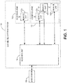
- FIG. 1 depicts an example of a DAS 100 according to aspects and features of the subject matter described herein.
- the DAS 100 can include a network of various nodes including spatially separated remote units 102a-d communicatively coupled to a head-end unit 104 for communicating with one or more base stations 106 according to one aspect.
- remote units 102a-d can connect directly to the head-end unit 104.
- the head-end unit 104 can be coupled to remote units 102a-d via a transport expansion unit or another intermediate device.
- the remote units 102a-d can provide wireless service to user equipment devices positioned in respective geographic coverage zones 110, 112.
- the head-end unit 104 can receive downlink signals from the base station 106 and transmit uplink signals to the base station 106. Any suitable communication link can be used for communication between base stations and head-end units, such as (but not limited to) a direct connection or a wireless connection.
- a direct connection can include, for example, a connection via a copper, optical fiber, or other suitable communication medium.
- the head-end unit 104 can include an external repeater or internal RF transceiver to communicate with the base station 106.
- the head-end unit 104 can combine downlink signals received from different base stations. The head-end unit 104 can transmit the combined downlink signals to one or more of the remote units 102a-d.
- Remote unit 102a can provide signal coverage in a coverage zone 110 by transmitting downlink signals to mobile communication devices in the coverage zone 110 and receiving uplink signals from the user equipment in the coverage zone 110.
- multiple remote units 102b-d can provide signal coverage in a single coverage zone 112.
- the remote units 102a-d can transmit uplink signals to the head-end unit 104.
- the head-end unit 104 can include a summer device to combine uplink signals received from remote units 102a-d for transmission to the base station 106
- a downlink signal transmitted by the base station can be repeated by the head-end unit such that copies of the downlink signal are provided to the remote units connected to the DAS.
- the remote units can then provide the copies of the common downlink signal to user devices in respective coverage zones.
- the DAS 100 (and the nodes thereof including the head-end unit 104 and the remote units 102a-d) can be configured to distribute wireless signals that are communicated using a wireless air interface that supports one or more of frequency-division duplexing (FDD) and/or time-division duplexing (TDD). Also, the DAS 100 can be configured to distribute wireless signals that are communicated using a wireless air interface that supports one or more of the multiple-input-multiple-output (MIMO), single-input-single-output (SISO), single-input-multiple-output (SIMO), and/or multiple-input-single-output (MISO) schemes. Moreover, the DAS 100 can be configured to support multiple wireless air interfaces and/or to support multiple wireless operators.
- FDD frequency-division duplexing
- TDD time-division duplexing
- MIMO multiple-input-multiple-output
- SISO single-input-single-output
- SIMO
- the DAS 100 can use either digital transport, analog transport, or combinations of digital and analog transport for communicating between the head-end unit 104 and the remote units 102a-d.
- digital transport analog transport
- digital and analog transport for communicating between the head-end unit 104 and the remote units 102a-d.
- FIGS. 2-8 The examples shown in FIGS. 2-8 are described below, for the purposes of illustration, as being implemented using digital transport. However, it is to be understood that such examples can also be implemented in DASs that use analog transport or combinations of analog and digital transport.
- digital samples indicative of the original wireless signals are communicated between the head-end unit 104 and the remote units 102a-d.
- the digital samples can be in the form of digital in-phase (I) and quadrature (Q) samples (though it is to be understood that other embodiments can use other forms of digital samples).
- Digital IQ samples can be produced from an analog wireless signal received at radio frequency (RF) by down-converting the received signal to an intermediate frequency (IF) or to baseband, digitizing the down-converted signal to produce real digital samples, and digitally down-converting the real digital samples to produce digital in-phase and quadrature samples.
- digital IQ samples can also be filtered, amplified, attenuated, and/or re-sampled or decimated to a lower sample rate.
- the digital samples can be produced in other ways.
- the portion of wireless spectrum can include, for example, a band of wireless spectrum, a sub-band of a given band of wireless spectrum, or an individual wireless carrier.
- an analog wireless signal can be produced from digital IQ samples by digitally up-converting the digital IQ samples to produce real digital samples, performing a digital-to-analog process on the real samples in order to produce an IF or baseband analog signal, and up-converting the IF or baseband analog signal to the desired RF frequency.
- the digital IQ samples can also be filtered, amplified, attenuated, and/or re-sampled or interpolated to a higher sample rate.
- the analog signal can be produced in other ways (for example, where the digital IQ samples are provided to a quadrature digital-to-analog converter that directly produces the analog IF or baseband signal).
- the head-end unit 104 can be configured to generate one or more downlink streams of digital IQ samples from one or more signals or inputs that are provided to the head-end unit 104 from the one or more base stations 106.
- each remote unit 102a-d receives one or more downlink streams of digital IQ samples produced by the head-end unit 104 and generates one or more analog downlink radio frequency wireless signals that are radiated from one or more antennas that are associated with the remote unit 102a-d.
- each downlink stream of digital IQ samples is provided to a group of one or more remote units 102a-d in order to simulcast the generated analog downlink radio frequency wireless signals from multiple locations.
- each remote unit 102a-d is configured to generate one or more uplink streams of digital IQ samples from one or more analog uplink radio frequency wireless signals received by one or more antennas associated with the remote unit 102a-d.
- the head-end unit 104 For each downlink stream of digital IQ samples that is provided from the head-end unit 104 to a respective group of one or more remote units 102a-d, the head-end unit 104 produces a corresponding uplink stream of digital IQ samples.
- Each such uplink stream is typically produced by combining individual uplink streams of digital IQ samples from each of the one or more multiple remote units 102a-d (for example, by digitally summing corresponding IQ samples from each uplink stream).
- the head-end unit 104 uses each such combined uplink stream of digital IQ samples to generate a signal or other output that is provided from the head-end unit 104 to a base station 106.
- the same downlink signals are simulcast from all of the remote units and, accordingly, the corresponding uplink signals from all of the remote units are combined together by one or more summers.
- the corresponding uplink signals from all of the remote units are combined together by one or more summers.
- other embodiments can be implemented in other ways (for example, different downlink signals can be provided to different groups of remote units, in which case the corresponding uplink signals received from each of the different groups of remote units would be separately combined together).
- the analog downlink signals transmitted by the remote units can create intermodulation byproducts that, in a DAS with no duplexer or output filter, can feed back into the receive antennas of the remote units. Due to limited transmitter/receiver isolation, the intermodulation byproducts can show up in the receive / uplink path being transmitted to the base station. The feedback intermodulation byproducts can interfere with uplink signals being received by the remote units. In a DAS system where multiple remote units are combined, the receiver band noise and intermodulation byproducts from the transmitter of the remote unit can be summed together with uplink signals from each remote unit.
- each doubling of the number of remote units can add another three decibels of intermodulation byproduct noise to the interference, reducing the overall signal to interference and noise ratio (SINR). If the receive signals are correlated, then a doubling of the number of remote units can add another six decibels to the intermodulation noise. It is desirable to reduce, attenuate, eliminate, or cancel the received intermodulation byproducts in order to increase the SINR of the overall DAS.
- an intermodulation canceler that can cancel, reduce, attenuate, or eliminate the intermodulation byproducts present in uplink signals on the receive path.
- the undesired intermodulation byproducts are similar. Due to the shouldering characteristics of spread-signal intermodulation, the transmit intermodulation byproducts tend to be clustered at one end of the receive band, such that the intermodulation signals can share the same phase variation across frequency.
- Anti-correlation can be achieved by using a gain and phase adjustment to each received signal. If the received signals vary significantly in phase and gain across the intermodulation byproducts, aspects and features disclose a frequency-dependent transfer function to manipulate the signal in order to cancel, reduce, attenuate, or eliminate the unwanted noise.
- Unwanted intermodulation byproducts in the receive band can be canceled, reduced, attenuated, or eliminated by a processing device in the head-end unit.
- the head-end unit can receive uplink signals transmitted by remote units, each uplink signal including unwanted intermodulation byproducts.
- a processing device in the head-end unit applies a transfer function to the received uplink signals in order to cancel out, reduce, attenuate, or eliminate the unwanted intermodulation byproducts.
- a transfer function can include the filtering used to modify the amplitude and gain of an input signal so that undesired intermodulation byproducts are canceled, reduced, attenuated, or eliminated from the input signal while desired uplink signals to be provided to the base station are unmodified.
- one or more DAS nodes for example, one or more head-end units, expansion or intermediary units, or remote units
- processing device 122 that digitally processes the digital IQ data that is communicated in the DAS.
- the processing device 122 can be implemented, for example, using one or more digital devices or circuits that perform digital signal processing (for example, using one or more digital signal processors or other programmable processors and/or using one or more field programmable gate arrays (FPGAs)). Each processing device 122 can be implemented in other ways.
- each processing device 122 implements one or more transfer function filters 124.
- Each transfer function filter 124 implements a variable filter that can be configured to apply a calculated transfer function to the respective input of the transfer function filter 124, the result of which is the output of that filter 124.
- Each processing device 122 also implements one or more summers 126. Each summer 126 sums the multiple inputs to that summer 126 (for example, by digitally summing corresponding IQ samples from the various inputs) to produce its output.
- Each processing device 122 also implements one or more samplers 128. Each sampler 128 captures samples of its input while passing its input through unchanged as the output of the sampler 128. The captured samples are provided to one or more transfer function calculators 130. Each processing device 202 implements one or more transfer function calculators 130. Each transfer function calculator 130 determines a transfer function based on the various samples it receives. The calculated transfer function can then be provided to one or more transfer function filters 124 in order to configure the variable filter in each such transfer function filter 124 so that it applies the calculated transfer function to the input of that transfer function 124.
- the processing device 122 also implements one or more standard DAS processing blocks 132 that perform standard digital DAS processing on the downlink and uplink IQ data (for example, as described above in connection with paragraphs [0013] - [0015]).
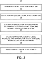
- FIG. 2 is a flow diagram illustrating one exemplary method 200 for calculating a transfer function designed to cancel, reduce, attenuate, or eliminate unwanted intermodulation byproducts received at the head-end unit.
- a remote unit is configured to generate and transmit a test reference signal (block 202). The test reference signal can be transmitted during times of low user activity in the DAS or during a DAS maintenance period so as not to interfere with normal DAS operations.
- a receive antenna at the remote unit receives feedback signals from the transmitted test reference signal (block 204), the feedback signals including the unwanted intermodulation byproducts.
- a processing device 122 in one or more nodes of the DAS can use the received feedback signal to determine an intermodulation byproduct model by comparing signal characteristics of the transmitted test signal and the received feedback signal (block 206).
- the differences in the signal characteristics between the transmitted test signal and the received feedback signal can correspond to the intermodulation byproduct model (e.g., the amount of amplitude and phase differences present in the receive signals).
- the feedback signal can be provided to the head-end unit, and a processing device 122 in the head-end unit can use the received feedback signal to determine an intermodulation byproduct model by comparing signal characteristics of the transmitted test signal and the received feedback signal.
- the processing device 122 (more specifically, one or more transfer function calculators 130 implemented using the processing device 122) then generates a transfer function that includes the inverse signal characteristics (e.g., inverse amplitude and phase) of the intermodulation byproduct model (block 208).
- a processing device 122 in one or more nodes of the DAS (such as one or more of the head-end units, remote units, or any expansion units or other intermediary nodes) applies the transfer function to at least one DAS signal in order to cancel, reduce, attenuate, or eliminate the unwanted intermodulation byproducts (block 210).
- the transfer function is applied to at least one of the uplink signals communicated from the remote units to the head end unit or at least one of the downlink signals communicated from the head end units to the remote units.
- the transfer function is applied to cancel, reduce, attenuate, or eliminate the unwanted intermodulation byproducts in the summed signals provided to the base station.
- Applying the transfer function to received signals can include, for example, filtering the received signal with the filtering characteristics specified by the transfer function.
- the transfer function can be applied, for example, prior to summing the received signals from each remote unit (as shown in FIGS. 3-6 ).
- the head-end unit can apply the transfer function to each of the transmit signals being provided from the head-end unit to each remote unit (shown in FIG. 7 ).
- the transfer function can be applied to either the receive signals or transmit signals in pairs, in small groups, or to all transmit signals or all receive signals simultaneously.
- test reference signal can be a pre-determined reference signal based on previously stored intermodulation byproduct models.
- the DAS system operator can configure the DAS with the pre-determined reference signal.
- a remote unit can generate a pilot signal at the edge of the transmit band to allow the head-end unit to determine the transfer function (at least in part due to antenna isolation variance).
- the transfer function can be updated during the normal operation of the DAS.
- the undesired intermodulation byproducts can be reduced without the use of a test reference signal.
- the transfer function can be determined by applying signal processing techniques to minimize the interference signal in the uplink received signal.
- the head-end unit can minimize like signals in the desired uplink band, as the desired signals may be different/non-correlated at each remote unit, while the undesired transmit intermodulation can be the same at each receiver. For example, if transmit signals from non-adjacent remote units are summed together, the desired signals from each remote unit can be non-correlated while the undesired intermodulation byproducts may be similar and cancellable.
- the desired signals from multiple remote units may be common or otherwise correlated (e.g., if two adjacent remote units receive uplink signals from a single mobile device).
- the head-end unit may determine, for example, in which locations in the band the undesired signals may fall (from the original transmit signals) and determine the cancellation by minimizing signal/noise in the bandwidth that has the undesired signals.
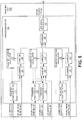
- the head-end unit 300 can include multiple transfer function filters 124, each transfer function filter 124 receiving uplink signals from a different respective remote unit.
- the received signals can be provided to a summer 126 included in the head-end unit 300.
- a sampler 128 in the head-end unit 300 can then sample the summed signals, generating sampled signals provided to a transfer function calculator 130.
- the transfer function calculator 130 can determine the transfer functions for each transfer function filter 124.
- each transfer function filter 124 can apply the transfer function calculated by the transfer function calculator 130, cancelling, reducing, attenuating, or eliminating the unwanted intermodulation byproducts before the uplink signals are summed by the summer 126.
- FIGS. 4-6 depict additional configurations for a head-end unit for cancelling, reducing, attenuating, or eliminating unwanted intermodulation byproducts according to certain aspects.
- FIG. 4 depicts a head-end unit 400 configured such that summation and cancellation, reduction, attenuation, or elimination of the unwanted intermodulation byproducts can be performed in small groups of remote unit inputs (e.g., two or three per group).
- the minimized signals can then be summed together at a summer 126 before being provided to a DAS signal processing block 132.
- the DAS signal processing block 132 can then perform standard digital DAS processing on the downlink and uplink IQ data (for example, as described above in connection with paragraphs [0013] - [0015]).
- FIG. 5 depicts a block diagram of a head-end unit 500 calculating and applying a transfer function to n-1 of the total number of received signals being summed.
- the head-end unit 500 can include multiple transfer function filter 124, each transfer function filter 124 receiving uplink signals from a different respective remote unit.
- the received signals can be provided to a summer 126 included in the head-end unit 500.
- a sampler 128 in the head-end unit 500 can then sample the summed signals, generating sampled signals provided to a transfer function calculator 130.
- the transfer function calculator 130 can determine the transfer functions for each transfer function filter 124.
- each transfer function filter 124 can apply the transfer function calculated by the transfer function calculator 130, cancelling, reducing, attenuating, or eliminating the unwanted intermodulation byproducts before the uplink signals are summed by the summer 126.
- FIG. 6 depicts a head-end unit 600 configured such that each received signal from the respective remote units is provided to a respective sampler 128.
- the samples of the individual received signals can be provided to the transfer function calculator 130.
- the transfer function calculator 130 can extract the reference signals communicated in each received signal (by processing the associated digital IQ data) in order to determine the individual transfer functions/non-linear models of the receive isolation path through the remote units.
- the transfer function calculator 130 provides the calculated transfer functions to the respective transfer function filters 124, which can apply the transfer functions to the received uplink signals from each remote unit. Undesired intermodulation byproducts can be canceled, reduced, attenuated, or eliminated as they are being summed by the summer 126.
- the head-end unit can apply the transfer function to each of the transmit signals being provided from the head-end unit to each remote unit.
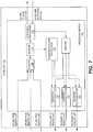
- FIG. 7 depicts one example of a head-end unit 700 configured so that a downlink signal provided to each remote unit is filtered by a transfer function filter 124.
- the transfer function calculator 130 calculates the transfer functions that are applied to the transfer functions 124 based on samples made by samplers 128 in the uplink signal path.
- a remote unit 800 includes a processing device 122 that can be configured such that each received signal transmitted from that remote unit to the head-end unit (either directly or via an expansion unit or other intermediary unit) is first sampled by a sampler 128.
- the samples of the received signal can be provided to a transfer function calculator 130 in the remote node 800.
- the transfer function calculator 130 can extract the reference signals communicated in each received signal (by processing the associated digital IQ data) in order to determine the transfer function/non-linear model of the receive isolation path through the remote unit.
- the transfer function calculator 130 provides the calculated transfer function to a transfer function filter 124, which can apply the transfer function to the received uplink signal, thereby cancelling, reducing, attenuating, or eliminating the undesired intermodulation byproducts before the uplink signal is transmitted from the remote unit to the head-end unit.
- a node can be configured to digitize the analog signals to produce digital IQ data from the analog signals (for example, in the manner described above).
- the resulting digital IQ data then be used to calculate and apply a transfer function (using, for example, digital signal processing techniques similar to the ones described above) in order to cancel, reduce, attenuate, or eliminate undesired intermodulation byproducts.
- the resulting processed digital IQ data can then be used to produce suitable analog signals, which can then be transported as in conventional analog DAS systems.
Landscapes
- Engineering & Computer Science (AREA)
- Computer Networks & Wireless Communication (AREA)
- Signal Processing (AREA)
- Physics & Mathematics (AREA)
- Electromagnetism (AREA)
- Mobile Radio Communication Systems (AREA)
- Noise Elimination (AREA)
Claims (15)
- Verteiltes Antennensystem (Distributed Antenna System ― DAS) (100), das Folgendes umfasst:eine Vielzahl von Knoten, die Folgendes beinhalten:eine Kopfstelleneinheit (104); undeine Vielzahl von Ferneinheiten (102), die kommunikativ mit der Kopfstelleneinheit (104) gekoppelt sind;wobei die Kopfstelleneinheit (104) dazu konfiguriert ist, Uplink-Empfangssignale von Ferneinheiten (102) zu empfangen, die Signale in einem Abdeckungsbereich (110, 112) drahtlos senden-empfangen;wobei die Kopfstelleneinheit (104) eine oder mehrere Summierungsvorrichtungen beinhaltet, die dazu konfiguriert sind, zwei oder mehrere der Uplink-Empfangssignale zu summieren, um ein summiertes Uplink-Empfangssignal zu erzeugen; undwobei mindestens einer der Knoten des DAS (100) eine Verarbeitungsvorrichtung (122) beinhaltet, die eine oder mehrere Transferfunktionsberechnungseinrichtungen (130) beinhaltet, die dazu konfiguriert sind, eine Transferfunktion auf Grundlage von Abtastwerten des summierten Uplink-Empfangssignals und/oder des von einem oder mehreren Abtasteinrichtungen (128) in einem Uplink-Signalpfad empfangenen Uplink-Empfangssignals zu bestimmen, wobei die eine oder mehreren Transferfunktionsberechnungseinrichtungen (130) dazu konfiguriert sind, die bestimmte Transferfunktion einem oder mehreren Transferfunktionsfiltern (124) bereitzustellen, um ein variables Filter jedes der einen oder mehreren Transferfunktionsfilter (124) zu konfigurieren, um die bestimmte Transferfunktion auf Signale in dem DAS (100) in dem Uplink-Signalpfad vor der Summierung durch die eine oder mehreren Summierungsvorrichtungen oder in einem Downlink-Signalpfad anzuwenden, wobei die Anwendung der bestimmten Transferfunktion Intermodulationsnebenprodukte in dem summierten Uplink-Empfangssignal unterdrückt, verringert, dämpft oder eliminiert.
- DAS (100) nach Anspruch 1, wobei die Verarbeitungsvorrichtung (122) dazu konfiguriert ist, die Transferfunktion durch Vergleichen eines von einer Ferneinheit (102) übertragenen Testreferenzsignals mit einem Empfangsfeedbacksignal zu bestimmen, um eine inverse Signalkennlinie unerwünschter Intermodulationsnebenprodukte in dem Empfangsfeedbacksignal zu bestimmen.
- DAS (100) nach Anspruch 1, wobei die Transferfunktion durch das Minimieren gleicher Signale in einem gewünschten Uplink-Band des Uplink-Empfangssignals bestimmt wird.
- DAS (100) nach Anspruch 1, wobei die Vielzahl von Ferneinheiten dazu konfiguriert ist, Downlink-Signale zu übertragen, wobei die Transferfunktion durch Minimieren eines spezifischen Abschnitts eines Uplink-Bands in den Uplink-Empfangssignalen bestimmt wird, von denen durch eine Analyse der übertragenen Downlink-Signale bestimmt wurde, dass sie Intermodulationsrauschen aufweisen.
- Verfahren (200), das in einem verteilten Antennensystem, DAS, ausgeführt wird, das eine Vielzahl von Knoten umfasst, die eine Kopfstelleneinheit beinhalten, die kommunikativ mit einer Vielzahl von Ferneinheiten gekoppelt ist, wobei das Verfahren Folgendes umfasst:Übertragen (202) eines Testreferenzsignals von einer Ferneinheit der Vielzahl von Ferneinheiten;Empfangen (204) eines Feedbacksignals von dem Testreferenzsignal an einer Empfangsantenne der Ferneinheit;Berechnen (208) einer Transferfunktion aus dem Testreferenzsignal und dem Feedbacksignal, um Intermodulationsnebenprodukte in nachfolgenden Signalen, die von der Kopfstelleneinheit empfangen werden, zu unterdrücken, zu verringern, zu dämpfen oder zu eliminieren; undKonfigurieren eines variablen Filters eines Transferfunktionsfilters, um die berechnete Transferfunktion auf Signale des DAS in dem Uplink-Signalpfad vor der Summierung durch eine oder mehrere Summierungseinrichtungen (126) in dem Uplink-Signalpfad oder in einem Downlink-Signalpfad anzuwenden, wobei die Anwendung der berechneten Transferfunktion Intermodulationsnebenprodukte unterdrückt verringert, dämpft oder eliminiert.
- Verfahren (200) nach Anspruch 5, das ferner das Bereitstellen des Testreferenzsignals und des Feedbacksignals an die Kopfstelleneinheit zur Verwendung bei der Berechnung der Transferfunktion umfasst, um Intermodulationsnebenprodukte in nachfolgenden Signalen, die von der Kopfstelleneinheit empfangen werden, zu unterdrücken, zu verringern, zu dämpfen oder zu eliminieren.
- Verfahren (200) nach Anspruch 5, wobei das Berechnen der Transferfunktion aus dem Testreferenzsignal und dem Feedbacksignal, um Intermodulationsnebenprodukte in nachfolgenden Signalen, die von der Kopfstelleneinheit empfangen werden, zu unterdrücken, zu verringern, zu dämpfen oder zu eliminieren, Folgendes umfasst:
Vergleichen des Testreferenzsignals mit dem Empfangsfeedbacksignal, um eine inverse Signalkennlinie unerwünschter Intermodulationsnebenprodukte in dem Feedbacksignal zu bestimmen. - DAS (100) nach Anspruch 2 oder Verfahren (200) nach Anspruch 7, wobei die inverse Signalkennlinie eine Phasenverschiebung und eine Amplitudenverschiebung beinhaltet.
- Verfahren (200) nach Anspruch 5, wobei die Transferfunktion durch Minimieren der gleichen Signale in einem gewünschten Uplink-Band des Uplink-Empfangssignals berechnet wird.
- Verfahren (200) nach Anspruch 5, das ferner das Übertragen von Downlink-Signalen von der Ferneinheit umfasst;
wobei das Berechnen der Transferfunktion aus dem Testreferenzsignal und dem Feedbacksignal, um Intermodulationsnebenprodukte in nachfolgenden Signalen, die von der Kopfstelleneinheit empfangen werden, zu unterdrücken, zu verringern, zu dämpfen oder zu eliminieren, Folgendes umfasst:
Minimieren eines spezifischen Abschnitts eines Uplink-Bands in Uplink-Empfangssignalen, von denen durch eine Analyse der übertragenen Downlink-Signale bestimmt wurde, dass sie Intermodulationsrauschen aufweisen. - DAS (100) nach Anspruch 1 oder Verfahren (200) nach Anspruch 5, wobei die Transferfunktion vor der Summierung auf zwei oder mehrere Uplink-Empfangssignale angewendet wird.
- DAS (100) nach Anspruch 1 oder Verfahren (200) nach Anspruch 5, wobei die Transferfunktion auf eines oder mehrere der Uplink-Empfangssignale in der Kopfstelleneinheit angewendet wird.
- DAS (100) nach Anspruch 1 oder Verfahren (200) nach Anspruch 5, wobei die Transferfunktion auf eines oder mehrere Signale in mindestens einer der Ferneinheiten angewendet wird.
- DAS (100) nach Anspruch 1 oder Verfahren (200) nach Anspruch 5, wobei die Transferfunktion auf eines oder mehrere Signale in einer Erweiterungseinheit angewendet wird, die verwendet wird, um mindestens eine Ferneinheit kommunikativ mit der Kopfstelleneinheit zu koppeln.
- DAS (100) nach Anspruch 1 oder Verfahren (200) nach Anspruch 5, wobei die Transferfunktion in einem Downlink-Signalpfad von mindestens einem Knoten des DAS auf mindestens ein Übertragungssignal, das über das DAS kommuniziert wird, angewendet wird.
Applications Claiming Priority (2)
| Application Number | Priority Date | Filing Date | Title |
|---|---|---|---|
| US201562128189P | 2015-03-04 | 2015-03-04 | |
| PCT/US2016/020570 WO2016141120A1 (en) | 2015-03-04 | 2016-03-03 | Intermodulation byproduct cancellation in one or more nodes of a distributed antenna system |
Publications (3)
| Publication Number | Publication Date |
|---|---|
| EP3266128A1 EP3266128A1 (de) | 2018-01-10 |
| EP3266128A4 EP3266128A4 (de) | 2018-10-24 |
| EP3266128B1 true EP3266128B1 (de) | 2021-11-10 |
Family
ID=56848618
Family Applications (1)
| Application Number | Title | Priority Date | Filing Date |
|---|---|---|---|
| EP16759453.0A Active EP3266128B1 (de) | 2015-03-04 | 2016-03-03 | Intermodulationsnebenproduktunterdrückung in einem oder mehreren knoten eines verteilten antennensystems |
Country Status (3)
| Country | Link |
|---|---|
| US (2) | US10348424B2 (de) |
| EP (1) | EP3266128B1 (de) |
| WO (1) | WO2016141120A1 (de) |
Families Citing this family (7)
| Publication number | Priority date | Publication date | Assignee | Title |
|---|---|---|---|---|
| EP3266128B1 (de) * | 2015-03-04 | 2021-11-10 | Commscope Technologies LLC | Intermodulationsnebenproduktunterdrückung in einem oder mehreren knoten eines verteilten antennensystems |
| EP3284227B1 (de) * | 2015-04-16 | 2023-04-05 | Andrew Wireless Systems GmbH | Uplink-signalkombinierer für mobilfunksignalverteilungssysteme mit ethernetdatennetzwerken |
| US10523250B2 (en) * | 2016-09-06 | 2019-12-31 | Apple Inc. | Systems and methods for mitigating intermodulation effects |
| IT201700055080A1 (it) | 2017-05-22 | 2018-11-22 | Teko Telecom S R L | Sistema di comunicazione wireless e relativo metodo per il trattamento di dati fronthaul di uplink |
| CN110557183A (zh) * | 2018-05-30 | 2019-12-10 | 上海华为技术有限公司 | 一种信号处理方法、装置、分布式天线系统及存储介质 |
| JP2022552941A (ja) * | 2019-09-26 | 2022-12-21 | コムスコープ テクノロジーズ リミティド ライアビリティ カンパニー | 分散アンテナシステムのマスタユニットのためのパッシブバックプレーンアーキテクチャ |
| CN110768733B (zh) * | 2019-11-26 | 2021-12-14 | 武汉虹信科技发展有限责任公司 | 集成滤波器的大规模阵列天线的测试方法及装置 |
Family Cites Families (63)
| Publication number | Priority date | Publication date | Assignee | Title |
|---|---|---|---|---|
| US20010033196A1 (en) * | 2000-01-20 | 2001-10-25 | National Instruments Corporation | State variable filter including a programmable variable resistor |
| US6801767B1 (en) * | 2001-01-26 | 2004-10-05 | Lgc Wireless, Inc. | Method and system for distributing multiband wireless communications signals |
| US20040248544A1 (en) * | 2001-08-06 | 2004-12-09 | Christian Lamothe | Portable receiver with two antennae |
| US20040157645A1 (en) * | 2003-02-12 | 2004-08-12 | Smith Adrian David | System and method of operation an array antenna in a distributed wireless communication network |
| US20050176368A1 (en) * | 2003-03-07 | 2005-08-11 | Spotwave Wireless Inc. | Distributed adaptive repeater system |
| DE10345239B4 (de) * | 2003-09-29 | 2013-09-05 | Epcos Ag | Mit Oberflächenwellen arbeitender Wandler |
| JP4347074B2 (ja) * | 2004-01-27 | 2009-10-21 | シャープ株式会社 | アクティブフィルタ |
| US7848717B2 (en) * | 2004-12-21 | 2010-12-07 | Zte Corporation | Method and system for out of band predistortion linearization |
| US7565393B2 (en) * | 2005-06-29 | 2009-07-21 | Intel Corporation | Discrete time filter having gain for digital sampling receivers |
| US7482863B2 (en) * | 2005-08-12 | 2009-01-27 | Roberts Retrovalve, Inc. | Expanded performance and functions for vacuum tube replacement devices |
| US7564305B2 (en) * | 2007-11-12 | 2009-07-21 | Tellabs Operations, Inc. | System and method for self-cancellation of Nth-order intermodulation products |
| US9160310B2 (en) * | 2008-04-30 | 2015-10-13 | Scott R. Velazquez | Linearity compensator for removing nonlinear distortion |
| US8811974B2 (en) * | 2008-12-30 | 2014-08-19 | Telefonaktiebolaget L M Ericsson (Publ) | Coordinated multipoint wireless communication |
| US8897717B2 (en) * | 2010-07-28 | 2014-11-25 | Honeywell International Inc. | Dual-feed antenna array with integral comparison circuit for phase and amplitude calibration |
| WO2012054121A2 (en) * | 2010-07-30 | 2012-04-26 | Tufts University/Trustees Of Tufts College | Silk-based biophotonic sensors |
| JP5644396B2 (ja) * | 2010-08-06 | 2014-12-24 | 株式会社明電舎 | 電力変換装置の高調波電流抑制装置および高調波電流抑制方法 |
| US8416836B2 (en) * | 2010-09-29 | 2013-04-09 | Siklu Communication ltd. | Using OFDM to correct distortions in ultra-wide-band radios operating over flat millimeter-wave channels |
| SG189467A1 (en) * | 2010-10-20 | 2013-05-31 | Aviat Networks Inc | Systems and methods for improved power yield and linearization in radio frequency transmitters |
| JP5265657B2 (ja) * | 2010-12-27 | 2013-08-14 | シャープ株式会社 | 基地局装置、端末装置、通信システムおよび通信方法 |
| EP3422585B1 (de) * | 2011-06-01 | 2021-11-10 | CommScope Technologies LLC | Verteiltes breitband-antennensystem mit duplexerlosem isolator-subsystem |
| CA2838740A1 (en) * | 2011-06-13 | 2012-12-20 | Adc Telecommunications, Inc. | Distributed antenna system architectures |
| EP3190728B1 (de) * | 2011-09-15 | 2022-03-09 | Andrew Wireless Systems GmbH | Konfiguration eines subsystems für telekommunikationssysteme |
| EP2661828B1 (de) * | 2011-09-16 | 2016-03-23 | Andrew Wireless Systems GmbH | Integriertes intermodulationserkennungssubsystem für telekommunikationssysteme |
| US8867451B2 (en) * | 2012-02-02 | 2014-10-21 | Andrew Llc | Optimized telecommunications distribution system |
| GB2510997B (en) * | 2012-05-21 | 2014-11-05 | Aceaxis Ltd | Detection of Intermodulation Products in a Wireless Network |
| CN104364638A (zh) * | 2012-05-30 | 2015-02-18 | 通用电气公司 | 用于对材料特性进行测量的传感器设备 |
| US8787429B2 (en) * | 2012-06-19 | 2014-07-22 | Andrew Llc | Communication system with channel compensating equalizer |
| US8953724B2 (en) * | 2012-06-27 | 2015-02-10 | Andrew Llc | Canceling narrowband interfering signals in a distributed antenna system |
| US9179321B2 (en) * | 2012-08-09 | 2015-11-03 | Axell Wireless Ltd. | Digital capacity centric distributed antenna system |
| US8837559B2 (en) * | 2012-08-16 | 2014-09-16 | Andrew Wireless Systems Gmbh | Reducing distortion in repeaters for OFDM signals |
| US20140064348A1 (en) * | 2012-09-06 | 2014-03-06 | Andrew Llc | Digital Post-Distortion Compensation in Telecommunication Systems |
| EP3614561A1 (de) * | 2012-09-14 | 2020-02-26 | Andrew Wireless Systems GmbH | Detektion der integrität eines uplink-pfades in verteilten antennensystemen |
| WO2014053149A1 (en) * | 2012-10-05 | 2014-04-10 | Andrew Wireless Systems Gmbh | Capacity optimization sub-system for distributed antenna system |
| US9407302B2 (en) * | 2012-12-03 | 2016-08-02 | Intel Corporation | Communication device, mobile terminal, method for requesting information and method for providing information |
| US8917792B2 (en) * | 2012-12-12 | 2014-12-23 | Motorola Mobility Llc | Method and apparatus for the cancellation of intermodulation and harmonic distortion in a baseband receiver |
| EP2945447A4 (de) * | 2013-01-09 | 2016-08-03 | Sharp Kk | Endgerätevorrichtung und basisstationsvorrichtung |
| US9065523B2 (en) * | 2013-02-16 | 2015-06-23 | Cable Television Laboratories, Inc. | Multiple-input multiple-output (MIMO) communication system |
| KR102089437B1 (ko) | 2013-03-07 | 2020-04-16 | 삼성전자 주식회사 | 무선 통신 시스템에서 간섭 제어 방법 및 장치 |
| GB2511865B (en) * | 2013-03-15 | 2015-07-01 | Aceaxis Ltd | Processing interference in a wireless network |
| US9319916B2 (en) * | 2013-03-15 | 2016-04-19 | Isco International, Llc | Method and appartus for signal interference processing |
| US20140293894A1 (en) * | 2013-03-28 | 2014-10-02 | Coming Optical Communications Wireless, Ltd. | Distributing dynamically frequency-shifted intermediate frequency (if) radio frequency (rf) communications signals in distributed antenna systems (dass), and related components, systems, and methods |
| EP3008937B1 (de) * | 2013-06-12 | 2020-05-27 | Andrew Wireless Systems GmbH | Optimierungssystem für ein verteiltes antennensystem |
| GB201313066D0 (en) * | 2013-07-22 | 2013-09-04 | Aceaxis Ltd | Processing interference in a wireless network |
| EP3487078B1 (de) * | 2013-10-03 | 2022-05-11 | Andrew Wireless Systems GmbH | Schnittstellenvorrichtung für leistungsverwaltung und lastabschluss in einem verteilten antennensystem |
| US9980269B2 (en) * | 2014-01-30 | 2018-05-22 | Commscope Technologies Llc | Optimizing power allocation in signal distribution systems using variable and static gains |
| US10251154B2 (en) * | 2014-02-18 | 2019-04-02 | Commscope Technologies Llc | Distributed antenna system measurement receiver |
| WO2015160777A1 (en) * | 2014-04-15 | 2015-10-22 | Commscope Technologies Llc | Wideband remote unit for distributed antenna system |
| GB2526787B (en) * | 2014-05-29 | 2016-11-23 | Aceaxis Ltd | Processing of passive intermodulation detection results |
| EP3198755B1 (de) * | 2014-09-23 | 2020-12-23 | Axell Wireless Ltd. | Automatische abbildung und handhabung von passiver intermodulation (pim) und anderen uplink-interferenzen in digital verteilten antennensystemen |
| GB2531357B (en) * | 2014-10-17 | 2019-01-09 | Aceaxis Ltd | Mitigating passive intermodulation interference in a wireless network |
| KR102075405B1 (ko) * | 2014-12-30 | 2020-02-11 | 주식회사 쏠리드 | 기지국 신호 정합 장치 |
| US20160249365A1 (en) * | 2015-02-19 | 2016-08-25 | Corning Optical Communications Wireless Ltd. | Offsetting unwanted downlink interference signals in an uplink path in a distributed antenna system (das) |
| EP3266128B1 (de) * | 2015-03-04 | 2021-11-10 | Commscope Technologies LLC | Intermodulationsnebenproduktunterdrückung in einem oder mehreren knoten eines verteilten antennensystems |
| EP3799317B1 (de) * | 2015-04-24 | 2022-11-16 | Andrew Wireless Systems GmbH | Untersystem zur unterdrückung von zirkulatorverzerrungen |
| KR102128800B1 (ko) * | 2015-04-24 | 2020-07-02 | 주식회사 쏠리드 | 분산 안테나 시스템 |
| CN107810606B (zh) * | 2015-05-01 | 2020-09-08 | 安德鲁无线系统有限公司 | 用于电信系统的非双工器体系结构 |
| US10531330B2 (en) * | 2015-05-20 | 2020-01-07 | Andrew Wireless Systems Gmbh | Frame start optimizing in telecommunications systems |
| EP3298708B1 (de) * | 2015-05-22 | 2020-06-10 | CommScope Technologies LLC | Validierungsuntersystem für telekommunikationssystem |
| EP3311497B1 (de) * | 2015-06-16 | 2021-08-04 | Commscope Technologies LLC | Funkfrequenzsender |
| US20160380668A1 (en) * | 2015-06-26 | 2016-12-29 | Fujitsu Limited | Communication device and receiving method |
| EP3572981A1 (de) * | 2015-07-16 | 2019-11-27 | Andrew Wireless Systems GmbH | System zur bestimmung des layouts und der absoluten und relativen positionen von elementen in einem verteilten antennensystem sowie zur verwendung der elemente zur messung |
| US10345438B2 (en) * | 2016-09-19 | 2019-07-09 | Commscope Technologies Llc | Determining distance to source of passive intermodulation product (PIM) in a distributed base station |
| US10601529B2 (en) * | 2017-01-24 | 2020-03-24 | Corning Optical Communications LLC | Suppressing an uplink radio frequency (RF) interference signal(s) in a remote unit in a wireless distribution system (WDS) using a correction signal(s) relative to the uplink RF interference signal(s) |
-
2016
- 2016-03-03 EP EP16759453.0A patent/EP3266128B1/de active Active
- 2016-03-03 WO PCT/US2016/020570 patent/WO2016141120A1/en not_active Ceased
- 2016-03-03 US US15/555,373 patent/US10348424B2/en active Active
-
2019
- 2019-07-08 US US16/504,437 patent/US10644814B2/en active Active
Non-Patent Citations (1)
| Title |
|---|
| None * |
Also Published As
| Publication number | Publication date |
|---|---|
| US20180048402A1 (en) | 2018-02-15 |
| US10644814B2 (en) | 2020-05-05 |
| US20190334639A1 (en) | 2019-10-31 |
| WO2016141120A1 (en) | 2016-09-09 |
| US10348424B2 (en) | 2019-07-09 |
| EP3266128A4 (de) | 2018-10-24 |
| EP3266128A1 (de) | 2018-01-10 |
Similar Documents
| Publication | Publication Date | Title |
|---|---|---|
| US10644814B2 (en) | Intermodulation byproduct cancellation in one or more nodes of a distributed antenna system | |
| US10601378B2 (en) | Distributed antenna system architectures | |
| US11283530B2 (en) | Wideband remote unit for distributed antenna system | |
| EP2194663A2 (de) | Funkrelaisvorrichtung und -verfahren | |
| CN104935540B (zh) | 一种同时同频全双工极限自干扰抵消方法 | |
| US20220345193A1 (en) | Systems and methods for reconfigurable repeaters for wireless telecommunications | |
| CN105763220A (zh) | 具有非双工器隔离子系统的宽带分布式天线系统 | |
| EP4107864A1 (de) | Systeme und verfahren zur digitalen interferenzunterdrückung | |
| US10886964B2 (en) | Non-duplexer architectures for telecommunications system | |
| EP3275095B1 (de) | Digitales repeater syytem | |
| KR20170070927A (ko) | 이동통신 시스템의 필터 장치 |
Legal Events
| Date | Code | Title | Description |
|---|---|---|---|
| STAA | Information on the status of an ep patent application or granted ep patent |
Free format text: STATUS: THE INTERNATIONAL PUBLICATION HAS BEEN MADE |
|
| PUAI | Public reference made under article 153(3) epc to a published international application that has entered the european phase |
Free format text: ORIGINAL CODE: 0009012 |
|
| STAA | Information on the status of an ep patent application or granted ep patent |
Free format text: STATUS: REQUEST FOR EXAMINATION WAS MADE |
|
| 17P | Request for examination filed |
Effective date: 20170608 |
|
| AK | Designated contracting states |
Kind code of ref document: A1 Designated state(s): AL AT BE BG CH CY CZ DE DK EE ES FI FR GB GR HR HU IE IS IT LI LT LU LV MC MK MT NL NO PL PT RO RS SE SI SK SM TR |
|
| AX | Request for extension of the european patent |
Extension state: BA ME |
|
| DAV | Request for validation of the european patent (deleted) | ||
| DAX | Request for extension of the european patent (deleted) | ||
| REG | Reference to a national code |
Ref country code: DE Ref legal event code: R079 Ref document number: 602016066032 Country of ref document: DE Free format text: PREVIOUS MAIN CLASS: H04B0017110000 Ipc: H04B0017000000 |
|
| A4 | Supplementary search report drawn up and despatched |
Effective date: 20180920 |
|
| RIC1 | Information provided on ipc code assigned before grant |
Ipc: H04B 1/10 20060101ALI20180915BHEP Ipc: H04B 17/14 20150101ALI20180915BHEP Ipc: H04B 17/12 20150101ALI20180915BHEP Ipc: H04B 17/24 20150101ALI20180915BHEP Ipc: H04B 17/00 20150101AFI20180915BHEP Ipc: H04B 7/04 20170101ALI20180915BHEP |
|
| STAA | Information on the status of an ep patent application or granted ep patent |
Free format text: STATUS: EXAMINATION IS IN PROGRESS |
|
| 17Q | First examination report despatched |
Effective date: 20190527 |
|
| GRAP | Despatch of communication of intention to grant a patent |
Free format text: ORIGINAL CODE: EPIDOSNIGR1 |
|
| STAA | Information on the status of an ep patent application or granted ep patent |
Free format text: STATUS: GRANT OF PATENT IS INTENDED |
|
| INTG | Intention to grant announced |
Effective date: 20210708 |
|
| GRAS | Grant fee paid |
Free format text: ORIGINAL CODE: EPIDOSNIGR3 |
|
| GRAA | (expected) grant |
Free format text: ORIGINAL CODE: 0009210 |
|
| STAA | Information on the status of an ep patent application or granted ep patent |
Free format text: STATUS: THE PATENT HAS BEEN GRANTED |
|
| AK | Designated contracting states |
Kind code of ref document: B1 Designated state(s): AL AT BE BG CH CY CZ DE DK EE ES FI FR GB GR HR HU IE IS IT LI LT LU LV MC MK MT NL NO PL PT RO RS SE SI SK SM TR |
|
| REG | Reference to a national code |
Ref country code: GB Ref legal event code: FG4D |
|
| REG | Reference to a national code |
Ref country code: AT Ref legal event code: REF Ref document number: 1447047 Country of ref document: AT Kind code of ref document: T Effective date: 20211115 Ref country code: CH Ref legal event code: EP |
|
| REG | Reference to a national code |
Ref country code: DE Ref legal event code: R096 Ref document number: 602016066032 Country of ref document: DE |
|
| REG | Reference to a national code |
Ref country code: IE Ref legal event code: FG4D |
|
| REG | Reference to a national code |
Ref country code: LT Ref legal event code: MG9D |
|
| REG | Reference to a national code |
Ref country code: NL Ref legal event code: MP Effective date: 20211110 |
|
| REG | Reference to a national code |
Ref country code: AT Ref legal event code: MK05 Ref document number: 1447047 Country of ref document: AT Kind code of ref document: T Effective date: 20211110 |
|
| PG25 | Lapsed in a contracting state [announced via postgrant information from national office to epo] |
Ref country code: RS Free format text: LAPSE BECAUSE OF FAILURE TO SUBMIT A TRANSLATION OF THE DESCRIPTION OR TO PAY THE FEE WITHIN THE PRESCRIBED TIME-LIMIT Effective date: 20211110 Ref country code: LT Free format text: LAPSE BECAUSE OF FAILURE TO SUBMIT A TRANSLATION OF THE DESCRIPTION OR TO PAY THE FEE WITHIN THE PRESCRIBED TIME-LIMIT Effective date: 20211110 Ref country code: FI Free format text: LAPSE BECAUSE OF FAILURE TO SUBMIT A TRANSLATION OF THE DESCRIPTION OR TO PAY THE FEE WITHIN THE PRESCRIBED TIME-LIMIT Effective date: 20211110 Ref country code: BG Free format text: LAPSE BECAUSE OF FAILURE TO SUBMIT A TRANSLATION OF THE DESCRIPTION OR TO PAY THE FEE WITHIN THE PRESCRIBED TIME-LIMIT Effective date: 20220210 Ref country code: AT Free format text: LAPSE BECAUSE OF FAILURE TO SUBMIT A TRANSLATION OF THE DESCRIPTION OR TO PAY THE FEE WITHIN THE PRESCRIBED TIME-LIMIT Effective date: 20211110 |
|
| PG25 | Lapsed in a contracting state [announced via postgrant information from national office to epo] |
Ref country code: IS Free format text: LAPSE BECAUSE OF FAILURE TO SUBMIT A TRANSLATION OF THE DESCRIPTION OR TO PAY THE FEE WITHIN THE PRESCRIBED TIME-LIMIT Effective date: 20220310 Ref country code: SE Free format text: LAPSE BECAUSE OF FAILURE TO SUBMIT A TRANSLATION OF THE DESCRIPTION OR TO PAY THE FEE WITHIN THE PRESCRIBED TIME-LIMIT Effective date: 20211110 Ref country code: PT Free format text: LAPSE BECAUSE OF FAILURE TO SUBMIT A TRANSLATION OF THE DESCRIPTION OR TO PAY THE FEE WITHIN THE PRESCRIBED TIME-LIMIT Effective date: 20220310 Ref country code: PL Free format text: LAPSE BECAUSE OF FAILURE TO SUBMIT A TRANSLATION OF THE DESCRIPTION OR TO PAY THE FEE WITHIN THE PRESCRIBED TIME-LIMIT Effective date: 20211110 Ref country code: NO Free format text: LAPSE BECAUSE OF FAILURE TO SUBMIT A TRANSLATION OF THE DESCRIPTION OR TO PAY THE FEE WITHIN THE PRESCRIBED TIME-LIMIT Effective date: 20220210 Ref country code: NL Free format text: LAPSE BECAUSE OF FAILURE TO SUBMIT A TRANSLATION OF THE DESCRIPTION OR TO PAY THE FEE WITHIN THE PRESCRIBED TIME-LIMIT Effective date: 20211110 Ref country code: LV Free format text: LAPSE BECAUSE OF FAILURE TO SUBMIT A TRANSLATION OF THE DESCRIPTION OR TO PAY THE FEE WITHIN THE PRESCRIBED TIME-LIMIT Effective date: 20211110 Ref country code: HR Free format text: LAPSE BECAUSE OF FAILURE TO SUBMIT A TRANSLATION OF THE DESCRIPTION OR TO PAY THE FEE WITHIN THE PRESCRIBED TIME-LIMIT Effective date: 20211110 Ref country code: GR Free format text: LAPSE BECAUSE OF FAILURE TO SUBMIT A TRANSLATION OF THE DESCRIPTION OR TO PAY THE FEE WITHIN THE PRESCRIBED TIME-LIMIT Effective date: 20220211 Ref country code: ES Free format text: LAPSE BECAUSE OF FAILURE TO SUBMIT A TRANSLATION OF THE DESCRIPTION OR TO PAY THE FEE WITHIN THE PRESCRIBED TIME-LIMIT Effective date: 20211110 |
|
| PG25 | Lapsed in a contracting state [announced via postgrant information from national office to epo] |
Ref country code: SM Free format text: LAPSE BECAUSE OF FAILURE TO SUBMIT A TRANSLATION OF THE DESCRIPTION OR TO PAY THE FEE WITHIN THE PRESCRIBED TIME-LIMIT Effective date: 20211110 Ref country code: SK Free format text: LAPSE BECAUSE OF FAILURE TO SUBMIT A TRANSLATION OF THE DESCRIPTION OR TO PAY THE FEE WITHIN THE PRESCRIBED TIME-LIMIT Effective date: 20211110 Ref country code: RO Free format text: LAPSE BECAUSE OF FAILURE TO SUBMIT A TRANSLATION OF THE DESCRIPTION OR TO PAY THE FEE WITHIN THE PRESCRIBED TIME-LIMIT Effective date: 20211110 Ref country code: EE Free format text: LAPSE BECAUSE OF FAILURE TO SUBMIT A TRANSLATION OF THE DESCRIPTION OR TO PAY THE FEE WITHIN THE PRESCRIBED TIME-LIMIT Effective date: 20211110 Ref country code: DK Free format text: LAPSE BECAUSE OF FAILURE TO SUBMIT A TRANSLATION OF THE DESCRIPTION OR TO PAY THE FEE WITHIN THE PRESCRIBED TIME-LIMIT Effective date: 20211110 Ref country code: CZ Free format text: LAPSE BECAUSE OF FAILURE TO SUBMIT A TRANSLATION OF THE DESCRIPTION OR TO PAY THE FEE WITHIN THE PRESCRIBED TIME-LIMIT Effective date: 20211110 |
|
| REG | Reference to a national code |
Ref country code: DE Ref legal event code: R097 Ref document number: 602016066032 Country of ref document: DE |
|
| PLBE | No opposition filed within time limit |
Free format text: ORIGINAL CODE: 0009261 |
|
| STAA | Information on the status of an ep patent application or granted ep patent |
Free format text: STATUS: NO OPPOSITION FILED WITHIN TIME LIMIT |
|
| 26N | No opposition filed |
Effective date: 20220811 |
|
| PG25 | Lapsed in a contracting state [announced via postgrant information from national office to epo] |
Ref country code: MC Free format text: LAPSE BECAUSE OF FAILURE TO SUBMIT A TRANSLATION OF THE DESCRIPTION OR TO PAY THE FEE WITHIN THE PRESCRIBED TIME-LIMIT Effective date: 20211110 Ref country code: AL Free format text: LAPSE BECAUSE OF FAILURE TO SUBMIT A TRANSLATION OF THE DESCRIPTION OR TO PAY THE FEE WITHIN THE PRESCRIBED TIME-LIMIT Effective date: 20211110 |
|
| REG | Reference to a national code |
Ref country code: CH Ref legal event code: PL |
|
| GBPC | Gb: european patent ceased through non-payment of renewal fee |
Effective date: 20220303 |
|
| PG25 | Lapsed in a contracting state [announced via postgrant information from national office to epo] |
Ref country code: SI Free format text: LAPSE BECAUSE OF FAILURE TO SUBMIT A TRANSLATION OF THE DESCRIPTION OR TO PAY THE FEE WITHIN THE PRESCRIBED TIME-LIMIT Effective date: 20211110 |
|
| REG | Reference to a national code |
Ref country code: BE Ref legal event code: MM Effective date: 20220331 |
|
| PG25 | Lapsed in a contracting state [announced via postgrant information from national office to epo] |
Ref country code: LU Free format text: LAPSE BECAUSE OF NON-PAYMENT OF DUE FEES Effective date: 20220303 Ref country code: LI Free format text: LAPSE BECAUSE OF NON-PAYMENT OF DUE FEES Effective date: 20220331 Ref country code: IE Free format text: LAPSE BECAUSE OF NON-PAYMENT OF DUE FEES Effective date: 20220303 Ref country code: GB Free format text: LAPSE BECAUSE OF NON-PAYMENT OF DUE FEES Effective date: 20220303 Ref country code: FR Free format text: LAPSE BECAUSE OF NON-PAYMENT OF DUE FEES Effective date: 20220331 Ref country code: CH Free format text: LAPSE BECAUSE OF NON-PAYMENT OF DUE FEES Effective date: 20220331 |
|
| PG25 | Lapsed in a contracting state [announced via postgrant information from national office to epo] |
Ref country code: BE Free format text: LAPSE BECAUSE OF NON-PAYMENT OF DUE FEES Effective date: 20220331 |
|
| PG25 | Lapsed in a contracting state [announced via postgrant information from national office to epo] |
Ref country code: IT Free format text: LAPSE BECAUSE OF FAILURE TO SUBMIT A TRANSLATION OF THE DESCRIPTION OR TO PAY THE FEE WITHIN THE PRESCRIBED TIME-LIMIT Effective date: 20211110 |
|
| P01 | Opt-out of the competence of the unified patent court (upc) registered |
Effective date: 20230530 |
|
| PG25 | Lapsed in a contracting state [announced via postgrant information from national office to epo] |
Ref country code: HU Free format text: LAPSE BECAUSE OF FAILURE TO SUBMIT A TRANSLATION OF THE DESCRIPTION OR TO PAY THE FEE WITHIN THE PRESCRIBED TIME-LIMIT; INVALID AB INITIO Effective date: 20160303 |
|
| PG25 | Lapsed in a contracting state [announced via postgrant information from national office to epo] |
Ref country code: MK Free format text: LAPSE BECAUSE OF FAILURE TO SUBMIT A TRANSLATION OF THE DESCRIPTION OR TO PAY THE FEE WITHIN THE PRESCRIBED TIME-LIMIT Effective date: 20211110 Ref country code: CY Free format text: LAPSE BECAUSE OF FAILURE TO SUBMIT A TRANSLATION OF THE DESCRIPTION OR TO PAY THE FEE WITHIN THE PRESCRIBED TIME-LIMIT Effective date: 20211110 |
|
| REG | Reference to a national code |
Ref country code: DE Ref legal event code: R081 Ref document number: 602016066032 Country of ref document: DE Owner name: OUTDOOR WIRELESS NETWORKS LLC (N.D.GES.D.STAAT, US Free format text: FORMER OWNER: COMMSCOPE TECHNOLOGIES LLC, HICKORY, NC, US |
|
| PG25 | Lapsed in a contracting state [announced via postgrant information from national office to epo] |
Ref country code: MT Free format text: LAPSE BECAUSE OF FAILURE TO SUBMIT A TRANSLATION OF THE DESCRIPTION OR TO PAY THE FEE WITHIN THE PRESCRIBED TIME-LIMIT Effective date: 20211110 |
|
| PG25 | Lapsed in a contracting state [announced via postgrant information from national office to epo] |
Ref country code: TR Free format text: LAPSE BECAUSE OF FAILURE TO SUBMIT A TRANSLATION OF THE DESCRIPTION OR TO PAY THE FEE WITHIN THE PRESCRIBED TIME-LIMIT Effective date: 20211110 |
|
| PGFP | Annual fee paid to national office [announced via postgrant information from national office to epo] |
Ref country code: DE Payment date: 20260327 Year of fee payment: 11 |