EP3266285B1 - Vorrichtung zur einstellung eines scrf-resonators - Google Patents
Vorrichtung zur einstellung eines scrf-resonators Download PDFInfo
- Publication number
- EP3266285B1 EP3266285B1 EP15712694.7A EP15712694A EP3266285B1 EP 3266285 B1 EP3266285 B1 EP 3266285B1 EP 15712694 A EP15712694 A EP 15712694A EP 3266285 B1 EP3266285 B1 EP 3266285B1
- Authority
- EP
- European Patent Office
- Prior art keywords
- tuning
- tuning device
- cavity
- assembly
- motor
- Prior art date
- Legal status (The legal status is an assumption and is not a legal conclusion. Google has not performed a legal analysis and makes no representation as to the accuracy of the status listed.)
- Not-in-force
Links
Images




Classifications
-
- H—ELECTRICITY
- H05—ELECTRIC TECHNIQUES NOT OTHERWISE PROVIDED FOR
- H05H—PLASMA TECHNIQUE; PRODUCTION OF ACCELERATED ELECTRICALLY-CHARGED PARTICLES OR OF NEUTRONS; PRODUCTION OR ACCELERATION OF NEUTRAL MOLECULAR OR ATOMIC BEAMS
- H05H7/00—Details of devices of the types covered by groups H05H9/00, H05H11/00, H05H13/00
- H05H7/02—Circuits or systems for supplying or feeding radio-frequency energy
-
- H—ELECTRICITY
- H02—GENERATION; CONVERSION OR DISTRIBUTION OF ELECTRIC POWER
- H02N—ELECTRIC MACHINES NOT OTHERWISE PROVIDED FOR
- H02N2/00—Electric machines in general using piezoelectric effect, electrostriction or magnetostriction
- H02N2/02—Electric machines in general using piezoelectric effect, electrostriction or magnetostriction producing linear motion, e.g. actuators; Linear positioners ; Linear motors
-
- H—ELECTRICITY
- H02—GENERATION; CONVERSION OR DISTRIBUTION OF ELECTRIC POWER
- H02N—ELECTRIC MACHINES NOT OTHERWISE PROVIDED FOR
- H02N2/00—Electric machines in general using piezoelectric effect, electrostriction or magnetostriction
- H02N2/02—Electric machines in general using piezoelectric effect, electrostriction or magnetostriction producing linear motion, e.g. actuators; Linear positioners ; Linear motors
- H02N2/04—Constructional details
-
- H—ELECTRICITY
- H05—ELECTRIC TECHNIQUES NOT OTHERWISE PROVIDED FOR
- H05H—PLASMA TECHNIQUE; PRODUCTION OF ACCELERATED ELECTRICALLY-CHARGED PARTICLES OR OF NEUTRONS; PRODUCTION OR ACCELERATION OF NEUTRAL MOLECULAR OR ATOMIC BEAMS
- H05H7/00—Details of devices of the types covered by groups H05H9/00, H05H11/00, H05H13/00
- H05H7/14—Vacuum chambers
- H05H7/18—Cavities; Resonators
- H05H7/20—Cavities; Resonators with superconductive walls
-
- H—ELECTRICITY
- H05—ELECTRIC TECHNIQUES NOT OTHERWISE PROVIDED FOR
- H05H—PLASMA TECHNIQUE; PRODUCTION OF ACCELERATED ELECTRICALLY-CHARGED PARTICLES OR OF NEUTRONS; PRODUCTION OR ACCELERATION OF NEUTRAL MOLECULAR OR ATOMIC BEAMS
- H05H7/00—Details of devices of the types covered by groups H05H9/00, H05H11/00, H05H13/00
- H05H7/22—Details of linear accelerators, e.g. drift tubes
Definitions
- the present invention relates to a tuning system for superconducting RF (SCRF) cavity of accelerator. More particularly, the invention relates to X-link tuning device for single-cell or multi-cell superconducting radio frequency (SCRF) cavity for precise slow and fast tuning with low hysteresis.
- SCRF superconducting radio frequency
- Particle accelerators using Linear Accelerators may use superconducting niobium cavities to accelerate particles.
- Niobium cavity enters into a superconductive state when it is cooled below the transient temperature (9.2 K) and the cavity is operated at cryogenic temperature using liquid helium (4.2 K)or superfluid helium (2K).
- a high frequency RF (radio frequency) power is coupled to the cavity using a suitable source and the charged particles are accelerated using this electromagnetic field.
- the cavity is tuned to RF frequency such that the cavity RF resonance frequency matches to the carrier RF supply frequency for transmitting of RF power to the charged particles. If the cavity is not in a resonating state with the RF source it would lead to reflect electromagnetic power to the source.
- the RF resonating frequency of the cavity depends on its physical dimensions, hence the cavity has to be expanded or compressed along the axis for optimal tuning within elastic limit. Thus, tuning mechanism is needed to maintain the efficiency of this system. Small deviations from the resonant frequency can lead to severe losses in the energy which is ultimately effectively available for particle acceleration.
- Tuner is an important part of any accelerator RF cavity for static and dynamic control of its electromagnetic frequency. Functioning of a tuner is precise in case of superconducting RF cavities, where the cavity is axially compressed or expanded for changing its RF resonance frequency. In case of the SCRF cavities, quality factor is very high (Q 0 >10 9 ), hence it is required to have a precise control on cavity frequency to match the narrow resonance bandwidth of the order of few Hz for tuning.
- the main task of a tuner is to provide means to tune the cavity to its designed frequency and compensate for fast instabilities like Lorentz-force detuning (LFD), microphonics etc. Both slow and fast tuning options are required to do precise control of SCRF cavity frequency for static and dynamic loadings respectively.
- LFD Lorentz-force detuning
- Both slow and fast tuning options are required to do precise control of SCRF cavity frequency for static and dynamic loadings respectively.
- KEK co-axial tuner, Saclay type end lever tuner etc. are currently used as tuning systems in many accelerator
- a tuning mechanism for a superconducting radio frequency particle accelerator cavity comprising a number of axially aligned cells held by a frame, with at least one active cell that is axially stretchable to tune the resonant frequency of the cavity.
- the tuning mechanism comprises a lever arm having a center of rotation, one or more mechanical members coupling the lever arm to an active cell, and a motor adapted to move the lever arm, to thereby move the active cell through the mechanical members.
- the central rings rotate in opposite directions and the blades are assembled symmetrically with respect to the horizontal plane.
- the rotation of the central rings is obtained through an outer leverage that is directly moved by the stepping motor and, through a connecting plate, induces a displacement in opposite directions of the edges of the central rings.
- tuner components are intricate in shape and fabrication needs special machining
- tuner components need multiple welding joints (e.g. Blade tuner has ⁇ 184joints and modified blade tuner has ⁇ nearly half of the number of joints).
- the axial as well as diametrical space requirement in the prior tuner devices is high which increases the cold mass dimensions in the cryomodule. There is always a need for a compact device.
- the common elements or standard engineering elements used in existing X-link tuning device are geared motor and power screw for slow tuning movement and piezo or fast tuning actuator for rapid tuning movement.
- the use of these components in the present invention is optimized for better performance.
- the present invention consists of a tuning device for SCRF cavity, which is not only having low hysteresis but also cost effective.
- the presence of fast tuning system on the same actuating platform makes the device compact.
- the different components of the device are easy to fabricate and can easily be assembled.
- the geared motor of the driving mechanism is across the cavity axis, which can give accessibility to replace the motor in case of non-operation or failure of motor.
- the first and foremost object of the present invention is to overcome the limitations of the prior art.
- One of the objects of the present invention is to develop a tuning mechanism for superconducting RF (SCRF) cavity used in particle accelerators.
- SCRF superconducting RF
- Another object of the present invention is to regulate the axial deformation of the SCRF cavity within elastic limit for shifting its electromagnetic frequency of the desired accelerating mode to match with the radio frequency (RF) source frequency.
- RF radio frequency
- Another object of the present invention is to have a mechanism for reducing overall hysteresis in the complete tuning cycle.
- Yet another object of the present invention is to compact the size of the tuner device.
- It is further object of the present invention is to have a mechanism for extending operating flexibility in both compression and expansion whereby it can be operated in either compression or expansion modes without losing symmetry of movement with slow and fast tuning options from a single point or no load point.
- Yet another object of the present invention is to have a novel design for the tuning mechanism for eliminating welding joints and complex machining for fabrication of the tuning device.
- Another object of the present invention is to increase the tuning range of the tuner for SCRF cavity.
- Another object of the present invention is to have a mechanism for ease of replacement of motor in case of failure.
- Further object of the present invention is to develop a tuning mechanism that reduces the cost of tuner for SCRF cavity.
- the X-link tuning system is suitable for single-cell or multi-cell SCRF cavity for precise slow and fast tuning with low hysteresis. Flexural plate bending about neutral position allows symmetric compression-expansion or expansion-compression cycle. Use of non-magnetic, cryo-compatible and high strength SS316LN or similar material in tuning mechanism of SCRF cavity is done in the present invention with titanium vessel (helium vessel) without inducing thermal strains (due to cool-down to cryogenic temperature) on the SCRF cavity or helium vessel.
- the mechanism of the present invention can be operated in either compression or expansion modes without losing symmetry of movement with slow and fast tuning options.
- the compression and expansion modes of operation can be selected as desired by the user.
- the proposed tuning device can be designed as co-axial tuning system or as end tuning system.
- the proposed invention has compactness, modular assembly, and low hysteresis in complete tuning cycle.
- a demountable tuning device for superconducting radio frequency (SCRF) cavity according to claim 1. Furthermore the present invention increases the tuning range, eliminates welding joints and complex machining for fabrication, ease of replacement of geared motor of driving mechanism is obtained in case of failure and has reduced cost.
- SCRF superconducting radio frequency
- the X-link tuning system of the present invention is suitable for single-cell or multi-cell SCRF cavity for precise slow and fast tuning with low hysteresis. Flexural plate bending about neutral position allows symmetric compression-expansion or expansion-compression cycle. Use of non-magnetic, cryo-compatible and high strength SS316LN or similar material in tuning mechanism of SCRF cavity is done for the first time with titanium vessel (helium vessel) without inducing thermal strains (due to cool-down to cryogenic temperature) on the SCRF cavity or helium vessel.
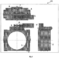
- FIG. 1 illustrates the assembly of the X-link tuning device ( 100 ).
- the said tuning device of the present invention comprises of a pair of square frames or flanges ( 1 ), which is used to attach the said tuning device ( 100 ) with the helium vessel ( 102 ) on both sides of the bellow on the SCRF cavity helium vessel.
- the each square flange ( 1 ) is made in two parts and these parts are assembled using dwell pins and bolts having spring locks or suitable fasteners, the assemblies of square flanges ( 1 ) are connected to each other through a pair of parallel sets of X-link levers and bearings ( 2 ) which are pivoted substantially at the middle portions.
- the top end of X-link ( 2 ) connects one square flange to the bottom end of the other square flange and vice-versa using thin flexure plates ( 3 ).
- the flexure plates ( 3 ) bend about its neutral position thereby allowing symmetric compression-expansion or expansion-compression cycle.
- the flexure plates ( 3 ) are joined on X-link ( 2 ) and square flange ( 1 ) by bolts having spring locks, secured by Dwell Pins ( 4 ).
- the square flanges ( 1 ) have a platform on the top that transfers the linear motion to the rest of the tuning device ( 100 ) and these are connected together by way of a ball screw mechanism as depicted in Fig-7.
- the ball type power screw mechanism is a main component of the linear actuation mechanism ( 7 ).
- the ball screw also referred to as power screw
- the ball screw is rotated using a worm wheel ( 9 ) having a suitable reduction gear ratio by its worm gear ( 11 ). In an exemplary embodiment a gear ratio of 1:30 is used.
- worm gear ( 11 ) is supported on the top of one of the square frame and worm gear's shaft (16) is extended to connect to a cryo-compatible compact gear unit having large gear reduction ratio which is connected through a shaft coupling (19) as shown in Fig-7.
- a cryo-compatible stepper motor ( 5 ) drives the said compact gear unit with range of 100 steps to 1000 or even more micro-steps in each motor rotation.
- the stepper motor shaft is extended on other side of the gear unit and suitable shaft coupling is made in order to have provision for coupling motor from outside the cryomodule assembly in case of motor failure during accelerator operation.
- the stepper motor ( 5 ) is used for tuning operations and is supported on the platform atop the square flanges ( 1 ) by way of a motor support ( 6 ) as depicted in Fig. 1 .
- a pair of piezo actuators ( 8 ) is used for fast tuning operations.
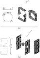
- the Figure 2 illustrates the three dimensional assembly of the tuning mechanism assembly (depicted as Fig 2 (a) ) and an exploded view (depicted as Fig. 2(b) ) of the power screw assembly.
- the power screw assembly comprises of a power screw ( 12 ) and piezo clasping plate ( 13 ) (detail illustration in figure 7 ), a ball screw mechanism (detailed cross sectional profile view in figure 7 (c) ), piezo support flange ( 82 ) and piezo support guide ( 81 ) (detailed illustration in figure 8 ), a pair of piezo actuators ( 8 ) (detailed illustration in figure 8 ), a worm wheel ( 9 ) connected to the ball screw mechanism as shown in Fig-7(c).
- the worm ( 11 ) is coupled to the worm wheel ( 9 ) for rotating the said wheel ( 9 ), the said worm ( 11 ) connected to a compact gear unit by way of a shaft ( 19 ) coupling, a stepper motor (
- the power screw ( 12 ) assembly is used for linear actuation and connects the square flanges ( 1 ).
- the square flanges ( 1 ) are substantially thick such that its bending due to compression or expansion of the tuning device ( 100 ) is negligible.
- the Figure 3 illustrates by way of a schematic diagram the representation of the motion transfer to the rest of tuning mechanism through the stepper motor ( 5 ).
- the said stepper motor ( 5 ) is adapted to rotate ( R1 ) the compact gear unit in both clockwise and anti-clockwise direction as depicted in Fig-3.
- the gear unit is coupled to the aforesaid worm ( 11 ) by way of a shaft coupling ( 19 ).
- the rotation ( R1 ) of the compact gear unit causes the worm ( 11 ) also to rotate which in turn drives the worm wheel ( 9 ).
- the worm wheel ( 9 ) is coupled with the power screw ( 12 ) thereby causing the power screw ( 12 ) to rotate ( R2 ).
- the arrangement of the flexure plates ( 3 ) and X-links ( 2 ) therefore causes the linear movement from the top of the tuning mechanism to be transferred to the bottom thereby leading to top to bottom load transfer as depicted as R4.
- the aforesaid arrangement can cause the tuning device to either expand or contract depending on whether the stepper motor ( 5 ) rotates in a clockwise or anticlockwise direction.
- FIG. 4 illustrates by way of a schematic diagram the representation of the motion transfer to the rest of tuning mechanism through the piezo actuator ( 8 ).
- This mechanism can be essentially divided into four steps. Firstly piezo actuation ( F1 ) results in exerting a force on the power screw ( 12 ) and piezo clasping plate ( 13 ). This leads to creating a linear drive motion ( F2 ) through the power screw ( 12 ) and the aforesaid linear actuator mechanism. The transfer of the linear motion ( F2 ) induces motion ( F3 ) in the square frame or flanges ( 1 ). Finally movement ( F4 ) of the flexural plates ( 3 ) and X-links ( 2 ) leads to transferring the load from top to bottom.
- Figure 5 illustrates the assembly of the square frame ( 1 ).
- the square frame ( 1 ) consists of two parts such that each part resembles a corner of a square shape and the said parts can be readily fit together. This is made in two parts to ensure plug compatibility i.e. to facilitate assembly of the tuner in already assembled cavity in cavity string.
- the assembled square frame has a circular cavity in between and a platform on top of the square flanges ( 1 ) for connecting the power screw ( 12 ).
- Figure 6 illustrates the assembly of X-link lever and bearing ( 2 ) mechanism, and an exploded view thereof.
- the said X-link mechanism consists of two levers ( L1, L2 ) arranged in a crossed position which are connected in the middle by way of a bearing ( B1 ).
- the aforesaid square flanges ( 1 ) are connected to each other through two parallel sets of X-link levers ( L1, L2 ) which are pivoted in between; wherein the top end of X-link connects one square flange to the bottom end of the other square flange and vice-versa using thin flexure plates ( 3 ); wherein the flexure plates ( 3 ) are joined on X-link and square flange by bolts having spring locks.
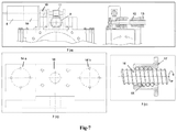
- FIG 7 illustrates the driving mechanism assembly and part details.
- the assembly of the driving mechanism comprises of a stepper motor ( 5 ), a compact gear box ( 10 ), a worm ( 11 ) coupled with a worm wheel ( 9 ), a ball screw mechanism and a power screw ( 12 ) and piezo clasping plate (13) as shown in Fig-7(a).
- the detailed top view and front view of an exemplary embodiment of the said clasping plate ( 13 ) can be found in figure 7(a) .
- the clasping plate ( 13 ) has provisions for attaching the power screw and the aforesaid piezo support flange ( 81 ) as shown in Fig-7(b).
- the attachment (15) for holding clasping plate with power screw with bolts is depicted in Fig-7(b).
- the piezo holding mechanism with bolts ( 14a, 14b ) also is shown in more details in Fig-7 (b).
- An exemplary embodiment of the ball screw mechanism is also depicted in figure 7 (c) .
- the said ball screw mechanism is adapted for minimizing friction caused due to movement of the power screw shaft ( 16 ) by use of steel balls ( 18 ).
- the steels balls ( 18 ) are adapted in between nut ( 17 ) and power shaft ( 16 ) for minimizing friction as depicted in Fig-7(c).
- This arrangement leads to low hysteresis due to rigid structure mechanism, use of ball type power screw (low stick-slip motion) has made the system with low friction and there is no friction in all the joints made by flexure plates joints (no stick slip motion).
- FIG. 8 illustrates the tuning piezo actuator ( 8 ) assembly and part details as per the scheme of tuning cycle.
- Fig-8(a) is for compression-expansion tuning cycle arrangement and fig-8(b) is for expansion-compression tuning cycle arrangement.
- the said actuator assembly comprising of a piezo stack or fast tuning element ( 84 ), two piezo support flanges ( 82, 85 ), piezo support guides ( 81 , 89 ), encapsulation tube ( 83 ), steel balls ( 86 ), grub screw ( 87 ) and fasteners ( 88 ) for assembly.
- Detailed front view and top view of the piezo support flange and piezo support guide are also given in figure 8 .
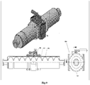
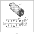
- Figure 9 illustrates one of the embodiments of the present invention where the X-link tuning device ( 100 ) is used as co-axial tuner.
- Figure 9 shows the different views of the X-link tuner device ( 100 ) mounted on the Helium vessel ( 102 ) as coaxial tuner.
- the side, top and isometric view of the X-link tuner device mounted on the helium vessel ( 102 ) is shown.
- the exemplary embodiment of mounted tuner device ( 100 ) as coaxial tuner in circular helium vessel ( 102 ) comprising SCRF cavity ( 101 ) is depicted herein.
- Figure 10 illustrates the yet another embodiment of the present invention where the X-link tuning device ( 100 ) is used as end tuner.
- Figure 10 shows the different views of the X-link tuner device ( 100 ) mounted on the Helium vessel ( 102 ) as end tuner.
- the side, top and isometric view of the X-link tuner device ( 100 ) mounted on the helium vessel ( 102 ) is shown.
- the exemplary embodiment of mounted tuner device ( 100 ) as end tuner in circular helium vessel ( 102 ) comprising SCRF cavity ( 101 ) is depicted herein.
- the description of the preferred embodiment of the present invention is applicable for entire range of single-cell or multi-cell axi-symmetric shapes of RF cavities such as pillbox, elliptical, re-entrant, low-loss, spherical or suitably shaped RF accelerating structures etc.
- the person skilled in art can adapt the present tuner device to be suitably also apply the same for other shapes of RF cavity.
- Design adaptability with changes in RF cavity shape can be worked out easily and the only pivotal position of the lever ( L1, L2 ) needs to be adjusted accordingly and hence the design of the square frame ( 1 ), drive mechanism, piezo mechanism and flexure system remains the same for all shapes for a particular RF cavity frequency.
- the mechanism of the tuner device ( 100 ) of the present invention is scalable for around 300 MHz to 1500 MHz range of RF frequency of an accelerator cavity.
- the use of cryo-compatible stainless steel, SS316LN, or similar material in the aforesaid mechanism is not only cost effective but also gives freedom to use off-the-shelf accessories/ components (e.g. ball screws arrangement, coupling, worm of the worm wheel, fasteners etc.).
- the piezo actuator ( 8 ) setup is used to transfer the force required for fast and fine control of frequency for tuning.
- the aforesaid mechanism uses a ball screw assembly, in an exemplary implementation the pitch may be 4 mm or higher for partial rotation wherein partial rotation is defined as less then quarter rotation of the power screw for negligible backlash from driving mechanism with low frictional resistance.
- the person skilled in art may implement the same idea with different specification of the assembly like pitch and rotations and those are well obvious to a person skilled in art and should be understood to be well within the scope of the present invention.
- the above mechanism when used for slow tuning improves tuning capabilities to more than 1.5 mm at the cavity level with permissible strains in the flexure plates ( 3 ).
- the mechanism is adapted to provide flexibility to be operated in expansion as well as in compression.
- This mechanism can be used in compression-expansion cycle for tuning or it can be used in expansion-compression cycle as per the requirement of the RF cavity tuning i.e. if the SCRF cavity after cool-down to cryogenic temperature (2K or 4.2K) has a lower frequency than the targeted frequency, the mechanism can be used as expansion-compression or vice-versa.
- the aforesaid mechanism can be advantageously designed as a co-axial tuning system or as an end tuning system as per the suitability of the superconducting RF cavity ( 101 ) space in the cryomodule.
- One design of a co-axial tuning system for an RF cavity diameter is applicable on other RF cavity having the double diameter RF cavity (i.e. half frequency of the RF cavity) as an end tuning system as shown in Fig-10.
- the mechanism components in their preferred embodiments are simple and easy in manufacturing. No welding is involved hence no distortions occur in the present mechanism and the joints are bolted and locked hence providing ease in assembly of the system.
- the joints of flexure plates, square flanges and X link levers are made with dwell pin and secured by suitable fasteners.
- the driving system of the present invention is straightforward, compact and easily demountable.
- the driving mechanism of the present invention can be modified either as parallel to the cavity axis or as perpendicular to the cavity axis.
- the worth of this tuning system lies in finding innovative way out to biggest challenges in SC cavity tuners like cost and direct load transfer from the tuner frame to the helium vessel of the RF cavity.
- the less number of components and rigid frame enhances the efficiency of motion transfer.
- the X-link tuner made in non-magnetic SS316LN not only gives strength to the system but also makes the manufacturing simple and economic.
- the X-link tuner device of the present invention can be operated in compression mode without losing symmetry of movement with slow and fast tuning options from a single point or no load point.
- the present tuner device provides wider tuning range with low hysteresis is another salient feature of this mechanism e.g. tuning range of +/- 1.5mm with low hysteresis for 1300 MHz 9-cell cavity and/or 650MHz 5-cell cavity is achieved.
- the components of tuning device also can be dry-lubricated using WS 2 (Tungsten disulfide) or a suitable dry lubricant, which not only reduces the friction but also reduces wear, seizing and galling of components.
- WS 2 Tin disulfide
- suitable dry lubricant which not only reduces the friction but also reduces wear, seizing and galling of components.
- the design of the tuning device for SCRF cavities where the X-link tuner can perform both slow and fast tunings options simultaneously with low hysteresis is also possible.
- the use of SS316LN or any non-magnetic steel makes the tuner rigid, economic and easy for fabrication.
- Tuners in the SCRF cavities are one of the cost driving factors and as SCRF accelerator projects around the world are current technology for almost all high energy physics program, a reduction in cost of tuner will have a major effect on such project.
- the invention will also be helpful to reduce the overall cost of the development of superconducting proton linac using SCRF cavities.
Landscapes
- Physics & Mathematics (AREA)
- Engineering & Computer Science (AREA)
- Plasma & Fusion (AREA)
- Spectroscopy & Molecular Physics (AREA)
- Particle Accelerators (AREA)
- Control Of Motors That Do Not Use Commutators (AREA)
Claims (16)
- Zerlegbare Abstimmeinheit (100) für einen supraleitenden Radiofrequenz-Resonator (SCRF), die Folgendes umfasst:mindestens zwei Vierkantflansche (1);mindestens zwei Querverbindungshebelsätze (2);mindestens vier am oberen Ende der Querverbindungshebel angebrachte dünne, flache Biegeplatten (3) und mindestens vier der genannten Platten (3), die am unteren Ende der Querverbindungshebel angebracht sind;einen oder mehrere Piezoaktuatorbaugruppen (8);mindestens eine Motorbaugruppe;mindestens eine Powerschraubenbaugruppe;wobei die genannten Querverbindungshebelsätze (2) so ausgelegt sind, dass sie im Wesentlichen an ihrem mittleren Abschnitt ihren Angelpunkt aufweisen;
und die Baugruppen von Motor, Piezoaktuator (8) und Powerschraube so ausgelegt sind, dass sie die Bewegung des oberen und unteren Endes der genannten Vierkantflansche (1) ausgleichen;
wobei die genannten Vierkantflansche (1) miteinander über die genannten Querverbindungshebelsätze (2) verbunden sind; und die genannten dünnen, flachen Biegeplatten (3) das obere Ende der genannten Querverbindungshebel (2) mit mindestens einem Vierkantflansch und das untere Ende der genannten Querverbindungshebel mit mindestens dem anderen Vierkantflansch verbinden
und umgekehrt, so dass eine lineare Bewegung von der Oberseite der genannten Abstimmeinheit nach unten übertragen werden kann, die zu einer Lastübertragung von oben nach unten führt; wodurch eine langsame und/oder schnelle Abstimmungseinstellung zum Übertragen der zur feinen sowie schnellen Steuerung der Frequenz des SCRF-Resonators erforderlichen Kraft erzielt wird. - Abstimmeinheit nach Anspruch 1, wobei die genannten Biegeplatten so konfiguriert sind, dass sie die genannten Querverbindungshebel mit dem genannten Vierkantflansch mittels Spannstiften (4) in Verbindung mit geeigneten Befestigungselementen verbinden.
- Abstimmeinheit nach Anspruch 1, wobei die genannten Querverbindungshebelsätze im Wesentlichen parallel zueinander sind.
- Abstimmeinheit nach Anspruch 1, wobei die genannten Vierkantflansche eine so große Stärke aufweisen, dass ihre Biegung aufgrund von Kompression oder Ausdehnung unerheblich ist.
- Abstimmeinheit nach Anspruch 1, wobei die genannte Piezoaktuatorbaugruppe (8) Folgendes umfasst:- mindestens eine Spannplatte (13);- mindestens zwei Stützflansche (82, 85);- mindestens zwei Stützführungen (81, 89); und- mindestens einen Piezostapel oder ein schnelles Abstimmelement (84);wobei der genannte Aktuator darauf konfiguriert ist, eine Kraft auf die Powerschraubenbaugruppe auszuüben und die Spannplatte darauf ausgelegt ist, eine lineare Antriebsbewegung über die genannte Powerschraubenbaugruppe zu erzeugen.
- Abstimmeinheit nach Anspruch 1, wobei die genannte Powerschraubenbaugruppe Folgendes umfasst:- eine Powerschraube (12);- einen Kugelumlaufspindelmechanismus (7), umfassendwobei der genannte Kugelumlaufspindelmechanismus außerdem eine Vielzahl an Kugeln aus rostfreiem Stahl (18), eine Mutter (17) und die genannte Powerschraube (12) umfasst;- ein Schneckenrad (9); und- ein Schneckengetriebe (11)mit einer Welle (16), wobei das genannte Schneckenrad darauf ausgelegt ist, von der Welle (16) des Schneckengetriebes angetrieben zu werden;
und wobei die genannte Powerschraube unter Einsatz des genannten Schneckenrads bei einem Untersetzungsverhältnis von 1:30 oder einem jeweils geeigneten Untersetzungsverhältnis von der genannten Schnecke zur linearen Bewegung gedreht wird. - Abstimmeinheit nach Anspruch 1, die außerdem ein kryo-kompatibles kompaktes Getriebe mit einem hohen Untersetzungsverhältnis umfasst, das von der genannten Motorbaugruppe sowohl im als auch gegen den Uhrzeigersinn für eine feine Auflösung in einem Bereich von ca. 100 bis 1000 Schritten bei jeder Motordrehung angetrieben wird.
- Abstimmeinheit nach Anspruch 1, wobei die genannte Motorbaugruppe einen Schrittmotor (5) oder einen Gleichstrommotor mit verlängerter Welle umfasst, die darauf ausgelegt ist, den Motor extern anzukuppeln, um die Fehlersuche im Fall eines Motorfehlers zu erleichtern.
- Abstimmeinheit nach Anspruch 1, wobei die genannten Biegeplatten, Vierkantflansche und Querverbindungshebel Verbindungen über Spannstifte aufweisen, die von geeigneten Befestigungselementen gesichert werden.
- Abstimmeinheit nach Anspruch 1, wobei die genannte Einheit in einem Radiofrequenzbereich von ca. 300 MHz bis 1500 MHz eines Beschleuniger-Resonators skaliert werden kann.
- Abstimmeinheit nach Anspruch 1, wobei ein Abstimmbereich von ca. +/- 1,5 mm innerhalb einer elastischen Grenze mit niedriger Hysterese für Resonatoren mit 9 Zellen und ca. 1300 MHz und/oder Resonatoren mit 5 Zellen und 650 MHz erzielt werden kann.
- Abstimmeinheit nach Anspruch 1, wobei die genannte Abstimmeinheit darauf ausgelegt ist, als koaxiales Abstimmsystem und/oder Endabstimmungssystem eingesetzt zu werden, das wegen der Eignung des supraleitenden RF-Resonators im Kryomodul an beiden Enden des Dehngefäßes eines Heliumbehälters angebracht wird.
- Abstimmeinheit nach Anspruch 1, wobei die genannte Abstimmeinheit angepasst wird, um in einer ganzen Reihe von ein- oder mehrzelligen axisymmetrischen Formen von RF-Resonatoren wie Pillboxen, elliptischen, re-entranten, verlustarmen, sphärischen oder geeignet geformten RF-Beschleunigungsstrukturen eingesetzt zu werden.
- Abstimmeinheit nach Anspruch 1, wobei die genannte schnelle Abstimmungseinstellung oben auf den genannten Vierkantflanschen darauf ausgelegt ist, sowohl langsame als auch schnelle Abstimmungseinstellungen mit niedriger Hysterese von der genannten Plattform aus zu vereinfachen und die Gesamtabmessungen des Systems zu verringern.
- Abstimmeinheit nach Anspruch 1, wobei die genannte Abstimmvorrichtung in einem Kompressions-/Ausdehnungszyklus zum Abstimmen oder in Ausdehnungs-/Kompressionszyklen entsprechend den Anforderungen der Abstimmung des RF-Resonators eingesetzt werden kann.
- Abstimmeinheit nach Anspruch 1, wobei die Schwenkposition der genannten Querverbindungshebel änderbar ausgelegt ist, um die Abstimmeinheit an die Änderung der RF-Resonatorform anzupassen.
Applications Claiming Priority (1)
| Application Number | Priority Date | Filing Date | Title |
|---|---|---|---|
| PCT/IB2015/051517 WO2016139504A1 (en) | 2015-03-02 | 2015-03-02 | Device for tuning scrf cavity |
Publications (2)
| Publication Number | Publication Date |
|---|---|
| EP3266285A1 EP3266285A1 (de) | 2018-01-10 |
| EP3266285B1 true EP3266285B1 (de) | 2018-05-16 |
Family
ID=52780555
Family Applications (1)
| Application Number | Title | Priority Date | Filing Date |
|---|---|---|---|
| EP15712694.7A Not-in-force EP3266285B1 (de) | 2015-03-02 | 2015-03-02 | Vorrichtung zur einstellung eines scrf-resonators |
Country Status (4)
| Country | Link |
|---|---|
| US (1) | US10524346B2 (de) |
| EP (1) | EP3266285B1 (de) |
| JP (1) | JP6259913B2 (de) |
| WO (1) | WO2016139504A1 (de) |
Cited By (1)
| Publication number | Priority date | Publication date | Assignee | Title |
|---|---|---|---|---|
| CN109219227A (zh) * | 2018-11-01 | 2019-01-15 | 中国科学院近代物理研究所 | 调谐装置及具有其的超导加速腔 |
Families Citing this family (13)
| Publication number | Priority date | Publication date | Assignee | Title |
|---|---|---|---|---|
| GB201420936D0 (en) * | 2014-11-25 | 2015-01-07 | Isis Innovation | Radio frequency cavities |
| US10485090B2 (en) | 2016-01-22 | 2019-11-19 | Jefferson Science Associates, Llc | High performance SRF accelerator structure and method |
| JP6800607B2 (ja) * | 2016-05-06 | 2020-12-16 | 三菱重工機械システム株式会社 | 加速空洞、加速器及び加速空洞の共振周波数調整方法 |
| JP7201667B2 (ja) * | 2017-08-28 | 2023-01-10 | ミューオンズ インコーポレイテッド | 内部変調機能付きマグネトロンrf源を使用したパルス電力生成 |
| US20190139006A1 (en) * | 2017-11-03 | 2019-05-09 | John Tyler PIAZZA | Charitable gifting system and method of use |
| CN107896416A (zh) * | 2017-12-13 | 2018-04-10 | 合肥中科离子医学技术装备有限公司 | 一种超导回旋加速器谐振腔微扰棒驱动机构及其工作方式 |
| CN108449860A (zh) * | 2018-03-05 | 2018-08-24 | 中国科学院高能物理研究所 | 一种低温插杆调谐器及超导腔 |
| US10485088B1 (en) * | 2018-09-25 | 2019-11-19 | Fermi Research Alliance, Llc | Radio frequency tuning of dressed multicell cavities using pressurized balloons |
| US10645793B2 (en) * | 2018-09-25 | 2020-05-05 | Fermi Research Alliance, Llc | Automatic tuning of dressed multicell cavities using pressurized balloons |
| CN110067832B (zh) * | 2019-05-05 | 2022-04-19 | 广东工业大学 | 一种压电陶瓷驱动器预紧装置 |
| JP7550702B2 (ja) | 2021-04-06 | 2024-09-13 | 三菱電機株式会社 | 加速空洞 |
| EP4690452A1 (de) * | 2023-04-04 | 2026-02-11 | Centre National de la Recherche Scientifique | Stick-slip positionierer |
| CN119155879B (zh) * | 2024-09-11 | 2025-09-16 | 电子科技大学 | 调谐装置以及超导加速器 |
Family Cites Families (1)
| Publication number | Priority date | Publication date | Assignee | Title |
|---|---|---|---|---|
| US6657515B2 (en) | 2001-06-18 | 2003-12-02 | Energen, Llp | Tuning mechanism for a superconducting radio frequency particle accelerator cavity |
-
2015
- 2015-03-02 EP EP15712694.7A patent/EP3266285B1/de not_active Not-in-force
- 2015-03-02 JP JP2016528072A patent/JP6259913B2/ja not_active Expired - Fee Related
- 2015-03-02 WO PCT/IB2015/051517 patent/WO2016139504A1/en not_active Ceased
- 2015-03-02 US US15/022,358 patent/US10524346B2/en not_active Expired - Fee Related
Non-Patent Citations (1)
| Title |
|---|
| None * |
Cited By (2)
| Publication number | Priority date | Publication date | Assignee | Title |
|---|---|---|---|---|
| CN109219227A (zh) * | 2018-11-01 | 2019-01-15 | 中国科学院近代物理研究所 | 调谐装置及具有其的超导加速腔 |
| CN109219227B (zh) * | 2018-11-01 | 2021-07-27 | 中国科学院近代物理研究所 | 调谐装置及具有其的超导加速腔 |
Also Published As
| Publication number | Publication date |
|---|---|
| US10524346B2 (en) | 2019-12-31 |
| US20170006695A1 (en) | 2017-01-05 |
| JP2017517090A (ja) | 2017-06-22 |
| WO2016139504A1 (en) | 2016-09-09 |
| JP6259913B2 (ja) | 2018-01-10 |
| EP3266285A1 (de) | 2018-01-10 |
Similar Documents
| Publication | Publication Date | Title |
|---|---|---|
| US10524346B2 (en) | Device for tuning SCRF cavity | |
| Cai et al. | Modeling and controller design of a 6-DOF precision positioning system | |
| US10384341B2 (en) | Redundant parallel positioning table device | |
| US6411187B1 (en) | Adjustable hybrid magnetic apparatus | |
| Jia et al. | Theoretical modeling and experimental investigation on a novel screwed-type piezoelectric focusing mechanism for space cameras | |
| CN110081080A (zh) | 三自由度解耦超精密大行程定位及激振装置 | |
| JP2021022477A (ja) | アンジュレータ装置 | |
| DE102014001526B4 (de) | Supraleiter-Lagermittel und Vorrichtung zur Materialuntersuchung und/oder Materialbearbeitung | |
| Artoos et al. | Development of SRF cavity tuners for CERN | |
| CN212230084U (zh) | 基于压电驱动的托卡马克装置轨道检测系统 | |
| Wang et al. | A review of module adjustment for space on-orbit assembled antenna | |
| Kostin et al. | A tuner for a superconducting traveling wave cavity prototype | |
| CN115465478B (zh) | 补偿型航天器分离装置 | |
| JP5066039B2 (ja) | パラレルリンク機構およびパラレルリンク機構を備えた真空成膜装置 | |
| Hu et al. | Applications and development of micro-or nano-metric multi degree of freedom adjusting displacement scaling mechanisms for primary mirror | |
| CN108879105B (zh) | 紧缩场拼合反射面板支撑调节的冗余并联装置及调节方法 | |
| Zhang et al. | Complementary Clamp-Based Multi-Degree-of-Freedom Parallel Inchworm Actuator | |
| Tang et al. | Optimal design, modeling and analysis of a 2-DOF nanopositioning stage with dual-mode: Towards high-rate AFM scanning | |
| JP2023088425A (ja) | 共振周波数調整装置 | |
| Wang et al. | Design and control of a decoupled micro-positioning stage using corrugated flexure units | |
| Paparella | Overview of recent tuner development on elliptical and low-beta cavities | |
| CN111193434B (zh) | 基于夹心式框架作动器的轨道运载系统及其工作方法 | |
| 吴石磊 et al. | Structure design method of complaint parallel mechanism for grating tiling with heavy load capacity and high precision | |
| Sun et al. | Development of a flexure-based XY positioning stage for micro/nano manipulation | |
| Zhang et al. | Design and modeling of a novel 3-DOF large-travel parallel micro/nano-positioning stage |
Legal Events
| Date | Code | Title | Description |
|---|---|---|---|
| STAA | Information on the status of an ep patent application or granted ep patent |
Free format text: STATUS: THE INTERNATIONAL PUBLICATION HAS BEEN MADE |
|
| PUAI | Public reference made under article 153(3) epc to a published international application that has entered the european phase |
Free format text: ORIGINAL CODE: 0009012 |
|
| STAA | Information on the status of an ep patent application or granted ep patent |
Free format text: STATUS: REQUEST FOR EXAMINATION WAS MADE |
|
| 17P | Request for examination filed |
Effective date: 20160505 |
|
| AK | Designated contracting states |
Kind code of ref document: A1 Designated state(s): AL AT BE BG CH CY CZ DE DK EE ES FI FR GB GR HR HU IE IS IT LI LT LU LV MC MK MT NL NO PL PT RO RS SE SI SK SM TR |
|
| AX | Request for extension of the european patent |
Extension state: BA ME |
|
| GRAP | Despatch of communication of intention to grant a patent |
Free format text: ORIGINAL CODE: EPIDOSNIGR1 |
|
| STAA | Information on the status of an ep patent application or granted ep patent |
Free format text: STATUS: GRANT OF PATENT IS INTENDED |
|
| DAV | Request for validation of the european patent (deleted) | ||
| DAX | Request for extension of the european patent (deleted) | ||
| INTG | Intention to grant announced |
Effective date: 20180208 |
|
| GRAS | Grant fee paid |
Free format text: ORIGINAL CODE: EPIDOSNIGR3 |
|
| GRAA | (expected) grant |
Free format text: ORIGINAL CODE: 0009210 |
|
| STAA | Information on the status of an ep patent application or granted ep patent |
Free format text: STATUS: THE PATENT HAS BEEN GRANTED |
|
| AK | Designated contracting states |
Kind code of ref document: B1 Designated state(s): AL AT BE BG CH CY CZ DE DK EE ES FI FR GB GR HR HU IE IS IT LI LT LU LV MC MK MT NL NO PL PT RO RS SE SI SK SM TR |
|
| REG | Reference to a national code |
Ref country code: GB Ref legal event code: FG4D |
|
| REG | Reference to a national code |
Ref country code: CH Ref legal event code: EP |
|
| REG | Reference to a national code |
Ref country code: IE Ref legal event code: FG4D |
|
| REG | Reference to a national code |
Ref country code: DE Ref legal event code: R096 Ref document number: 602015011170 Country of ref document: DE |
|
| REG | Reference to a national code |
Ref country code: CH Ref legal event code: NV Representative=s name: RAPISARDI INTELLECTUAL PROPERTY SA, CH Ref country code: AT Ref legal event code: REF Ref document number: 1000716 Country of ref document: AT Kind code of ref document: T Effective date: 20180615 |
|
| REG | Reference to a national code |
Ref country code: NL Ref legal event code: MP Effective date: 20180516 |
|
| REG | Reference to a national code |
Ref country code: LT Ref legal event code: MG4D |
|
| PG25 | Lapsed in a contracting state [announced via postgrant information from national office to epo] |
Ref country code: BG Free format text: LAPSE BECAUSE OF FAILURE TO SUBMIT A TRANSLATION OF THE DESCRIPTION OR TO PAY THE FEE WITHIN THE PRESCRIBED TIME-LIMIT Effective date: 20180816 Ref country code: NO Free format text: LAPSE BECAUSE OF FAILURE TO SUBMIT A TRANSLATION OF THE DESCRIPTION OR TO PAY THE FEE WITHIN THE PRESCRIBED TIME-LIMIT Effective date: 20180816 Ref country code: FI Free format text: LAPSE BECAUSE OF FAILURE TO SUBMIT A TRANSLATION OF THE DESCRIPTION OR TO PAY THE FEE WITHIN THE PRESCRIBED TIME-LIMIT Effective date: 20180516 Ref country code: SE Free format text: LAPSE BECAUSE OF FAILURE TO SUBMIT A TRANSLATION OF THE DESCRIPTION OR TO PAY THE FEE WITHIN THE PRESCRIBED TIME-LIMIT Effective date: 20180516 Ref country code: ES Free format text: LAPSE BECAUSE OF FAILURE TO SUBMIT A TRANSLATION OF THE DESCRIPTION OR TO PAY THE FEE WITHIN THE PRESCRIBED TIME-LIMIT Effective date: 20180516 Ref country code: LT Free format text: LAPSE BECAUSE OF FAILURE TO SUBMIT A TRANSLATION OF THE DESCRIPTION OR TO PAY THE FEE WITHIN THE PRESCRIBED TIME-LIMIT Effective date: 20180516 |
|
| PG25 | Lapsed in a contracting state [announced via postgrant information from national office to epo] |
Ref country code: NL Free format text: LAPSE BECAUSE OF FAILURE TO SUBMIT A TRANSLATION OF THE DESCRIPTION OR TO PAY THE FEE WITHIN THE PRESCRIBED TIME-LIMIT Effective date: 20180516 Ref country code: LV Free format text: LAPSE BECAUSE OF FAILURE TO SUBMIT A TRANSLATION OF THE DESCRIPTION OR TO PAY THE FEE WITHIN THE PRESCRIBED TIME-LIMIT Effective date: 20180516 Ref country code: RS Free format text: LAPSE BECAUSE OF FAILURE TO SUBMIT A TRANSLATION OF THE DESCRIPTION OR TO PAY THE FEE WITHIN THE PRESCRIBED TIME-LIMIT Effective date: 20180516 Ref country code: GR Free format text: LAPSE BECAUSE OF FAILURE TO SUBMIT A TRANSLATION OF THE DESCRIPTION OR TO PAY THE FEE WITHIN THE PRESCRIBED TIME-LIMIT Effective date: 20180817 Ref country code: HR Free format text: LAPSE BECAUSE OF FAILURE TO SUBMIT A TRANSLATION OF THE DESCRIPTION OR TO PAY THE FEE WITHIN THE PRESCRIBED TIME-LIMIT Effective date: 20180516 |
|
| REG | Reference to a national code |
Ref country code: AT Ref legal event code: MK05 Ref document number: 1000716 Country of ref document: AT Kind code of ref document: T Effective date: 20180516 |
|
| PG25 | Lapsed in a contracting state [announced via postgrant information from national office to epo] |
Ref country code: EE Free format text: LAPSE BECAUSE OF FAILURE TO SUBMIT A TRANSLATION OF THE DESCRIPTION OR TO PAY THE FEE WITHIN THE PRESCRIBED TIME-LIMIT Effective date: 20180516 Ref country code: PL Free format text: LAPSE BECAUSE OF FAILURE TO SUBMIT A TRANSLATION OF THE DESCRIPTION OR TO PAY THE FEE WITHIN THE PRESCRIBED TIME-LIMIT Effective date: 20180516 Ref country code: RO Free format text: LAPSE BECAUSE OF FAILURE TO SUBMIT A TRANSLATION OF THE DESCRIPTION OR TO PAY THE FEE WITHIN THE PRESCRIBED TIME-LIMIT Effective date: 20180516 Ref country code: CZ Free format text: LAPSE BECAUSE OF FAILURE TO SUBMIT A TRANSLATION OF THE DESCRIPTION OR TO PAY THE FEE WITHIN THE PRESCRIBED TIME-LIMIT Effective date: 20180516 Ref country code: AT Free format text: LAPSE BECAUSE OF FAILURE TO SUBMIT A TRANSLATION OF THE DESCRIPTION OR TO PAY THE FEE WITHIN THE PRESCRIBED TIME-LIMIT Effective date: 20180516 Ref country code: SK Free format text: LAPSE BECAUSE OF FAILURE TO SUBMIT A TRANSLATION OF THE DESCRIPTION OR TO PAY THE FEE WITHIN THE PRESCRIBED TIME-LIMIT Effective date: 20180516 Ref country code: DK Free format text: LAPSE BECAUSE OF FAILURE TO SUBMIT A TRANSLATION OF THE DESCRIPTION OR TO PAY THE FEE WITHIN THE PRESCRIBED TIME-LIMIT Effective date: 20180516 |
|
| REG | Reference to a national code |
Ref country code: DE Ref legal event code: R097 Ref document number: 602015011170 Country of ref document: DE |
|
| PG25 | Lapsed in a contracting state [announced via postgrant information from national office to epo] |
Ref country code: SM Free format text: LAPSE BECAUSE OF FAILURE TO SUBMIT A TRANSLATION OF THE DESCRIPTION OR TO PAY THE FEE WITHIN THE PRESCRIBED TIME-LIMIT Effective date: 20180516 Ref country code: IT Free format text: LAPSE BECAUSE OF FAILURE TO SUBMIT A TRANSLATION OF THE DESCRIPTION OR TO PAY THE FEE WITHIN THE PRESCRIBED TIME-LIMIT Effective date: 20180516 |
|
| PLBE | No opposition filed within time limit |
Free format text: ORIGINAL CODE: 0009261 |
|
| STAA | Information on the status of an ep patent application or granted ep patent |
Free format text: STATUS: NO OPPOSITION FILED WITHIN TIME LIMIT |
|
| 26N | No opposition filed |
Effective date: 20190219 |
|
| PGFP | Annual fee paid to national office [announced via postgrant information from national office to epo] |
Ref country code: CH Payment date: 20190228 Year of fee payment: 5 Ref country code: FR Payment date: 20190328 Year of fee payment: 5 |
|
| PGFP | Annual fee paid to national office [announced via postgrant information from national office to epo] |
Ref country code: DE Payment date: 20190528 Year of fee payment: 5 |
|
| PG25 | Lapsed in a contracting state [announced via postgrant information from national office to epo] |
Ref country code: MC Free format text: LAPSE BECAUSE OF FAILURE TO SUBMIT A TRANSLATION OF THE DESCRIPTION OR TO PAY THE FEE WITHIN THE PRESCRIBED TIME-LIMIT Effective date: 20180516 |
|
| GBPC | Gb: european patent ceased through non-payment of renewal fee |
Effective date: 20190302 |
|
| PG25 | Lapsed in a contracting state [announced via postgrant information from national office to epo] |
Ref country code: AL Free format text: LAPSE BECAUSE OF FAILURE TO SUBMIT A TRANSLATION OF THE DESCRIPTION OR TO PAY THE FEE WITHIN THE PRESCRIBED TIME-LIMIT Effective date: 20180516 Ref country code: LU Free format text: LAPSE BECAUSE OF NON-PAYMENT OF DUE FEES Effective date: 20190302 |
|
| REG | Reference to a national code |
Ref country code: BE Ref legal event code: MM Effective date: 20190331 |
|
| PG25 | Lapsed in a contracting state [announced via postgrant information from national office to epo] |
Ref country code: IE Free format text: LAPSE BECAUSE OF NON-PAYMENT OF DUE FEES Effective date: 20190302 Ref country code: GB Free format text: LAPSE BECAUSE OF NON-PAYMENT OF DUE FEES Effective date: 20190302 |
|
| PG25 | Lapsed in a contracting state [announced via postgrant information from national office to epo] |
Ref country code: BE Free format text: LAPSE BECAUSE OF NON-PAYMENT OF DUE FEES Effective date: 20190331 |
|
| PG25 | Lapsed in a contracting state [announced via postgrant information from national office to epo] |
Ref country code: TR Free format text: LAPSE BECAUSE OF FAILURE TO SUBMIT A TRANSLATION OF THE DESCRIPTION OR TO PAY THE FEE WITHIN THE PRESCRIBED TIME-LIMIT Effective date: 20180516 |
|
| PG25 | Lapsed in a contracting state [announced via postgrant information from national office to epo] |
Ref country code: MT Free format text: LAPSE BECAUSE OF NON-PAYMENT OF DUE FEES Effective date: 20190302 Ref country code: PT Free format text: LAPSE BECAUSE OF FAILURE TO SUBMIT A TRANSLATION OF THE DESCRIPTION OR TO PAY THE FEE WITHIN THE PRESCRIBED TIME-LIMIT Effective date: 20180917 |
|
| REG | Reference to a national code |
Ref country code: DE Ref legal event code: R119 Ref document number: 602015011170 Country of ref document: DE |
|
| REG | Reference to a national code |
Ref country code: CH Ref legal event code: PL |
|
| PG25 | Lapsed in a contracting state [announced via postgrant information from national office to epo] |
Ref country code: FR Free format text: LAPSE BECAUSE OF NON-PAYMENT OF DUE FEES Effective date: 20200331 Ref country code: CH Free format text: LAPSE BECAUSE OF NON-PAYMENT OF DUE FEES Effective date: 20200331 Ref country code: LI Free format text: LAPSE BECAUSE OF NON-PAYMENT OF DUE FEES Effective date: 20200331 Ref country code: DE Free format text: LAPSE BECAUSE OF NON-PAYMENT OF DUE FEES Effective date: 20201001 |
|
| PG25 | Lapsed in a contracting state [announced via postgrant information from national office to epo] |
Ref country code: CY Free format text: LAPSE BECAUSE OF FAILURE TO SUBMIT A TRANSLATION OF THE DESCRIPTION OR TO PAY THE FEE WITHIN THE PRESCRIBED TIME-LIMIT Effective date: 20180516 |
|
| PG25 | Lapsed in a contracting state [announced via postgrant information from national office to epo] |
Ref country code: IS Free format text: LAPSE BECAUSE OF FAILURE TO SUBMIT A TRANSLATION OF THE DESCRIPTION OR TO PAY THE FEE WITHIN THE PRESCRIBED TIME-LIMIT Effective date: 20180916 |
|
| PG25 | Lapsed in a contracting state [announced via postgrant information from national office to epo] |
Ref country code: HU Free format text: LAPSE BECAUSE OF FAILURE TO SUBMIT A TRANSLATION OF THE DESCRIPTION OR TO PAY THE FEE WITHIN THE PRESCRIBED TIME-LIMIT; INVALID AB INITIO Effective date: 20150302 |
|
| PG25 | Lapsed in a contracting state [announced via postgrant information from national office to epo] |
Ref country code: SI Free format text: LAPSE BECAUSE OF FAILURE TO SUBMIT A TRANSLATION OF THE DESCRIPTION OR TO PAY THE FEE WITHIN THE PRESCRIBED TIME-LIMIT Effective date: 20180516 |
|
| PG25 | Lapsed in a contracting state [announced via postgrant information from national office to epo] |
Ref country code: MK Free format text: LAPSE BECAUSE OF FAILURE TO SUBMIT A TRANSLATION OF THE DESCRIPTION OR TO PAY THE FEE WITHIN THE PRESCRIBED TIME-LIMIT Effective date: 20180516 |