EP3267158B1 - Ultraschallzähler zur erfassung einer durchflussmenge eines fluids - Google Patents
Ultraschallzähler zur erfassung einer durchflussmenge eines fluids Download PDFInfo
- Publication number
- EP3267158B1 EP3267158B1 EP17001055.7A EP17001055A EP3267158B1 EP 3267158 B1 EP3267158 B1 EP 3267158B1 EP 17001055 A EP17001055 A EP 17001055A EP 3267158 B1 EP3267158 B1 EP 3267158B1
- Authority
- EP
- European Patent Office
- Prior art keywords
- flow
- section
- circumferential
- side wall
- fluid
- Prior art date
- Legal status (The legal status is an assumption and is not a legal conclusion. Google has not performed a legal analysis and makes no representation as to the accuracy of the status listed.)
- Active
Links
Images


Classifications
-
- G—PHYSICS
- G01—MEASURING; TESTING
- G01F—MEASURING VOLUME, VOLUME FLOW, MASS FLOW OR LIQUID LEVEL; METERING BY VOLUME
- G01F1/00—Measuring the volume flow or mass flow of fluid or fluent solid material wherein the fluid passes through a meter in a continuous flow
- G01F1/66—Measuring the volume flow or mass flow of fluid or fluent solid material wherein the fluid passes through a meter in a continuous flow by measuring frequency, phase shift or propagation time of electromagnetic or other waves, e.g. using ultrasonic flowmeters
-
- G—PHYSICS
- G01—MEASURING; TESTING
- G01F—MEASURING VOLUME, VOLUME FLOW, MASS FLOW OR LIQUID LEVEL; METERING BY VOLUME
- G01F1/00—Measuring the volume flow or mass flow of fluid or fluent solid material wherein the fluid passes through a meter in a continuous flow
- G01F1/66—Measuring the volume flow or mass flow of fluid or fluent solid material wherein the fluid passes through a meter in a continuous flow by measuring frequency, phase shift or propagation time of electromagnetic or other waves, e.g. using ultrasonic flowmeters
- G01F1/662—Constructional details
-
- G—PHYSICS
- G01—MEASURING; TESTING
- G01F—MEASURING VOLUME, VOLUME FLOW, MASS FLOW OR LIQUID LEVEL; METERING BY VOLUME
- G01F15/00—Details of, or accessories for, apparatus of groups G01F1/00 - G01F13/00 insofar as such details or appliances are not adapted to particular types of such apparatus
- G01F15/02—Compensating or correcting for variations in pressure, density or temperature
- G01F15/028—Compensating or correcting for variations in pressure, density or temperature for low flow rates
-
- G—PHYSICS
- G01—MEASURING; TESTING
- G01F—MEASURING VOLUME, VOLUME FLOW, MASS FLOW OR LIQUID LEVEL; METERING BY VOLUME
- G01F25/00—Testing or calibration of apparatus for measuring volume, volume flow or liquid level or for metering by volume
- G01F25/10—Testing or calibration of apparatus for measuring volume, volume flow or liquid level or for metering by volume of flowmeters
-
- G—PHYSICS
- G01—MEASURING; TESTING
- G01F—MEASURING VOLUME, VOLUME FLOW, MASS FLOW OR LIQUID LEVEL; METERING BY VOLUME
- G01F1/00—Measuring the volume flow or mass flow of fluid or fluent solid material wherein the fluid passes through a meter in a continuous flow
- G01F1/76—Devices for measuring mass flow of a fluid or a fluent solid material
- G01F1/86—Indirect mass flowmeters, e.g. measuring volume flow and density, temperature or pressure
-
- G—PHYSICS
- G01—MEASURING; TESTING
- G01F—MEASURING VOLUME, VOLUME FLOW, MASS FLOW OR LIQUID LEVEL; METERING BY VOLUME
- G01F15/00—Details of, or accessories for, apparatus of groups G01F1/00 - G01F13/00 insofar as such details or appliances are not adapted to particular types of such apparatus
- G01F15/02—Compensating or correcting for variations in pressure, density or temperature
- G01F15/022—Compensating or correcting for variations in pressure, density or temperature using electrical means
- G01F15/024—Compensating or correcting for variations in pressure, density or temperature using electrical means involving digital counting
Definitions
- the invention relates to an ultrasonic counter for detecting a flow rate of a fluid according to claim 1.
- ultrasonic meters for detecting a flow rate, it may be particularly favorable for a reliable flow detection to guide the fluid in a straight line through a measuring range and to use ultrasonic transducers, which are arranged in the side wall and irradiate or receive ultrasonic signals substantially perpendicular to the flow direction of the fluid.
- ultrasonic transducers which are arranged in the side wall and irradiate or receive ultrasonic signals substantially perpendicular to the flow direction of the fluid.
- the corresponding ultrasonic signals should be guided through the measuring range essentially parallel to the flow direction. Therefore, reflective elements are typically provided on both sides of the measuring range in order to deflect corresponding ultrasound signals.
- the reflection elements must be flowed around by the flow, which can lead to flow vortexes and disturbances that do not form uniformly over the entire flow range.
- the measurement signal of the ultrasonic counter can potentially be falsified.
- Particularly problematic in this case may be the flow around the fluid outlet-side reflection element.
- the flow is divided upon impact with this reflection element, partial flows can be passed above, below and laterally of the reflection element.
- Those Partial flow which is guided above the reflection element, that is, between the reflection element and the ultrasound transducer, influences the ultrasound signals transmitted or received by the ultrasound transducer.
- the other partial flows do not do this. Therefore, the resulting measurement signal is influenced as a function of the flow distribution.
- the invention is therefore based on the object to provide an ultrasonic meter, which allows a contrast improved measurement accuracy, in particular by preventing or reducing suddenly occurring flow changes in the ultrasonic meter.
- the object is achieved by an ultrasonic meter of the type mentioned above, wherein the transition region in the circumferential direction of the flow channel has a plurality of peripheral portions in which the increase in the distance between the middle straight and the side wall takes place in the flow direction from each other different extension positions or starts.
- the transition section can be designed in such a way or the extension positions of the plurality of subsections can be selected such that congestion can be reduced or prevented by the partial flows flowing around the reflection element and resulting sudden flow envelopes.
- the ultrasonic meter is designed such that a guided to the reflection element flow is divided into several partial flows, which are guided past different sides of the reflection element, wherein the transition region is formed such that the distribution of an incoming fluid flow to the partial flows in a respect to the flow rate predetermined operating range of the ultrasonic meter is substantially independent of the flow velocity of the fluid or that the division is continuously changing over at least 10, 20, 30 or 50% of the operating range.
- the fluid may be a liquid, especially water. However, it is also possible that the fluid is a gas.
- the reflection element may be a particular flat element which is angled to the flow direction. The reflection in the measuring range or from the measuring range can take place substantially parallel to the flow direction.
- a further reflection element may be provided between the fluid inlet and the measuring section, by means of which preferably the ultrasonic signal can be reflected by a further ultrasonic transducer arranged on the side wall of the flow channel into the measuring area or vice versa. For flow measurement, the ultrasonic signal can be transmitted through the ultrasonic transducer and received by the further ultrasonic transducer or vice versa.
- the flow channel can be formed at least in sections by a housing of the ultrasonic counter. It is possible that the flow channel or the side walls bounding the flow cross-section of the flow channel are formed in different sections of the flow channel from different components. For example, a fluid inlet side and a fluid outlet side portion of the flow channel may be formed by a housing of the ultrasonic counter, in which a measuring tube is accommodated, which forms the side walls in the measuring range. It is also possible that in sections of the flow channel, in particular in the transition region, different sections of the side wall in the circumferential direction of the flow channel are formed by various components, for example by the housing and the measuring tube.
- the flow channel or the housing may preferably be tubular.
- the measuring tube and / or the fluid channel may have a substantially circular cross-sectional area.
- other shapes for example with circumferentially corrugated side walls, possible.
- the middle straight can be defined such that it runs through the geometric center of gravity of the flow cross section in the measuring region.
- the flow cross-section can be constant in the measuring range or narrow in the flow direction by a slightly conical shape in such a way that the geometric center of gravity of the flow section remains constant.
- the constriction can serve to continuously accelerate the fluid, whereby a flow can be stabilized.
- the transition region may be formed as a stepped diffuser in which the flow cross-section of the flow channel increases in a plurality of successive stages in the flow direction, wherein the individual stages by increasing the distance between the middle straight and the side wall in each case a peripheral portion or in a part of the peripheral portions a respective one of the expansion positions.
- the portion of the subsections preferably does not include all subsections.
- the side wall in the measuring region can be formed by a measuring tube whose fluid outlet end opens into an outlet tube in which the reflection element is arranged, wherein the side wall of the measuring tube ends in the peripheral portions of the transition region at the respective extension position, thus the flow cross section in the individual peripheral sections each before the extension position is limited by the side wall of the measuring tube and after the extension position by the side wall of the outlet tube.
- the outlet tube can preferably be formed by a housing of the ultrasonic counter, which can also form an inlet tube, in which the further reflection element is arranged, and / or the fluid inlet and / or the fluid outlet.
- a design of the measuring range through a measuring tube can simplify the production of the ultrasonic counter, in particular if the housing and / or the measuring tube are produced by plastic injection molding.
- an outer surface of the fluid outlet side end of the measuring tube may be spaced from an inner surface of the outlet tube.
- the measuring tube ends freely in the outlet tube.
- the expanding position of an upper peripheral portion disposed on the same side of the flow passage as the ultrasonic transducer may be downstream of the expanding position of a lower peripheral portion opposite to the upper peripheral portion and / or at least one lateral peripheral portion intermediate between the upper and the lower peripheral portion is located.
- the change in the circumferential extension position between the upper and the lateral and / or between the lateral and the lower peripheral sections may be sudden or continuous via a transition section arranged between the respective peripheral sections.
- a continuous transition may be, in particular, a linear transition, which produces a sawtooth-like geometry in the circumferential direction in the transition region.
- the extension position of just one lateral peripheral portion may be located upstream of the extension position of the upper peripheral portion.
- the flow channel may initially extend only to the left or right, or a measuring tube may have a recess only on the left or right, so that from the extension position at which this recess begins, the side wall is formed by a housing or the like.
- an asymmetrical opening of the flow channel is achieved, whereby sudden flow displacements can be counteracted.
- the extension position of two opposite side peripheral portions is located upstream of the extended position of the upper peripheral portion, wherein the extension positions and / or respective lengths of extension in the circumferential direction of the lateral peripheral portions are different from each other.
- the lateral peripheral portions are thus asymmetrical to each other.
- an asymmetrical opening of the flow channel and thus an asymmetric flow in the region of the reflection element is achieved, which counteracts sudden flow displacements.
- a corresponding asymmetry can be achieved, for example, in that two laterally opposite recesses are provided in a measuring tube, which differ in their width in the circumferential direction and / or in their depth in the flow direction from each other.
- a measuring tube may be provided which forms the measuring area and which is extended in the upper area, that is to say on the side facing the ultrasonic transducer, that is to say has a type of tab, for example.
- This design of the ultrasonic counter allows a relatively early opening of the flow channel, whereby a flow resistance can be reduced and both lateral congestion effects and congestion effects can be avoided below the reflection element.
- a flow guidance through this tab or the late expansion in the upper peripheral section is achieved for that flow part which is passed between the reflection element and the ultrasound transducer and which influences the measurement, as a result of which an influence on the flow by free-jet effects is reduced.
- At least one web extending in the direction of flow may be arranged, which extends beyond the respective extension position as an extension of the side wall of the measuring area.
- one of the middle straight side facing the web may be the same distance from the middle straight as the side wall in the respective peripheral portion upstream of the expansion position or the web may continue the side wall beyond the extension position in a straight line.
- this can be realized, for example, in that at least one web projects beyond the pipe end in the peripheral portion.
- a recess in the lateral or lower peripheral portion have at least one web. This may extend to the longest portion of the tube, in particular in the upper peripheral portion, but it may also be shorter. Corresponding webs can swirl the flow in the transition region and thus counteract sudden flow envelopes.
- the reflective element may be supported via at least one retaining web at a peripheral portion of the transition region whose expansion positions in the flow direction gleichweit or further downstream, as the extension positions of all other peripheral portions of the transition region, or at a downstream of this peripheral portion adjacent portion of the side wall of the flow channel.
- at least one or preferably two retaining webs may be provided in each case in the upper and / or in the lower peripheral portion. This allows a targeted guidance of the flow in the region of the holding webs, whereby they can be used depending on the specific arrangement for targeted turbulence of the flow or a corresponding turbulence can be reduced.
- the flow cross-section in the measuring region can continuously reduce in the flow direction in order to increase the flow velocity of the fluid continuously. By such continuous acceleration of the fluid, the flow can be stabilized and sudden flow turns can thereby be suppressed.
- the wall pitch for reducing the flow cross sections may be between 0.5 °, in particular 0.7 °, and 2 °, in particular 1 °. With a typical length of the measuring range of 50-60 mm, the distance between the respective side wall and the middle straight thus changes by approximately 0.5-2 mm.
- the illustrated narrowing of the flow cross section can, in particular if a substantially conical shape of the measuring area or the measuring tube is used, also demoulding the measuring area forming component, in particular of the measuring tube, facilitate the use of injection molding for the production.
- the side wall in the ultrasonic meter according to the invention, it is possible for the side wall to be corrugated in the circumferential direction at least in the measuring area.
- the flow cross section in the measuring range thus has pockets, that is to say it does not form a convex surface.
- a corrugation of the sidewall breaks a rotational symmetry of the flow, which may help to suppress sudden envelopes of the flow guide.
- the distance between the side wall and the middle straight varies along the circumferential direction. The distance may preferably vary periodically between a maximum and a minimum.
- Figures 1 and 2 show sectional views of an ultrasonic meter 1 for detecting a flow rate of a fluid.
- both figures show the same section, where Fig. 1 an oblique view shows the extension of the components of the ultrasonic counter 1 perpendicular to the image plane of Fig. 2 display.
- the ultrasonic meter 1 has a fluid inlet 2, a fluid outlet 3 and a flow channel 4 connecting the fluid inlet 2 to the fluid outlet 3.
- the flow channel 4 comprises a measuring region 5 which extends in a straight line in a flow direction in which the fluid is passed through the ultrasonic meter 1. Between the measuring area 5 and the fluid outlet 3, a reflection element 6, which can be flowed around by the fluid, is arranged, through which an ultrasonic signal from an ultrasonic transducer 7, which is arranged on a side wall 8, 18 delimiting the flow cross-section of the flow channel 4, can be reflected in the measuring region 5 or vice versa.
- a further reflection element 19 is provided, by means of which an ultrasound signal from or to the ultrasound transducer 20 can be reflected.
- the velocity of the fluid flowing through the measuring region 4 can be detected by emitting an ultrasonic signal through the further ultrasonic transducer 20 and reflecting it into the measuring region 5 via the further reflection element 19 substantially parallel to the flow direction. After passing through the measuring area 5, it is guided via the reflection element 6 to the ultrasonic transducer 7 and received there.
- a flow can be determined, for example, from the signal propagation time or from a frequency shift. Alternatively, it would be possible to emit the ultrasonic signal through the ultrasonic transducer 7 and to receive it by the further ultrasonic transducer 20.
- the flow cross-section in the measuring range 5 is narrowed.
- a measuring tube 16 is inserted into a housing 28, which is of tubular design and forms the side walls 8 delimiting the flow cross-section of the flow channel 4 in the region of the fluid inlet 2 and the fluid outlet 3.
- the side walls 8, 18 are formed partly by the measuring tube 16 and partly by the housing 28.
- the fluid flow after passing through the measuring region 5 impinges on the reflection element 6 and is divided into a plurality of partial flows, which are guided past the different sides of the reflection element 6.
- the other flow parts do not influence this measurement. There may be a problem with sudden flows of flow distribution due to congestion at certain flow rates.
- the transition region 9 is provided, which has in the circumferential direction of the flow channel 4 a plurality of peripheral portions 11, 12, 13, in which an increase in the distance between the middle straight 10 and the side wall 8, 18 at axially spaced apart different extension positions 14th , 15 takes place.
- This is realized in that in the measuring tube 16 has a recess in the Peripheral portion 12, so viewed in the flow direction in the left side wall, is provided.
- the transition region 9 is thus designed as a stepped diffuser, in which the flow cross-section of the flow channel 4 increases in two successive stages in the flow direction, wherein the individual stages are formed by increasing the distance between the middle straight 10 and the side wall 8, 18.
- Fig. 3 shows a detailed view of another embodiment of an ultrasonic counter 1.
- the essential difference from the in Fig. 1 shown ultrasonic meter 1 here is that not only the lateral peripheral portion 12 but also the lower peripheral portion 13 has an extension position 14, 21, which is upstream of the extension position 15 of the upper peripheral portion 11. It is thus a stage diffuser realized with an additional stage, wherein the asymmetry of the flow guide is further broken.
- Fig. 4 shows a measuring tube 16, by its use in the ultrasonic meter 1, a slight other flow guidance can be achieved. Unlike the in Fig. 1 and 2 shown measuring tube 16 is in the in Fig. 4 shown measuring tube 16 is provided that in each case a recess is provided in two opposite lateral peripheral portions 12, 22, that is, an extension takes place at an expansion position, which lies in front of the pipe end in the upper and lower peripheral portion 11, 13. Through this opening on both sides of the flow cross-section, the reflection element 6 can be flowed around with a lower flow resistance.
- the recesses in the peripheral portions 12, 22 are formed differently, wherein the respective lengths of the extension of the lateral peripheral portions 12, 22 are different from each other in the circumferential direction.
- measuring tube 16 terminates in the lateral and lower peripheral portions 12, 13 at the same expansion position, which is upstream of the expansion position in the upper peripheral portion 11.
- the portion of the flow which is particularly relevant for the measurement and which is passed largely between the reflection element 6 and the ultrasound transducer 7 is brought close to the reflection element 6.
- the earlier opening of the flow cross-section in the peripheral sections 12, 13 makes it possible to avoid the flow for suppressing congestion effects.
- the extension position continuously changes between an upper peripheral portion 11 and the side peripheral portions 12 via a transition portion 23.
- Measuring tube 16 shown a lateral peripheral portion 24 having a conical recess through which the extension position within the peripheral portion 24 changes continuously.
- Fig. 7 a view of the measuring tube 16 which is cut close to the fluid outlet-side end of a measuring tube 16 and in which the side wall 18 of the flow channel 4 in the measuring region 5 is corrugated.
- a rotational symmetry of the flow cross-section can be broken, which can help to suppress sudden flow envelopes.
- the measuring tube 16 ends fluid outlet side in lateral peripheral portions 12 earlier than in upper and lower peripheral portions 11, 13, which are realized for the different peripheral portions 11, 12, 13 different extension positions.
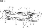
- Fig. 8 shows a further embodiment of an ultrasonic counter 1. This corresponds in many respects in the Figures 1 and 2 shown ultrasonic meter 1, which is why in the following only the differences should be explained.
- the measuring tube 16 is designed such that its wall thickness decreases at a fluid outlet-side end of the measuring tube 16, so that the outer surface 26 of the measuring tube 16 is spaced from an inner surface 25 of the housing 28 forming the outlet tube 17. This allows a backwashing of the fluid outlet-side end of the measuring tube 16, which may be advantageous from a fluidic point of view.
- Fig. 8 also shows a concrete possibility for fixing the reflection element 6.
- the reflection element 6 is supported by holding webs 27, which are arranged on an upper and lower peripheral portion 11, 13 of the transition region 9. They are thus arranged on peripheral portions 11, 13 which have a widening position located farthest downstream, whereby the flowing fluid in the region of the holding webs 27 can be brought as close as possible to the reflection element 6. This allows a robust control of the interaction of the guided flow with the retaining webs 27, which can be adjusted depending on the specific flow requirements.
Landscapes
- Physics & Mathematics (AREA)
- Fluid Mechanics (AREA)
- General Physics & Mathematics (AREA)
- Electromagnetism (AREA)
- Measuring Volume Flow (AREA)
Priority Applications (1)
| Application Number | Priority Date | Filing Date | Title |
|---|---|---|---|
| PL17001055T PL3267158T3 (pl) | 2016-07-06 | 2017-06-22 | Licznik ultradźwiękowy do rejestracji ilości przepływającego płynu |
Applications Claiming Priority (1)
| Application Number | Priority Date | Filing Date | Title |
|---|---|---|---|
| DE102016008302.6A DE102016008302A1 (de) | 2016-07-06 | 2016-07-06 | Ultraschallzähler zur Erfassung einer Durchflussmenge eines Fluids |
Publications (2)
| Publication Number | Publication Date |
|---|---|
| EP3267158A1 EP3267158A1 (de) | 2018-01-10 |
| EP3267158B1 true EP3267158B1 (de) | 2019-05-08 |
Family
ID=59152618
Family Applications (1)
| Application Number | Title | Priority Date | Filing Date |
|---|---|---|---|
| EP17001055.7A Active EP3267158B1 (de) | 2016-07-06 | 2017-06-22 | Ultraschallzähler zur erfassung einer durchflussmenge eines fluids |
Country Status (6)
| Country | Link |
|---|---|
| US (1) | US10359304B2 (pl) |
| EP (1) | EP3267158B1 (pl) |
| CN (1) | CN107588828B (pl) |
| DE (1) | DE102016008302A1 (pl) |
| DK (1) | DK3267158T3 (pl) |
| PL (1) | PL3267158T3 (pl) |
Families Citing this family (11)
| Publication number | Priority date | Publication date | Assignee | Title |
|---|---|---|---|---|
| PL3234514T3 (pl) * | 2015-08-28 | 2020-07-27 | Reliance Worldwide Corporation | Konfiguracja i kalibracja przepływomierza |
| DE102016013607B4 (de) * | 2016-11-15 | 2022-02-24 | Diehl Metering Gmbh | Ultraschallzähler |
| FR3080683B1 (fr) * | 2018-04-30 | 2023-03-17 | Buerkert Werke Gmbh & Co Kg | Moyen de mesure de fluide |
| DE102018112897A1 (de) * | 2018-05-30 | 2019-12-05 | Krohne Messtechnik Gmbh | Magnetisch-induktives Durchflussmessgerät und Messrohr |
| GB201808918D0 (en) | 2018-05-31 | 2018-07-18 | Sentec Ltd | Flow measurement improvement |
| DE102018005845B4 (de) * | 2018-07-25 | 2022-12-01 | Diehl Metering Gmbh | Ultraschallzähler |
| CN110108330B (zh) * | 2019-06-04 | 2024-09-24 | 武汉友讯达科技有限公司 | 水表测量管及超声波水表 |
| CN110530440A (zh) * | 2019-10-14 | 2019-12-03 | 中国计量大学 | 一种基于分流片在流体管道结构中的应用 |
| US12553753B2 (en) * | 2022-07-07 | 2026-02-17 | Badger Meter, Inc. | Ultrasonic flow meter including reflectors positioned by injection molding tool |
| CN116263350B (zh) * | 2022-12-19 | 2026-04-14 | 杭州水表有限公司 | 一种超声波水表基表及焊接辅助工装 |
| CN116086554B (zh) * | 2022-12-30 | 2026-03-17 | 金卡水务科技有限公司 | 双通道流量计量模组及超声波水表 |
Citations (1)
| Publication number | Priority date | Publication date | Assignee | Title |
|---|---|---|---|---|
| EP1693652A2 (de) * | 2005-02-17 | 2006-08-23 | Hydrometer GmbH | Durchflussmesser |
Family Cites Families (21)
| Publication number | Priority date | Publication date | Assignee | Title |
|---|---|---|---|---|
| EP0690974A4 (en) * | 1993-03-09 | 1996-05-22 | Commw Scient Ind Res Org | LIQUID METER DESIGN |
| JP2003114142A (ja) * | 2001-10-09 | 2003-04-18 | Fuji Electric Co Ltd | 超音波式ガスメータ |
| CN100504311C (zh) * | 2003-01-13 | 2009-06-24 | 塞德拉公司 | 使用超声波传感器阵列确定管道内的流体速度的设备和方法 |
| DK1978337T3 (da) * | 2003-06-13 | 2013-11-04 | Hydrometer Gmbh | Ultralydsmåler til bestemmelse af gennemstrømningsmængden af et strømmende medium |
| DK1701140T3 (da) * | 2005-03-11 | 2013-02-04 | Landis & Gyr Gmbh | Ultralydsmålekanal |
| EP1798528B1 (de) * | 2005-12-16 | 2012-08-08 | Hans-Holger Körner | Durchflussmengenmesseinrichtung für fluide Medien |
| DE102007011547B4 (de) * | 2007-03-09 | 2014-05-22 | Hydrometer Gmbh | Fluidzählanordnung |
| EP1995570A1 (en) * | 2007-05-25 | 2008-11-26 | Kamstrup A/S | An ultrasound flow meter |
| US7831398B2 (en) * | 2007-12-20 | 2010-11-09 | Expro Meters, Inc. | Method for quantifying varying propagation characteristics of normal incident ultrasonic signals as used in correlation based flow measurement |
| EP2270439B1 (en) * | 2009-07-03 | 2018-04-11 | Kamstrup A/S | Flow meter with moulded reflector unit |
| CN201707082U (zh) * | 2010-02-04 | 2011-01-12 | 威海米特智能仪表有限公司 | 容器整流防堵塞小压损易维护的超声波流量计基表 |
| DK177040B1 (en) * | 2010-04-12 | 2011-02-28 | Miitors Aps | Ultrasonic consumer meter with locking mechanism |
| US8904881B2 (en) | 2010-05-12 | 2014-12-09 | Hydrometer Gmbh | Ultrasound transducer assembly and ultrasound flowmeter |
| DE102010033858A1 (de) * | 2010-07-21 | 2012-01-26 | Hydrometer Gmbh | Gehäuse für eine Ultraschall-Messeinrichtung zur Messung eines Fluidflusses und Verfahren zur Herstellung eines Gehäuses |
| DK2423648T3 (en) * | 2010-08-31 | 2016-01-11 | Kamstrup As | Ultrasonic flow meter with effort maintained by a locking finger |
| CN202018311U (zh) * | 2011-01-26 | 2011-10-26 | 连云港水表有限公司 | 反射式超声波流量传感器 |
| EP2725327A1 (en) * | 2012-10-29 | 2014-04-30 | Kamstrup A/S | Ultrasonic flow meter with reflector surface with reduced symmetry |
| CN104061972B (zh) * | 2013-12-16 | 2017-02-08 | 北京德宝豪特能源科技有限公司 | 一种超声波液体流量测量装置 |
| DE102013114475B4 (de) * | 2013-12-19 | 2021-04-08 | Sick Ag | Ultraschallmessvorrichtung und Verfahren zum Bestimmen der Strömungsgeschwindigkeit |
| EP3172539B1 (en) * | 2014-07-21 | 2022-08-31 | Apator Miitors ApS | Flow conduit insert for an ultrasonic flowmeter |
| CN204854845U (zh) * | 2015-07-28 | 2015-12-09 | 青岛积成电子有限公司 | 一种超声波液体流量计管路 |
-
2016
- 2016-07-06 DE DE102016008302.6A patent/DE102016008302A1/de not_active Withdrawn
-
2017
- 2017-06-22 PL PL17001055T patent/PL3267158T3/pl unknown
- 2017-06-22 DK DK17001055.7T patent/DK3267158T3/da active
- 2017-06-22 EP EP17001055.7A patent/EP3267158B1/de active Active
- 2017-06-29 US US15/637,434 patent/US10359304B2/en active Active
- 2017-06-29 CN CN201710510878.3A patent/CN107588828B/zh active Active
Patent Citations (1)
| Publication number | Priority date | Publication date | Assignee | Title |
|---|---|---|---|---|
| EP1693652A2 (de) * | 2005-02-17 | 2006-08-23 | Hydrometer GmbH | Durchflussmesser |
Also Published As
| Publication number | Publication date |
|---|---|
| EP3267158A1 (de) | 2018-01-10 |
| DK3267158T3 (da) | 2019-08-12 |
| CN107588828A (zh) | 2018-01-16 |
| US20180010940A1 (en) | 2018-01-11 |
| CN107588828B (zh) | 2021-05-11 |
| DE102016008302A1 (de) | 2018-01-11 |
| PL3267158T3 (pl) | 2019-10-31 |
| US10359304B2 (en) | 2019-07-23 |
Similar Documents
| Publication | Publication Date | Title |
|---|---|---|
| EP3267158B1 (de) | Ultraschallzähler zur erfassung einer durchflussmenge eines fluids | |
| EP2172657B1 (de) | Strömungsrichter für ein Durchflussmessgerät, insbesondere ein Ultraschallmessgerät | |
| EP1975575B1 (de) | Durchflussmesser | |
| EP2565593B1 (de) | Ultraschallzähler | |
| EP3321645B1 (de) | Ultraschallzähler | |
| EP2827111B1 (de) | Ultraschallzähler | |
| EP3599446B1 (de) | Ultraschallzähler | |
| EP1613928A1 (de) | Differenzdruckmittel für eine gaszähleranordnung mit verbesserter strömungsgeometrie | |
| EP2811268A1 (de) | Durchflussmesser | |
| EP2172654B1 (de) | Kreiselpumpenaggregat | |
| DE102008042807A1 (de) | Vorrichtung zur Bestimmung eines Parameters eines strömenden fluiden Mediums | |
| EP3748309B1 (de) | Ultraschalldurchflussmessgerät, verwendung eines ultraschalldurchflussmessgerätes in einem absperrorgan und absperrorgan | |
| EP3665443B1 (de) | Durchflussmesser und messkanal | |
| EP3769052B1 (de) | Sensoranordnung | |
| EP4359737B1 (de) | Strömungsmesser | |
| EP3594634B1 (de) | Strömungsmesser | |
| DE102017117389B4 (de) | Strömungsmessvorrichtung | |
| EP3575753B1 (de) | Magnetisch-induktives durchflussmessgerät und messrohr | |
| EP3505875B1 (de) | Ultraschall-durchflussmessvorrichtung mit strömungsoptimiertem messrohr | |
| DE102008059510B4 (de) | Infusor und Durchflußmeßgerät | |
| DE102005018227A1 (de) | Durchflussmessgerät nach dem Vortex-Prinzip mit Strömungsgitter | |
| DE10240975A1 (de) | Meßwertgeber für einen Ultraschall-Durchflussmesser |
Legal Events
| Date | Code | Title | Description |
|---|---|---|---|
| PUAI | Public reference made under article 153(3) epc to a published international application that has entered the european phase |
Free format text: ORIGINAL CODE: 0009012 |
|
| STAA | Information on the status of an ep patent application or granted ep patent |
Free format text: STATUS: THE APPLICATION HAS BEEN PUBLISHED |
|
| AK | Designated contracting states |
Kind code of ref document: A1 Designated state(s): AL AT BE BG CH CY CZ DE DK EE ES FI FR GB GR HR HU IE IS IT LI LT LU LV MC MK MT NL NO PL PT RO RS SE SI SK SM TR |
|
| AX | Request for extension of the european patent |
Extension state: BA ME |
|
| STAA | Information on the status of an ep patent application or granted ep patent |
Free format text: STATUS: REQUEST FOR EXAMINATION WAS MADE |
|
| 17P | Request for examination filed |
Effective date: 20180614 |
|
| RBV | Designated contracting states (corrected) |
Designated state(s): AL AT BE BG CH CY CZ DE DK EE ES FI FR GB GR HR HU IE IS IT LI LT LU LV MC MK MT NL NO PL PT RO RS SE SI SK SM TR |
|
| REG | Reference to a national code |
Ref country code: DE Ref legal event code: R079 Ref document number: 502017001230 Country of ref document: DE Free format text: PREVIOUS MAIN CLASS: G01F0001660000 Ipc: G01F0025000000 |
|
| RIC1 | Information provided on ipc code assigned before grant |
Ipc: G01F 15/02 20060101ALI20181106BHEP Ipc: G01F 25/00 20060101AFI20181106BHEP Ipc: G01F 1/66 20060101ALI20181106BHEP Ipc: G01F 1/86 20060101ALI20181106BHEP |
|
| GRAP | Despatch of communication of intention to grant a patent |
Free format text: ORIGINAL CODE: EPIDOSNIGR1 |
|
| STAA | Information on the status of an ep patent application or granted ep patent |
Free format text: STATUS: GRANT OF PATENT IS INTENDED |
|
| INTG | Intention to grant announced |
Effective date: 20181214 |
|
| RIN1 | Information on inventor provided before grant (corrected) |
Inventor name: SONNENBERG, HANS-MICHAEL |
|
| GRAS | Grant fee paid |
Free format text: ORIGINAL CODE: EPIDOSNIGR3 |
|
| GRAA | (expected) grant |
Free format text: ORIGINAL CODE: 0009210 |
|
| STAA | Information on the status of an ep patent application or granted ep patent |
Free format text: STATUS: THE PATENT HAS BEEN GRANTED |
|
| AK | Designated contracting states |
Kind code of ref document: B1 Designated state(s): AL AT BE BG CH CY CZ DE DK EE ES FI FR GB GR HR HU IE IS IT LI LT LU LV MC MK MT NL NO PL PT RO RS SE SI SK SM TR |
|
| REG | Reference to a national code |
Ref country code: GB Ref legal event code: FG4D Free format text: NOT ENGLISH |
|
| REG | Reference to a national code |
Ref country code: CH Ref legal event code: EP Ref country code: AT Ref legal event code: REF Ref document number: 1130886 Country of ref document: AT Kind code of ref document: T Effective date: 20190515 |
|
| REG | Reference to a national code |
Ref country code: DE Ref legal event code: R096 Ref document number: 502017001230 Country of ref document: DE Ref country code: IE Ref legal event code: FG4D Free format text: LANGUAGE OF EP DOCUMENT: GERMAN |
|
| REG | Reference to a national code |
Ref country code: DK Ref legal event code: T3 Effective date: 20190807 |
|
| REG | Reference to a national code |
Ref country code: SE Ref legal event code: TRGR |
|
| REG | Reference to a national code |
Ref country code: NL Ref legal event code: MP Effective date: 20190508 |
|
| REG | Reference to a national code |
Ref country code: LT Ref legal event code: MG4D |
|
| PG25 | Lapsed in a contracting state [announced via postgrant information from national office to epo] |
Ref country code: FI Free format text: LAPSE BECAUSE OF FAILURE TO SUBMIT A TRANSLATION OF THE DESCRIPTION OR TO PAY THE FEE WITHIN THE PRESCRIBED TIME-LIMIT Effective date: 20190508 Ref country code: NO Free format text: LAPSE BECAUSE OF FAILURE TO SUBMIT A TRANSLATION OF THE DESCRIPTION OR TO PAY THE FEE WITHIN THE PRESCRIBED TIME-LIMIT Effective date: 20190808 Ref country code: AL Free format text: LAPSE BECAUSE OF FAILURE TO SUBMIT A TRANSLATION OF THE DESCRIPTION OR TO PAY THE FEE WITHIN THE PRESCRIBED TIME-LIMIT Effective date: 20190508 Ref country code: PT Free format text: LAPSE BECAUSE OF FAILURE TO SUBMIT A TRANSLATION OF THE DESCRIPTION OR TO PAY THE FEE WITHIN THE PRESCRIBED TIME-LIMIT Effective date: 20190908 Ref country code: HR Free format text: LAPSE BECAUSE OF FAILURE TO SUBMIT A TRANSLATION OF THE DESCRIPTION OR TO PAY THE FEE WITHIN THE PRESCRIBED TIME-LIMIT Effective date: 20190508 Ref country code: ES Free format text: LAPSE BECAUSE OF FAILURE TO SUBMIT A TRANSLATION OF THE DESCRIPTION OR TO PAY THE FEE WITHIN THE PRESCRIBED TIME-LIMIT Effective date: 20190508 Ref country code: NL Free format text: LAPSE BECAUSE OF FAILURE TO SUBMIT A TRANSLATION OF THE DESCRIPTION OR TO PAY THE FEE WITHIN THE PRESCRIBED TIME-LIMIT Effective date: 20190508 Ref country code: LT Free format text: LAPSE BECAUSE OF FAILURE TO SUBMIT A TRANSLATION OF THE DESCRIPTION OR TO PAY THE FEE WITHIN THE PRESCRIBED TIME-LIMIT Effective date: 20190508 |
|
| PG25 | Lapsed in a contracting state [announced via postgrant information from national office to epo] |
Ref country code: RS Free format text: LAPSE BECAUSE OF FAILURE TO SUBMIT A TRANSLATION OF THE DESCRIPTION OR TO PAY THE FEE WITHIN THE PRESCRIBED TIME-LIMIT Effective date: 20190508 Ref country code: BG Free format text: LAPSE BECAUSE OF FAILURE TO SUBMIT A TRANSLATION OF THE DESCRIPTION OR TO PAY THE FEE WITHIN THE PRESCRIBED TIME-LIMIT Effective date: 20190808 Ref country code: LV Free format text: LAPSE BECAUSE OF FAILURE TO SUBMIT A TRANSLATION OF THE DESCRIPTION OR TO PAY THE FEE WITHIN THE PRESCRIBED TIME-LIMIT Effective date: 20190508 Ref country code: GR Free format text: LAPSE BECAUSE OF FAILURE TO SUBMIT A TRANSLATION OF THE DESCRIPTION OR TO PAY THE FEE WITHIN THE PRESCRIBED TIME-LIMIT Effective date: 20190809 |
|
| PG25 | Lapsed in a contracting state [announced via postgrant information from national office to epo] |
Ref country code: CZ Free format text: LAPSE BECAUSE OF FAILURE TO SUBMIT A TRANSLATION OF THE DESCRIPTION OR TO PAY THE FEE WITHIN THE PRESCRIBED TIME-LIMIT Effective date: 20190508 Ref country code: RO Free format text: LAPSE BECAUSE OF FAILURE TO SUBMIT A TRANSLATION OF THE DESCRIPTION OR TO PAY THE FEE WITHIN THE PRESCRIBED TIME-LIMIT Effective date: 20190508 Ref country code: EE Free format text: LAPSE BECAUSE OF FAILURE TO SUBMIT A TRANSLATION OF THE DESCRIPTION OR TO PAY THE FEE WITHIN THE PRESCRIBED TIME-LIMIT Effective date: 20190508 Ref country code: SK Free format text: LAPSE BECAUSE OF FAILURE TO SUBMIT A TRANSLATION OF THE DESCRIPTION OR TO PAY THE FEE WITHIN THE PRESCRIBED TIME-LIMIT Effective date: 20190508 |
|
| REG | Reference to a national code |
Ref country code: DE Ref legal event code: R097 Ref document number: 502017001230 Country of ref document: DE |
|
| PG25 | Lapsed in a contracting state [announced via postgrant information from national office to epo] |
Ref country code: MC Free format text: LAPSE BECAUSE OF FAILURE TO SUBMIT A TRANSLATION OF THE DESCRIPTION OR TO PAY THE FEE WITHIN THE PRESCRIBED TIME-LIMIT Effective date: 20190508 Ref country code: IT Free format text: LAPSE BECAUSE OF FAILURE TO SUBMIT A TRANSLATION OF THE DESCRIPTION OR TO PAY THE FEE WITHIN THE PRESCRIBED TIME-LIMIT Effective date: 20190508 Ref country code: SM Free format text: LAPSE BECAUSE OF FAILURE TO SUBMIT A TRANSLATION OF THE DESCRIPTION OR TO PAY THE FEE WITHIN THE PRESCRIBED TIME-LIMIT Effective date: 20190508 |
|
| PLBE | No opposition filed within time limit |
Free format text: ORIGINAL CODE: 0009261 |
|
| STAA | Information on the status of an ep patent application or granted ep patent |
Free format text: STATUS: NO OPPOSITION FILED WITHIN TIME LIMIT |
|
| REG | Reference to a national code |
Ref country code: BE Ref legal event code: MM Effective date: 20190630 |
|
| PG25 | Lapsed in a contracting state [announced via postgrant information from national office to epo] |
Ref country code: TR Free format text: LAPSE BECAUSE OF FAILURE TO SUBMIT A TRANSLATION OF THE DESCRIPTION OR TO PAY THE FEE WITHIN THE PRESCRIBED TIME-LIMIT Effective date: 20190508 |
|
| 26N | No opposition filed |
Effective date: 20200211 |
|
| PG25 | Lapsed in a contracting state [announced via postgrant information from national office to epo] |
Ref country code: IE Free format text: LAPSE BECAUSE OF NON-PAYMENT OF DUE FEES Effective date: 20190622 |
|
| PG25 | Lapsed in a contracting state [announced via postgrant information from national office to epo] |
Ref country code: LU Free format text: LAPSE BECAUSE OF NON-PAYMENT OF DUE FEES Effective date: 20190622 Ref country code: BE Free format text: LAPSE BECAUSE OF NON-PAYMENT OF DUE FEES Effective date: 20190630 Ref country code: SI Free format text: LAPSE BECAUSE OF FAILURE TO SUBMIT A TRANSLATION OF THE DESCRIPTION OR TO PAY THE FEE WITHIN THE PRESCRIBED TIME-LIMIT Effective date: 20190508 |
|
| REG | Reference to a national code |
Ref country code: CH Ref legal event code: PL |
|
| PG25 | Lapsed in a contracting state [announced via postgrant information from national office to epo] |
Ref country code: LI Free format text: LAPSE BECAUSE OF NON-PAYMENT OF DUE FEES Effective date: 20200630 Ref country code: CH Free format text: LAPSE BECAUSE OF NON-PAYMENT OF DUE FEES Effective date: 20200630 |
|
| PG25 | Lapsed in a contracting state [announced via postgrant information from national office to epo] |
Ref country code: CY Free format text: LAPSE BECAUSE OF FAILURE TO SUBMIT A TRANSLATION OF THE DESCRIPTION OR TO PAY THE FEE WITHIN THE PRESCRIBED TIME-LIMIT Effective date: 20190508 |
|
| PG25 | Lapsed in a contracting state [announced via postgrant information from national office to epo] |
Ref country code: IS Free format text: LAPSE BECAUSE OF FAILURE TO SUBMIT A TRANSLATION OF THE DESCRIPTION OR TO PAY THE FEE WITHIN THE PRESCRIBED TIME-LIMIT Effective date: 20190908 |
|
| PG25 | Lapsed in a contracting state [announced via postgrant information from national office to epo] |
Ref country code: MT Free format text: LAPSE BECAUSE OF FAILURE TO SUBMIT A TRANSLATION OF THE DESCRIPTION OR TO PAY THE FEE WITHIN THE PRESCRIBED TIME-LIMIT Effective date: 20190508 Ref country code: HU Free format text: LAPSE BECAUSE OF FAILURE TO SUBMIT A TRANSLATION OF THE DESCRIPTION OR TO PAY THE FEE WITHIN THE PRESCRIBED TIME-LIMIT; INVALID AB INITIO Effective date: 20170622 |
|
| GBPC | Gb: european patent ceased through non-payment of renewal fee |
Effective date: 20210622 |
|
| PG25 | Lapsed in a contracting state [announced via postgrant information from national office to epo] |
Ref country code: GB Free format text: LAPSE BECAUSE OF NON-PAYMENT OF DUE FEES Effective date: 20210622 |
|
| PG25 | Lapsed in a contracting state [announced via postgrant information from national office to epo] |
Ref country code: MK Free format text: LAPSE BECAUSE OF FAILURE TO SUBMIT A TRANSLATION OF THE DESCRIPTION OR TO PAY THE FEE WITHIN THE PRESCRIBED TIME-LIMIT Effective date: 20190508 |
|
| PGFP | Annual fee paid to national office [announced via postgrant information from national office to epo] |
Ref country code: PL Payment date: 20250613 Year of fee payment: 9 |
|
| PGFP | Annual fee paid to national office [announced via postgrant information from national office to epo] |
Ref country code: DK Payment date: 20250625 Year of fee payment: 9 |
|
| PGFP | Annual fee paid to national office [announced via postgrant information from national office to epo] |
Ref country code: FR Payment date: 20250625 Year of fee payment: 9 |
|
| PGFP | Annual fee paid to national office [announced via postgrant information from national office to epo] |
Ref country code: AT Payment date: 20250620 Year of fee payment: 9 |
|
| PGFP | Annual fee paid to national office [announced via postgrant information from national office to epo] |
Ref country code: SE Payment date: 20250618 Year of fee payment: 9 |
|
| PGFP | Annual fee paid to national office [announced via postgrant information from national office to epo] |
Ref country code: DE Payment date: 20250814 Year of fee payment: 9 |