EP3267162A1 - Wärmeflussratenmesser - Google Patents
Wärmeflussratenmesser Download PDFInfo
- Publication number
- EP3267162A1 EP3267162A1 EP16758714.6A EP16758714A EP3267162A1 EP 3267162 A1 EP3267162 A1 EP 3267162A1 EP 16758714 A EP16758714 A EP 16758714A EP 3267162 A1 EP3267162 A1 EP 3267162A1
- Authority
- EP
- European Patent Office
- Prior art keywords
- heat
- transfer element
- sensor
- pipe
- flux
- Prior art date
- Legal status (The legal status is an assumption and is not a legal conclusion. Google has not performed a legal analysis and makes no representation as to the accuracy of the status listed.)
- Withdrawn
Links
Images





Classifications
-
- G—PHYSICS
- G01—MEASURING; TESTING
- G01F—MEASURING VOLUME, VOLUME FLOW, MASS FLOW OR LIQUID LEVEL; METERING BY VOLUME
- G01F1/00—Measuring the volume flow or mass flow of fluid or fluent solid material wherein the fluid passes through a meter in a continuous flow
- G01F1/68—Measuring the volume flow or mass flow of fluid or fluent solid material wherein the fluid passes through a meter in a continuous flow by using thermal effects
- G01F1/684—Structural arrangements; Mounting of elements, e.g. in relation to fluid flow
-
- G—PHYSICS
- G01—MEASURING; TESTING
- G01F—MEASURING VOLUME, VOLUME FLOW, MASS FLOW OR LIQUID LEVEL; METERING BY VOLUME
- G01F1/00—Measuring the volume flow or mass flow of fluid or fluent solid material wherein the fluid passes through a meter in a continuous flow
- G01F1/68—Measuring the volume flow or mass flow of fluid or fluent solid material wherein the fluid passes through a meter in a continuous flow by using thermal effects
- G01F1/684—Structural arrangements; Mounting of elements, e.g. in relation to fluid flow
- G01F1/6847—Structural arrangements; Mounting of elements, e.g. in relation to fluid flow where sensing or heating elements are not disturbing the fluid flow, e.g. elements mounted outside the flow duct
-
- G—PHYSICS
- G01—MEASURING; TESTING
- G01F—MEASURING VOLUME, VOLUME FLOW, MASS FLOW OR LIQUID LEVEL; METERING BY VOLUME
- G01F1/00—Measuring the volume flow or mass flow of fluid or fluent solid material wherein the fluid passes through a meter in a continuous flow
- G01F1/68—Measuring the volume flow or mass flow of fluid or fluent solid material wherein the fluid passes through a meter in a continuous flow by using thermal effects
- G01F1/684—Structural arrangements; Mounting of elements, e.g. in relation to fluid flow
- G01F1/688—Structural arrangements; Mounting of elements, e.g. in relation to fluid flow using a particular type of heating, cooling or sensing element
-
- G—PHYSICS
- G01—MEASURING; TESTING
- G01K—MEASURING TEMPERATURE; MEASURING QUANTITY OF HEAT; THERMALLY-SENSITIVE ELEMENTS NOT OTHERWISE PROVIDED FOR
- G01K13/00—Thermometers specially adapted for specific purposes
- G01K13/02—Thermometers specially adapted for specific purposes for measuring temperature of moving fluids or granular materials capable of flow
-
- H—ELECTRICITY
- H10—SEMICONDUCTOR DEVICES; ELECTRIC SOLID-STATE DEVICES NOT OTHERWISE PROVIDED FOR
- H10N—ELECTRIC SOLID-STATE DEVICES NOT OTHERWISE PROVIDED FOR
- H10N10/00—Thermoelectric devices comprising a junction of dissimilar materials, i.e. devices exhibiting Seebeck or Peltier effects
- H10N10/01—Manufacture or treatment
Definitions
- the present invention relates to a thermal flow-rate sensor that detects a flow rate of a measurement medium that flows inside a pipe.
- this thermal flow-rate sensor includes a first temperature sensor, a heat-transfer element, and a second temperature sensor.
- the first temperature sensor detects the temperature of a measurement medium that flows inside a pipe by detecting the temperature of the pipe.
- the heat-transfer element is arranged further on the downstream side in the direction of flow of the measurement medium than the first temperature sensor, and exchanges heat with the measurement medium (pipe).
- the second temperature sensor detects the temperature of the outside air. So as not to be affected by the temperature of a portion that exchanges heat with the heat-transfer element inside the pipe, the first temperature sensor is arranged so as to be sufficiently separated from the heat-transfer element.
- the temperature of the outside air is detected by the second temperature sensor, and the heat flux between the heat-transfer element and the pipe is calculated based on the temperature of the outside air.
- Patent Document 1 Japanese Patent Application Publication No. 2004-69667
- the object of the present invention is to provide a thermal flow-rate sensor that is able to suppress a detection precision from dropping.
- One form of the thermal flow-rate sensor of the present invention includes: a first temperature sensor that detects the temperature of a measurement medium that is flowing through a passageway inside a pipe by detecting the temperature at a specified location of an outer-wall surface of the pipe; a heat-transfer element that is arranged on the outer-wall surface of the pipe in a state separated from the first temperature sensor, and that exchanges heat with the measurement medium by heating or cooling the outer-wall surface of the pipe; a second temperature sensor that detects the temperature of a portion of the outer-wall surface of the pipe that is heated or cooled by the heat-transfer element; and a control unit that performs specified processing.
- a heat-flux sensor is arranged between the heat-transfer element and the outer-wall surface of the pipe and detects heat flux between the heat-transfer element and the pipe; and the control unit detects the flow rate of the measurement medium based on the temperature that is detected by the first temperature sensor, the temperature that is detected by the second temperature sensor, and the heat flux that is detected by the heat-flux sensor.
- the heat-flux sensor is arranged between the heat-transfer element and the outer-wall surface of the pipe, and the heat-flux directly detects heat flux between the heat-transfer element and the pipe. Therefore, it is possible to suppress the detection precision from dropping for detecting heat flux, and to suppress the detection precision from dropping for detecting the flow rate of the measurement medium.
- a thermal flow-rate sensor of the present embodiment is a sensor that detects a flow rate of a measurement medium that flows inside a pipe 10; and as illustrated in FIG. 1 , the thermal flow-rate sensory includes a first temperature sensor 20 and a second temperature sensor 30 that detect temperature, a heat-flux sensor 40 that detects heat flux, a heat-transfer element 50 that heats the pipe 10, and a control unit 60.
- the pipe 10 is made of metal member such as SUS or the like, and has a passageway 11 inside of which a measurement medium flows.
- a measurement medium flows inside the pipe 10
- the direction of flow of the measurement medium that flows inside the pipe 10 will be explained as being from the left side to the right side of the drawing surface.
- the first temperature sensor 20 and second temperature sensor 30 include a thermistor or the like, and are arranged on an outer-wall surface of the pipe 10 so as to be separated from each other.
- the first temperature sensor 20 is arranged further on the upstream side (left side of the surface in FIG. 1 ) in the direction of flow of the measurement medium than the second temperature sensor 30.
- the first temperature sensor 20 and the second temperature sensor 30 are connected to the control unit 60, and each sensor outputs a detection signal according to the temperature of the outer-wall surface of the pipe 10 where the sensor is arranged.
- the first temperature sensor 20 detects the temperature of a portion of the outer-wall surface of the pipe 10 that is not heated by the heat-transfer element 50
- the second temperature sensor 30 detects the temperature of a portion of the outer-wall surface of the pipe 10 that is heated by the heat-transfer element 50.
- the first temperature sensor 20 is arranged further on the upstream side in the direction of flow of the measurement medium than the second temperature sensor 30 is, and is arranged so as to be sufficiently separated from the second temperature sensor 30 (heat-transfer element 50).
- the heat-flux sensor 40 is arranged on the second temperature sensor 30 and is connected to the control unit 60. As will be described in detail later, the heat-transfer element 50 is arranged on the heat-flux sensor 40, and outputs a detection signal according to the heat flux between the heat-transfer element 50 and the pipe 10 to the control unit 60.
- the configuration of the heat-flux sensor 40 of the present embodiment will be explained in detail.
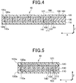
- the heat-flux sensor 40 is configured such that an insulating substrate 100, a rear-surface-protective member 110, and a front-surface-protective member 120 are integrated into a single body, and inside this integrated body, first and second interlayer-connecting members 130, 140 are connected together in series in the present embodiment.
- first and second interlayer-connecting members 130, 140 are connected together in series in the present embodiment.
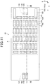
- FIG. 2 for easy understanding, the rear-surface-protective member 110 is omitted.
- the front-surface-protective member 120 is omitted.
- FIG. 2 and FIG. 3 are not cross-sectional views, however, the first and second interlayer-connecting members 130, 140 are illustrated with hatching.
- the insulating substrate 100 includes a planar rectangular shaped thermoplastic resin film that is represented by polyetheretherketone (PEEK), polyetherimide (PEI), and liquid-crystal polymer (LCP) in the present embodiment.
- PEEK polyetheretherketone
- PEI polyetherimide
- LCP liquid-crystal polymer
- a plurality of first and second via holes 101, 102 that penetrate in the thickness direction Z are formed in a zigzag pattern so as to be staggered.
- the first and second via holes 101, 102 are formed into a cylindrical shape with a fixed diameter from the front surface 100a to the rear surface 100b of the insulating substrate 100 (refer to FIG. 4 and FIG. 5 ), however, the first and second via holes 101, 102 may also be formed in a taper shape of which the diameter becomes smaller going from the front surface 100a toward the rear surface 100b. Moreover, the first and second via holes 101, 102 may also be formed in a taper shape of which the diameter becomes smaller going from the rear surface 100b toward the front surface 100a.
- the first interlayer-connecting members 130 are arranged in the first via holes 101, and the second interlayer-connecting members 140 are arranged in the second via holes 102.
- the first and second interlayer-connecting members 130, 140 are arranged in the insulating substrate 100 so as to be staggered with respect to each other.
- the first and second interlayer-connecting members 130, 140 are made of metals that are different from each other in order to obtain a Seebeck effect.
- the first interlayer-connecting members 130 are made of a solid-phase sintered metal compound (sintered alloy) so that P-type Bi-Sb-Te alloy powder maintains the crystal structure of a plurality of metal atoms before sintering.
- the second interlayer-connecting members 140 are made of a solid-phase sintered metal compound (sintered alloy) so that N-type Bi-Te alloy powder maintains a specified crystal structure of a plurality of metal atoms before sintering. In this way, by using solid-phase sintered metal compounds as the first and second interlayer-connecting members 130, 140 so that specified crystal structures are maintained, it is possible to increase the induced voltage.
- the rear-surface-protective member 110 is arranged on the rear surface 100b of the insulating substrate 100.
- the rear-surface-protective member 110 includes, for example, a planar rectangular shaped thermoplastic resin film that is represented by polyetheretherketone (PEEK), polyetherimide (PEI), and liquid-crystal polymer (LCP).
- PEEK polyetheretherketone
- PEI polyetherimide
- LCP liquid-crystal polymer
- This rear-surface-protective member 110 is such that the dimensions of the planar shape are the same as those of the insulating substrate 100, and copper foil or the like that is patterned with a plurality of rear-surface patterns 111 that are separated from each other is formed on the one surface 110a side that faces the insulating substrate 100.
- Each rear-surface pattern 111 is suitably and electrically connected to both the first and second interlayer-connecting members 130, 140.
- each set 150 of the first and second interlayer-connecting members 130, 140 is connected to the same rear-surface pattern 111.
- each set 150 of the first and second interlayer-connecting members 130, 140 is electrically connected via a rear-surface pattern 111.
- one first interlayer-connecting member 130 and one second interlayer-connecting member 140 that are adjacent in the lengthwise direction X of the insulating substrate 100 form one set 150.
- a front-surface-protective member 120 is arranged on the front surface 100a of the insulating substrate 100.
- the front-surface-protective member 120 includes, for example, a planar rectangular shaped thermoplastic resin film that is represented by polyetheretherketone (PEEK), polyetherimide (PEI), and liquid-crystal polymer (LCP).
- PEEK polyetheretherketone
- PEI polyetherimide
- LCP liquid-crystal polymer
- the first interlayer-connecting member 130 of one set 150 and the second interlayer-connecting member of the other set 150 are connected to the same front-surface pattern 121.
- the first and second interlayer-connecting members 130, 140 are electrically connected via a front surface pattern 121 across the sets 150.
- the first and second interlayer-connecting members 130, 140 that are adjacent along the direction Y that is orthogonal to the lengthwise direction X, are connected to the same front-surface pattern 121.
- the adjacent first and second interlayer-connecting members 130, 140 are connected to the same front-surface pattern 121 so that the first and second interlayer-connecting members 130, 140 that are connected in series via the front-surface pattern 121 and the rear-surface patter 111 in the lengthwise direction of the insulating substrate 100 are folded back.
- the first and second interlayer-connecting members 130, 140 end sections of which are connected in series as described above (the first interlayer-connecting member 130 on the lower right of the drawing surface in FIG. 3 , and the second interlayer-connecting member 140 on the upper right of the drawing surface in FIG. 3 ) are connected to a connecting pattern 122.
- the heat-transfer element 50 is arranged on the heat-flux sensor 40, and in FIG. 3 , a portion that faces the heat-transfer element 50 (a portion positioned directly below) is illustrated as an area A.
- the two connecting patterns 122 are such that the end sections that are on the opposite side from the side that is connected to the respective first and second interlayer-connecting members 130, 140 are extended to the outside of the area A.
- a portion that faces the heat-transfer element 50 is illustrated as the area A.
- connecting holes 160 are formed in the front-surface-protective member 120 so that end sections of the connecting patterns 122 that extend to the outside of the area A are exposed.
- the heat-flux sensor 40 can be electrically connected to the control unit 60 via the connecting holes 160.
- the configuration of the heat-flux sensor 40 of the present embodiment is as described above.
- the heat-flux sensor 40 described above is such that when the heat flux that is passing through the heat-flux sensor 40 in the thickness direction Z changes, the induced voltage that occurs in the first and second interlayer-connecting members 130, 140 that are connected in series with each other changes, so that induced voltage is outputted to the control unit 60 as a detection signal.
- the thickness direction Z of the heat-flux sensor 40 is the layering direction of the insulating substrate 100, the front-surface-protective member 120, and the rear-surface-protective member 110.
- this kind of heat-flux sensor 40 is manufactured by a so-called PALAP (registered trademark) manufacturing method.
- PALAP registered trademark
- the first and second via holes 101, 102 are formed in the insulating substrate 100, and conductive paste of the first and second interlayer-connecting members 130, 140 is filled into the first and second via holes 101, 102.
- the rear-surface-protective member 110 in which rear-surface patterns 111 are formed, and the front-surface-protective member 120 in which front-surface patterns 121 and connecting patterns 122 are formed are prepared.
- a laminate is formed by layering the rear-surface-protective member 110, the insulating substrate 100, and the front-surface-protective member 120 in this order so that the conductive paste that is filled in the first and second via holes 101, 102 comes in suitable contact with the front-surface patterns 121 and the rear-surface patterns 111.
- the heat-flux sensor 40 is manufactured by applying pressure to the rear-surface-protective member 110, the insulating substrate 100, and the front-surface-protective member 120 in the layering direction (thickness direction Z) while heating the laminate in order to form a single body, forming the first and second interlayer-connecting members 130, 140 from the conductive paste.
- the heat-flux sensor 40 described above is arranged on the second temperature sensor 30 (the outer wall surface of the pipe 10) via a heat-conducting member 70 that is arranged so as to cover the second temperature sensor 30.
- the heat-conducting member 70 is a heat-conducting member such as grease, gel sheet or the like that has flexibility, and is being arranged along the outer-wall surface of the pipe 10, and a side opposite from the pipe 10 has a shape (surface) that runs along the pipe 10.
- the heat-flux sensor 40 is arranged via the heat-conducting member 70 so that the rear-surface-protective member 110 side is the heat-conducting member 70 side, and so that there is no gap (space) between the heat-flux sensor 40 and the heat-conducting member 70.
- the heat-conducting member 70 is arranged so that between the heat-flux sensor 40 and outer-wall surface of the pipe 10 (second temperature sensor 30) is completely sealed.
- the heat-flux sensor 40 has flexibility because the insulating substrate 100, front-surface-protective member 120, and rear-surface-protective member 110 are configured of a thermoplastic resin. Therefore, the heat-flux sensor 40 is arranged in a shape along the heat-conducting member 70 (foundation).
- the heat-transfer element 50 in the present embodiment, includes an electric heater that heats by electrical conduction, and is arranged on the heat-flux sensor 40.
- the heat-transfer element 50 is arranged on the outer-wall surface of the pipe 10 so that the heat-flux sensor 40 is arranged between the heat-transfer element 50 and the outer-wall surface of the pipe 10.
- the heat-transfer element 50 performs heat exchange with the measurement medium by heating a portion of the outer-wall surface of the pipe 10 that faces the heat-transfer element 50 via the heat-flux sensor 40, the heat-conducting member 70, the second temperature sensor 30, and areas around that portion.
- the second temperature sensor 30 detects the temperature of a portion of the outer-wall surface of the pipe 10 that is heated by the heat-transfer element 50, and the heat-flux sensor 40 directly detects the heat flux between heat-transfer element 50 and the outer-wall surface of the pipe 10.
- the first temperature sensor 20 is arranged in a position that is sufficiently separated from the portion of the outer-wall surface of the pipe 10 that is heated by the heat-transfer element 50 as described above, and detects the temperature of the portion that is not heated by the heat-transfer element 50.
- the heat-transfer element 50 has a rectangular shape of which the planar shape dimensions are smaller than those of the heat-flux sensor 40.
- the heat-transfer element 50 is arranged so as to be positioned inside the heat-flux sensor 40 (the area A in FIG. 2 and FIG. 3 ).
- the end sections that form the outer shape of the heat-transfer element 50 are arranged so as not to protrude from the heat-flux sensor 40.
- a heat-insulating member 80 that includes glass wool, foamed urethane, or the like is arranged so as to cover the first temperature sensor 20 and second temperature sensor 30, the heat-flux sensor 40, the heat-transfer element 50, and the heat-conducting member 70.
- the heat-insulating member 80 a ring-shaped member is illustrated that covers the first temperature sensor 20 and second temperature sensor 30, the heat-flux sensor 40, the heat-transfer element 50 and the heat-conducting member 70, however, a member may be used that covers only specified locations of the pipe 10 where the first temperature sensor 20 and second temperature sensor 30, the heat-flux sensor 40, the heat-transfer element 50 and the heat-conducting member 70 are arranged.
- the control unit 60 is configured of a CPU, various memories of storage means, peripheral devices and the like.
- the control unit 60 detects the flow rate of a measurement medium that flows inside the passage 11 of the pipe 10 by performing specified processing. More specifically, when detections signals detected by the first temperature sensor 20, the second temperature sensor 30, and the heat-flux sensor 40 are inputted, the control unit 60 uses these detection signals to detect the flow rate of the measurement medium that flows inside the passageway 11 of the pipe 10.
- the control unit 60 corresponds to the control unit of the present invention.
- the thermal flow-rate sensor of the present embodiment is configured as described above. Next, the operation of the thermal flow-rate sensor described above will be explained.
- the thermal flow-rate sensor such as described above, when the heat-transfer element 50 generates heat, the portion of the pipe 10 that faces the heat-transfer element 50 (portion positioned directly below) and the area near that portion are heated. Then, the heat that is generated in the heat-transfer element 50 is transferred to the pipe 10 via the heat-flux sensor 40 (heat flux passes through the heat-flux sensor 40). Therefore, a detection signal is outputted from the heat-flux sensor 40 to the control unit 60 according to the heat flux that passes trough the heat-flux sensor 40. In other words, the heat flux between the heat-flux sensor 40 and the outer-wall surface of the pipe 10 is directly detected by the heat-flux sensor 40.
- a detection signal according to the temperature of the outer-wall surface of the pipe 10 that is not heated by the heat-transfer element 50 is outputted from the first-temperature sensor 20 to the control unit 60. Then a detection signal according to the temperature of the portion of the outer-wall surface of the pipe 10 that is heated by the heat-transfer element 50 is outputted from the second temperature sensor 30 to the control unit 60.
- the heat-transfer coefficient from the pipe 10 to the measurement medium is taken to be h
- the temperature of the measurement medium is taken to be T1
- the temperature of the wall surface that is heated by the heat-transfer element 50 is taken to be T2
- the equation Q h(T2 - T0) is established.
- the temperature of the portion of the outer-wall surface of the pipe 10 that is not heated by the heat-transfer element 50 can be presumed to be equal to the temperature of the measurement medium.
- the temperature T1 of the measurement medium is detected by the first temperature sensor 20.
- the control unit 60 first calculates the heat-transfer coefficient by using the detected heat flux Q, the temperature of the measurement medium T1, and the temperature of the heated portion of the wall surface T2. Moreover, the heat-transfer coefficient h and the flow velocity of the measurement medium have a correlation, so the flow velocity is calculated from the correlation between the calculated heat-transfer coefficient h and the flow velocity of the measurement medium. Then, by performing calculation (multiplication) based on the cross-sectional area of the pipe that is a specified value, and the flow velocity of the measurement medium, the flow rate of the measurement medium is calculated. The flow rate of the measurement medium is calculated as described above.
- the heat-transfer element 60 has a rectangular shape with the dimensions of the planar shape being smaller than those of the heat-flux sensor 40. Also, when viewed from the layering direction (thickness direction Z) of the heat-transfer element 50 and heat-flux sensor 40, the heat-transfer element 50 is positioned so as to be inside the heat-flux sensor 40. Therefore, the detection precision of the heat-flux sensor 40 is further prevented from decreasing.
- the heat-transfer element 50 has a rectangular shape, and the dimensions of the planar shape of which are less than those of the heat-flux sensor 40. Also, when viewed from the layering direction (thickness direction Z) of the heat-transfer element 50 and the heat-flux sensor 40, the heat-transfer element 50 is arranged so as to be positioned inside the heat-flux sensor 40. Therefore, heat that is generated in the heat-transfer element 50 uniformly passes through the heat-flux sensor 40, so it is possible to suppress a the detection precision from dropping.
- the heat-conducting member 70 is arranged between the heat-flux sensor 40 and the pipe 10 so that no gaps (spaces) are formed. Therefore, heat that is generated in the heat-transfer element 50 is uniformly transmitted to the pipe 10 via the heat-flux sensor 40 and the heat-conducting member 70. As a result, it is possible to suppress the detection precision of the heat-flux sensor 40 from dropping. Moreover, the heat that is generated in the heat-transfer element 50 is uniformly transmitted to the pipe 10 via the heat-flux sensor 40 and the heat-conducting member 70. As a result, it is possible to prevent an error from occurring between the temperature of the heated portion of the outer-wall surface of the pipe 10 and the heat flux that passes through the heat-flux sensor 40.
- the heat-flux sensor 40 is arranged between the heat-transfer element 50 and the outer-wall surface of the pipe 10, and the heat-flux sensor 40 directly detects the heat flux between the heat-transfer element50 and the pipe 10. Therefore, it is possible to suppress the detection precision for detecting the heat flux from dropping, and it is possible to suppress the detection precision for detecting the flow rate of the measurement medium from dropping.
- the heat-transfer element 50 has a rectangular shape with the dimensions of the planar shape being smaller than those of the heat-flux sensor 40. Moreover, when viewed from the layering direction (thickness direction Z) of the heat-transfer element 50 and the heat-flux sensor 40, the heat-transfer element 50 is arranged so as to be positioned inside the heat-flux sensor 40. Therefore, heat that is generated in the heat-transfer element 50 uniformly passes through the heat-flux sensor 40. As a result, when compared with a case in which the end sections that form the outer shape of the heat-transfer element 50 protrude from the heat-flux sensor 40, it is possible to suppress the detection precision of the heat-flux sensor 40 from dropping.
- a second embodiment of the present invention will be explained.
- an arrangement location of a second temperature sensor 30 is changed from that of the first embodiment, however, the other parts are the same as those of the first embodiment, so an explanation of those parts will be omitted here.
- the heat-flux sensor 40 is arranged directly on the outer-wall surface of the pipe 10.
- configuration is such that a heat-conducting member 70 is not arranged between the heat-flux sensor 40 and the pipe 10.
- the second temperature sensor 30 is arranged near the heat-flux sensor 40. More specifically, the second temperature sensor 30 is not arranged in a portion of the outer-wall surface of the pipe 10 that faces the heat-transfer element 50. However, the second temperature sensor 30 is arranged at a location where it is possible to detect the temperature of a portion of the outer-wall surface of the pipe 10 that is heated by the heat-transfer element 50.
- the second temperature sensor 30 does not need to be arranged at a portion of the outer-wall surface of the pipe 10 that faces the heat-transfer element 50.
- the second temperature sensor 30 is arranged in this way, it is possible to arrange the heat-flux sensor 40 directly on the pipe 10, so there is no need to arrange a heat-conducting member 70, which makes it possible to reduce the number of parts.
- the present embodiment differs from the first embodiment in that the second temperature sensor 30 and the heat-flux sensor 40 are integrated into a single body, however, the other parts are the same as those of the first embodiment, so an explanation of those parts will be omitted here.
- the second temperature sensor 30 and the heat-flux sensor are integrated into a single body. More specifically, the second temperature sensor 30 is arranged between the insulating substrate 100 and the rear-surface-protective member 110, and is arranged so as to be inside the area A. In FIG. 7 , in order to make it easier to understand, the rear-surface-protective member 110 is omitted. Moreover, in FIG. 8 , in order to make it easier to understand, the front-surface-protective member 120 is omitted. FIG. 7 and FIG. 8 are not cross-sectional views, however, the first and second interlayer-connecting members 130, 140, and a third interlayer-connecting member 170 that will be described later are indicated by hatching.
- Third via holes 103 that are similar to the first and second via holes 101, 102 are formed in the insulating member 100.
- a third interlayer-connecting member 170 that is a sintered metal and similar to the first and second interlayer-connecting members 130, 140 is arranged in the third via holes 103.
- the third via holes 103 are formed so as to expose the second temperature sensor 30, and the third interlayer-connecting member 170 is arranged so as to be electrically connected with the second temperature sensor 30.
- two connecting patterns 123 that are similar to the connecting patterns 122 are formed in the front-surface-protective member 120.
- the connecting patterns 123 are such that the end sections on the opposite side from the side that is connected to the third interlayer-connecting member 170 extend to the outside of the area A.
- a connecting hole 161 that exposes end sections of the extended connecting patterns 123 similar to the connecting hole 160 is formed in the front-surface-protective member 120. In this way, the heat-flux sensor 40 can be electrically connected to the control unit 60 via the connecting hole 161.
- the configuration of the third interlayer-connecting member 170 may be the same as the configuration of the first and second interlayer-connecting members 130, 140, however, the third interlayer-connecting member 170 may be suitably changed as long as an electrical connection with the second temperature sensor 30 and connecting patterns 123 is possible.
- this kind of integrated second temperature sensor 30 and heat-flux sensor 40 are arranged directly on the outer-wall surface of the pipe 10 so that the front-surface-protective member 110 side of the heat-flux sensor 40 faces the outer-wall surface of the pipe 10.
- the second temperature sensor 30 and the heat-flux sensor 40 are integrated into a single body. Therefore, when installing the second temperature sensor 30 and the heat-flux sensor 40 to the outer-wall surface of the pipe 10, it is possible to obtain the same effect as that of the first embodiment while suppressing the shifting of the positions of the second temperature sensor 30 and the heat-flux sensor 40 from occurring.
- a fourth embodiment of the present invention will be explained.
- the present embodiment differs from the third embodiment in that the first temperature sensor 20 is also integrated with the heat-flux sensor 40 into a single body, however, the other parts are the same as those of the first embodiment, so an explanation of those parts will be omitted here.
- the first temperature sensor 20, together with the second temperature sensor 30, is integrated with the heat-flux sensor 40. More specifically, the first temperature sensor 20 is arranged between the insulating member 100 and the rear-surface-protective member 110, and is arranged so as to be positioned on the outside of the area A.
- the first temperature sensor 20 In order the first temperature sensor 20 not to be affected by the heat-transfer element 50, the first temperature sensor 20 is arranged outside of the area A, and is arranged at a position that is sufficiently separated from area A. Moreover, in FIG. 10 , in order to make it easier to understand, the rear-surface-protective member 110 is omitted. Furthermore, in FIG. 11 , in order to make it easier to understand, the front-surface-protective member 120 is omitted. FIG. 10 and FIG. 11 are not cross-sectional views, however, the first to third interlayer-connecting members 130, 140, 170 and a fourth interlayer-connecting member 180 that will be described later are indicated by hatching.
- a fourth via hole 104 that is similar to the first to third via holes 101 to 103 is formed in the insulating substrate 100.
- Fourth interlayer-connecting members 180 that are sintered metal and similar to the first to third interlayer-connecting members 130, 140, 170 are arranged in the fourth via hole 104.
- the fourth via hole 104 is formed so as to expose the first temperature sensor 20, and the fourth interlayer-connecting members 180 are arranged so as to be electrically connected with the first temperature sensor 20.
- connecting patterns 124 that are similar to the connecting patterns 122, 123 are formed in the front-surface-protective member 120.
- the connecting patterns 124 are such that the end sections on the opposite side from the side where the fourth interlayer-connecting members 180 are connected extend to outside the area A.
- Connecting holes 162 that are similar to the connecting holes 160 and that expose the end sections of the extending connecting patterns 124 are formed in the front-surface-protective member 120. Electrical connection with the control unit 60 is possible via the connecting holes 162.
- the fourth interlayer-connecting-members 180 may have the same configuration as the first and second interlayer-connecting members 130, 140. However, the fourth interlayer-connecting members 180 can be suitably changed as long as electrical connection with the first temperature sensor 20 and connecting patterns 124 is possible.
- this kind of the integrated first temperature sensor 20, the second temperature sensor 30 and heat-flux sensor 40 are arranged in direct contact with the outer-wall surface of the pipe 10 so that the rear-surface-protective member 110 side of the heat-flux sensor faces the outer-wall surface of the pipe 10.
- the first temperature sensor 20 is arranged so as to be further on the upstream side in the direction of flow of the measurement medium than the second temperature sensor 30 is.
- the first temperature sensor 20, the second temperature sensor 30 and the heat-flux sensor 40 are integrated into a single body. Therefore, when installing the first temperature sensor 20, the second temperature sensor 30, and heat-flux sensor 40 to the outer-wall surface of the pipe 10, the same effect as in the first embodiment described above can be obtained while preventing the occurrence of shifting of the positions of the first temperature sensor 20, the second temperature sensor 30, and heat-flux sensor 40.
- the present embodiment differs from the first embodiment in that the heat-flux sensor 40 and heat-transfer element 50 are integrated into a single body, however, the other parts are the same as in the first embodiment, so an explanation of those parts is omitted.
- the heat-flux sensor 40 and heat-transfer element 50 are integrated into a single body.
- the heat-transfer element 50 has an insulating substrate 200, a rear-surface-protective member 210, a rear-surface pattern 211, a front-surface-protective member 220, a front-surface pattern 221, connecting patterns 222, and first and second interlayer-connecting members 230, 240.
- the basic configuration of the heat-transfer element 50 is the same as the configuration of the heat-flux sensor 40 illustrated in FIG. 2 to FIG. 5 .
- connecting holes 260 that expose the connecting patterns 222 are formed in the front-surface-protective member 220.
- This kind of heat-transfer element 50 is such that, by being energized from the control unit 60 via the connecting patterns 222, is heated from one surface side of the rear-surface-protective member 210 side and front-surface-protective member 220 side, and is cooled from the other surface side.
- the heat-transfer element 50 of the present embodiment utilizes the Peltier effect.
- This kind of heat-transfer element 50 is such that heating and cooling can be set by adjusting the energizing direction. Therefore, depending on the use, it is possible to change heating and cooling by adjusting the energizing direction.
- the heat-transfer element 50 of the present embodiment it is possible to heat or cool the outer-wall surface of the pipe 10 using a common element.
- the configuration of the heat-transfer element 50 of the present embodiment is as described above.
- the heat-flux sensor 40 and the heat-transfer element 50 are integrated so that the front-surface-protective member 120 of the heat-flux sensor 40 faces the rear-surface-protective member 210 of the heat-transfer element 50.
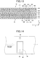
- the heat-flux sensor 40 and the heat-transfer element 50 are formed on one common substrate that includes the rear-surface-protective member 110, the insulating substrate 100, the front-surface-protective member 120, the rear-surface-protective member 210, the insulating substrate 200, and the front surface-protective member 220.
- the heat-flux sensor 40 in FIG. 13 corresponds to a cross section of a portion that differs from that in FIG. 4 , and the heat-flux sensor 40 is such that in a different cross section than that illustrated in FIG. 13 , the connecting patterns 122 are exposed by connecting holes (not illustrated in the figures) that are formed so as to penetrate through the heat-transfer element 50. Then, the heat-flux sensor 40 can be electrically connected with the control unit 60 via the connecting holes.
- the dimensions of the planar shape of the heat-flux sensor 40 and the dimensions of the planar shape of the heat-transfer element 50 are the same. However, even for the heat-flux sensor 40 and heat-transfer element 50 in such a state, when viewed from the layering direction (thickness direction Z) of the heat-flux sensor 40 and heat-transfer element 50, it can be said that the heat-transfer element 50 is positioned inside the heat-flux sensor 40.
- This kind of heat-flux sensor 40 and heat-transfer element 50 are integrated and manufactured by forming a laminate by layering in order the rear-surface-protective member 110 of the heat-flux sensor 40, the insulating substrate 100, the front-surface-protective member 120, the rear-surface-protective member 210 of the heat-transfer element 50, the insulating substrate 200, and the front-surface-protective member 220, and then applying pressure while heating the laminate.
- the heat-flux sensor 40 and heat-transfer element 50 are integrated into a single body. Therefore, when installing the heat-flux sensor 40 and heat-transfer element 50 on the pipe 10, it is possible to obtain the same effect as in the first embodiment while suppressing an occurrence of shifting of the position of the heat-flux sensor 40 and the heat-transfer element 50.
- a sixth embodiment of the present invention is explained.
- the present embodiment differs from the first embodiment in that the arrangement location of the first temperature sensor 20 is changed, however, the other parts are the same as those in the first embodiment, so an explanation of those parts is omitted here.
- the first temperature sensor 20 is arranged so as to be separated from the second temperature sensor 30 (heat-transfer element 50) in the circumferential direction of the pipe 10.
- FIG. 14 is a schematic plan view as seen from the outer-wall surface side of the pipe 10, and illustrates a state in which the insulating member 80 is omitted.
- the first temperature sensor 20 is arranged so as to be sufficiently separated from the second temperature sensor 30 (heat-transfer element 50) so that the temperature of the portion of the outer-wall surface of the pipe 10 that is not heated by the heat-transfer element 50 can be detected.
- the first temperature sensor 20 is separated in the circumferential direction of the pipe 10 from the heat-transfer element 50. Therefore, when a ring-shaped insulating member 80 is arranged so as to cover the first temperature sensor 20, second temperature sensor 30, heat-flux sensor 40, heat-transfer element 50 and pipe 10 in the circumferential direction, it is possible to shorten the length of the insulating member 80 in the direction of flow of the measurement medium. As a result, it is possible to reduce the amount used for the entire insulating member 80.
- the configuration of the heat-flux sensor 40 is not limited to that described above, and, for example, configuration of the heat-flux sensor 40 may be such that a thermopile is used.
- the heat-transfer element 50 may cool the outer-wall surface of the pipe 10.
- the second temperature sensor 30 may also be integrated with the heat-flux sensor 40.
- the second temperature sensor 30 may be integrated with the heat-flux sensor 40 by arranging the second temperature sensor 30 on the opposite side of the rear-surface-protective member 110 from the insulating substrate 100 side.
- the first temperature sensor 20 may be integrated with the heat-flux sensor 40 by arranging the first temperature sensor 20 on the opposite side of the rear-surface-protective member 110 from the insulating substrate 100 side.
- the fourth embodiment it is possible to integrate only the first temperature sensor 20 and the heat-flux sensor 40, and the second temperature sensor 20 does not need to be integrated with the heat-flux sensor 40.
- the second embodiment may be combined with the third and fourth embodiments, so that the second temperature sensor 30 is arranged outside of the area A.
- the second embodiment may be combined with the fifth and sixth embodiments so that the second temperature sensor 30 is arranged near the portion of the outer-wall surface of the pipe 10 that faces the heat-transfer element 50.
- the third and fourth embodiments may be combined with the sixth embodiment so that the heat-flux sensor 40, first temperature sensor 20 and second temperature sensor 30 are suitably integrated.
- the fifth embodiment may be combined with the sixth embodiment so that the heat-flux sensor 40 and the heat-transfer element 50 are integrated.
- the combinations of embodiments described above may also be combined with each other.
Landscapes
- Physics & Mathematics (AREA)
- General Physics & Mathematics (AREA)
- Fluid Mechanics (AREA)
- Engineering & Computer Science (AREA)
- Manufacturing & Machinery (AREA)
- Measuring Volume Flow (AREA)
- Measuring Temperature Or Quantity Of Heat (AREA)
Applications Claiming Priority (2)
| Application Number | Priority Date | Filing Date | Title |
|---|---|---|---|
| JP2015040555A JP6380168B2 (ja) | 2015-03-02 | 2015-03-02 | 熱式流量センサ |
| PCT/JP2016/053667 WO2016140019A1 (ja) | 2015-03-02 | 2016-02-08 | 熱式流量センサ |
Publications (2)
| Publication Number | Publication Date |
|---|---|
| EP3267162A1 true EP3267162A1 (de) | 2018-01-10 |
| EP3267162A4 EP3267162A4 (de) | 2018-04-11 |
Family
ID=56845008
Family Applications (1)
| Application Number | Title | Priority Date | Filing Date |
|---|---|---|---|
| EP16758714.6A Withdrawn EP3267162A4 (de) | 2015-03-02 | 2016-02-08 | Wärmeflussratenmesser |
Country Status (7)
| Country | Link |
|---|---|
| US (1) | US10458825B2 (de) |
| EP (1) | EP3267162A4 (de) |
| JP (1) | JP6380168B2 (de) |
| KR (1) | KR101902828B1 (de) |
| CN (1) | CN107430019B (de) |
| TW (1) | TWI606230B (de) |
| WO (1) | WO2016140019A1 (de) |
Families Citing this family (20)
| Publication number | Priority date | Publication date | Assignee | Title |
|---|---|---|---|---|
| GB2533936B (en) | 2015-01-07 | 2017-10-25 | Homeserve Plc | Flow detection device |
| GB201501935D0 (en) | 2015-02-05 | 2015-03-25 | Tooms Moore Consulting Ltd And Trow Consulting Ltd | Water flow analysis |
| EP3073235A1 (de) | 2015-03-26 | 2016-09-28 | ETH Zürich | Gel-basierende thermische sensoren |
| SE541080C2 (en) * | 2016-05-27 | 2019-04-02 | Jondetech Sensors Ab Publ Ab | Calibrating a heat flux sensor for measuring body temperature of an individual |
| DE102017120941B4 (de) * | 2017-09-11 | 2025-04-30 | Endress + Hauser Wetzer Gmbh + Co. Kg | Thermisches Durchflussmessgerät und Verfahren zum Betreiben eines thermischen Durchflussmessgeräts |
| CN108414036B (zh) * | 2018-03-19 | 2021-03-09 | 山东省科学院激光研究所 | 一种准分布式流速监测系统 |
| JP6985191B2 (ja) * | 2018-03-19 | 2021-12-22 | 株式会社Soken | 水素濃度検出装置 |
| US11255870B2 (en) | 2018-05-07 | 2022-02-22 | California Institute Of Technology | Gel and polymer based flow meters |
| US12152954B2 (en) | 2018-06-08 | 2024-11-26 | Orbis Intelligent Systems, Inc. | Detection device for a fluid conduit or fluid dispensing device |
| US12590824B2 (en) | 2018-06-08 | 2026-03-31 | Orbis Intelligent Systems, Inc. | Monitoring sites of a fluid delivery infrastructure |
| US11733115B2 (en) | 2018-06-08 | 2023-08-22 | Orbis Intelligent Systems, Inc. | Detection devices for determining one or more pipe conditions via at least one acoustic sensor and including connection features to connect with an insert |
| US11698314B2 (en) | 2018-06-08 | 2023-07-11 | Orbis Intelligent Systems, Inc. | Detection device for a fluid conduit or fluid dispensing device |
| US11150154B2 (en) | 2018-06-08 | 2021-10-19 | Orbis Intelligent Systems, Inc. | Pipe sensors |
| US11668613B2 (en) | 2019-05-06 | 2023-06-06 | California Institute Of Technology | ABA type block co-polymers for temperature sensing and flow meters |
| CA3142176C (en) | 2019-07-01 | 2023-02-07 | Thermasense Corp. | Apparatus, systems, and methods for non-invasive thermal interrogation |
| KR20210119909A (ko) | 2020-03-25 | 2021-10-06 | 삼성전자주식회사 | 열 또는 적외광 감지용 복합체 및 이를 포함하는 소자 |
| LU101845B1 (en) * | 2020-06-10 | 2021-12-10 | Rotarex S A | Pressure sensor formed by strain gauge on a deformable membrane of a fluid device |
| US11598689B1 (en) | 2021-10-24 | 2023-03-07 | Philip Becerra | Method of detecting and identifying underground leaking pipes |
| US12529617B1 (en) | 2021-10-24 | 2026-01-20 | Philip Becerra | Method of identifying and detecting a pipe containing an underground leak |
| US12442540B1 (en) | 2021-10-24 | 2025-10-14 | Philip Becerra | Method of detecting and identifying a location on a property corresponding to an underground cold water pipe leak |
Family Cites Families (19)
| Publication number | Priority date | Publication date | Assignee | Title |
|---|---|---|---|---|
| JPS5999466U (ja) * | 1983-10-03 | 1984-07-05 | 建設省建築研究所長 | 熱電堆 |
| JPH061185A (ja) | 1992-06-23 | 1994-01-11 | Toyoda Gosei Co Ltd | 自動車用ウエザストリップ |
| US5367905A (en) * | 1993-06-30 | 1994-11-29 | Kansas State University Research Foundation | Sap flow gauge |
| CA2309152A1 (en) * | 1997-12-02 | 1999-06-10 | Allan L. Smith | Apparatus and method for simultaneous measurement of mass and heat flow changes |
| US6595049B1 (en) * | 1999-06-18 | 2003-07-22 | Mks Instruments, Inc. | Thermal mass flow sensor with improved sensitivity and response time |
| JP2002002865A (ja) | 2000-06-16 | 2002-01-09 | Kenichiro Hirano | 粉ミルクの計量貯蔵容器 |
| JP2002286519A (ja) * | 2001-03-27 | 2002-10-03 | Tokyo Gas Co Ltd | 熱式流速センサ |
| JP2004069667A (ja) | 2002-06-12 | 2004-03-04 | Yokogawa Electric Corp | 液体用熱式質量流量計 |
| JP2005001373A (ja) | 2003-02-26 | 2005-01-06 | Mitsubishi Paper Mills Ltd | インクジェット記録材料 |
| US6883369B1 (en) * | 2004-05-06 | 2005-04-26 | Rosemount Aerospace Inc. | Sensor and method of measuring mass flow non-intrusively |
| JP5080020B2 (ja) * | 2006-04-13 | 2012-11-21 | 日立オートモティブシステムズ株式会社 | 熱式流量センサ |
| JP2012181090A (ja) | 2011-03-01 | 2012-09-20 | Nippon Soken Inc | 熱流束センサ |
| JP5769009B2 (ja) * | 2011-06-09 | 2015-08-26 | 江藤電気株式会社 | 熱流センサ及び熱流センサの製造方法 |
| JP2013002053A (ja) | 2011-06-13 | 2013-01-07 | Koshii Preserving:Kk | 簡易木製補強土壁およびその施工方法 |
| JP6110073B2 (ja) * | 2012-03-29 | 2017-04-05 | 高砂熱学工業株式会社 | 流量計測装置、及び流量計測方法 |
| JP5987811B2 (ja) * | 2013-06-04 | 2016-09-07 | 株式会社デンソー | 車両用の異常判定装置 |
| JP5761302B2 (ja) * | 2013-06-04 | 2015-08-12 | 株式会社デンソー | 車両用の快適温調制御装置 |
| US8820175B1 (en) * | 2013-09-10 | 2014-09-02 | King Fahd University Of Petroleum And Minerals | Sensor for two-phase flow measurements |
| JP2019035640A (ja) * | 2017-08-14 | 2019-03-07 | アズビル株式会社 | 熱式流量計 |
-
2015
- 2015-03-02 JP JP2015040555A patent/JP6380168B2/ja active Active
-
2016
- 2016-02-08 KR KR1020177024486A patent/KR101902828B1/ko not_active Expired - Fee Related
- 2016-02-08 US US15/554,112 patent/US10458825B2/en active Active
- 2016-02-08 WO PCT/JP2016/053667 patent/WO2016140019A1/ja not_active Ceased
- 2016-02-08 EP EP16758714.6A patent/EP3267162A4/de not_active Withdrawn
- 2016-02-08 CN CN201680013067.6A patent/CN107430019B/zh active Active
- 2016-03-01 TW TW105106135A patent/TWI606230B/zh not_active IP Right Cessation
Also Published As
| Publication number | Publication date |
|---|---|
| EP3267162A4 (de) | 2018-04-11 |
| JP6380168B2 (ja) | 2018-08-29 |
| CN107430019B (zh) | 2020-01-03 |
| US20180038722A1 (en) | 2018-02-08 |
| KR20170110664A (ko) | 2017-10-11 |
| TW201643383A (zh) | 2016-12-16 |
| JP2016161415A (ja) | 2016-09-05 |
| TWI606230B (zh) | 2017-11-21 |
| CN107430019A (zh) | 2017-12-01 |
| KR101902828B1 (ko) | 2018-10-01 |
| WO2016140019A1 (ja) | 2016-09-09 |
| US10458825B2 (en) | 2019-10-29 |
Similar Documents
| Publication | Publication Date | Title |
|---|---|---|
| US10458825B2 (en) | Thermal flow-rate sensor | |
| EP3348976B1 (de) | Mikrokanalwärmetauscher | |
| EP3348975B1 (de) | Wärmetauscher | |
| EP3304016B1 (de) | Befestigungselement mit eingebautem messfühler zur messung eines temperaturunterschieds | |
| CN104797941B (zh) | 热式流量测量设备 | |
| KR102012991B1 (ko) | 열류계들을 사용하여 핫 스팟들을 국부화하는 디바이스 | |
| JP6361723B2 (ja) | マイクロ流路熱交換器 | |
| US10957839B2 (en) | Heat flow sensor and method of manufacture thereof | |
| TWI624190B (zh) | Hot plate, manufacturing device of heat flux sensor using the same, manufacturing method of the hot plate, and manufacturing device of the same | |
| Cerimovic et al. | Calorimetric flow sensors based on thick-film printed thermopiles for air conditioning system monitoring | |
| JP2008002896A5 (de) | ||
| US11221261B2 (en) | Device for measuring heat transfer rate | |
| Maciejewska et al. | Heat transfer coefficient determination using the FEM with time-dependent Trefftz-type basis functions in subcooled flow boiling in a minichannel |
Legal Events
| Date | Code | Title | Description |
|---|---|---|---|
| STAA | Information on the status of an ep patent application or granted ep patent |
Free format text: STATUS: THE INTERNATIONAL PUBLICATION HAS BEEN MADE |
|
| PUAI | Public reference made under article 153(3) epc to a published international application that has entered the european phase |
Free format text: ORIGINAL CODE: 0009012 |
|
| STAA | Information on the status of an ep patent application or granted ep patent |
Free format text: STATUS: REQUEST FOR EXAMINATION WAS MADE |
|
| 17P | Request for examination filed |
Effective date: 20170831 |
|
| AK | Designated contracting states |
Kind code of ref document: A1 Designated state(s): AL AT BE BG CH CY CZ DE DK EE ES FI FR GB GR HR HU IE IS IT LI LT LU LV MC MK MT NL NO PL PT RO RS SE SI SK SM TR |
|
| AX | Request for extension of the european patent |
Extension state: BA ME |
|
| STAA | Information on the status of an ep patent application or granted ep patent |
Free format text: STATUS: EXAMINATION IS IN PROGRESS |
|
| A4 | Supplementary search report drawn up and despatched |
Effective date: 20180308 |
|
| RIC1 | Information provided on ipc code assigned before grant |
Ipc: G01F 1/688 20060101AFI20180303BHEP Ipc: G01F 1/684 20060101ALI20180303BHEP |
|
| 17Q | First examination report despatched |
Effective date: 20180320 |
|
| DAV | Request for validation of the european patent (deleted) | ||
| DAX | Request for extension of the european patent (deleted) | ||
| GRAP | Despatch of communication of intention to grant a patent |
Free format text: ORIGINAL CODE: EPIDOSNIGR1 |
|
| STAA | Information on the status of an ep patent application or granted ep patent |
Free format text: STATUS: GRANT OF PATENT IS INTENDED |
|
| INTG | Intention to grant announced |
Effective date: 20190531 |
|
| STAA | Information on the status of an ep patent application or granted ep patent |
Free format text: STATUS: THE APPLICATION IS DEEMED TO BE WITHDRAWN |
|
| 18D | Application deemed to be withdrawn |
Effective date: 20191011 |