EP3267284A1 - Ensemble couvercle avant de terminal et terminal - Google Patents
Ensemble couvercle avant de terminal et terminal Download PDFInfo
- Publication number
- EP3267284A1 EP3267284A1 EP16840595.9A EP16840595A EP3267284A1 EP 3267284 A1 EP3267284 A1 EP 3267284A1 EP 16840595 A EP16840595 A EP 16840595A EP 3267284 A1 EP3267284 A1 EP 3267284A1
- Authority
- EP
- European Patent Office
- Prior art keywords
- wall
- step portion
- face
- lateral face
- waterproof glue
- Prior art date
- Legal status (The legal status is an assumption and is not a legal conclusion. Google has not performed a legal analysis and makes no representation as to the accuracy of the status listed.)
- Ceased
Links
Images


Classifications
-
- G—PHYSICS
- G06—COMPUTING OR CALCULATING; COUNTING
- G06F—ELECTRIC DIGITAL DATA PROCESSING
- G06F1/00—Details not covered by groups G06F3/00 - G06F13/00 and G06F21/00
- G06F1/16—Constructional details or arrangements
- G06F1/1613—Constructional details or arrangements for portable computers
- G06F1/1633—Constructional details or arrangements of portable computers not specific to the type of enclosures covered by groups G06F1/1615 - G06F1/1626
- G06F1/1656—Details related to functional adaptations of the enclosure, e.g. to provide protection against EMI, shock, water, or to host detachable peripherals like a mouse or removable expansions units like PCMCIA cards, or to provide access to internal components for maintenance or to removable storage supports like CDs or DVDs, or to mechanically mount accessories
-
- G—PHYSICS
- G06—COMPUTING OR CALCULATING; COUNTING
- G06F—ELECTRIC DIGITAL DATA PROCESSING
- G06F1/00—Details not covered by groups G06F3/00 - G06F13/00 and G06F21/00
- G06F1/16—Constructional details or arrangements
-
- H—ELECTRICITY
- H04—ELECTRIC COMMUNICATION TECHNIQUE
- H04M—TELEPHONIC COMMUNICATION
- H04M1/00—Substation equipment, e.g. for use by subscribers
- H04M1/02—Constructional features of telephone sets
Definitions
- the present disclosure relates to electronic communication technology, and more particularly, to a front cover assembly and a terminal.
- smart terminals With rapid development of technology, smart terminals are widely used.
- the smart terminals not only provide a mobile communication function for users, but also provide the users with various application programs. This brings the users great convenience.
- these products do not have good waterproof and dustproof capabilities.
- the smart terminals may be damaged and cause data loss once the smart terminals fall into water, are splattered with a conducting liquid such as water, or are exposed to water vapor or a high-humidity environment.
- most smart terminal products have a waterproof structure. If a waterproof and dustproof device is mounted on the smart terminal products, external appearance and aesthetics of the smart terminal products will be affected as well as overall thickness of the smart terminal products will increase. This is not good for user experience.
- the objective of the present disclosure is to provide a front cover assembly and a terminal to carry out better waterproofing as well as a reduction of black periphery of the front cover assembly.
- a front cover assembly including a frame, a cover glass, and a waterproof glue.
- the frame includes a receiving cavity, which includes a first wall and a second wall connecting to the first wall.
- the cover glass is partially received in the frame, and includes an upper face and a first lateral face surrounding the upper face.
- the upper face is a light exiting face.
- the first lateral face has a step portion disposed at a peripheral area thereof.
- the step portion surrounds the first lateral face, and includes a bottom face and a lateral face.
- a first gap is defined between the lateral face of the step portion and the first wall and a second gap is defined between the bottom face of the step portion and the second wall.
- the waterproof glue is disposed on the bottom face of the step portion, the first wall, and the second wall and is configured to fill the first gap and the second gap.
- the first wall is a top wall of the receiving cavity
- the second wall surrounds a second lateral face of the first wall
- a portion connecting between the first wall and the second wall is a round corner portion
- the first lateral face includes a first portion and a second portion, the first portion has the step portion deployed thereon, the second portion is connected to the upper face, and the second portion is a curved face.
- the waterproof glue and the lateral face of the step portion engage each other by interference fit.
- An amount of interference between the waterproof glue and the lateral face of the step portion ranges from 0.03mm to 0.10mm.
- the waterproof glue forms a glued path along an extended direction of the step portion.
- the frame has a first degree of softness
- the waterproof glue has a second degree of softness
- the second degree of softness is less than the first degree of softness
- the present disclosure further provides a terminal, which includes a rear cover, a control assembly, and a front cover assembly.
- the rear cover includes a receiving space.
- the front cover assembly and the control assembly are received in the receiving space.
- the control assembly is connected to the front cover assembly and is configured to control the front cover assembly to carry out a display function.
- the frame includes a receiving cavity, which includes a first wall and a second wall connecting to the first wall.
- the cover glass is partially received in the frame, and includes an upper face and a first lateral face surrounding the upper face.
- the upper face is a light exiting face.
- the first lateral face has a step portion disposed at a peripheral area thereof. The step portion surrounds the first lateral face, and includes a bottom face and a lateral face.
- a first gap is defined between the lateral face of the step portion and the first wall and a second gap is defined between the bottom face of the step portion and the second wall.
- the waterproof glue is disposed on the bottom face of the step portion, the first wall, and the second wall and is configured to fill the first gap and the second gap.
- the first wall is a top wall of the receiving cavity
- the second wall surrounds a second lateral face of the first wall
- a portion connecting between the first wall and the second wall is a round corner portion
- the first lateral face includes a first portion and a second portion, the first portion has the step portion deployed thereon, the second portion is connected to the upper face, and the second portion is a curved face.
- the waterproof glue and the lateral face of the step portion engage each other by interference fit.
- An amount of interference between the waterproof glue and the lateral face of the step portion ranges from 0.03mm to 0.10mm.
- the waterproof glue forms a glued path along an extended direction of the step portion.
- the frame has a first degree of softness
- the waterproof glue has a second degree of softness
- the second degree of softness is less than the first degree of softness
- the present disclosure further provides a front cover assembly, which includes a frame, a cover glass, and a waterproof glue.
- the frame includes a receiving cavity, which includes a first wall and a second wall connecting to the first wall.
- the cover glass is partially received in the frame, and includes a first lateral face.
- the first lateral face has a step portion disposed at a peripheral area thereof.
- the step portion surrounds the first lateral face.
- the waterproof glue is disposed on the step portion and covers the step portion to fill a gap between the cover glass and the frame.
- the first wall is a top wall of the receiving cavity
- the second wall surrounds a second lateral face of the first wall
- a portion connecting between the first wall and the second wall is a round corner portion
- the first lateral face includes a first portion and a second portion, the first portion has the step portion deployed thereon, the second portion is connected to the upper face, and the second portion is a curved face.
- the waterproof glue and the lateral face of the step portion engage each other by interference fit.
- An amount of interference between the waterproof glue and the lateral face of the step portion ranges from 0.03mm to 0.10mm.
- the waterproof glue forms a glued path along an extended direction of the step portion.
- the step portion is deployed at the peripheral area of the first lateral face of the cover glass and surrounds the first lateral face.
- the step portion includes the lateral face and the bottom face.
- a first gap is defined between the lateral face of the step portion and the first wall of the receiving cavity.
- a second gap is defined between the bottom face of the step portion and the second wall of the receiving cavity.
- the waterproof glue is disposed on the bottom face of the step portion, the first wall, and the second wall. In such a way, the waterproof glue can fill the first gap and the second gap. This prevents the water coming from outside, from permeating into the first gap and the second gap via the cover glass, causing the internal electric circuits of the terminal to contact with the water. In addition, this can further prevent the dust coming from outside, from falling or entering a space between the cover glass and a housing, thereby achieving waterproofing and dustproofing effectiveness.
- the present disclosure provides a terminal.
- the terminal includes a rear cover (not shown) and a front cover assembly 100.
- the rear cover has an receiving space (not shown).
- the front cover assembly 100 is fastened and received in the receiving space.
- the terminal may be, but is not limited to, a mobile communication device such as a cell phone, a personal digital assistant (PDA), a tablet computer, and so on.
- a mobile communication device such as a cell phone, a personal digital assistant (PDA), a tablet computer, and so on.
- PDA personal digital assistant
- the terminal is illustrated by a cell phone as an example.
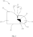
- the front cover assembly 100 includes a frame 10, a cover glass 20, and a waterproof glue 30.
- the frame 10 has a receiving cavity 11.
- the receiving cavity includes a first wall and a second wall connecting with the first wall.
- the cover glass 20 is partially received in the receiving cavity 11 (and/or the frame 10).
- the cover glass 20 includes an upper face and a first lateral face 21 surrounding the upper face.
- the upper face is a light exiting face.
- the first lateral face 21 has a step portion 211 disposed at a peripheral area of the first lateral face 21.
- the step portion 211 is configured to surround the first lateral face 21.
- the step portion 211 includes a bottom face 211 a and a lateral face 211b.
- a first gap 212 is defined between the lateral face 211b and the first wall 111.
- a second gap 213 is defined between the bottom face 211 a and the second wall 112.
- the waterproof glue 30 is applied on the bottom face 211a, the first wall 111
- the step portion 211 is deployed at the peripheral area of the first lateral face 21 of the cover glass 20.
- the cover glass 20 is partially received in the receiving cavity 11 of the frame 10.
- a gap (including the first gap 212 and the second gap 213) is defined between the first lateral face 21 of the cover glass 20 and the frame 10.
- the waterproof glue 30 is applied on the step portion 211 and covers the step portion 211. In such a way, the waterproof glue 30 can fill the gap between the cover glass 20 and the frame 10. This prevents water coming from outside of the cover glass 20 or the frame 10, from permeating into the receiving cavity 11 via the cover glass 20, or prevent the dust coming from outside of the cover glass 20, from falling into the receiving cavity 11, thereby achieving waterproofing and dustproofing effectiveness.
- the step portion 211 deployed at the first lateral face 21 of the cover glass 20 is configured to dispose the waterproof glue 30. This reduces the space of the receiving cavity 11 and the cover glass 20 occupied by the waterproof glue 30, and at the same time waterproofing is assured. In this way, overall thickness of the waterproof device 100 is reduced.
- the frame 10 is shaped as a rectangle.
- Material of the frame 10 is a rigid rubber.
- the frame 10 has a first degree of softness, that is, the rigid rubber has the first degree of softness.
- the four corners of the frame 10 are round corner portions. In this way, it is convenient to grip for a user with greater comfort, thereby improving user experience.
- the thickness of the frame 10 i.e., the thickness taken along a direction perpendicular to a plane that the frame 10 is located on
- the thickness of the frame 10 is less than that of the cover glass 20. In this way, the cover glass 20 is partially received in the frame 10 as well as the overall thickness of the front cover assembly 100 is reduced.
- the frame 10 can be disposed and adjusted according to a shape of the terminal in other embodiments.
- the waterproof glue 30 is coated around the frame 10, thereby preventing water coming from outside of the frame 10, from permeating into an inner side of the frame 10 and thus carrying out waterproofing.
- the receiving cavity 11 includes a first wall 111 and a second wall 112 connecting with the first wall 111.
- the cross-section of the receiving cavity 11 is shaped as sawtooth.
- the first wall 111 is a top wall of the receiving cavity 111.
- the second wall 112 is a second lateral face that surrounds the first wall 111.
- a round corner portion is disposed between the first wall 111 and the second wall 112. That is, a portion connected between the first wall 111 and the second wall 112 is a round corner portion.
- the cover glass 20 is fastened inside the receiving cavity 11.
- the cover glass 20 is a rectangular plate structure.
- the corners of the cover glass 20 are round corner portions.
- the cover glass 20 is a piece of transparent glass.
- the cover glass 20 is a rectangular plate member.
- the cover glass 20 can increase light transmittance of a display screen and enhance visual effects of the terminal.
- the cover glass 20 is a transparent rigid plate member, thereby having excellent protective effects on internal components of the terminal and carrying out excellent light transmittance.
- the thickness of the cover glass 20 ranges from 0.3mm to 2.0mm, for example, 0.3mm, 0.4mm, 0.5mm, 0.6mm, 0.7mm, 0.8mm, 0.9mm, 1mm, 1.1mm, 1.2mm, 1.3mm, 1.4mm, 1.5mm, 1.6mm, 1.7mm, 1.8mm, 1.9mm, and 2mm.
- the cover glass 20 can make the terminal become thinner and meet the requirements of thickness of the terminal in a further step, as well as assuring sufficient strength of the terminal.
- the cover glass 20 includes the upper face 22 and a lower face 23 opposite to each other.
- the upper face 22 is a light exiting face and the lower face 23 is a light entering face.
- the upper face 22 is utilized to emit light rays.
- a light-blocking region (not shown) is disposed on the lower face 23. The light-blocking region is configured to cover the electronic wires connected between the cover glass 20 and other components, thereby assuring not to affect the external appearance and aesthetics of the front cover assembly 100.
- the front cover assembly 100 further includes a display screen (not shown).
- the display screen includes a display surface attached to the lower face 23 to show the displayed images on the upper face 22.
- the display surface of the display screen is adhered to the lower face 23 via adhesive, thereby assuring a tight connection between the display screen and the cover glass 20.
- the display screen can also be connected to the cover glass 20 by a PET (polyethylene terephthalate) adhesive strips.
- the first lateral face 21 includes a first portion 214 and a second portion 215.
- the first portion 214 has the step portion 211 deployed thereon.
- the second portion 215 is connected to the upper face 22.
- a round corner portion is smoothly disposed between the first portion 214 and the second portion 215.
- the second portion 215 is a curved face. In such a way, it can refract the light from the light-blocking region on the upper face 22.
- the user can perceive a narrow-bezel visual effect in using the front cover assembly 100. The user experience is further improved.
- the step portion 211 can be formed by CNC (computer numerical control) machining. In this way, the formed step portion 211 can get better precision.
- the step portion 211 is a L-shaped step portion, which can accommodate the waterproof glue 30 completely.
- the step portion 211 can be formed with other shapes such as a stair-step portion shape in other embodiments.
- a lateral face 211b of the step portion 211 is perpendicular to a bottom face 211 a of the step portion 211.
- the first gap 212 is defined between the lateral face 211b of the step portion 211 and the first wall 111 and the second gap 213 is defined between the bottom face 211a of the step portion 211 and the second wall 112.
- the waterproof glue 30 is applied to the lateral face 211b and the bottom face 211a of the step portion 211 and is abutted between the first wall 111 and the second wall 112.
- an amount of interference of the waterproof glue 30 ranges from 0.03mm to 0.1mm, for example, 0.03mm, 0.035mm, 0.04mm, 0.045mm, 0.05mm, 0.055mm, 0.06mm, 0.065mm, 0.07mm, 0.075mm, 0.08mm, 0.085mm, 0.09mm, 0.095mm, and 0.1mm.
- the waterproof glue 30 is a soft glue.
- the waterproof glue 30 is applied to the bottom face 211a and the lateral face 211b of the step portion 211 by a spray machine (not shown), and forms a glued path along an extended direction of the step portion 211. In this way, this prevents the liquid or dust coming from outside of the cover glass 20, from entering the first gap 212 and the second gap 213 via the cover glass 20. Meanwhile, since the waterproof glue 30 forms the glued path along the extended direction of the step portion 211, this can prevent the glue from breaking off or hanging over, thereby further assuring waterproofing.
- the waterproof glue 30 has a second degree of softness, that is, the soft glue has the second degree of softness. The second degree of softness is less than the first degree of softness.
- the waterproof glue 30 adopts the soft glue, thereby carrying out adhesion in a quick manner, assuring tightness of the adhesion, and further assure waterproofing.
- the waterproof glue 30 is a soft glue and the frame 10 adopts a rigid rubber, the combination of the soft glue and the rigid rubber makes the waterproof glue 30 and the frame 10 tightly adhered to each other, thereby further assuring waterproofing.
- the waterproof glue 30 forms the glued path along the extended direction of the step portion 211.
- the cover glass 20 and the receiving cavity 11 are attached together, and meanwhile the waterproof glue 30 can fill the gaps between the cover glass 20 and the receiving cavity 11 to prevent water or dust from entering via the gaps, causing a short in the internal circuits or falling dust that leads to an inconvenience to clean way.
- the cover glass 30 forms the glued path along the bottom face 211a of the step portion 211, this acts as a buffer of the cover glass 20 and prevents the cover glass 20 from being damaged by an external impact or squeeze.
- the height of the waterproof glue 30 ranges from 0.2mm to 0.3mm, for example, 0.2mm, 0.21mm, 0.22mm, 0.23mm, 0.24mm, 0.25mm, 0.26mm, 0.27mm, 0.28mm, 0.29mm, and 0.3mm. That is, the height of the glued path ranges from 0.2mm to 0.3mm. In such a way, it is assured that the waterproof glue 30 and the cover glass 20 engage each other by interference fit, the requirement of the interference is met, and the buffer function is carried out. In can be understood that the height of the waterproof glue 30 can be adjusted based on the actual situation (e.g., ranging from 0.3mm to 0.4mm) in other embodiments.
- the waterproof glue 30 is applied to the bottom face 211a and the lateral face 211b of the step portion 211 by the spray machine. Meanwhile, the speed and frequency in spraying the waterproof glue 30 using the spray machine can be adjusted so as to control the height of the glued path formed by the waterproof glue 30 on the bottom face 211a of the step portion 211.
- the cover glass 20 and the waterproof glue 30 are prepressed using a pressure pre-charging or maintaining device to assure that a predetermined amount of interference exists between the cover glass 20 and the waterproof glue 30, thereby carrying out better waterproofing between the cover glass 20 and the cover glass 30.
- the waterproof glue 30 occupies a small space.
- the material of the waterproof glue 30 is a soft glue and the frame 10 is a rigid rubber.
- the waterproof glue 30 is the soft glue, which does not occupy extra space of the cover glass 20 and the frame 10. It is beneficial to improve structure compactness of the front cover assembly 100.
- the terminal further includes a control assembly (not shown).
- the control assembly is connected to the rear cover.
- the control assembly is configured to control the front cover assembly 100 to carry out a display function.
- the control assembly controls the display screen to display images.
- the display screen is disposed below the cover glass 20 and overlaps with it so as to transmit the images via the cover glass 20.
- the step portion 211 is deployed at the peripheral area of the first lateral face 21 of the cover glass 20 and surrounds the first lateral face 21.
- the step portion 211b includes the lateral face 211b and the bottom face 211a.
- a first gap 212 is defined between the lateral face 211b of the step portion 211 and the first wall 111 of the receiving cavity 11.
- a second gap 213 is defined between the bottom face 211a of the step portion 211 and the second wall 112 of the receiving cavity 11.
- the waterproof glue 30 is disposed on the bottom face 211a of the step portion 211, the first wall 111, and the second wall 112. In such a way, the waterproof glue 30 can fill the first gap 212 and the second gap 213.
Landscapes
- Engineering & Computer Science (AREA)
- Theoretical Computer Science (AREA)
- Computer Hardware Design (AREA)
- General Engineering & Computer Science (AREA)
- Human Computer Interaction (AREA)
- Physics & Mathematics (AREA)
- General Physics & Mathematics (AREA)
- Signal Processing (AREA)
- Telephone Set Structure (AREA)
- Casings For Electric Apparatus (AREA)
- Devices For Indicating Variable Information By Combining Individual Elements (AREA)
Applications Claiming Priority (2)
| Application Number | Priority Date | Filing Date | Title |
|---|---|---|---|
| CN201510552123.0A CN105116967B (zh) | 2015-08-31 | 2015-08-31 | 终端前盖组件及终端 |
| PCT/CN2016/081496 WO2017036166A1 (fr) | 2015-08-31 | 2016-05-10 | Ensemble couvercle avant de terminal et terminal |
Publications (2)
| Publication Number | Publication Date |
|---|---|
| EP3267284A1 true EP3267284A1 (fr) | 2018-01-10 |
| EP3267284A4 EP3267284A4 (fr) | 2018-03-28 |
Family
ID=54664985
Family Applications (1)
| Application Number | Title | Priority Date | Filing Date |
|---|---|---|---|
| EP16840595.9A Ceased EP3267284A4 (fr) | 2015-08-31 | 2016-05-10 | Ensemble couvercle avant de terminal et terminal |
Country Status (4)
| Country | Link |
|---|---|
| US (2) | US10198042B2 (fr) |
| EP (1) | EP3267284A4 (fr) |
| CN (1) | CN105116967B (fr) |
| WO (1) | WO2017036166A1 (fr) |
Cited By (1)
| Publication number | Priority date | Publication date | Assignee | Title |
|---|---|---|---|---|
| EP3554055A4 (fr) * | 2016-12-26 | 2019-10-16 | Huawei Technologies Co., Ltd. | Ensemble coque, terminal mobile et procédé d'assemblage d'ensemble coque |
Families Citing this family (15)
| Publication number | Priority date | Publication date | Assignee | Title |
|---|---|---|---|---|
| CN105116967B (zh) | 2015-08-31 | 2017-09-26 | 广东欧珀移动通信有限公司 | 终端前盖组件及终端 |
| KR102606498B1 (ko) * | 2016-08-29 | 2023-11-27 | 엘지전자 주식회사 | 이동 단말기 |
| CN106843390B (zh) * | 2017-01-09 | 2020-02-04 | Oppo广东移动通信有限公司 | 显示屏组件、电子装置及显示屏组件的制作方法 |
| CN107861566B (zh) * | 2017-10-31 | 2022-09-13 | 维沃移动通信有限公司 | 一种移动终端 |
| CN108881559B (zh) * | 2018-08-10 | 2021-04-23 | 维沃移动通信有限公司 | 一种移动终端 |
| US10568218B1 (en) * | 2018-11-27 | 2020-02-18 | Wuhan China Star Optoelectronics Semiconductor Display Technology Co., Ltd. | Narrow bezel display |
| CN113489814B (zh) | 2018-12-10 | 2024-01-05 | Oppo广东移动通信有限公司 | 电子设备 |
| CN114422630A (zh) | 2018-12-10 | 2022-04-29 | Oppo广东移动通信有限公司 | 电子设备 |
| CN111625050A (zh) | 2019-02-28 | 2020-09-04 | Oppo广东移动通信有限公司 | 电子设备 |
| CN110225163B (zh) * | 2019-06-26 | 2021-03-12 | Oppo广东移动通信有限公司 | 电子设备 |
| CN115705789A (zh) * | 2021-08-16 | 2023-02-17 | 群创光电股份有限公司 | 可挠式显示装置 |
| CN113744645B (zh) * | 2021-08-31 | 2022-07-05 | 惠科股份有限公司 | 显示设备 |
| US12418997B2 (en) * | 2022-05-12 | 2025-09-16 | Chengdu Boe Optoelectronics Technology Co., Ltd. | Display device |
| CN115097904A (zh) * | 2022-07-25 | 2022-09-23 | 荣耀终端有限公司 | 一种电子设备 |
| CN116149432B (zh) * | 2023-04-19 | 2023-10-03 | 荣耀终端有限公司 | 翻盖式笔记本电脑 |
Family Cites Families (33)
| Publication number | Priority date | Publication date | Assignee | Title |
|---|---|---|---|---|
| WO2004068189A2 (fr) * | 2003-01-27 | 2004-08-12 | David Stark | Ensembles fenetres hermetiques et cadres associes |
| US20040222965A1 (en) * | 2003-05-05 | 2004-11-11 | Riccomini Roy J. | System and method for generating an analog signal in a hand-held computing device |
| US7210963B2 (en) * | 2004-10-12 | 2007-05-01 | Qualcomm Incorporated | Devices and methods for connecting housings |
| JP4483833B2 (ja) * | 2005-09-22 | 2010-06-16 | エプソンイメージングデバイス株式会社 | 電気光学装置、電子機器、保護部材、保護部材の製造方法 |
| US8578081B1 (en) * | 2007-07-25 | 2013-11-05 | Robert Louis Fils | Docking station for an electronic device |
| US8218306B2 (en) * | 2007-09-04 | 2012-07-10 | Apple Inc. | Assembly of a handheld electronic device |
| TWI389627B (zh) * | 2009-11-20 | 2013-03-11 | Chimei Innolux Corp | 電路板固定結構及應用該結構的液晶顯示裝置與電子裝置 |
| US8305744B2 (en) * | 2010-05-14 | 2012-11-06 | Apple Inc. | Shock mounting cover glass in consumer electronics devices |
| KR101230774B1 (ko) * | 2010-09-03 | 2013-02-06 | 알프스 덴키 가부시키가이샤 | 유리 복합체, 유리 복합체를 사용한 전자 기기, 및 입력 장치, 그리고 유리 복합체의 제조 방법 |
| EP2658993B1 (fr) * | 2010-12-31 | 2014-10-01 | Alphacore Pharma LLC | Détection d'activité lcat |
| KR101204675B1 (ko) | 2011-02-15 | 2012-11-26 | 에스케이하이닉스 주식회사 | 커패시터 및 금속 콘택을 포함하는 반도체 소자 및 형성 방법 |
| JP6050962B2 (ja) * | 2011-12-08 | 2016-12-21 | 吉田テクノワークス株式会社 | ガラス一体型成形品の製造方法、ガラス一体型成形品 |
| JP2013187456A (ja) * | 2012-03-09 | 2013-09-19 | Toshiba Corp | 防水構造 |
| JP2013235145A (ja) * | 2012-05-09 | 2013-11-21 | Japan Display Inc | 表示装置 |
| US9047044B2 (en) * | 2012-10-19 | 2015-06-02 | Apple Inc. | Trimless glass enclosure interface |
| US20140239781A1 (en) * | 2013-02-25 | 2014-08-28 | Motorola Mobility Llc | Electronic Device Having a Display and Method of Manufacture |
| KR20150000100A (ko) * | 2013-06-24 | 2015-01-02 | 삼성디스플레이 주식회사 | 평판 디스플레이 장치 및 그 제조 방법 |
| US9462099B2 (en) * | 2013-08-30 | 2016-10-04 | Wimo Labs LLC | Mobile device case |
| KR101543580B1 (ko) * | 2013-11-06 | 2015-08-11 | (주)코텍 | 디스플레이장치 |
| US9261915B2 (en) * | 2013-12-21 | 2016-02-16 | Kyocera Corporation | Electronic apparatus, light-transmissive cover plate, and portable device |
| CN203615200U (zh) * | 2013-12-27 | 2014-05-28 | 上海天马微电子有限公司 | 背光模组及其显示装置 |
| CN203748139U (zh) * | 2013-12-30 | 2014-07-30 | 惠州比亚迪电子有限公司 | 一种电子产品 |
| JP6370556B2 (ja) * | 2014-01-29 | 2018-08-08 | 京セラ株式会社 | 電子機器 |
| US9872407B2 (en) * | 2014-07-29 | 2018-01-16 | Sharp Kabushiki Kaisha | Electronic device |
| RU2017103517A (ru) * | 2014-07-31 | 2018-08-02 | Юйлун Компьютер Телекоммьюникейшн Сайнтифик (Шэньчжэнь) Ко., Лтд. | Устройство отображения и терминал |
| JP2016109761A (ja) * | 2014-12-03 | 2016-06-20 | セイコーエプソン株式会社 | 光学部品および時計 |
| CN108415510B (zh) * | 2014-12-09 | 2020-12-08 | Oppo广东移动通信有限公司 | 终端 |
| CN104536518B (zh) * | 2014-12-09 | 2018-01-23 | 广东欧珀移动通信有限公司 | 终端前盖、终端前盖组件及终端 |
| KR102269507B1 (ko) * | 2015-02-02 | 2021-06-25 | 삼성디스플레이 주식회사 | 표시장치 |
| CN104866018B (zh) * | 2015-04-20 | 2019-03-05 | Oppo广东移动通信有限公司 | 终端前盖及终端 |
| CN105187583B (zh) * | 2015-08-31 | 2018-07-06 | 广东欧珀移动通信有限公司 | 终端前盖组件及终端 |
| CN105116967B (zh) * | 2015-08-31 | 2017-09-26 | 广东欧珀移动通信有限公司 | 终端前盖组件及终端 |
| CN205005392U (zh) * | 2015-08-31 | 2016-01-27 | 广东欧珀移动通信有限公司 | 终端前盖组件及终端 |
-
2015
- 2015-08-31 CN CN201510552123.0A patent/CN105116967B/zh not_active Expired - Fee Related
-
2016
- 2016-05-10 WO PCT/CN2016/081496 patent/WO2017036166A1/fr not_active Ceased
- 2016-05-10 EP EP16840595.9A patent/EP3267284A4/fr not_active Ceased
-
2017
- 2017-09-24 US US15/713,663 patent/US10198042B2/en active Active
-
2019
- 2019-01-22 US US16/253,686 patent/US10712782B2/en not_active Expired - Fee Related
Cited By (1)
| Publication number | Priority date | Publication date | Assignee | Title |
|---|---|---|---|---|
| EP3554055A4 (fr) * | 2016-12-26 | 2019-10-16 | Huawei Technologies Co., Ltd. | Ensemble coque, terminal mobile et procédé d'assemblage d'ensemble coque |
Also Published As
| Publication number | Publication date |
|---|---|
| WO2017036166A1 (fr) | 2017-03-09 |
| US10712782B2 (en) | 2020-07-14 |
| CN105116967B (zh) | 2017-09-26 |
| US20180011519A1 (en) | 2018-01-11 |
| EP3267284A4 (fr) | 2018-03-28 |
| CN105116967A (zh) | 2015-12-02 |
| US20190155340A1 (en) | 2019-05-23 |
| US10198042B2 (en) | 2019-02-05 |
Similar Documents
| Publication | Publication Date | Title |
|---|---|---|
| EP3267284A1 (fr) | Ensemble couvercle avant de terminal et terminal | |
| CN105120022B (zh) | 壳体组件及移动终端 | |
| CN105045347B (zh) | 终端前盖组件及移动终端 | |
| CN107580090B (zh) | 终端前盖组件及终端 | |
| CN105208150B (zh) | 壳体组件及移动终端 | |
| CN105263281B (zh) | 壳体组件及移动终端 | |
| CN105187583B (zh) | 终端前盖组件及终端 | |
| EP3176671B1 (fr) | Ensemble écran d'affichage et terminal | |
| CN105116966A (zh) | 终端前盖组件及终端 | |
| CN105120624B (zh) | 终端前盖组件及移动终端 | |
| CN104866021B (zh) | 显示屏组件及终端 | |
| CN105120023B (zh) | 壳体组件及移动终端 | |
| CN105120623B (zh) | 终端前盖组件及移动终端 | |
| CN105120024B (zh) | 壳体组件及移动终端 | |
| CN104866018A (zh) | 终端前盖及终端 | |
| CN205005393U (zh) | 终端前盖组件及移动终端 | |
| CN104866017A (zh) | 终端前盖及终端 | |
| CN204883473U (zh) | 显示屏组件及终端 | |
| CN108733146B (zh) | 移动终端 | |
| CN101866589B (zh) | 一种lcd屏防尘装置及移动终端 | |
| CN205039863U (zh) | 壳体组件及移动终端 | |
| CN205005392U (zh) | 终端前盖组件及终端 | |
| CN210609267U (zh) | 移动终端 | |
| CN108664081B (zh) | 指纹识别装置及终端设备 | |
| CN107861566B (zh) | 一种移动终端 |
Legal Events
| Date | Code | Title | Description |
|---|---|---|---|
| STAA | Information on the status of an ep patent application or granted ep patent |
Free format text: STATUS: THE INTERNATIONAL PUBLICATION HAS BEEN MADE |
|
| PUAI | Public reference made under article 153(3) epc to a published international application that has entered the european phase |
Free format text: ORIGINAL CODE: 0009012 |
|
| STAA | Information on the status of an ep patent application or granted ep patent |
Free format text: STATUS: REQUEST FOR EXAMINATION WAS MADE |
|
| 17P | Request for examination filed |
Effective date: 20171006 |
|
| AK | Designated contracting states |
Kind code of ref document: A1 Designated state(s): AL AT BE BG CH CY CZ DE DK EE ES FI FR GB GR HR HU IE IS IT LI LT LU LV MC MK MT NL NO PL PT RO RS SE SI SK SM TR |
|
| AX | Request for extension of the european patent |
Extension state: BA ME |
|
| A4 | Supplementary search report drawn up and despatched |
Effective date: 20180227 |
|
| RIC1 | Information provided on ipc code assigned before grant |
Ipc: G06F 1/16 20060101AFI20180221BHEP Ipc: H04M 1/02 20060101ALI20180221BHEP |
|
| DAV | Request for validation of the european patent (deleted) | ||
| DAX | Request for extension of the european patent (deleted) | ||
| RAP1 | Party data changed (applicant data changed or rights of an application transferred) |
Owner name: GUANGDONG OPPO MOBILE TELECOMMUNICATIONS CORP., LT |
|
| STAA | Information on the status of an ep patent application or granted ep patent |
Free format text: STATUS: EXAMINATION IS IN PROGRESS |
|
| 17Q | First examination report despatched |
Effective date: 20200907 |
|
| REG | Reference to a national code |
Ref country code: DE Ref legal event code: R003 |
|
| STAA | Information on the status of an ep patent application or granted ep patent |
Free format text: STATUS: THE APPLICATION HAS BEEN REFUSED |
|
| 18R | Application refused |
Effective date: 20230610 |