EP3267341B1 - Procédé et dispositif d'estimation de contrainte résiduelle - Google Patents
Procédé et dispositif d'estimation de contrainte résiduelle Download PDFInfo
- Publication number
- EP3267341B1 EP3267341B1 EP16758788.0A EP16758788A EP3267341B1 EP 3267341 B1 EP3267341 B1 EP 3267341B1 EP 16758788 A EP16758788 A EP 16758788A EP 3267341 B1 EP3267341 B1 EP 3267341B1
- Authority
- EP
- European Patent Office
- Prior art keywords
- residual stress
- plastic
- strain
- measured
- measured value
- Prior art date
- Legal status (The legal status is an assumption and is not a legal conclusion. Google has not performed a legal analysis and makes no representation as to the accuracy of the status listed.)
- Not-in-force
Links
Images






Classifications
-
- G—PHYSICS
- G01—MEASURING; TESTING
- G01L—MEASURING FORCE, STRESS, TORQUE, WORK, MECHANICAL POWER, MECHANICAL EFFICIENCY, OR FLUID PRESSURE
- G01L5/00—Apparatus for, or methods of, measuring force, work, mechanical power, or torque, specially adapted for specific purposes
- G01L5/0047—Apparatus for, or methods of, measuring force, work, mechanical power, or torque, specially adapted for specific purposes measuring forces due to residual stresses
-
- G—PHYSICS
- G01—MEASURING; TESTING
- G01L—MEASURING FORCE, STRESS, TORQUE, WORK, MECHANICAL POWER, MECHANICAL EFFICIENCY, OR FLUID PRESSURE
- G01L1/00—Measuring force or stress, in general
-
- G—PHYSICS
- G06—COMPUTING OR CALCULATING; COUNTING
- G06F—ELECTRIC DIGITAL DATA PROCESSING
- G06F30/00—Computer-aided design [CAD]
-
- G—PHYSICS
- G01—MEASURING; TESTING
- G01M—TESTING STATIC OR DYNAMIC BALANCE OF MACHINES OR STRUCTURES; TESTING OF STRUCTURES OR APPARATUS, NOT OTHERWISE PROVIDED FOR
- G01M15/00—Testing of engines
- G01M15/04—Testing internal-combustion engines
- G01M15/042—Testing internal-combustion engines by monitoring a single specific parameter not covered by groups G01M15/06 - G01M15/12
Definitions
- the present invention relates to a residual stress estimation method and a residual stress estimation device for estimating residual stress of a structure based on an inherent strain method.
- Residual stress generated in a structure causes damage such as fatigue cracks in some cases and it is important to accurately grasp the distribution of the residual stress in the structure.
- a method of estimating the residual stress of a structure there has been known a method of performing a thermo-elastic-plastic analysis on a local model of a welded structure (refer to Patent Document 1) and a method using an inherent strain method (for example, see Patent Documents 2 and 3).
- a method of estimating residual stress based on the inherent strain method of the related art two kinds of cut pieces are cut out from a structure, the elastic strain or residual stress of each cut piece is measured, and the measured value of the elastic strain or residual stress of each cut piece is applied to an inverse analysis process based on a finite element method.
- inherent strain is approximated by the least squares method using a distribution function, the inherent strain distribution is determined in the structure, and the residual stress of the structure before cutting is calculated from the obtained inherent strain distribution.
- a method of estimating residual stress based on the inherent strain method of the related art is also used for estimating residual stress in a structure subjected to plastic working such as roll processing or shot peening in addition to a structure processed by welding or heat treatment.
- plastic working material transformation or creep deformation due to heat does not occur, and all inherent strain is substantially caused by plastic deformation (plastic strain).
- plastic strain plastic strain
- most of the inherent strain may be plastic strain in some cases. In the related art, however, there has been no residual stress estimation method optimized for plastic strain.
- the present invention has been made in consideration of the above circumstances and a main object thereof is to provide a residual stress estimation method and a residual stress estimation device that can solve the above problems.
- a residual stress estimation method includes the features set forth in claim 1.
- the residual stress estimation method may further include a step of acquiring three different components regarding any one of residual stress and elastic strain measured from one cut piece collected from the structure, as the measured value.
- the step of acquiring the three components as the measured value may include acquiring direction components in two directions perpendicular to each other regarding any one of the residual stress and the elastic strain measured in one cut face of the cut piece and a shear component in the cut face, as the measured value.
- the step of acquiring the three components as the measured value may include, when assumed that the inherent strain is uniformly distributed in one direction, acquiring three components regarding any one of the residual stress and the elastic strain measured in a cut face intersecting the one direction, as the measured value.
- the residual stress estimation method may further include a step of, when assumed that the inherent strain is uniformly distributed in one direction, acquiring the measured value measured from one cut piece with respect to one region in which the inherent strain is uniformly distributed.
- a residual stress estimation device includes the features set forth in claim 6.
- a residual stress estimation device is intended to estimate residual stress of a structure based on an inherent strain method using incompressibility of a plastic-worked structure, that is, the property that the volume does not change before and after working.
- a residual stress estimation device 1 is realized by a computer 10.
- the computer 10 includes a main body 11, an input unit 12, and a display unit 13.
- the main body 11 includes a CPU 111, a ROM 112, a RAM 113, a hard disk 115, a read-out device 114, an input/output interface 116, and an image output interface 117, and the CPU 111, the ROM 112, the RAM 113, the hard disk 115, the read-out device 114, the input/output interface 116, and the image output interface 117 are connected by a bus.
- the CPU 111 may execute a computer program loaded on the RAM 113.
- a residual stress estimation program 110 which is a computer program for residual stress estimation is executed by the CPU 111 and thus the computer 10 functions as the residual stress estimation device 1.
- the residual stress estimation program 110 is an inverse analysis process program based on a finite element method, and makes it possible to estimate a distribution state of inherent strain in the structure.
- the ROM 112 is configured by a mask ROM, a PROM, an EPROM, an EEPROM or the like and is recorded with the computer program to be executed by the CPU 111 and the data used for the same.
- the RAM 113 is configured by an SRAM, a DRAM, or the like.
- the RAM 113 is used to read out the residual stress estimation program 110 recorded in the hard disk 115.
- the CPU 111 executes the computer program, the RAM is used as a work region of the CPU 111.
- the hard disk 115 is installed with various computer programs to be executed by the CPU 111 such as the operating system, the application program, and the like, and the data used for the execution of an associated computer program.
- the residual stress estimation program 110 is also installed in this hard disk 115.
- the hard disk 115 is installed with an operating system such as Windows (registered trademark) manufactured and sold by US Microsoft Co., for example.
- Windows registered trademark
- US Microsoft Co. for example.
- the residual stress estimation program 110 according to this embodiment is assumed to operate on the operating system.
- the read-out device 114 is configured by a flexible disk drive, a CD-ROM drive, a DVD-ROM drive, or the like, and can read out the computer program or the data recorded in a portable recording medium 120.
- the residual stress estimation program 110 is stored in the portable recording medium 120 to cause the computer to function as the residual stress estimation device.
- the computer 10 may read out the residual stress estimation program 110 from the portable recording medium 120 and install the residual stress estimation program 110 in the hard disk 115.
- the input/output interface 116 is configured by, for example, a serial interface such as an USB, an IEEE 1394, or an RS-232C, or the like, a parallel interface such as a SCSI, an IDE, an IEEE 1284, or the like, and an analog interface including a D/A converter, an A/D converter, and the like.
- the input unit 12 including a keyboard and a mouse is connected to the input/output interface 116, and a user may input data into the computer 10 by using the input unit 12.
- the image output interface 117 is connected to the display unit 13 configured by an LCD, a CRT, or the like, and a video signal according to the image data sent from the CPU 111 is output to the display unit 13.
- the display unit 13 displays an image (screen) according to the input video signal.
- ⁇ dV represents a volume integral in the analysis region and B represents a coefficient matrix for relating a node displacement u and ⁇ .
- ⁇ Bu
- K represents a rigidity matrix and P represents a load vector generated by the inherent strain.
- N measured residual stress values are expressed as ⁇ m .
- N calculated residual stress values obtained from the inherent strain are expressed as ⁇ c , and a residue R between the calculated residual stress and the measured residual stress is defined by the following expression.
- R ⁇ m ⁇ ⁇ c T ⁇ m ⁇ ⁇ c
- the residual stress estimation device 1 performs residual stress estimation processing as described below to estimate the residual stress of the structure.
- a crank shaft 200 is configured such that a journal shaft 201 and a pin shaft 203 are connected by a crank arm 202.
- a crank arm 202 In the connection place of the journal shaft 201 and the crank arm 202 and the connection place of the pin shaft 203 and the crank arm 202, great stress is easily generated in use.
- tension residual stress is generated in these connection places, damage such as fatigue cracks may be caused.
- plastic working such as roll processing or shot peening is performed on the connection places and compressive residual stress is introduced.
- Fig. 3 is a view illustrating plastic working with respect to the crank shaft.
- a case of roll processing is illustrated.
- the journal shaft 201 In the rolling processing, in a state in which a roll 300 is pressed against the connection place of the journal shaft 201 (or the pin shaft 203) and the crank arm 202, the journal shaft 201 is rotated.
- a fillet 204 is formed and compressive residual stress is applied such that the residual stress is distributed in the circumferential direction of the journal shaft 201.
- Fig. 4 is a flowchart illustrating the procedure of a residual stress estimation method according to the embodiment.
- a user collects a cut piece by cutting the structure and measures the residual stress from the cut piece (Step S1).
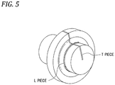
- the structure is thinly cut in one direction to collect a cut piece (T piece) and is thinly cut in a direction perpendicular to the one direction to collect a cut piece (L piece).
- the residual stress is a value obtained by multiplying elastic strain by a Young's modulus
- measuring elastic strain is equivalent to measuring residual stress. Accordingly, either elastic strain or residual stress may be measured from the cut piece. In the embodiment, a case of measuring the residual stress will be described.
- a T piece is obtained by cutting the structure in a radial direction. If the inherent strain is uniformly distributed in the circumferential direction, even in a case where a T piece is obtained from any portion in the circumferential direction, the inherent strain does not change. Accordingly, the T piece to be collected may be only one. Accordingly, the number of T pieces to be collected can be reduced. Thus, it is possible to reduce the workload of the cutting processing and the measurement of the residual stress of the cut piece.
- a conical cut piece (hereinafter, referred to as "C piece") cut in a direction normal to the bent surface may be collected.
- each view is a cross-sectional view when the journal shaft is cut in the rotation axis length direction.
- a C piece 500 is obtained by cutting the structure in a direction normal to the bent surface of the fillet, that is, in the radius direction of the arc-shaped fillet in the section. Since the journal shaft has an axis-symmetric shape, a cut face 501 of the C piece 500 conically extends around the rotation center axis of the journal shaft.
- Several C pieces are collected by changing the central angle of the fillet (in Fig. 6 , from 20° to 110° with a step of 10°).
- the user directly measures the residual stress of the cut piece collected as described above with X-rays or the like.
- the user attaches a strain gauge to the cut piece and further cuts the cut piece into a plurality of small pieces to measure released strain (elastic strain) of each small piece.
- released strain elastic strain
- a plurality of components that are different from each other are measured.
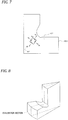
- FIG. 7 illustrates an example of measuring residual stress in a T piece of the fillet portion of the journal shaft (or pin shaft).
- a T piece 400 has a cut face 401 that is perpendicular to the circumferential direction of the journal shaft (or pin shaft), and the user measures components ⁇ r and ⁇ z in an r-direction and a z-direction perpendicular to each other in the cut face 401.
- these two components are measured in the T piece, and two direction components perpendicular to each other are also measured in the L piece (or C piece).
- a shear component ⁇ rz as well as the components ⁇ r and ⁇ z can be measured.
- three components ⁇ r , ⁇ z , and ⁇ rz can be measured with only the T piece 400.
- the estimation accuracy of the residual stress is improved in the case of using three components compared to the case of using two components of the T piece 400.
- the workload can be reduced as the number of cut pieces to be collected becomes smaller.
- the residual stress can be estimated by measurement of only two components of the T piece without measurement of the shear component. In this case, the collection of the L piece and the C piece can also be omitted, and the workload is reduced. However, since the residual stress cannot be estimated in consideration of components other than the above two components, the estimation accuracy becomes lower compared with the case of using the shear component ⁇ rz and the case of collecting the L piece or the C piece.
- Fig. 4 is referred to again.
- the user inputs the residual stress of the cut piece to the residual stress estimation device 1.
- the CPU 111 of the residual stress estimation device 1 receives the residual stress of the cut piece input from the input unit 12 (Step S2).
- the CPU 111 determines a distribution function of the inherent strain (Step S3).
- the distribution function any multi-order polynomial or trigonometrical series can be selected.
- the CPU 111 may automatically select the distribution function or the user may designate a desired distribution function using the input unit 12.
- the distribution function may be set in advance.
- Step S3 The distribution function determined in Step S3 is optimized for the plastic-worked structure. This will be described below.
- strain due to the work occurs in the structure.
- ⁇ e represents elastic strain
- ⁇ p plastic strain
- ⁇ th represents heat strain
- ⁇ tr represents transformation strain
- ⁇ cr creep strain
- the inherent strain refers to permanent strain caused inside the structure by a thermally or mechanically external force (non-elastic strain). That is, the sum of non-elastic terms other than ⁇ e and ⁇ th in Expression (10) is the inherent strain.
- ⁇ v represents volume strain
- suffixes (11, 22, 33) correspond to the respective components (r, ⁇ , z) in the case of a cylindrical coordinate system, respectively, and correspond to the respective components (x, y, z) in the case of an orthogonal coordinate system, respectively.
- a distribution function expressed by Expression (8) is defined in detail. When the distribution function is a multi-order polynomial, it is expressed by Expression (12).
- the residual stress estimation method according to the present embodiment can be used not only for the plastic-worked structure but also for the structure in which the inherent strain occupied mainly by the plastic strain occurs.
- Step S4 the CPU 111 optimizes the parameters of the distribution function.
- Step S4 the processing of Step S4 will be described in detail.
- the CPU 111 first determines H in Expression (9).
- the procedure thereof is as follows.
- the CPU 111 determines "a" such that R of Expression (7) is the minimum. Accordingly, the distribution function parameters are optimized.
- the CPU 111 calculates an estimated value of the residual stress (Step S5).
- Step S5 the CPU 111 obtains the inherent strain of a certain point by Expression (8). Further, the CPU 111 obtains "u” by solving Expression (4) and the obtained "u” is applied to Expression (3) to obtain ⁇ . Then, the obtained ⁇ is applied to Expression (1) to obtain ⁇ .
- the CPU 111 displays the estimated value of the obtained residual stress on the display unit 13 (Step S6).
- Step S6 the CPU 111 ends the processing.
- the inventor(s) conducted performance evaluation tests of the residual stress estimation method described in the above embodiments.
- a correct answer value of the residual stress conducted a numerical experiment by a residual stress estimation method (hereinafter, referred to as a "proposed method"), in which the incompressible constraint condition is introduced, using the results of the existing FEM (finite element method) analysis, and compared the correct answer value with the numerical experiment results.
- FEM finite element method
- Fig. 8 is a perspective view illustrating an analysis model. An axially symmetric shape was considered, the analysis model was set at 30° in the circumferential direction, and symmetric conditions in the circumferential direction were applied to a circumferential end face. Further, a center plane (section at the position of 15°) in the circumferential direction of the analysis model was taken as an evaluation section, and the analysis results in this evaluation section were used as the correct answer value.
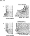
- Fig. 9A is a diagram illustrating an analysis model of a T piece
- Fig. 9B is a diagram illustrating an analysis model of a C piece.
- a value at an element center of gravity was used for the residual stress value of the cut piece.
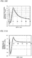
- Figs. 10A to 10C are graphs illustrating the results of Test 1.
- Fig. 10A is a graph illustrating estimation results of residual stress in a fillet circumferential direction
- Fig. 10B is a graph illustrating estimation results of residual stress in a pin circumferential direction
- Fig. 10C is a graph illustrating estimation results of residual stress in a fillet radial direction.
- a vertical axis shows the magnitude of the residual stress
- a horizontal axis shows the depth from the surface.
- the gray solid line shows the correct answer value
- the dashed line shows the results of numerical experiment by the comparative method
- the black solid line shows the results of numerical experiment by the proposed method.
- the proposed method obtains the residual stress in the fillet radial direction closer to the correct answer value in the vicinity of the surface, as compared with the comparative method. By considering incompressibility, it is possible to estimate the residual stress with high accuracy.
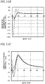
- Figs. 11A to 11C are graphs illustrating the results of Test 2.
- Fig. 11A is a graph illustrating estimation results of residual stress in a fillet circumferential direction
- Fig. 11B is a graph illustrating estimation results of residual stress in a pin circumferential direction
- Fig. 11C is a graph illustrating estimation results of residual stress in a fillet radial direction.
- a vertical axis shows the magnitude of the residual stress
- a horizontal axis shows the depth from the surface.
- the gray solid line shows the correct answer value
- the dashed line shows the results of numerical experiment by the comparative method
- the black solid line shows the results of numerical experiment by the proposed method.
- the residual stress in the ⁇ -direction can also be accurately estimated to the same extent as in Test 1 even when the measurement component in the ⁇ -direction other than the cut face of the T piece is not used.
- the estimation accuracy of the residual stress in the ⁇ -direction extremely deteriorates in the comparative method. By considering the incompressible constraint condition, it can be seen that the estimation accuracy is improved.
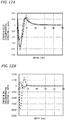
- Figs. 12A to 12C are graphs illustrating the results of Test 2.
- Fig. 12A is a graph illustrating estimation results of residual stress in a fillet circumferential direction
- Fig. 12B is a graph illustrating estimation results of residual stress in a pin circumferential direction
- Fig. 12C is a graph illustrating estimation results of residual stress in a fillet radial direction.
- a vertical axis shows the magnitude of the residual stress
- a horizontal axis shows the depth from the surface.
- the gray solid line shows the correct answer value
- the dashed line shows the results of numerical experiment by the comparative method
- the black solid line shows the results of numerical experiment by the proposed method.
- the estimation accuracy of the residual stress in the ⁇ -direction not using the measured value has decreased, the accuracy degradation is low in the proposed method compared with the comparative method.
- the estimation accuracy of the residual stress in the r-direction and the z-direction using the measured value is also extremely low in the comparative method.
- the estimation accuracy of the residual stress in the r-direction and the z-direction is good in the proposed method. From this result, it can also be seen that the estimation accuracy is improved by considering the incompressible constraint condition.
- the residual stress estimation method and the residual stress estimation device of the present invention are useful as a residual stress estimation method and a residual stress estimation device for estimating the residual stress of a structure based on an inherent strain method.
Landscapes
- Physics & Mathematics (AREA)
- Engineering & Computer Science (AREA)
- General Physics & Mathematics (AREA)
- Theoretical Computer Science (AREA)
- Computer Hardware Design (AREA)
- Evolutionary Computation (AREA)
- Geometry (AREA)
- General Engineering & Computer Science (AREA)
- Investigating Strength Of Materials By Application Of Mechanical Stress (AREA)
- Architecture (AREA)
- Software Systems (AREA)
Claims (6)
- Procédé d'estimation de tension résiduelle comprenant :une étape (S1) consistant à mesurer une valeur mesurée de tension résiduelle ou de déformation élastique à partir d'une pièce de coupe (400) d'une structure travaillée en plastique à une position de mesure ;une étape (S3) consistant à introduire comme condition de contrainte que la structure travaillée en plastique n'a pas subi de changement de volume avant et après le travail du plastique afin de se rapprocher d'une fonction de répartition de la déformation inhérente de la structure travaillée en plastique ;une étape (S4) consistant à déterminer un paramètre de la fonction de répartition de sorte qu'une erreur entre la valeur mesurée de tension résiduelle ou de déformation élastique de la structure travaillée en plastique et une valeur calculée de tension résiduelle ou de déformation élastique à la position de mesure soit au minimum ; etune étape (S5) consistant à estimer la tension résiduelle de la structure travaillée en plastique sur la base de la fonction de répartition pour laquelle le paramètre est déterminé.
- Procédé d'estimation de tension résiduelle selon la revendication 1, comprenant en outre :
une étape consistant à acquérir trois composantes (σr, σz, Trz) différentes concernant l'une quelconque parmi la tension résiduelle et la déformation élastique mesurées à partir d'une pièce de coupe (400) prélevée dans la structure, comme valeur mesurée. - Procédé d'estimation de tension résiduelle selon la revendication 2, dans lequel l'étape consistant à acquérir les trois composantes (σr, σz, Trz) comme valeur mesurée comporte l'acquisition de composantes de direction (σr, σz) dans deux directions perpendiculaires l'une à l'autre concernant l'une quelconque parmi la tension résiduelle et la déformation élastique mesurées sur une face de coupe (401) de la pièce de coupe (400) et une composante de cisaillement (Trz) dans la face de coupe (401), comme valeur mesurée.
- Procédé d'estimation de tension résiduelle selon la revendication 2 ou 3, dans lequel l'étape consistant à acquérir les trois composantes (σr, σz, Trz) comme valeur mesurée comporte, lorsqu'on suppose que la déformation inhérente est uniformément répartie dans une direction, l'acquisition de trois composantes (σr, σz, Trz) concernant l'une quelconque parmi la tension résiduelle et la déformation élastique mesurées sur une face de coupe (401) coupant ladite direction, comme valeur mesurée.
- Procédé d'estimation de tension résiduelle selon la revendication 1, comprenant en outre :
lorsqu'on suppose que la déformation inhérente est uniformément répartie dans une direction, une étape consistant à acquérir la valeur mesurée à partir d'une pièce de coupe (400) par rapport à une région dans laquelle la déformation inhérente est uniformément répartie. - Dispositif d'estimation de tension résiduelle (1) configuré pour réaliser un procédé d'estimation de tension résiduelle selon la revendication 1, le dispositif d'estimation tension résiduelle (1) comprenant :une unité d'entrée (12) pour entrer une valeur mesurée de tension résiduelle ou de déformation élastique mesurée à partir d'une pièce de coupe (400) d'une structure travaillée en plastique à une position de mesure au dispositif d'estimation tension résiduelle (1) ;une unité de détermination configurée pour introduire comme condition de contrainte que la structure travaillée en plastique n'a pas subi de changement de volume avant et après le travail du plastique afin de se rapprocher de la fonction de répartition de la déformation inhérente de la structure travaillée en plastique, et déterminer un paramètre de la fonction de répartition de sorte qu'une erreur entre la valeur mesurée de tension résiduelle ou de déformation élastique de la structure travaillée en plastique et une valeur calculée de tension résiduelle ou de déformation élastique à la position de mesure soit au minimum ;une unité d'acquisition de valeur estimée configurée pour acquérir une valeur estimée de la tension résiduelle dans la structure travaillée en plastique sur la base de la fonction de répartition pour laquelle le paramètre est déterminé par l'unité de détermination ; etune unité d'affichage (13) configurée pour afficher la valeur estimée acquise par l'unité d'acquisition de la valeur estimée.
Applications Claiming Priority (2)
| Application Number | Priority Date | Filing Date | Title |
|---|---|---|---|
| JP2015043081A JP6516323B2 (ja) | 2015-03-05 | 2015-03-05 | 残留応力推定方法及び残留応力推定装置 |
| PCT/JP2016/055072 WO2016140094A1 (fr) | 2015-03-05 | 2016-02-22 | Procédé et dispositif d'estimation de contrainte résiduelle |
Publications (3)
| Publication Number | Publication Date |
|---|---|
| EP3267341A1 EP3267341A1 (fr) | 2018-01-10 |
| EP3267341A4 EP3267341A4 (fr) | 2018-10-31 |
| EP3267341B1 true EP3267341B1 (fr) | 2020-04-22 |
Family
ID=56845019
Family Applications (1)
| Application Number | Title | Priority Date | Filing Date |
|---|---|---|---|
| EP16758788.0A Not-in-force EP3267341B1 (fr) | 2015-03-05 | 2016-02-22 | Procédé et dispositif d'estimation de contrainte résiduelle |
Country Status (7)
| Country | Link |
|---|---|
| US (1) | US11125634B2 (fr) |
| EP (1) | EP3267341B1 (fr) |
| JP (1) | JP6516323B2 (fr) |
| KR (1) | KR101941811B1 (fr) |
| CN (1) | CN107430637B (fr) |
| ES (1) | ES2788735T3 (fr) |
| WO (1) | WO2016140094A1 (fr) |
Families Citing this family (13)
| Publication number | Priority date | Publication date | Assignee | Title |
|---|---|---|---|---|
| JP6867329B2 (ja) * | 2018-04-25 | 2021-04-28 | 株式会社神戸製鋼所 | 残留応力算出方法 |
| EP3862904B1 (fr) * | 2018-11-06 | 2023-11-01 | JFE Steel Corporation | Analyse de vibration de noyau de fer stratifié |
| JP7290213B2 (ja) * | 2018-12-14 | 2023-06-13 | 学校法人 工学院大学 | 内部欠陥の検出方法及び内部欠陥の検出装置 |
| CN109614724A (zh) * | 2018-12-17 | 2019-04-12 | 重庆大学 | 一种关于机床关重件残余应力水平的评估方法 |
| CN113158351B (zh) * | 2020-01-22 | 2024-08-27 | 上海飞机制造有限公司 | 一种有限元仿真模型的构建方法、装置、设备及存储介质 |
| CN111444645B (zh) * | 2020-03-09 | 2023-06-20 | 扬州大学 | 一种基于残余应力间隙状态的港机损伤定位方法 |
| CN111460702B (zh) * | 2020-03-09 | 2023-06-20 | 扬州大学 | 一种基于正逆向损伤特征融合的结构件损伤识别方法 |
| CN111366283A (zh) * | 2020-03-30 | 2020-07-03 | 中国科学院金属研究所 | 一种辅助压痕应变法检测焊接结构件残余应力的方法 |
| CN112304478B (zh) * | 2020-07-30 | 2021-09-28 | 北京航空航天大学 | 一种基于蠕变轮廓法的残余应力测试方法 |
| CN112149330B (zh) * | 2020-09-24 | 2024-02-06 | 河海大学常州校区 | 一种风电塔筒油封平台焊接残余应力预测、焊接工艺优化方法 |
| TWI788873B (zh) * | 2021-06-08 | 2023-01-01 | 逢甲大學 | 多層薄膜界面應力與殘留應力之量測方法及裝置 |
| CN115374666B (zh) * | 2022-07-13 | 2024-04-23 | 上海交通大学 | 基于变形释放的喷丸固有应变反求方法及系统 |
| CN115470672A (zh) * | 2022-09-13 | 2022-12-13 | 华中科技大学 | 一种空间残余应力重构方法 |
Family Cites Families (18)
| Publication number | Priority date | Publication date | Assignee | Title |
|---|---|---|---|---|
| JPS5973119A (ja) * | 1982-10-21 | 1984-04-25 | Sumitomo Metal Ind Ltd | 圧延材料のクラウンおよび平坦度の矯正方法 |
| JPH05223661A (ja) * | 1992-02-17 | 1993-08-31 | Babcock Hitachi Kk | 残留応力の測定方法 |
| AU8019200A (en) * | 1999-10-13 | 2001-04-23 | Hytec, Inc. | Real-time interferometric deformation analysis |
| US20030021559A1 (en) * | 2001-07-30 | 2003-01-30 | Alcatel | Functionally tensioned optical fibers to form ribbons with controlled geometry, optimized residual strain and reduced attenuation |
| JP3932855B2 (ja) | 2001-10-19 | 2007-06-20 | 株式会社日立製作所 | 残留応力予測方法及び装置 |
| JP4533621B2 (ja) | 2003-12-22 | 2010-09-01 | 三菱重工業株式会社 | 残留応力測定方法及び装置 |
| JP4371985B2 (ja) * | 2004-11-30 | 2009-11-25 | 株式会社豊田中央研究所 | 応力解析方法、プログラムおよび記録媒体 |
| JP2007278842A (ja) * | 2006-04-06 | 2007-10-25 | Kobe Steel Ltd | 変態塑性ひずみ測定装置および変態塑性ひずみ測定方法 |
| JP2009059255A (ja) * | 2007-08-31 | 2009-03-19 | Phifit Kk | 塑性加工シミュレータ及び記録媒体 |
| CN101559511B (zh) * | 2009-05-22 | 2011-12-28 | 清华大学 | 一种以温度为控制变量的焊接数值模拟计算方法 |
| JP2011159213A (ja) | 2010-02-03 | 2011-08-18 | Hitachi Ltd | 溶接変形解析方法 |
| JP5011416B2 (ja) * | 2010-03-25 | 2012-08-29 | 日立Geニュークリア・エナジー株式会社 | ウォータージェットピーニングの残留応力評価方法及びウォータージェットピーニング施工方法 |
| JP5059224B2 (ja) * | 2010-11-09 | 2012-10-24 | 新日本製鐵株式会社 | 部品の疲労破壊評価装置、部品の疲労破壊評価方法、及びコンピュータプログラム |
| KR101458159B1 (ko) * | 2013-02-22 | 2014-11-05 | 연세대학교 산학협력단 | 불확실한 하중을 받는 보 부재의 변형률 분포 추정 장치 및 방법 |
| JP6163643B2 (ja) * | 2013-04-30 | 2017-07-19 | 学校法人 工学院大学 | 残留応力推定方法、ひずみ推定方法、残留応力推定システム、ひずみ推定システムおよびプログラム |
| CN103344555A (zh) * | 2013-07-09 | 2013-10-09 | 江苏科技大学 | 一种基于小孔法测试数据构建薄板焊接残余应力场的方法 |
| JP2015018500A (ja) | 2013-07-12 | 2015-01-29 | 株式会社東芝 | 解析装置、解析方法、および解析プログラム |
| JP5955301B2 (ja) * | 2013-11-14 | 2016-07-20 | 株式会社神戸製鋼所 | 残留応力算出方法 |
-
2015
- 2015-03-05 JP JP2015043081A patent/JP6516323B2/ja active Active
-
2016
- 2016-02-22 WO PCT/JP2016/055072 patent/WO2016140094A1/fr not_active Ceased
- 2016-02-22 ES ES16758788T patent/ES2788735T3/es active Active
- 2016-02-22 KR KR1020177024622A patent/KR101941811B1/ko not_active Expired - Fee Related
- 2016-02-22 EP EP16758788.0A patent/EP3267341B1/fr not_active Not-in-force
- 2016-02-22 US US15/554,357 patent/US11125634B2/en not_active Expired - Fee Related
- 2016-02-22 CN CN201680013938.4A patent/CN107430637B/zh not_active Expired - Fee Related
Non-Patent Citations (1)
| Title |
|---|
| None * |
Also Published As
| Publication number | Publication date |
|---|---|
| JP2016162381A (ja) | 2016-09-05 |
| EP3267341A4 (fr) | 2018-10-31 |
| ES2788735T3 (es) | 2020-10-22 |
| US11125634B2 (en) | 2021-09-21 |
| WO2016140094A1 (fr) | 2016-09-09 |
| JP6516323B2 (ja) | 2019-05-22 |
| CN107430637B (zh) | 2021-05-14 |
| KR20170110126A (ko) | 2017-10-10 |
| KR101941811B1 (ko) | 2019-01-23 |
| EP3267341A1 (fr) | 2018-01-10 |
| US20180038750A1 (en) | 2018-02-08 |
| CN107430637A (zh) | 2017-12-01 |
Similar Documents
| Publication | Publication Date | Title |
|---|---|---|
| EP3267341B1 (fr) | Procédé et dispositif d'estimation de contrainte résiduelle | |
| EP3267166B1 (fr) | Procédé et dispositif d'estimation de contrainte résiduelle | |
| EP3267167B1 (fr) | Procédé et dispositif d'estimation de contrainte résiduelle | |
| Cornwell et al. | Application of the strain energy damage detection method to plate-like structures | |
| JP6119451B2 (ja) | 薄板レーザ溶接部の疲労寿命予測方法 | |
| Kahya et al. | Damage localization in laminated composite beams with multiple edge cracks based on vibration measurements | |
| JP4533621B2 (ja) | 残留応力測定方法及び装置 | |
| CN110362896A (zh) | 基于非线性度的飞机结构静强度试验数据筛选方法及设备 | |
| CN113688544A (zh) | 一种主被动结合的复合材料损伤定量辨识方法 | |
| JP6650328B2 (ja) | 残留応力推定方法及び残留応力推定装置 | |
| CN112733399A (zh) | 随机振动中螺栓的失效评估方法、装置 | |
| JP2019082985A (ja) | 非線形応力ひずみ解析装置、非線形応力ひずみ解析方法、及び非線形応力ひずみ解析プログラム | |
| JP4441397B2 (ja) | 地震応答解析装置、地震応答解析方法及び地震応答解析プログラム | |
| WO2020017042A1 (fr) | Procédé d'évaluation, dispositif d'évaluation et support d'enregistrement | |
| Vecchio et al. | Numerical Evaluation of Damage Distribution over a Slat Track Using Flight Test Data | |
| JP6375963B2 (ja) | 構造体の力学的弱点を発見可能な構造体設計支援装置 | |
| JP2026004012A (ja) | ゴム材料特性予測方法 | |
| Fässler | Axial load determination using modal analysis | |
| CN112632834A (zh) | 地震中螺栓的失效评估方法、装置 | |
| Kenner et al. | Step Ladder Failure Analysis: A Comparison of Analytical Methods |
Legal Events
| Date | Code | Title | Description |
|---|---|---|---|
| STAA | Information on the status of an ep patent application or granted ep patent |
Free format text: STATUS: THE INTERNATIONAL PUBLICATION HAS BEEN MADE |
|
| PUAI | Public reference made under article 153(3) epc to a published international application that has entered the european phase |
Free format text: ORIGINAL CODE: 0009012 |
|
| STAA | Information on the status of an ep patent application or granted ep patent |
Free format text: STATUS: REQUEST FOR EXAMINATION WAS MADE |
|
| 17P | Request for examination filed |
Effective date: 20170901 |
|
| AK | Designated contracting states |
Kind code of ref document: A1 Designated state(s): AL AT BE BG CH CY CZ DE DK EE ES FI FR GB GR HR HU IE IS IT LI LT LU LV MC MK MT NL NO PL PT RO RS SE SI SK SM TR |
|
| AX | Request for extension of the european patent |
Extension state: BA ME |
|
| DAV | Request for validation of the european patent (deleted) | ||
| DAX | Request for extension of the european patent (deleted) | ||
| A4 | Supplementary search report drawn up and despatched |
Effective date: 20181004 |
|
| RIC1 | Information provided on ipc code assigned before grant |
Ipc: G01L 5/00 20060101ALI20180926BHEP Ipc: G01L 1/00 20060101ALI20180926BHEP Ipc: G06F 17/50 20060101AFI20180926BHEP |
|
| STAA | Information on the status of an ep patent application or granted ep patent |
Free format text: STATUS: EXAMINATION IS IN PROGRESS |
|
| 17Q | First examination report despatched |
Effective date: 20190724 |
|
| GRAP | Despatch of communication of intention to grant a patent |
Free format text: ORIGINAL CODE: EPIDOSNIGR1 |
|
| STAA | Information on the status of an ep patent application or granted ep patent |
Free format text: STATUS: GRANT OF PATENT IS INTENDED |
|
| INTG | Intention to grant announced |
Effective date: 20191112 |
|
| GRAS | Grant fee paid |
Free format text: ORIGINAL CODE: EPIDOSNIGR3 |
|
| GRAA | (expected) grant |
Free format text: ORIGINAL CODE: 0009210 |
|
| STAA | Information on the status of an ep patent application or granted ep patent |
Free format text: STATUS: THE PATENT HAS BEEN GRANTED |
|
| REG | Reference to a national code |
Ref country code: DE Ref legal event code: R079 Ref document number: 602016034587 Country of ref document: DE Free format text: PREVIOUS MAIN CLASS: G06F0017500000 Ipc: G06F0030000000 |
|
| AK | Designated contracting states |
Kind code of ref document: B1 Designated state(s): AL AT BE BG CH CY CZ DE DK EE ES FI FR GB GR HR HU IE IS IT LI LT LU LV MC MK MT NL NO PL PT RO RS SE SI SK SM TR |
|
| REG | Reference to a national code |
Ref country code: CH Ref legal event code: EP |
|
| REG | Reference to a national code |
Ref country code: DE Ref legal event code: R096 Ref document number: 602016034587 Country of ref document: DE |
|
| REG | Reference to a national code |
Ref country code: IE Ref legal event code: FG4D |
|
| REG | Reference to a national code |
Ref country code: AT Ref legal event code: REF Ref document number: 1261054 Country of ref document: AT Kind code of ref document: T Effective date: 20200515 |
|
| REG | Reference to a national code |
Ref country code: FI Ref legal event code: FGE |
|
| REG | Reference to a national code |
Ref country code: NO Ref legal event code: T2 Effective date: 20200422 |
|
| REG | Reference to a national code |
Ref country code: LT Ref legal event code: MG4D |
|
| REG | Reference to a national code |
Ref country code: NL Ref legal event code: MP Effective date: 20200422 |
|
| REG | Reference to a national code |
Ref country code: ES Ref legal event code: FG2A Ref document number: 2788735 Country of ref document: ES Kind code of ref document: T3 Effective date: 20201022 |
|
| PG25 | Lapsed in a contracting state [announced via postgrant information from national office to epo] |
Ref country code: GR Free format text: LAPSE BECAUSE OF FAILURE TO SUBMIT A TRANSLATION OF THE DESCRIPTION OR TO PAY THE FEE WITHIN THE PRESCRIBED TIME-LIMIT Effective date: 20200723 Ref country code: SE Free format text: LAPSE BECAUSE OF FAILURE TO SUBMIT A TRANSLATION OF THE DESCRIPTION OR TO PAY THE FEE WITHIN THE PRESCRIBED TIME-LIMIT Effective date: 20200422 Ref country code: PT Free format text: LAPSE BECAUSE OF FAILURE TO SUBMIT A TRANSLATION OF THE DESCRIPTION OR TO PAY THE FEE WITHIN THE PRESCRIBED TIME-LIMIT Effective date: 20200824 Ref country code: LT Free format text: LAPSE BECAUSE OF FAILURE TO SUBMIT A TRANSLATION OF THE DESCRIPTION OR TO PAY THE FEE WITHIN THE PRESCRIBED TIME-LIMIT Effective date: 20200422 Ref country code: NL Free format text: LAPSE BECAUSE OF FAILURE TO SUBMIT A TRANSLATION OF THE DESCRIPTION OR TO PAY THE FEE WITHIN THE PRESCRIBED TIME-LIMIT Effective date: 20200422 Ref country code: IS Free format text: LAPSE BECAUSE OF FAILURE TO SUBMIT A TRANSLATION OF THE DESCRIPTION OR TO PAY THE FEE WITHIN THE PRESCRIBED TIME-LIMIT Effective date: 20200822 |
|
| REG | Reference to a national code |
Ref country code: AT Ref legal event code: MK05 Ref document number: 1261054 Country of ref document: AT Kind code of ref document: T Effective date: 20200422 |
|
| PG25 | Lapsed in a contracting state [announced via postgrant information from national office to epo] |
Ref country code: RS Free format text: LAPSE BECAUSE OF FAILURE TO SUBMIT A TRANSLATION OF THE DESCRIPTION OR TO PAY THE FEE WITHIN THE PRESCRIBED TIME-LIMIT Effective date: 20200422 Ref country code: BG Free format text: LAPSE BECAUSE OF FAILURE TO SUBMIT A TRANSLATION OF THE DESCRIPTION OR TO PAY THE FEE WITHIN THE PRESCRIBED TIME-LIMIT Effective date: 20200722 Ref country code: HR Free format text: LAPSE BECAUSE OF FAILURE TO SUBMIT A TRANSLATION OF THE DESCRIPTION OR TO PAY THE FEE WITHIN THE PRESCRIBED TIME-LIMIT Effective date: 20200422 Ref country code: LV Free format text: LAPSE BECAUSE OF FAILURE TO SUBMIT A TRANSLATION OF THE DESCRIPTION OR TO PAY THE FEE WITHIN THE PRESCRIBED TIME-LIMIT Effective date: 20200422 |
|
| PG25 | Lapsed in a contracting state [announced via postgrant information from national office to epo] |
Ref country code: AL Free format text: LAPSE BECAUSE OF FAILURE TO SUBMIT A TRANSLATION OF THE DESCRIPTION OR TO PAY THE FEE WITHIN THE PRESCRIBED TIME-LIMIT Effective date: 20200422 |
|
| REG | Reference to a national code |
Ref country code: DE Ref legal event code: R097 Ref document number: 602016034587 Country of ref document: DE |
|
| PG25 | Lapsed in a contracting state [announced via postgrant information from national office to epo] |
Ref country code: DK Free format text: LAPSE BECAUSE OF FAILURE TO SUBMIT A TRANSLATION OF THE DESCRIPTION OR TO PAY THE FEE WITHIN THE PRESCRIBED TIME-LIMIT Effective date: 20200422 Ref country code: IT Free format text: LAPSE BECAUSE OF FAILURE TO SUBMIT A TRANSLATION OF THE DESCRIPTION OR TO PAY THE FEE WITHIN THE PRESCRIBED TIME-LIMIT Effective date: 20200422 Ref country code: SM Free format text: LAPSE BECAUSE OF FAILURE TO SUBMIT A TRANSLATION OF THE DESCRIPTION OR TO PAY THE FEE WITHIN THE PRESCRIBED TIME-LIMIT Effective date: 20200422 Ref country code: RO Free format text: LAPSE BECAUSE OF FAILURE TO SUBMIT A TRANSLATION OF THE DESCRIPTION OR TO PAY THE FEE WITHIN THE PRESCRIBED TIME-LIMIT Effective date: 20200422 Ref country code: CZ Free format text: LAPSE BECAUSE OF FAILURE TO SUBMIT A TRANSLATION OF THE DESCRIPTION OR TO PAY THE FEE WITHIN THE PRESCRIBED TIME-LIMIT Effective date: 20200422 Ref country code: AT Free format text: LAPSE BECAUSE OF FAILURE TO SUBMIT A TRANSLATION OF THE DESCRIPTION OR TO PAY THE FEE WITHIN THE PRESCRIBED TIME-LIMIT Effective date: 20200422 Ref country code: EE Free format text: LAPSE BECAUSE OF FAILURE TO SUBMIT A TRANSLATION OF THE DESCRIPTION OR TO PAY THE FEE WITHIN THE PRESCRIBED TIME-LIMIT Effective date: 20200422 |
|
| PG25 | Lapsed in a contracting state [announced via postgrant information from national office to epo] |
Ref country code: PL Free format text: LAPSE BECAUSE OF FAILURE TO SUBMIT A TRANSLATION OF THE DESCRIPTION OR TO PAY THE FEE WITHIN THE PRESCRIBED TIME-LIMIT Effective date: 20200422 Ref country code: SK Free format text: LAPSE BECAUSE OF FAILURE TO SUBMIT A TRANSLATION OF THE DESCRIPTION OR TO PAY THE FEE WITHIN THE PRESCRIBED TIME-LIMIT Effective date: 20200422 |
|
| PLBE | No opposition filed within time limit |
Free format text: ORIGINAL CODE: 0009261 |
|
| STAA | Information on the status of an ep patent application or granted ep patent |
Free format text: STATUS: NO OPPOSITION FILED WITHIN TIME LIMIT |
|
| 26N | No opposition filed |
Effective date: 20210125 |
|
| PG25 | Lapsed in a contracting state [announced via postgrant information from national office to epo] |
Ref country code: SI Free format text: LAPSE BECAUSE OF FAILURE TO SUBMIT A TRANSLATION OF THE DESCRIPTION OR TO PAY THE FEE WITHIN THE PRESCRIBED TIME-LIMIT Effective date: 20200422 |
|
| PG25 | Lapsed in a contracting state [announced via postgrant information from national office to epo] |
Ref country code: MC Free format text: LAPSE BECAUSE OF FAILURE TO SUBMIT A TRANSLATION OF THE DESCRIPTION OR TO PAY THE FEE WITHIN THE PRESCRIBED TIME-LIMIT Effective date: 20200422 |
|
| GBPC | Gb: european patent ceased through non-payment of renewal fee |
Effective date: 20210222 |
|
| REG | Reference to a national code |
Ref country code: BE Ref legal event code: MM Effective date: 20210228 |
|
| PG25 | Lapsed in a contracting state [announced via postgrant information from national office to epo] |
Ref country code: LU Free format text: LAPSE BECAUSE OF NON-PAYMENT OF DUE FEES Effective date: 20210222 Ref country code: LI Free format text: LAPSE BECAUSE OF NON-PAYMENT OF DUE FEES Effective date: 20210228 Ref country code: CH Free format text: LAPSE BECAUSE OF NON-PAYMENT OF DUE FEES Effective date: 20210228 |
|
| PG25 | Lapsed in a contracting state [announced via postgrant information from national office to epo] |
Ref country code: IE Free format text: LAPSE BECAUSE OF NON-PAYMENT OF DUE FEES Effective date: 20210222 Ref country code: GB Free format text: LAPSE BECAUSE OF NON-PAYMENT OF DUE FEES Effective date: 20210222 Ref country code: FR Free format text: LAPSE BECAUSE OF NON-PAYMENT OF DUE FEES Effective date: 20210228 |
|
| PG25 | Lapsed in a contracting state [announced via postgrant information from national office to epo] |
Ref country code: BE Free format text: LAPSE BECAUSE OF NON-PAYMENT OF DUE FEES Effective date: 20210228 |
|
| PGFP | Annual fee paid to national office [announced via postgrant information from national office to epo] |
Ref country code: NO Payment date: 20230208 Year of fee payment: 8 Ref country code: FI Payment date: 20230220 Year of fee payment: 8 Ref country code: ES Payment date: 20230310 Year of fee payment: 8 |
|
| P01 | Opt-out of the competence of the unified patent court (upc) registered |
Effective date: 20230523 |
|
| PG25 | Lapsed in a contracting state [announced via postgrant information from national office to epo] |
Ref country code: CY Free format text: LAPSE BECAUSE OF FAILURE TO SUBMIT A TRANSLATION OF THE DESCRIPTION OR TO PAY THE FEE WITHIN THE PRESCRIBED TIME-LIMIT Effective date: 20200422 |
|
| PG25 | Lapsed in a contracting state [announced via postgrant information from national office to epo] |
Ref country code: HU Free format text: LAPSE BECAUSE OF FAILURE TO SUBMIT A TRANSLATION OF THE DESCRIPTION OR TO PAY THE FEE WITHIN THE PRESCRIBED TIME-LIMIT; INVALID AB INITIO Effective date: 20160222 |
|
| PG25 | Lapsed in a contracting state [announced via postgrant information from national office to epo] |
Ref country code: MK Free format text: LAPSE BECAUSE OF FAILURE TO SUBMIT A TRANSLATION OF THE DESCRIPTION OR TO PAY THE FEE WITHIN THE PRESCRIBED TIME-LIMIT Effective date: 20200422 |
|
| PGFP | Annual fee paid to national office [announced via postgrant information from national office to epo] |
Ref country code: DE Payment date: 20231228 Year of fee payment: 9 |
|
| PG25 | Lapsed in a contracting state [announced via postgrant information from national office to epo] |
Ref country code: MT Free format text: LAPSE BECAUSE OF FAILURE TO SUBMIT A TRANSLATION OF THE DESCRIPTION OR TO PAY THE FEE WITHIN THE PRESCRIBED TIME-LIMIT Effective date: 20200422 |
|
| PG25 | Lapsed in a contracting state [announced via postgrant information from national office to epo] |
Ref country code: FI Free format text: LAPSE BECAUSE OF NON-PAYMENT OF DUE FEES Effective date: 20240222 |
|
| PG25 | Lapsed in a contracting state [announced via postgrant information from national office to epo] |
Ref country code: NO Free format text: LAPSE BECAUSE OF NON-PAYMENT OF DUE FEES Effective date: 20240229 Ref country code: FI Free format text: LAPSE BECAUSE OF NON-PAYMENT OF DUE FEES Effective date: 20240222 |
|
| REG | Reference to a national code |
Ref country code: ES Ref legal event code: FD2A Effective date: 20250402 |
|
| PG25 | Lapsed in a contracting state [announced via postgrant information from national office to epo] |
Ref country code: ES Free format text: LAPSE BECAUSE OF NON-PAYMENT OF DUE FEES Effective date: 20240223 |
|
| REG | Reference to a national code |
Ref country code: DE Ref legal event code: R119 Ref document number: 602016034587 Country of ref document: DE |
|
| PG25 | Lapsed in a contracting state [announced via postgrant information from national office to epo] |
Ref country code: TR Free format text: LAPSE BECAUSE OF FAILURE TO SUBMIT A TRANSLATION OF THE DESCRIPTION OR TO PAY THE FEE WITHIN THE PRESCRIBED TIME-LIMIT Effective date: 20200422 |
|
| PG25 | Lapsed in a contracting state [announced via postgrant information from national office to epo] |
Ref country code: DE Free format text: LAPSE BECAUSE OF NON-PAYMENT OF DUE FEES Effective date: 20250902 |