EP3267367A1 - Dispositif de disque de comptage - Google Patents
Dispositif de disque de comptage Download PDFInfo
- Publication number
- EP3267367A1 EP3267367A1 EP17175416.1A EP17175416A EP3267367A1 EP 3267367 A1 EP3267367 A1 EP 3267367A1 EP 17175416 A EP17175416 A EP 17175416A EP 3267367 A1 EP3267367 A1 EP 3267367A1
- Authority
- EP
- European Patent Office
- Prior art keywords
- imaging
- passage
- illumination
- section
- sheet
- Prior art date
- Legal status (The legal status is an assumption and is not a legal conclusion. Google has not performed a legal analysis and makes no representation as to the accuracy of the status listed.)
- Granted
Links
Images


Classifications
-
- G—PHYSICS
- G06—COMPUTING OR CALCULATING; COUNTING
- G06M—COUNTING MECHANISMS; COUNTING OF OBJECTS NOT OTHERWISE PROVIDED FOR
- G06M9/00—Counting of objects in a stack thereof
- G06M9/02—Counting of objects in a stack thereof by using a rotating separator incorporating pneumatic suction nozzles
Definitions
- the invention relates to a device for processing stacked sheets according to the preamble of claim 1 and to a method of using such a device.
- Conventional Zählinvorraumen can be designed to detect the number of stacked sheets, which are, for example, printed sheets of notes of value, such as stocks or banknotes or even stacks of such, already isolated notes of value.
- the publication EP 1 204 514 A1 describes a generic device comprising a base device for connection to a vacuum device for providing a negative pressure, a light source as well as a base device rotatably arranged and with this negative pressure and optically coupled counting disc.
- the counting disc comprises at least one, in particular a plurality of, each separated by an opening extending in the radial direction peripheral portions each having a leading in the direction of rotation tip or nose and a plurality of suction openings arranged on the underside.
- the device has an optical illumination path for illuminating at least a portion of a sheet of the sheets arranged in stack form and an optical pickup path for receiving the the illuminated leaf portion reflected and / or scattered light.
- the known device is designed in such a way that the light received via the optical recording path and reflected or scattered by the illuminated sheet section is set up to determine a distance between a side edge of the respective sheet and a printed image or to generate a counting pulse.
- the publication US 2007/0206192 A1 relates to an imaging system and method for operating in different modes of operation such as wide field microscopy or confocal microscopy of at least one sample.
- the system comprises at least one light source, an optical system placed in the operating mode of the microscope, and a detector adapted to selectively detect pixels.
- the at least one sample is moved relative to the optical system using a stepwise or continuous movement of the sample.
- the publication DE 10 2007 047 468 A1 relates to a method and an arrangement for the depth-resolved, optical detection of an illuminated sample, in which the sample or a part thereof is scanned by means of preferably line-shaped illumination, and the illumination of the sample in focus is periodically structured in at least one spatial direction, wherein light coming from the sample detected and images of the sample are generated and from an optical sectional image and / or an image with increased resolution is calculated by the sample.
- the invention has for its object to improve a generic device or its operation in terms of their functionality and / or their reliability.
- the device according to the invention is characterized in that the illumination passage for generating a linear illumination section are formed on the respective sheet and the receiving path as an imaging path for imaging the illuminated on the respective sheet linear portion in a detection plane.
- the processing of the sheets arranged in stack form can be functionally improved and made more flexible.
- the error resistance of the counting process can be improved compared to the generic device with which apart from the actual counting process alone a distance of a benefit (especially a partial product in the form of a printing section on a sheet) is determined by a blade edge, in particular to detect a cutting accuracy.
- a benefit especially a partial product in the form of a printing section on a sheet
- a blade edge in particular to detect a cutting accuracy.
- the device according to the invention in addition to the actual benefit in addition to a sheet applied information such as a one- or multi-dimensional coding or marking, detected and provided, for example, a higher-level control device for further processing.
- coding is to be understood as being general and may in particular be an optically detectable feature such as an imprinted or otherwise introduced feature on the sheets of the sheet stack, i. Scroll the sheet stack, include.
- the inventive device is suitable for processing any sheet stacks, wherein the respective sheets may be, for example, paper / cardboard or plastic foil sheets.
- the leaves can also be made of a composite material and / or sections made of different materials.
- the term "detection plane” is to be understood generally and may, for example, comprise a planar or a curved plane or a section with planar and / or curved regions.
- this detection plane for example, a sensor surface of an image sensor device, in particular a monochrome or polychromatic photosensor can be used, which can be designed to provide a captured image for digital further processing.
- linear illumination section can mean an approximately rectangular illuminated area, in which the long edge has at least twice, in particular at least three times, the extension of the short edge. It is within the scope of the invention, if the edges are not completely straight, instead they can also be curved, in particular slightly curved. Also, these "edges” may not represent a hard transition from the illumination portion to the unlit areas, but a smooth transition.
- illumination path or “imaging path” designates the respective optical arrangement for realizing the linear illumination section on the sheet or the image of this section in a detection plane.
- the line-shaped illumination section can be located immediately behind the lower or the upper end face of the counting disc, since the sheet of the stack which has just been processed can abut against this end face at least in sections.
- the indication "illumination section on the respective sheet” means a light field generated via the illumination aisle that depending on the embodiment, directly on the underside or directly on the upper side of the counting disc.
- light light source
- luminous flux density or illuminance are to be understood generally and must not be limited in all cases to the visible spectral range.
- an NIR laser can also be used as the light source, with all the optical components in the illumination passage or imaging path as well as the sensor device (s) being adapted thereto.
- the line-shaped illumination section on the respective sheet or the light field generated by means of the functionality of the illumination passage directly below or above the dial can be adapted to the respective application with regard to its dimensions.
- the width of the illumination line may be a few 5 ⁇ m, for example ⁇ 80 ⁇ m or ⁇ 50 ⁇ m, in particular ⁇ 30 ⁇ m.
- the perpendicular extent of the illumination strip is in the range of about one to 10 millimeters or more, in particular about 5 mm or about 7 mm.
- the latter expansion can be adapted to a dimension or dimensioning of an on the sheet attached, in particular printed coding, in particular the same size or slightly larger, so that the coding can be completely detected by the illumination strip in a certain direction.
- the overall optical system is set up in such a way that the line-shaped illumination section is oriented essentially radially relative to the counting disc with respect to its longitudinal axis and thus the width extension of the illumination section is oriented substantially tangentially to the counting disc.
- the optical system is set up in such a way that the ratio of the length / width of the line-shaped illumination section is ⁇ 50, in particular ⁇ 100 or even ⁇ 300.
- the light source can be arranged in particular as a component in the base device. In other embodiments, however, the light source may also be coupled to the base device from the outside to the optical illumination path, for example via a light guide. As the light source itself, different embodiments can be used within the scope of the invention, for example a halogen lamp with a high luminous flux or a gas laser. In a particularly expedient embodiment, the light source can be designed as a semiconductor light source, which can be set up in particular as a light source for emitting light of a first wavelength and light of a second wavelength.
- the light source can be suitably coupled on the input side to the illumination passage, wherein the illumination passage can have a plurality of beam-shaping elements in order to produce the desired line-shaped illumination section at the location of the respective sheet, i. to provide in the end of the lighting corridor.
- the illumination passage and the imaging passage are arranged in sections in the base device and sections in the counting disc, wherein the image sensor device is coupled to the imaging gear, in particular such that a photosensor of the image sensor device is arranged in the indicated detection plane.
- the image sensor device is arranged in or on the base device.
- the illumination passage in the base device has at least one optical series connection of a Powell lens and a cylindrical lens.
- a further spherical lens which is designed in combination with a negative cylindrical lens, as a converging lens and in the axis perpendicular to the cylinder axis represents a beam widening.
- this lens again provides a collimator which collimates the divergent radiation emitted by the Powell lens.
- optical series connections are particularly suitable when using the semiconductor light source described, in particular a laser diode, which has very different divergence angles in mutually perpendicular directions due to their geometric structure.
- a particularly effective symmetrization in the illumination passage can be achieved by connecting two Powell lenses which are oriented perpendicular to one another in succession, wherein an optical series connection of two cylindrical lenses can take place, wherein the two optically cascaded cylindrical lenses with respect to their excellent axis to each other are oriented vertically.
- Beam shaping elements are included for providing a planar and homogeneous light distribution in a predetermined plane of the illumination passage, said optical arrangement may be formed such that the predetermined plane is in the region of the transition between the base device and counting disc.
- this level can be arranged in the area of the counting disk, the base device or exactly between the two, but in any case in the region of the transition of the base device and the dial, so that any disturbances in this area have a low effect, since the light is homogeneously distributed.
- the optical illumination path has a ⁇ / 4 plate, which may preferably be arranged in the section of the illumination passage within the base device.
- This ⁇ / 4 plate can be oriented in the illumination passage so that the light emitted by the light source and propagating in the illumination passage is circularly polarized after passing through the ⁇ / 4 plate.
- the illumination passage in the device may comprise an optical series connection of a plurality of cylindrical lenses with different focal lengths for generating the linear illumination section on the sheet, in particular starting from the planar and homogeneous light distribution in the predetermined plane of the illumination passage.
- the described planar and homogeneous light distribution is transformed into the line-shaped field distribution of the optically cascaded cylindrical lenses to provide the linear illumination section on the sheet.
- the illumination passage and / or the imaging passage has an optically effective filter device for filtering light with predetermined properties such as Polarization and / or wavelength.
- predetermined properties such as Polarization and / or wavelength.
- the device according to the invention to the physical properties of the leaves or an applied, e.g. printed coding can be achieved by this measure, at least in some of embodiments, that extraneous light is not detected or only reduced, which otherwise could falsify, for example, the imaging of a two-dimensional code from the sheet to a photosensor.
- the illumination passage has a linear polarizer which can be arranged on the input side of the illumination passage section of the counting disc and the imaging passage has a linear polarizer which can be arranged on the output side of the imaging passage section of the counting disc, wherein the latter linear polarizer with respect may be oriented to the transmitted polarization perpendicular to the linear polarizer in the illumination portion of the Zählusion.
- the illumination passage and the imaging passage have at least one common optical element which can be arranged on or in the counting disc, wherein the common optical element can be designed in particular as a deflection prism.
- the common optical element may be formed and arranged to receive light from the illumination passage toward the line-shaped illumination portion of the sheet direct and reflected by the line-shaped illumination portion and / or scattered light and redirect in the imaging path.
- a transparent plate for closing the illumination passage and the imaging path with respect to dust and / or moisture at the end on the counting disk front side executed to the sheet, a transparent plate, in particular comprising two flat boundary surfaces can be provided, which advantageously completes both the illumination passage and the imaging passage.
- a transparent plate may for example be formed as a sapphire plate, which has good optical transmission properties and high hardness.
- both this plate and the prism internal to the disc in the dial can share optical elements of the illuminating passage and represent the picture course.
- the end plates do not necessarily have to have two planar boundary surfaces, it may also be appropriate in specific embodiments, the plates for light control with spherical surface or a spherical surface form, in particular as a cylindrical lens.
- an optical component arranged in the imaging path or illumination passage simultaneously acts as a protective or closure window for the respective illumination aisle or imaging passage section in FIG the counting disc or the base device is used.
- a component may in particular be an optical polarizer.
- the imaging path can have at least one imaging stage with refractive optical elements for producing an image of the line-shaped, illuminated sheet section in the detection plane, wherein the detection plane can lie in the imaging path section of the base device.
- This design measure ensures that an image capture device, for example a photosensor, can be arranged outside the rotating counting disc, which simplifies the electrical supply as well as the forwarding of the acquired data.
- the imaging scale of the at least one imaging stage is less than or equal to 1, in particular approximately 0.6. If the imaging path has several imaging stages connected in series, it can be provided that the imaging scale of the entire imaging path is ⁇ 1, in particular ⁇ 0.5 or in certain embodiments also ⁇ 0.2.
- the imaging path can expediently comprise an imaging stage with refractive optical elements for producing an intermediate image of the linear image section
- the intermediate image in the imaging path section may be the base device.
- To improve the transfer of the intermediate image to the detection plane can be provided to arrange a ground glass at the location of the intermediate image.
- the imaging path comprises a single imaging stage with refractive optical elements for generating the image of the linear image section, which image may lie in the imaging path section of the base device, and wherein a sensor surface of an image sensor device is arranged at the location of the image plane can.
- An imaging stage in the imaging path can comprise at least one cylindrical lens, in particular an optical series connection of two cylindrical lenses.
- a second imaging stage can be provided in the functionality of a lens for producing an image in the detection plane.
- a lens is arranged at the location of the intermediate image for imaging an exit pupil of the first imaging stage into an entrance pupil of the second imaging stage.
- the device according to the invention may preferably have a control device for controlling the exposure of an image sensor device arranged at the location of the detection plane (image plane) with respect to its sensor surface.
- the control device may be expedient, if the control device is set up, to determine the starting time of the exposure and the end time of the exposure, in particular for detecting the time duration within which the line-shaped illumination section depicted in the detection plane falls onto the sensor surface.
- the control device may be connected on the input side to the output of at least one optical sensor, such as a photodiode, for detecting the orientation of the illumination passage section of the base device with the respective one of the illumination passage sections the counting device.
- the respective optical components of the respective illumination passage section and / or of the respective imaging passage section in the counting disc and / or the base device it can be expedient to provide that the respective optical components are fastened on a respective carrier, e.g. are glued and the respective carrier is used as a module or insert in associated recesses in the counting disc or the base device and fixed.
- a pre-adjustment of the optical components on the respective carrier which is comparatively easy to perform, is provided prior to attachment in the counting disc or base device.
- the controller may control the exposure of the image sensing device in response to an output signal of the at least one optical sensor, such as a photodiode.
- the at least one optical sensor may be part of a, further comprising a light source having light barrier.
- light from the illumination light source can be detected by an optical sensor, such as a photodiode shortly before alignment of the illumination passage sections of the base device and the counting device rotating therewith, thereby determining the starting time of the exposure can be.
- the end time of the exposure of an image sensor can be determined by means of a calculation, in particular as a function of the rotational speed of the counting disk.
- a memory device may suitably be provided be provided, which feeds a data processing device.
- the captured image has an at least two-dimensional code, in particular a QR (Quick Response) code or a Data Matrix code, wherein the data processing means for decoding the at least two-dimensional Code can be set up in the captured image of the coding.
- this code is a three-dimensional code, for example in that a two-dimensional code is executed as a colored code, in particular printed, which is detected in a color-sensitive manner.
- Corresponding may be provided for this purpose to print on the stacked sheets in each case such a code, which can be detected optically with the device according to the invention and subsequently digitally processed.
- control device In order to control the illuminance in the detection plane (image plane), it can be expediently provided that the control device is designed to set or control or regulate the optical output power of the light source of the illumination passage.
- the device according to the invention is also suitable for detecting one-dimensional or multidimensional codes, for example 2D or 3D codes, which can be attached, in particular printed, to the sheets arranged in stack form.
- This feature of the device according to the invention may be particularly useful in a sheet processing system, especially if this coding represents a unique identifier for the identification of the respective sheet.
- the use of the device according to the invention for detecting a coding has the advantage of increased error safety over conventional detection devices. It can be provided that the line-shaped illumination section is aligned on the sheet approximately perpendicular to the barcode lines and extends over all the lines of the code. Upon rotation of the dial, the geometrical relationships with respect to the course of the line-shaped illumination sections can be set such that several sections of the entire barcode are imaged on the image sensor surface, thereby increasing the error resistance when using the device according to the invention, since all imaged linear illumination sections include the entire barcode.
- a method for processing stacked sheets comprising a base device to which a vacuum device for supplying a negative pressure is connected, and a counting disk which is rotated to the base device and coupled thereto vacuum-technically and optically intermittently.
- a line-shaped illumination section is produced on a sheet of the stack by means of a lighting passage extending through the counting disk and imaged into a detection plane by means of an imaging gear extending through the counting disk.
- a coding applied to the sheets in each case that a plurality of images of line-shaped lighting sections are detected in the detection or image plane and for recognition a mounted on the sheet coding are processed.
- This plurality of images result from the fact that in the course of sweeping the coding, the respective illumination line sections are imaged into different regions of the detection plane, ie in different regions of the sensor surface, since the imaging path section moves in the counting disc relative to the imaging section in the base device.
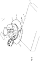
- FIG. 1a shows in a perspective view of an embodiment of this inventively designed Zählusionnvortechnik comprising as essential components a base device 10, which is also referred to in the art as a transfer block and a coaxially aligned to the base device and rotatably arranged counting disc 20.
- the base device 10 is relative to the dial 20 in Operation arranged stationary.
- the vacuum generating device flanged to the base device 10 in the described embodiment for example a vacuum ejector operating according to the Venturi principle or a vacuum pump, is not shown.
- a drive shaft for rotating the counting disc 20 relative to the stationary base means 10 wherein after the assembly, the drive shaft extends through the drive shaft passage 100 of the base means and is rigidly flanged to the counting disc 20.
- the countertop standing base device 10 is not shown counter shaft and the adapter 102nd fixed, the base device is axially spring-loaded against the dial.
- the flanging of the vacuum-generating device, not shown, to the suction air supply takes place via a vacuum connection, also not shown, of the base device.
- Reference numeral 101 denotes a housing section for receiving a control board and terminals for connection to a central controller.
- the counting disc device is initially set up for determining the number of sheets 41 arranged on a sheet-sheet stack 40.
- the counting disc 20 in the embodiment described, three, each by a radially extending, ie running with a radial direction component, opening 203 separate peripheral portions 200a, b, c, each peripheral portion in the direction of rotation D leading tip or nose 201 and an end portion comprising a trailing hold-down 202.
- FIG. 1a indicated perspective view of the counting disc 20 are provided at the top of the respective tip 201 for detecting an operating situation in which a sheet passes over these test holes and covers them.
- the Zählusionnvoriques is as in FIG.
- peripheral portions 200a, b, c on the underside acted upon by a negative pressure bores, whereby the respectively on the underside of the respective peripheral portion 200a, b, c fitting Sheet is sucked so that it can be performed on the leading edge of the subsequent direction of rotation in the peripheral portion 200 b, c, a top side. Further explanations on the functioning of the counting disc are made below with reference to the FIGS. 3a-c ,
- FIG. 1a In addition, a lighting passage 30a and an imaging passage 30b can be seen which, in the described embodiment, extend in sections both in the base device 10 and in the counting disc 20.
- Both the illumination path 30a and the imaging path 30b have an optical series connection of a multiplicity of optical components, wherein for clarity in the illustration according to FIG. 1a has been omitted to specify the attachment of the optical components in the respective sections of the base device 10 and counting disc 10.
- light emitted from a semiconductor laser at a plurality of relative rotational positions between base part 10 and dial 20 is transmitted from the base device to one of the three illumination aisles of the dial and from there to the underside of the dial Counter disc facing surface of a sheet 41 thrown.
- the illumination passage with respect to the design and arrangement of the optical components is designed so that a line-shaped section is illuminated on the sheet 41.
- the light components scattered or reflected by the illumination section enter a receiving path on the underside of the counting disc and are guided via a respective one of the imaging gear sections in the counting disc and the imaging gear section of the base device 10 onto a sensor surface 490 of a camera 500.
- an image of the illuminated section on the sheet takes place via the imaging path on the sensor surface of the camera 500.
- the counting disc for each of the peripheral portions 200 each have an associated illumination passage section and an associated imaging gear section, wherein the illumination passage sections and the imaging passage sections for all peripheral sections of the counting disc in the described embodiment may be identical, in particular may have the same optical elements.
- the illumination portion extending in the base and the imaging portion extending in the base are simultaneously aligned with the respective illumination portion and the respective imaging portion of one of the peripheral portions of the dial, so that a portion of a sheet illuminates linearly and the illuminated sheet portion the sensor surface of the image sensor device can be imaged.
- the linear light portion produced by the illumination passage on the sheet passes over a predetermined portion on the sheet by rotation of the dial to the base, likewise the image of the linear light portion but scaled with the magnification provided by the imaging gear across the sensor surface of the image sensor means running.
- the counting disc device is designed in particular for detecting a code applied to the sheet, for example a 2D coding, which simplifies the processing of the sheets arranged in stack form.
- a code applied to the sheet for example a 2D coding
- the line-shaped illumination section generated on the illumination path on the sheet covers the area code only partially at a given time, wherein by rotating the dial the line-shaped illumination section on the sheet, the area coding within a period of time, which of the dimensions the coding as well as the rotational speed of the counting disc depends, sweeps.
- the Zählinvorsch invention may also be designed to detect a 3D encoding applied to the sheet, the coding can again be a two-dimensional print image, but that is colored here. It can be provided accordingly to use a poly-colored light source and a polychromatic image sensor to detect the color coding.
- FIG. 1 a shows a situation in which the overhead sheet 41 of the sheet sheet stack 40 is sucked on the underside of the peripheral portion 200a by means of negative pressure bores and thus lifted off the stack 40.
- FIG. 1b shows the situation a short time later, after the counting disc 20 is slightly further rotated in the direction of rotation D and the leading tip 201 of the peripheral portion 200b, which follows the peripheral portion 200a in the direction of rotation, is under attack.
- the tip 201 has a slope from the tip so that the blade 41 slides up this slope and covers the three inspection holes 204. This situation is used in a manner to be described in the described embodiment to generate a count signal, so that the number of sheets in the stack 40 can be determined.
- Figure 1c shows the situation a bit later after the next rotation the counting disc 20 based on the situation according to FIG. 1b wherein the sheet 41 now fully rests on the top of the peripheral portion 200b and the underlying sheet in the stack 40 is sucked from the underside of the peripheral portion 200b, so that it can then be subsequently engaged by the leading tip 201 of the peripheral portion 200c.
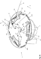
- FIG. 2 shows in a schematic representation of the optical structure of the illumination passage 30a and the imaging passage 30b with their respective optical components, wherein for clarity of illustration, the base device 10 and the counting disc 20 are indicated only by borders, so that the respective illumination aisle and imaging passage sections in the base device and the Counter are recognizable.
- the counting disc 20 has an associated illumination passage section and an associated imaging passage section for completing the illumination passage or the imaging passage.
- FIG. 2 only one of a total of three arranged in the counting device illumination aisle / imaging passage sections in an operating situation in which the passage portions of one of the peripheral portions of the dial 20 are aligned with the passage portions of the base 10.
- the illumination passage section completed as described has, in the described embodiment, a laser diode 300, which is followed by a collimator lens 310.
- the light is deflected by 90 ° by a deflection mirror 320 and passes through a ⁇ / 4 plate 330 aligned with the light, so that the illumination light is thereafter substantially circularly polarized.
- the light passes through two Powell lenses 340a, 340b connected in series, which are rotated 90 ° relative to their optical line crest lines and their complex, two-dimensional aspherical roof design to the asymmetrical luminous surface of the Laser diode are adapted to lower the light density in the central area and increase in the edge area.
- first series connection 350 of two cylindrical lenses and a second series connection 360 of two cylindrical lenses wherein the cylindrical lens pairs are aligned perpendicular to each other as shown in Figure, ie the refractive directions are offset by 90 ° to each other.
- this plane may lie, in particular, in the region of the transition in the base device 10 or the counting disc 20.
- both the base device 10 and the counting device 20 have protective windows in the form of plane-parallel plates 370 and 401 at the end of the respective illumination passage sections. These protective windows close off the illumination and thus protect the optical components against dust and moisture.
- the windows may be made of different materials, e.g. the plate 450 of N-BK7 and the plate 401 due to the contact with the blades in operation of a high hardness optical material, e.g. made of sapphire.
- the light entering the dial 20 is polarized via a polarizer 375 so that the illuminating light transmitted in the dial is linearly polarized.
- the light extending substantially vertically with respect to the optical axis is focused by a mirrored deflecting prism 380, which has a mirrored Hypotenuse surface, 90 °, focused over two cylindrical lenses 390a, 390b and over the Umlenkprisma 400 with mirrored hypotenuse surface the code 45 deflected, so that a line-shaped illumination area on the section 45 is formed.
- the width of the illuminated portion is about 20 microns, while the perpendicular extent of the illumination strip is a few millimeters, in particular about 7 mm.
- the deflecting prism 400 to complete the lighting cycle Protective window in the form of a plane-parallel plate 401, here a sapphire plate specified, which is cemented in the described embodiment of the deflection prism.
- the line-shaped illumination portion on the sheet scatters and / or reflects light, with a portion of this reflected and / or scattered light falling over the sapphire plate 401 back into the deflection prism 400 in the imaging path labeled 30b.
- the imaging path has a first imaging stage, comprising three cylindrical lenses 410a, b, c, which image the line-shaped illumination section on the coding 45 into an intermediate image plane, which in the described embodiment lies in the base device 10.
- the light in the counting disk is first directed upwards in the direction of the base device 10 via a deflection prism 430, which has a mirrored hypotenuse surface, and passes through the polarizer 440, which is arranged directly behind the deflection prism 430 and which is oriented perpendicular to the polarizer 375 with respect to its transmission direction is.
- the light incident on the encoder 45 is polarized perpendicular to the light subsequently transmitted to the polarizer 440.
- the merging image sections of the counter and the base device in the described embodiment are each terminated for protection against contamination and moisture. While this function is provided in the dial 20 by the polarizer 440, the imaging path portion of the base is closed toward the dial by a plane-parallel plate 450, here, N-BK7.
- a field lens 460 is arranged, which images the exit pupil of the first imaging stage in the entrance pupil of a second imaging stage 480.
- this second imaging stage acts as an objective, which images the intermediate image at the location of the ground glass 470 onto a sensor surface 490 of a camera.
- it may also be provided to arrange the ground glass 470 on the field lens 460, in particular to cement it and to place this optical interconnection at the location of the intermediate image.
- the line-shaped illumination section covers only a part of the 2D coding 45 in the described embodiment, this covers the detection plane via the two imaging stages, i. image dropped on the image sensor 490 only covers a portion of the photosensitive surface of the image sensor 490.
- the line-shaped luminous surface on the underside of the dial facing paper side sweeps over the entire coding, so in the same way the imaged on the image sensor illumination section covers the surface of the image sensor 490, so within a predetermined period of time, the entire 2D encoding is imaged on the image sensor 490.
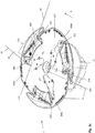
- FIG. 3a shows a perspective bottom view of the Zählusionnvortechnik invention, ie substantially on the underside of the dial 20.
- the peripheral portions 200a, b, c are also visible with respect to their undersides identically constructed.
- each circumferential section is further associated with an optical insert 213 terminating with the underside of the counting disk 20, which is inserted into the counting disk in this peripheral section and has an opening which is closed by the plane-parallel optical disk 401.
- the insert 213 is provided with a reference numeral only for the peripheral portion 200a, while the portions of the suction holes are provided with reference numerals only in the peripheral portion 200c.
- This respective optical insert 213 comprises a support on which the optical components of the respective illumination passage section and the imaging passage section of the counting disc 20, see Fig.
- the drive shaft bushing 214 in the counting disc for receiving the drive shaft, not shown, which is fixedly connected in the assembled state with the rotating to the base device 10 counting disc 20.
- a driver arranged on the drive shaft engages in the driver bore 215.
- the dial may instead of three also fewer or more peripheral portions, for example, four or five, which in turn may be identical and similar to the described embodiment, in particular with three circumferentially spaced portions of suction holes, which between a leading tip 201 and a trailing hold-down 202 may be arranged.
- the count rate can be increased while maintaining the speed of rotation.
- FIG. 3a shows a situation in which the sheet 41, which is opposite to the bottom 40 of the counting disc 20 on the stack 40, was previously sucked by portion 210 of the peripheral portion 200a and then the portion 211 of suction holes is covered and sucked over this, wherein on the sheet applied 2D encoding 45 has not swept the optical disk 401, that is, the code has not yet been detected by the inventively designed Zählinvorraum.
- the end plate 401 provides access to the respective lighting aisle sections and image passage sections that run within the dial, the here respective plane, plane-parallel optical plate 401 in front of the deflection prism 400, see FIG. 2 , that is, the illumination passage section and the imaging passage section in the respective peripheral section 200a, b, c terminates.
- the orientation and arrangement of the optical components is carried out such that the line-shaped illumination section on the blade 41 extends with respect to its longitudinal extent substantially radially to the dial.
- this illumination section runs centrally to the optical plate 401 and extends in the radial direction substantially over its entire optically effective extent.
- the illumination section extends perpendicularly in the radial direction, i. tangential only over a fraction of the extension of the optical disk.
- FIG. 3b shows the operating situation in which the coding, which is formed in the described embodiment as a data matrix code with a surface of 6.5 x 6.5 mm 2 , just within the optical disk 401. At the same time, the sheet 41 is sucked through the suction holes within the sections 211, 212. In the in FIG.
- the 2D encoding 45 is located substantially completely inside the optical disk, even in this situation, only in the area of the center of the optical disk 401 is the area of the coding 45 imaged on the sensor surface 490, so that in the course of scanning the encoding the respective sections are imaged into different areas of the sensor surface, as the imaging gear section in the dial moves relative to the imaging section in the base device.
- Figure 3c shows one in relation to the situation according to FIG. 3b a shortly after operating situation in which the edge 42 of the blade 41 is located just before the leading tip 201 of the section 200b.
- the air intake holes in the section 212 act, so that the sheet is sucked in this area in the groove 205, so that the edge 42 in the direction of the Figure 3c is below the leading tip 201, so that it is received by this and further slides on the tip for covering the scholarlochbohrept 204, see FIG. 1b
- the educalochbohronne are subjected to the vacuum as the suction holes, wherein a clocking of the sheet through the cover retaining negative pressure can be detected in the base device and processed as a count signal from a control device.
- the coupling of the negative pressure i. the Saugluftzu arrangement
- the base device rotating Zählefficiency 20 and the coupling of the illumination light in the respective illumination passage portion of the Zählusion and the image capture in or on the base means in that are provided on the respectively associated end faces of the base means and the counting disc areas for example Suction holes and imaging sections or lighting sections of the counting disc 20 with those of the base device 10 at predetermined times and intermittently to couple.
- This coupling is accomplished by overlapping the respective areas such as holes by the relative rotation of the dial to the base at predetermined times, in the described embodiment the dial rotating at a uniform speed throughout the detection of the sheets of the stack.
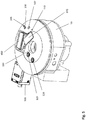
- FIG. 4 shows a with respect to the sheet stack 40 and the dial 20 for Figure 1c identical situation, with the base device removed. As a result, the provided on the upper end face of the dial 20 designs are visible.
- FIG. 4 illustrated situation a situation is shown in which the top sheet 41 of the stack 40 has been picked up by the tip 201 of the peripheral portion 200b and at the top over the scholarlochbohrept 204 slides away, the underlying sheet first on the suction holes of the section 210th (please refer FIG. 3a ) and subsequently sucked by the suction holes of the section 211.
- These suction holes are continued inside the counting disc 20 and end at its end face to the base device 10 in the suction holes 220 for the portion 210 and the suction holes 225 for the section 211.
- both linear polarizers are on the respective optical insert 213, see Fig. 3a , fixed, which is arranged in a corresponding recess in the counting disc 20.
- the peripheral portion indicated by reference numeral 245 includes a plurality of vacuum exhaust holes, which are effective particularly in the region of the groove 205 after the sheet is caught by the tip 201 of the peripheral portion 200c. Rotates the dial 200 from the position according to FIG. 4 Further, the tip 201 of the peripheral portion 200c detects the sheet, which then sweeps across the test hole bores 204 of the peripheral portion 200c to generate a count pulse.
- the test bores 204 are fed in the described embodiment by the radially outer scholarlocheingang 250, which is arranged on the same radial circumferential line as the suction holes 225. Since the count generated by the cover of the striglochbohrungen 204 count is detected in the region of the base device by means of a pressure sensor, not shown , The counting disc also has a test hole output 255 on the end face to the base device.
- each of the three peripheral portions 200a, b, c, the described connections on its front side to the base device, so counted at each peripheral portion of the leaves and on the preceding in the direction of rotation peripheral portion of the mounted on the respective sheet encoding is detected.
- the counting disc in the described embodiment two trigger markers 260, 261, which with on, the Counter disk facing end face of the base device mounted photocells cooperate.
- FIG. 5 now shows that of the dial according to FIG. 4 facing front side of the base device in a perspective view, so that with the reference to FIG. 4 described configurations corresponding configurations are recognizable.
- the suction bore 105 corresponds insofar as a function of the rotational position of the hub with the suction holes 225 and the fürlocheingang 250.
- the suction holes 106 correspond to the suction holes 220 and 240, the scholarlochausgang 255 corresponding to the educalocheingang 110. Also visible are the front ends of the lighting gear section or ., its end plate 370 and the imaging gear section or its end plate 450th
- the base device 10 also has an in FIG. 5 unspecified optical insert on.
- the sleeve comprises a support to which the optical components of the illumination passage section and the imaging passage section of the base device are fastened, wherein the support is inserted into a provided recess of the base device.
- FIG. 5 the two with the trigger markers 260, 261 on the front side of the dial according to FIG. 4 cooperating photocells 125, 126, whose outputs are used to control the image sensor 490.
- trigger markings are not arranged on the counting disc, but on another component which is moved by the drive shaft.
- the counting disc facing end side of the base device has a Running surface for the counting disc from a soft to this material, the optical end plates are deposited on the adjacent end faces of the base device and counting disc respectively to the tread inside, so as not to soil the optical window or even damage.
- the scanning of the coding of the sheets of the stack is not realized on the underside of the counting disk, but on the upper side of the counting disk, ie at the in the FIGS. 1a-c visible end face of the counting disc.
- counting disk as used in this application is to be interpreted generally as meaning a disk (turntable) which rotates relative to the base device and which is designed to differentiate or separate sheets adjacent to one another on the sheet stack, so that on or in the sheets of the sheet Stack codings or features provided optically detected and can be made available for further processing.
Landscapes
- Physics & Mathematics (AREA)
- General Physics & Mathematics (AREA)
- Engineering & Computer Science (AREA)
- Theoretical Computer Science (AREA)
- Length Measuring Devices By Optical Means (AREA)
- Investigating Or Analysing Materials By Optical Means (AREA)
Applications Claiming Priority (1)
| Application Number | Priority Date | Filing Date | Title |
|---|---|---|---|
| DE102016112405.2A DE102016112405B3 (de) | 2016-07-06 | 2016-07-06 | Zählscheibenvorrichtung |
Publications (2)
| Publication Number | Publication Date |
|---|---|
| EP3267367A1 true EP3267367A1 (fr) | 2018-01-10 |
| EP3267367B1 EP3267367B1 (fr) | 2020-05-06 |
Family
ID=59055038
Family Applications (1)
| Application Number | Title | Priority Date | Filing Date |
|---|---|---|---|
| EP17175416.1A Active EP3267367B1 (fr) | 2016-07-06 | 2017-06-12 | Dispositif de disque de comptage |
Country Status (3)
| Country | Link |
|---|---|
| EP (1) | EP3267367B1 (fr) |
| DE (1) | DE102016112405B3 (fr) |
| ES (1) | ES2808303T3 (fr) |
Families Citing this family (3)
| Publication number | Priority date | Publication date | Assignee | Title |
|---|---|---|---|---|
| DE202022104808U1 (de) | 2022-08-25 | 2023-11-30 | Bw Papersystems Hamburg Gmbh | Vorrichtung zum Unterteilen eines Stapels von Blättern in Riese vorgegebener Blattzahl |
| DE102022121537A1 (de) | 2022-08-25 | 2024-03-07 | Bw Papersystems Hamburg Gmbh | Vorrichtung und Verfahren zum Unterteilen eines Stapels von Blättern in Riese vorgegebener Blattzahl |
| WO2024208677A1 (fr) * | 2023-04-06 | 2024-10-10 | Bw Papersystems Stuttgart Gmbh | Appareil et procédé de capture automatique d'informations appliquées à et/ou sur des feuilles dans une pile de feuilles et/ou introduites dans des feuilles |
Citations (4)
| Publication number | Priority date | Publication date | Assignee | Title |
|---|---|---|---|---|
| EP0816554A1 (fr) * | 1996-06-26 | 1998-01-07 | Mahlo GmbH & Co. KG | Procédé et dispositif de correction d'étirage |
| DE19939165A1 (de) * | 1999-08-20 | 2001-03-01 | Koenig & Bauer Ag | Verfahren und eine Vorrichtung zur Verarbeitung von Blättern |
| JP2003288628A (ja) * | 2002-01-28 | 2003-10-10 | Omron Corp | 紙葉類確定装置 |
| US20070206192A1 (en) * | 2006-03-01 | 2007-09-06 | General Electric Company | System and method for multimode imaging |
Family Cites Families (1)
| Publication number | Priority date | Publication date | Assignee | Title |
|---|---|---|---|---|
| DE102007047468A1 (de) * | 2007-09-28 | 2009-04-02 | Carl Zeiss Microimaging Gmbh | Verfahren und Anordnung zur optischen Erfassung einer beleuchteten Probe |
-
2016
- 2016-07-06 DE DE102016112405.2A patent/DE102016112405B3/de active Active
-
2017
- 2017-06-12 ES ES17175416T patent/ES2808303T3/es active Active
- 2017-06-12 EP EP17175416.1A patent/EP3267367B1/fr active Active
Patent Citations (4)
| Publication number | Priority date | Publication date | Assignee | Title |
|---|---|---|---|---|
| EP0816554A1 (fr) * | 1996-06-26 | 1998-01-07 | Mahlo GmbH & Co. KG | Procédé et dispositif de correction d'étirage |
| DE19939165A1 (de) * | 1999-08-20 | 2001-03-01 | Koenig & Bauer Ag | Verfahren und eine Vorrichtung zur Verarbeitung von Blättern |
| JP2003288628A (ja) * | 2002-01-28 | 2003-10-10 | Omron Corp | 紙葉類確定装置 |
| US20070206192A1 (en) * | 2006-03-01 | 2007-09-06 | General Electric Company | System and method for multimode imaging |
Also Published As
| Publication number | Publication date |
|---|---|
| ES2808303T3 (es) | 2021-02-26 |
| DE102016112405B3 (de) | 2017-08-17 |
| EP3267367B1 (fr) | 2020-05-06 |
Similar Documents
| Publication | Publication Date | Title |
|---|---|---|
| DE69703213T2 (de) | Vorrichtung und Verfahren zur Fokusierung eines Laserstrahls für optische Codes | |
| EP2513875B1 (fr) | Spectrodétecteur pour la vérification de documents de valeur | |
| DE3510058C2 (de) | Gerät zum Lesen von Zeichen- und Bildinformationen | |
| DE3609669C2 (fr) | ||
| DE102013003090A1 (de) | Verfahren und Vorrichtung zum Prüfen von Faltzuschnitten | |
| DE102014203645B4 (de) | Verfahren und Vorrichtung zum optischen Bestimmen eines Abstandes | |
| DE3613209A1 (de) | Optische oberflaechenprofil-messeinrichtung | |
| WO2011072862A1 (fr) | Capteur pour vérifier des documents de valeur | |
| EP3528042A1 (fr) | Caméra et procédé de détection des données d'image | |
| EP3267367B1 (fr) | Dispositif de disque de comptage | |
| EP3569976A1 (fr) | Tête de mesure de rugosité, dispositif avec ladite tête de mesure et utilisation correspondante | |
| DD292318A5 (de) | Vorrichtung fuer kontaktlose, raeumliche messungen | |
| EP2513874B1 (fr) | Détecteur pour vérifier des documents de valeur | |
| DE10000030A1 (de) | Kamerasystem für die Bearbeitung von Dokumenten | |
| DE102020113183B4 (de) | Kamera und Verfahren zur Erfassung von bewegten Objekten | |
| DE3242002C2 (fr) | ||
| EP0417042B1 (fr) | Dispositif de balayage photo-électrique | |
| EP1251347B1 (fr) | Dispositif pour le balayage optique d'une bande de matériau défilante et méthode pour sa mise au point | |
| EP0266477A2 (fr) | Dispositif de mesure du couple transmis par un arbre tournant | |
| WO2004029691A1 (fr) | Procede et dispositif pour determiner une distance, module de mise au point automatique, microscope et procede pour la mise au point automatique d'un microscope | |
| WO2009115179A2 (fr) | Appareil de mesure et dispositif de détection de variations de position | |
| EP1223132B1 (fr) | Dispositif optoélectrique | |
| DE2754319C2 (de) | Vorrichtung zum Abtasten von Markierungen an Flaschenhälsen | |
| WO2010049038A1 (fr) | Barrière lumineuse à réflexion avec fonction de mesure de distance et/ou de localisation | |
| EP1622196A1 (fr) | Un appareil pour traiter un wafer et un procédé appartenant |
Legal Events
| Date | Code | Title | Description |
|---|---|---|---|
| PUAI | Public reference made under article 153(3) epc to a published international application that has entered the european phase |
Free format text: ORIGINAL CODE: 0009012 |
|
| STAA | Information on the status of an ep patent application or granted ep patent |
Free format text: STATUS: THE APPLICATION HAS BEEN PUBLISHED |
|
| AK | Designated contracting states |
Kind code of ref document: A1 Designated state(s): AL AT BE BG CH CY CZ DE DK EE ES FI FR GB GR HR HU IE IS IT LI LT LU LV MC MK MT NL NO PL PT RO RS SE SI SK SM TR |
|
| AX | Request for extension of the european patent |
Extension state: BA ME |
|
| STAA | Information on the status of an ep patent application or granted ep patent |
Free format text: STATUS: REQUEST FOR EXAMINATION WAS MADE |
|
| 17P | Request for examination filed |
Effective date: 20180710 |
|
| RBV | Designated contracting states (corrected) |
Designated state(s): AL AT BE BG CH CY CZ DE DK EE ES FI FR GB GR HR HU IE IS IT LI LT LU LV MC MK MT NL NO PL PT RO RS SE SI SK SM TR |
|
| GRAP | Despatch of communication of intention to grant a patent |
Free format text: ORIGINAL CODE: EPIDOSNIGR1 |
|
| STAA | Information on the status of an ep patent application or granted ep patent |
Free format text: STATUS: GRANT OF PATENT IS INTENDED |
|
| INTG | Intention to grant announced |
Effective date: 20200227 |
|
| GRAS | Grant fee paid |
Free format text: ORIGINAL CODE: EPIDOSNIGR3 |
|
| GRAA | (expected) grant |
Free format text: ORIGINAL CODE: 0009210 |
|
| STAA | Information on the status of an ep patent application or granted ep patent |
Free format text: STATUS: THE PATENT HAS BEEN GRANTED |
|
| AK | Designated contracting states |
Kind code of ref document: B1 Designated state(s): AL AT BE BG CH CY CZ DE DK EE ES FI FR GB GR HR HU IE IS IT LI LT LU LV MC MK MT NL NO PL PT RO RS SE SI SK SM TR |
|
| REG | Reference to a national code |
Ref country code: GB Ref legal event code: FG4D Free format text: NOT ENGLISH |
|
| REG | Reference to a national code |
Ref country code: CH Ref legal event code: EP Ref country code: AT Ref legal event code: REF Ref document number: 1267976 Country of ref document: AT Kind code of ref document: T Effective date: 20200515 |
|
| REG | Reference to a national code |
Ref country code: DE Ref legal event code: R096 Ref document number: 502017005113 Country of ref document: DE |
|
| REG | Reference to a national code |
Ref country code: IE Ref legal event code: FG4D Free format text: LANGUAGE OF EP DOCUMENT: GERMAN |
|
| REG | Reference to a national code |
Ref country code: CH Ref legal event code: NV Representative=s name: KATZAROV SA, CH |
|
| REG | Reference to a national code |
Ref country code: LT Ref legal event code: MG4D |
|
| REG | Reference to a national code |
Ref country code: NL Ref legal event code: MP Effective date: 20200506 |
|
| PG25 | Lapsed in a contracting state [announced via postgrant information from national office to epo] |
Ref country code: SE Free format text: LAPSE BECAUSE OF FAILURE TO SUBMIT A TRANSLATION OF THE DESCRIPTION OR TO PAY THE FEE WITHIN THE PRESCRIBED TIME-LIMIT Effective date: 20200506 Ref country code: LT Free format text: LAPSE BECAUSE OF FAILURE TO SUBMIT A TRANSLATION OF THE DESCRIPTION OR TO PAY THE FEE WITHIN THE PRESCRIBED TIME-LIMIT Effective date: 20200506 Ref country code: PT Free format text: LAPSE BECAUSE OF FAILURE TO SUBMIT A TRANSLATION OF THE DESCRIPTION OR TO PAY THE FEE WITHIN THE PRESCRIBED TIME-LIMIT Effective date: 20200907 Ref country code: IS Free format text: LAPSE BECAUSE OF FAILURE TO SUBMIT A TRANSLATION OF THE DESCRIPTION OR TO PAY THE FEE WITHIN THE PRESCRIBED TIME-LIMIT Effective date: 20200906 Ref country code: FI Free format text: LAPSE BECAUSE OF FAILURE TO SUBMIT A TRANSLATION OF THE DESCRIPTION OR TO PAY THE FEE WITHIN THE PRESCRIBED TIME-LIMIT Effective date: 20200506 Ref country code: GR Free format text: LAPSE BECAUSE OF FAILURE TO SUBMIT A TRANSLATION OF THE DESCRIPTION OR TO PAY THE FEE WITHIN THE PRESCRIBED TIME-LIMIT Effective date: 20200807 Ref country code: NO Free format text: LAPSE BECAUSE OF FAILURE TO SUBMIT A TRANSLATION OF THE DESCRIPTION OR TO PAY THE FEE WITHIN THE PRESCRIBED TIME-LIMIT Effective date: 20200806 |
|
| PG25 | Lapsed in a contracting state [announced via postgrant information from national office to epo] |
Ref country code: LV Free format text: LAPSE BECAUSE OF FAILURE TO SUBMIT A TRANSLATION OF THE DESCRIPTION OR TO PAY THE FEE WITHIN THE PRESCRIBED TIME-LIMIT Effective date: 20200506 Ref country code: RS Free format text: LAPSE BECAUSE OF FAILURE TO SUBMIT A TRANSLATION OF THE DESCRIPTION OR TO PAY THE FEE WITHIN THE PRESCRIBED TIME-LIMIT Effective date: 20200506 Ref country code: BG Free format text: LAPSE BECAUSE OF FAILURE TO SUBMIT A TRANSLATION OF THE DESCRIPTION OR TO PAY THE FEE WITHIN THE PRESCRIBED TIME-LIMIT Effective date: 20200806 Ref country code: HR Free format text: LAPSE BECAUSE OF FAILURE TO SUBMIT A TRANSLATION OF THE DESCRIPTION OR TO PAY THE FEE WITHIN THE PRESCRIBED TIME-LIMIT Effective date: 20200506 |
|
| PG25 | Lapsed in a contracting state [announced via postgrant information from national office to epo] |
Ref country code: NL Free format text: LAPSE BECAUSE OF FAILURE TO SUBMIT A TRANSLATION OF THE DESCRIPTION OR TO PAY THE FEE WITHIN THE PRESCRIBED TIME-LIMIT Effective date: 20200506 Ref country code: AL Free format text: LAPSE BECAUSE OF FAILURE TO SUBMIT A TRANSLATION OF THE DESCRIPTION OR TO PAY THE FEE WITHIN THE PRESCRIBED TIME-LIMIT Effective date: 20200506 |
|
| PG25 | Lapsed in a contracting state [announced via postgrant information from national office to epo] |
Ref country code: CZ Free format text: LAPSE BECAUSE OF FAILURE TO SUBMIT A TRANSLATION OF THE DESCRIPTION OR TO PAY THE FEE WITHIN THE PRESCRIBED TIME-LIMIT Effective date: 20200506 Ref country code: RO Free format text: LAPSE BECAUSE OF FAILURE TO SUBMIT A TRANSLATION OF THE DESCRIPTION OR TO PAY THE FEE WITHIN THE PRESCRIBED TIME-LIMIT Effective date: 20200506 Ref country code: SM Free format text: LAPSE BECAUSE OF FAILURE TO SUBMIT A TRANSLATION OF THE DESCRIPTION OR TO PAY THE FEE WITHIN THE PRESCRIBED TIME-LIMIT Effective date: 20200506 Ref country code: EE Free format text: LAPSE BECAUSE OF FAILURE TO SUBMIT A TRANSLATION OF THE DESCRIPTION OR TO PAY THE FEE WITHIN THE PRESCRIBED TIME-LIMIT Effective date: 20200506 Ref country code: DK Free format text: LAPSE BECAUSE OF FAILURE TO SUBMIT A TRANSLATION OF THE DESCRIPTION OR TO PAY THE FEE WITHIN THE PRESCRIBED TIME-LIMIT Effective date: 20200506 |
|
| REG | Reference to a national code |
Ref country code: DE Ref legal event code: R097 Ref document number: 502017005113 Country of ref document: DE |
|
| PG25 | Lapsed in a contracting state [announced via postgrant information from national office to epo] |
Ref country code: SK Free format text: LAPSE BECAUSE OF FAILURE TO SUBMIT A TRANSLATION OF THE DESCRIPTION OR TO PAY THE FEE WITHIN THE PRESCRIBED TIME-LIMIT Effective date: 20200506 Ref country code: MC Free format text: LAPSE BECAUSE OF FAILURE TO SUBMIT A TRANSLATION OF THE DESCRIPTION OR TO PAY THE FEE WITHIN THE PRESCRIBED TIME-LIMIT Effective date: 20200506 Ref country code: PL Free format text: LAPSE BECAUSE OF FAILURE TO SUBMIT A TRANSLATION OF THE DESCRIPTION OR TO PAY THE FEE WITHIN THE PRESCRIBED TIME-LIMIT Effective date: 20200506 |
|
| REG | Reference to a national code |
Ref country code: ES Ref legal event code: FG2A Ref document number: 2808303 Country of ref document: ES Kind code of ref document: T3 Effective date: 20210226 |
|
| PLBE | No opposition filed within time limit |
Free format text: ORIGINAL CODE: 0009261 |
|
| STAA | Information on the status of an ep patent application or granted ep patent |
Free format text: STATUS: NO OPPOSITION FILED WITHIN TIME LIMIT |
|
| PG25 | Lapsed in a contracting state [announced via postgrant information from national office to epo] |
Ref country code: LU Free format text: LAPSE BECAUSE OF NON-PAYMENT OF DUE FEES Effective date: 20200612 |
|
| 26N | No opposition filed |
Effective date: 20210209 |
|
| REG | Reference to a national code |
Ref country code: BE Ref legal event code: MM Effective date: 20200630 |
|
| PG25 | Lapsed in a contracting state [announced via postgrant information from national office to epo] |
Ref country code: IE Free format text: LAPSE BECAUSE OF NON-PAYMENT OF DUE FEES Effective date: 20200612 |
|
| PG25 | Lapsed in a contracting state [announced via postgrant information from national office to epo] |
Ref country code: SI Free format text: LAPSE BECAUSE OF FAILURE TO SUBMIT A TRANSLATION OF THE DESCRIPTION OR TO PAY THE FEE WITHIN THE PRESCRIBED TIME-LIMIT Effective date: 20200506 Ref country code: BE Free format text: LAPSE BECAUSE OF NON-PAYMENT OF DUE FEES Effective date: 20200630 |
|
| PG25 | Lapsed in a contracting state [announced via postgrant information from national office to epo] |
Ref country code: TR Free format text: LAPSE BECAUSE OF FAILURE TO SUBMIT A TRANSLATION OF THE DESCRIPTION OR TO PAY THE FEE WITHIN THE PRESCRIBED TIME-LIMIT Effective date: 20200506 Ref country code: MT Free format text: LAPSE BECAUSE OF FAILURE TO SUBMIT A TRANSLATION OF THE DESCRIPTION OR TO PAY THE FEE WITHIN THE PRESCRIBED TIME-LIMIT Effective date: 20200506 Ref country code: CY Free format text: LAPSE BECAUSE OF FAILURE TO SUBMIT A TRANSLATION OF THE DESCRIPTION OR TO PAY THE FEE WITHIN THE PRESCRIBED TIME-LIMIT Effective date: 20200506 |
|
| PG25 | Lapsed in a contracting state [announced via postgrant information from national office to epo] |
Ref country code: MK Free format text: LAPSE BECAUSE OF FAILURE TO SUBMIT A TRANSLATION OF THE DESCRIPTION OR TO PAY THE FEE WITHIN THE PRESCRIBED TIME-LIMIT Effective date: 20200506 |
|
| PGFP | Annual fee paid to national office [announced via postgrant information from national office to epo] |
Ref country code: GB Payment date: 20250620 Year of fee payment: 9 |
|
| PGFP | Annual fee paid to national office [announced via postgrant information from national office to epo] |
Ref country code: FR Payment date: 20250626 Year of fee payment: 9 |
|
| PGFP | Annual fee paid to national office [announced via postgrant information from national office to epo] |
Ref country code: AT Payment date: 20250616 Year of fee payment: 9 |
|
| PGFP | Annual fee paid to national office [announced via postgrant information from national office to epo] |
Ref country code: ES Payment date: 20250718 Year of fee payment: 9 |
|
| PGFP | Annual fee paid to national office [announced via postgrant information from national office to epo] |
Ref country code: DE Payment date: 20250829 Year of fee payment: 9 |
|
| PGFP | Annual fee paid to national office [announced via postgrant information from national office to epo] |
Ref country code: IT Payment date: 20250630 Year of fee payment: 9 |
|
| PGFP | Annual fee paid to national office [announced via postgrant information from national office to epo] |
Ref country code: CH Payment date: 20250701 Year of fee payment: 9 |