EP3267448A1 - Dispositif d'isolation supplémentaire permettant de faire fonctionner à distance un disjoncteur pour équipement électrique - Google Patents
Dispositif d'isolation supplémentaire permettant de faire fonctionner à distance un disjoncteur pour équipement électrique Download PDFInfo
- Publication number
- EP3267448A1 EP3267448A1 EP16178544.9A EP16178544A EP3267448A1 EP 3267448 A1 EP3267448 A1 EP 3267448A1 EP 16178544 A EP16178544 A EP 16178544A EP 3267448 A1 EP3267448 A1 EP 3267448A1
- Authority
- EP
- European Patent Office
- Prior art keywords
- circuit breaker
- electrical
- isolating device
- coil
- control voltage
- Prior art date
- Legal status (The legal status is an assumption and is not a legal conclusion. Google has not performed a legal analysis and makes no representation as to the accuracy of the status listed.)
- Withdrawn
Links
- 230000000007 visual effect Effects 0.000 claims description 3
- 230000004224 protection Effects 0.000 description 6
- 238000000034 method Methods 0.000 description 4
- 238000012423 maintenance Methods 0.000 description 3
- 238000002955 isolation Methods 0.000 description 2
- 229910000831 Steel Inorganic materials 0.000 description 1
- 238000010586 diagram Methods 0.000 description 1
- 229910001220 stainless steel Inorganic materials 0.000 description 1
- 239000010935 stainless steel Substances 0.000 description 1
- 239000010959 steel Substances 0.000 description 1
- 239000013589 supplement Substances 0.000 description 1
Images

Classifications
-
- H—ELECTRICITY
- H01—ELECTRIC ELEMENTS
- H01H—ELECTRIC SWITCHES; RELAYS; SELECTORS; EMERGENCY PROTECTIVE DEVICES
- H01H9/00—Details of switching devices, not covered by groups H01H1/00 - H01H7/00
- H01H9/20—Interlocking, locking, or latching mechanisms
- H01H9/26—Interlocking, locking, or latching mechanisms for interlocking two or more switches
-
- H—ELECTRICITY
- H01—ELECTRIC ELEMENTS
- H01H—ELECTRIC SWITCHES; RELAYS; SELECTORS; EMERGENCY PROTECTIVE DEVICES
- H01H3/00—Mechanisms for operating contacts
- H01H3/02—Operating parts, i.e. for operating driving mechanism by a mechanical force external to the switch
-
- H—ELECTRICITY
- H01—ELECTRIC ELEMENTS
- H01H—ELECTRIC SWITCHES; RELAYS; SELECTORS; EMERGENCY PROTECTIVE DEVICES
- H01H71/00—Details of the protective switches or relays covered by groups H01H73/00 - H01H83/00
- H01H71/04—Means for indicating condition of the switching device
-
- H—ELECTRICITY
- H01—ELECTRIC ELEMENTS
- H01H—ELECTRIC SWITCHES; RELAYS; SELECTORS; EMERGENCY PROTECTIVE DEVICES
- H01H71/00—Details of the protective switches or relays covered by groups H01H73/00 - H01H83/00
- H01H71/08—Terminals; Connections
-
- H—ELECTRICITY
- H01—ELECTRIC ELEMENTS
- H01H—ELECTRIC SWITCHES; RELAYS; SELECTORS; EMERGENCY PROTECTIVE DEVICES
- H01H71/00—Details of the protective switches or relays covered by groups H01H73/00 - H01H83/00
- H01H71/10—Operating or release mechanisms
-
- H—ELECTRICITY
- H01—ELECTRIC ELEMENTS
- H01H—ELECTRIC SWITCHES; RELAYS; SELECTORS; EMERGENCY PROTECTIVE DEVICES
- H01H71/00—Details of the protective switches or relays covered by groups H01H73/00 - H01H83/00
- H01H71/08—Terminals; Connections
- H01H2071/086—Low power connections for auxiliary switches, e.g. shunt trip
-
- H—ELECTRICITY
- H01—ELECTRIC ELEMENTS
- H01H—ELECTRIC SWITCHES; RELAYS; SELECTORS; EMERGENCY PROTECTIVE DEVICES
- H01H7/00—Devices for introducing a predetermined time delay between the initiation of the switching operation and the opening or closing of the contacts
-
- H—ELECTRICITY
- H01—ELECTRIC ELEMENTS
- H01H—ELECTRIC SWITCHES; RELAYS; SELECTORS; EMERGENCY PROTECTIVE DEVICES
- H01H83/00—Protective switches, e.g. circuit-breaking switches, or protective relays operated by abnormal electrical conditions otherwise than solely by excess current
- H01H83/12—Protective switches, e.g. circuit-breaking switches, or protective relays operated by abnormal electrical conditions otherwise than solely by excess current operated by voltage falling below a predetermined value, e.g. for no-volt protection
-
- H—ELECTRICITY
- H01—ELECTRIC ELEMENTS
- H01H—ELECTRIC SWITCHES; RELAYS; SELECTORS; EMERGENCY PROTECTIVE DEVICES
- H01H9/00—Details of switching devices, not covered by groups H01H1/00 - H01H7/00
- H01H9/16—Indicators for switching condition, e.g. "on" or "off"
-
- H—ELECTRICITY
- H01—ELECTRIC ELEMENTS
- H01H—ELECTRIC SWITCHES; RELAYS; SELECTORS; EMERGENCY PROTECTIVE DEVICES
- H01H9/00—Details of switching devices, not covered by groups H01H1/00 - H01H7/00
- H01H9/20—Interlocking, locking, or latching mechanisms
- H01H9/28—Interlocking, locking, or latching mechanisms for locking switch parts by a key or equivalent removable member
- H01H9/281—Interlocking, locking, or latching mechanisms for locking switch parts by a key or equivalent removable member making use of a padlock
Definitions
- the present disclosure generally relates to an isolating device for lockout-tagout operation of electrical equipment.
- Such equipment is usually located in a locked electrical room where a specified lockout-tagout procedure (LOTO) for isolation, i.e. electrical disconnect, has to be performed. Often specialized personnel have to be sent for to perform this procedure.
- LOTO lockout-tagout procedure
- US 2009/0322083 discloses an integrated fault and personnel protection system for a multi-thread converter in a wind turbine power system.
- An aim of this document is to provide personnel protection during fault conditions and during maintenance. Sensors and disconnects for the protections are positioned close to the source of energy to protect more of the system. Components are moved into separate physical structures, e.g. cabinets, to enhance protection. At least one motor-operated breaker may be positioned between the converter and the generator. The motor-operated circuit breakers may also be tripped by a remote switch located in the tower lower level to provide for lockout-tagout protection.
- the motor-operated circuit breakers disclosed in US 2009/0322083 are connected between the converter and the generator and is specifically a generator type of configuration.
- the remote switch operates a circuit breaker at tower lower level. Furthermore, the remote switch trips the motor-operated circuit breaker directly on the undervoltage coil. This indicates a solution where tripping is made under load.
- an object of the present disclosure is to provide an isolating device for operating a circuit breaker, which solves or at least mitigates problems of the prior art.
- a supplementary isolating device for remote operation of a circuit breaker with interlocking functionality
- the supplementary isolating device comprises: an electrical disconnection switch manoeuvrable between a mechanically lockable first position and a mechanically lockable second position, which electrical disconnection switch is configured to be connected in the control circuit for a circuit breaker of an electrical drive system, wherein the supplementary isolating device is configured to send a first control voltage to the circuit breaker to provide an electrical disconnect and interlocking the operation of the circuit breaker, when the electrical disconnection switch is in the first position, an electric terminal configured to be connected to an auxiliary contact of the circuit breaker to obtain an operational status of the circuit breaker, and an indicator configured to indicate the operational status of the circuit breaker.
- the supplementary isolating device is essentially a duplication of the local isolating function of the circuit breaker, located in an electrical room or area.
- the location of the supplementary isolating device can be flexibly chosen as it is designed for easily installed control cabling, but the device is intended to be installed at a site remote from the electrical room or area, advantageously close to motor or machinery. This enables simple access for an operator to perform a LOTO operation conveniently in the vicinity of the machinery, i.e. remotely from the electrical room or area with the electrical supply equipment which may be located hundreds of metres from machinery and may require passing an environment that is difficult to and/or time consuming to manoeuvre through.
- the supplementary isolating device may therefore conveniently be installed at essentially any suitable location advantageously chosen near a motor or machinery.
- the electrical disconnection switch is lockable in two positions, thus ensuring that it is only operated when sending control voltages to the circuit breaker for operation thereof.
- the electrical disconnection switch can be locked in the first position, i.e. in a position which provides an electrical disconnect of the circuit breaker, allowing the operator to confidently work on the machine, including the electrical equipment.
- Auxiliary contacts of a circuit breaker are configured to provide a signal regarding the operational status of the circuit breaker.
- the indicator and the electric terminal which is connectable to the auxiliary contact of the circuit breaker, ensures that personnel handling the supplementary isolating device is always informed of the current operational status of the circuit breaker.
- the supplementary isolating device is configured to send a second control voltage to the circuit breaker to close the circuit breaker when the electrical disconnection switch is in the second position.
- the electrical disconnection switch is configured to be locked in the first position and in the second position by means of a padlock. It may thereby be ensured that no electrical disconnect can be performed unless the padlock is removed when the electrical disconnection switch is arranged in the second position.
- the indicator is a visual indicator. This essentially fulfils a requirement set forth in standard IEC 60204-1, and ensures that an operator is able to identify whether there is an electrical disconnect present or not.
- One embodiment comprises a first switch terminal configured to be connected to an opening coil and to an undervoltage coil of the control circuit for providing the first control voltage, and a second switch terminal configured to be connected to a closing coil of the control circuit for providing the second control voltage.
- One embodiment comprises a first low voltage electric wire and a second low voltage electric wire each having a length in the order of a plurality of metres, the first electric wire and the second electric wire being configured to be connected between the electrical disconnection switch and the control circuit of the circuit breaker to send the first control voltage and the second control voltage, respectively, from the supplementary isolating device to the control circuit.
- each of the first low voltage electric wire and the second low voltage wire has a length in the order of a plurality of metres.
- One embodiment comprises a signal cable having a length in the order of a plurality of metres, the signal cable being configured to be connected between the electric terminal and the auxiliary contact to obtain the operational status of the circuit breaker.
- an electrical system for a motor comprising: an electrical drive system configured to drive the motor, a circuit breaker with interlocking functionality, wherein the circuit breaker is configured to disconnect the electrical drive system from a power source configured to power the electrical drive system, and a supplementary isolating device according to the first aspect disclosed herein, configured to operate the circuit breaker from a remote location relative to the circuit breaker and the electrical drive system.
- the circuit breaker comprises a first button, a second button, an opening coil, an undervoltage coil, and a closing coil, wherein the first button is configured to operate only the opening coil and the second button is configured to operate only the closing coil.
- the opening coil is configured to be operated with the first control voltage from the supplementary isolating device to provide an electrical disconnect of the circuit breaker
- the closing coil being configured to be operated with the second control voltage from the supplementary isolating device to provide a closing of the circuit breaker
- the undervoltage coil is configured to be operated by the first control voltage to disconnect the opening coil from the first button and to disconnect the closing coil from the second button and to be operated by the second control voltage to connect the closing coil to the first button and the opening coil to the second button.
- One embodiment comprises a time delay device configured to be connected to the control circuit of the circuit breaker, and configured to be connected to the supplementary isolating device for receiving the first control voltage and the second control voltage and to operate the opening coil and the undervoltage coil, and the closing coil, of the control circuit in accordance with the first control voltage and the second control voltage.
- the time delay device has a delay functionality configured to provide a delay from receiving the first control voltage to operating the opening coil, wherein the time delay device is configured to operate the undervoltage coil after operating the opening coil.
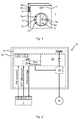
- Fig. 1 shows an example of a supplementary isolating device 1.
- supplementary is here meant that it supplements, or is secondary to, a local isolating function already present in a circuit breaker, for locally operating the circuit breaker, specifically a circuit breaker with interlocking functionality.
- interlocking functionality is meant a certain type of circuit breaker which has an inherent property of interlocking the circuit breaker in a state of electrical disconnect, as will be described in more detail in the following.
- the supplementary isolating device 1 is configured to be remotely connected to and remotely operate a circuit breaker of an electrical drive system, by means of control voltages, which circuit breaker is provided with interlocking functionality.
- the supplementary isolating device 1 is thus adapted and configured to be installed at a remote site relative to the circuit breaker.
- the circuit breaker is generally provided in an electrical room or area comprising one or more electrical cabinets including equipment such as an electrical drive system for driving motors of machinery of for example a process industry such as a pulp and paper mill or a steel mill.
- the supplementary isolating device 1 may advantageously be installed at a convenient location, in the proximity of the machinery, e.g. a paper machine, pulp refiners, stainless steel grinding lines, and so on, driven by motors to allow easy access to a LOTO operation for the operator or other maintenance personnel.
- the supplementary isolating device 1 may for example be installed next to a specific motor that is to be isolated, in order to reduce the risk of confusion as to what machinery is isolated by the supplementary isolating device 1.
- the exemplified supplementary isolating device 1 comprises an enclosure or housing 3 and an electrical disconnection switch 5 which is accessible externally relative to the housing 3.
- the electrical disconnection switch 5 is manoeuvrable between a first position and a second position.
- the electrical disconnection switch 5 is furthermore mechanically lockable in the first position and in the second position.
- the electrical disconnection switch 5 is locked in the first position, it is not possible to manoeuvre the electrical disconnection switch 5 to the second position.
- the electrical disconnection switch 5 is locked in the second position, i.e. it is in this case not possible to manoeuvre the electrical disconnection switch 5 to the first position.
- the electrical disconnection switch 5 is rotatable between the first position and the second position.
- the exemplified electrical disconnection switch 5 has a cut-out or through-opening 5a
- the supplementary isolating device 1 has a circular collar 7 arranged around the electrical disconnection switch 5.
- the collar 7 is provided with a plurality of through-openings 7a, which when aligned with the cut-out 5a allows for mounting of the shackle of a padlock to thereby ensure mechanical locking of the electrical disconnection switch 5.
- One through-opening 7a of the collar 7 and the cut-out 5a are so arranged that they become aligned when the electrical disconnection switch 5 is in the first position and another through-opening 7a of the collar 7 is so arranged that it becomes aligned with the cut-out 5a when the electrical disconnection switch 5 is in the second position. It is to be noted that other physical configurations of the electrical disconnection switch and the mechanical locking thereof are also possible, as would be apparent to the person skilled in the art.
- the electrical disconnection switch 5 is configured to be connected to the control circuit of a circuit breaker having interlocking functionality.
- the electrical disconnection switch 5 may either be connected directly to the control circuit, or indirectly via a time delay device, as will be elaborated upon in the following.
- the supplementary isolating device 1 When the electrical disconnection switch 5 is in the first position, the supplementary isolating device 1 is configured to send a first control voltage to the circuit breaker to provide an electrical disconnect and interlocking the operation of the circuit breaker. When the electrical disconnection switch 5 is in the second position, the supplementary isolating device 1 is configured to send a second control voltage to the circuit breaker to close the circuit breaker.
- the supplementary isolating device 1 also includes an electrical terminal 9 configured to be connected to an auxiliary contact of a circuit breaker to obtain an operational status of the circuit breaker, and an indicator 11 operatively connected to the electrical terminal 9, and configured to indicate the operational status of the circuit breaker as received by the electrical terminal 9.
- the auxiliary contact provides an acknowledgement to the supplementary isolating device 1 regarding a status change of the circuit breaker obtained by manoeuvring the electrical disconnection switch 5.
- the indicator 11 is preferably a visual indicator.
- the indicator 11 may for example be a lamp or a light emitting diode (LED).
- the electrical system 10 comprises the supplementary isolating device 1, a circuit breaker 13 having a control circuit 13a and a local isolating function including a first button 21 and a second button 23, an electrical drive system 15, configured to be connected to the control circuit of the circuit breaker 13.
- an electrical room or area 12 is symbolically shown by the rectangle that encloses the circuit breaker 13 and the electrical drive system 15.
- the dashed line enclosed by the electrical room 12 symbolises one or more electrical cabinet(s) 14 located in the electrical room 12 and which contain(s) the circuit breaker 13 and the electrical drive system 15.
- the electrical drive system 15 is configured to be connected to a motor M located outside the electrical room or area 12, which in turn powers machinery, for example process industry machinery.
- the supplementary isolating device 1 has a first switch terminal 4a and a second switch terminal 4b, as also shown in Fig. 1 . These are configured to be connected to the control circuit 13a of the circuit breaker 13.
- the first switch terminal 4a is configured to provide the first control voltage to the control circuit 13a and the second switch terminal 4b is configured to provide the second control voltage to the control circuit 13a.
- the first control voltage is configured to provide an electrical disconnect, or set the circuit breaker 13 in an open state.
- the first control voltage is furthermore configured to provide an interlocking of the circuit breaker 13.
- the first switch terminal 4a is configured to be connected to an opening coil and to an undervoltage coil of the circuit breaker 13, in particular of the control circuit 13a thereof.
- the second control voltage is configured to set the circuit breaker 13 in a closed state.
- the second switch terminal 4b is thus configured to be connected to a closing coil of the circuit breaker 13, in particular of the control circuit 13a thereof.
- the first switch terminal 4a may be connected to the control circuit 13a by means of a first electric wire which preferably has a length of a plurality of metres, typically several tens of metres or even hundreds of metres.
- the second switch terminal 4b may be connected to the control circuit 13a by means of a second electric wire which preferably has a length of a plurality of metres, typically several tens of metres or even hundreds of metres.
- the supplementary isolating device 1 may be installed remotely from the electrical room 12, preferably in the proximity of the motor M which it is configured to disconnect/isolate, as symbolically illustrated in Fig. 2 .
- a signal cable having a length in the order of a plurality of metres, typically several tens of metres or hundreds of metres, may be connected between the electrical terminal 9 and the auxiliary contact to obtain the operational status of the circuit breaker 13.
- the first button 21 of the circuit breaker 13 is configured to operate the opening coil to provide an electrical disconnect of the circuit breaker 13, i.e. to set the circuit breaker in its open state, and a second button 23 configured to operate the closing coil, i.e. to set the circuit breaker in its closed state.
- the first button 21 and the second button 23 are not connected or connectable to the undervoltage coil.
- the local isolating function hence has no means for operating the undervoltage coil.
- the local isolating function is only able to operate the circuit breaker i.e. to provide both an electrical disconnect of the circuit breaker 13 and to close the circuit breaker, when circuit breaker 13 has been operated locally by the local isolating function.
- the electrical system 10 may furthermore optionally comprise a time delay device 19 such as a safety relay.
- the time delay device 19 is configured to be connected between the control circuit 13a of the circuit breaker 13 and the supplementary isolating device 1.
- the time delay device 19 comprises hardware-coded processing circuitry or processing circuitry comprising software, or a combination of both, configured to provide a control signal to the control system which is configured to control the electrical drive system 15 to reduce the current to the motor M, in case the motor M is in operation when the electrical disconnection switch 5 is set in the first position thus providing an electrical disconnect of the circuit breaker 13.
- the time delay device 19 may furthermore comprise delay-circuitry configured to provide a delay from the time when the time delay device 19 obtains the first control signal until it operates the opening coil to provide an electrical disconnect of the circuit breaker, and furthermore to operate the undervoltage coil only after the opening coil has been operated, to obtain interlocking of the operation of the circuit breaker 13.
- Fig. 3 shows the general operation of the supplementary isolating device 1 in the electrical system 10.
- the upper contact shown in the supplementary isolating device 1 when closed, symbolises that the electrical disconnection switch 5 is in the second position.
- the lower contact shown in the supplementary isolating device 1 when closed, symbolises that the disconnection switch 5 is in the first position.
- the electrical disconnection switch 5 when the electrical disconnection switch 5 is set in the first position, the upper contact will be open and the lower contact will be closed.
- the first control voltage will then be sent to the control circuit 13a of the circuit breaker 13, in this case via the time delay device 19.
- the time delay device 19 will in this case provide a delay before the first control voltage is allowed to operate the opening coil YO of the control circuit 13a.
- the time delay device 19 sends a control signal to the control system in case the motor M is in operation. The delay allows for the electrical drive system 15 to reduce the current to the motor M before providing an electrical disconnect.
- the time delay device 19 will provide the first control voltage to the undervoltage coil YU, which is then de-energised, whereby the two contacts C 1 and C 2 are operated, thus disconnecting the first button 21 and the second button 23, respectively, from the opening coil YO and the closing coil YC.
- This is symbolically illustrated by the two contacts C 1 and C 2 also being shown adjacent to the undervoltage coil YU.
- the circuit breaker 13 is thereby set in its interlocked state.
- the auxiliary contact(s) send(s) an acknowledgement, for status indication, to the supplementary isolating device 1 as the contact C 3 is closed also due to the first control voltage. In this situation, it is not possible to operate the circuit breaker 13 by means of the local isolating function.
- the time delay device 19 may include logic which provides the function that the acknowledgement from the auxiliary contact(s) is only sent to the supplementary isolating device 1 if the opening coil YO has been operated by the first control voltage and the undervoltage coil YU is in a discharged state.
- the indicator 11 will only indicate that the circuit breaker 13 is in the open state if the electrical disconnect has been provided from the supplementary isolating device 1.
- the supplementary isolating device 1 duplicates the behaviour of the local isolating function, but also provides protection from operation of the first button 21 and the second button 23 when the circuit breaker 13 is operated by the supplementary isolating device 1.
Landscapes
- Physics & Mathematics (AREA)
- Electromagnetism (AREA)
- Driving Mechanisms And Operating Circuits Of Arc-Extinguishing High-Tension Switches (AREA)
Priority Applications (8)
| Application Number | Priority Date | Filing Date | Title |
|---|---|---|---|
| EP16178544.9A EP3267448A1 (fr) | 2016-07-08 | 2016-07-08 | Dispositif d'isolation supplémentaire permettant de faire fonctionner à distance un disjoncteur pour équipement électrique |
| CA3030190A CA3030190C (fr) | 2016-07-08 | 2017-05-31 | Dispositif d'isolation complementaire pour la manuvre a distance d'un disjoncteur pour equipement electrique |
| US16/316,238 US10879018B2 (en) | 2016-07-08 | 2017-05-31 | Supplementary isolating device for remote operation of a circuit breaker for electrical equipment |
| ES17730414T ES2812333T3 (es) | 2016-07-08 | 2017-05-31 | Dispositivo de aislamiento suplementario para operación remota de un disyuntor de circuito para equipo eléctrico |
| CN201780042361.4A CN109416986B (zh) | 2016-07-08 | 2017-05-31 | 用于电气装备的断路器的远程操作的补充隔离设备 |
| PCT/EP2017/063083 WO2018007070A1 (fr) | 2016-07-08 | 2017-05-31 | Dispositif d'isolation complémentaire pour la manœuvre à distance d'un disjoncteur pour équipement électrique |
| PL17730414T PL3482406T3 (pl) | 2016-07-08 | 2017-05-31 | Uzupełniające urządzenie izolujące do zdalnej obsługi wyłącznika nadprądowego dla urządzeń elektrycznych |
| EP17730414.4A EP3482406B1 (fr) | 2016-07-08 | 2017-05-31 | Dispositif d'isolation supplémentaire permettant de faire fonctionner à distance un disjoncteur pour équipement électrique |
Applications Claiming Priority (1)
| Application Number | Priority Date | Filing Date | Title |
|---|---|---|---|
| EP16178544.9A EP3267448A1 (fr) | 2016-07-08 | 2016-07-08 | Dispositif d'isolation supplémentaire permettant de faire fonctionner à distance un disjoncteur pour équipement électrique |
Publications (1)
| Publication Number | Publication Date |
|---|---|
| EP3267448A1 true EP3267448A1 (fr) | 2018-01-10 |
Family
ID=56557472
Family Applications (2)
| Application Number | Title | Priority Date | Filing Date |
|---|---|---|---|
| EP16178544.9A Withdrawn EP3267448A1 (fr) | 2016-07-08 | 2016-07-08 | Dispositif d'isolation supplémentaire permettant de faire fonctionner à distance un disjoncteur pour équipement électrique |
| EP17730414.4A Active EP3482406B1 (fr) | 2016-07-08 | 2017-05-31 | Dispositif d'isolation supplémentaire permettant de faire fonctionner à distance un disjoncteur pour équipement électrique |
Family Applications After (1)
| Application Number | Title | Priority Date | Filing Date |
|---|---|---|---|
| EP17730414.4A Active EP3482406B1 (fr) | 2016-07-08 | 2017-05-31 | Dispositif d'isolation supplémentaire permettant de faire fonctionner à distance un disjoncteur pour équipement électrique |
Country Status (7)
| Country | Link |
|---|---|
| US (1) | US10879018B2 (fr) |
| EP (2) | EP3267448A1 (fr) |
| CN (1) | CN109416986B (fr) |
| CA (1) | CA3030190C (fr) |
| ES (1) | ES2812333T3 (fr) |
| PL (1) | PL3482406T3 (fr) |
| WO (1) | WO2018007070A1 (fr) |
Families Citing this family (1)
| Publication number | Priority date | Publication date | Assignee | Title |
|---|---|---|---|---|
| US12051556B2 (en) * | 2019-08-02 | 2024-07-30 | Hollymatic Corporation | Lock out and tag out control system and method |
Citations (4)
| Publication number | Priority date | Publication date | Assignee | Title |
|---|---|---|---|---|
| US4623859A (en) * | 1985-08-13 | 1986-11-18 | Square D Company | Remote control circuit breaker |
| US8896162B1 (en) * | 2010-05-21 | 2014-11-25 | Finley Lee Ledbetter | Device for installing and/or removing components from electrical equipment |
| US20140376142A1 (en) * | 2013-06-25 | 2014-12-25 | Eaton Corporation | Fuse assembly including relay and string including the same |
| DE102013112570A1 (de) * | 2013-11-14 | 2015-05-21 | Eaton Electrical Ip Gmbh & Co. Kg | Vorrichtung zum Betätigen eines in einem Schaltschrank befindlichen Schaltgeräts |
Family Cites Families (4)
| Publication number | Priority date | Publication date | Assignee | Title |
|---|---|---|---|---|
| US11404233B2 (en) * | 2004-09-13 | 2022-08-02 | Eaton Intelligent Power Limited | Fusible switching disconnect modules and devices with tripping coil |
| US7944068B2 (en) | 2008-06-30 | 2011-05-17 | General Electric Company | Optimizing converter protection for wind turbine generators |
| US8410389B2 (en) * | 2009-12-29 | 2013-04-02 | Schneider Electric USA, Inc. | Remote drive for disconnector/isolator used in switchgear |
| US9772381B2 (en) * | 2014-11-06 | 2017-09-26 | Rockwell Automation Technologies, Inc. | Synchronized reapplication of power for driving an electric motor |
-
2016
- 2016-07-08 EP EP16178544.9A patent/EP3267448A1/fr not_active Withdrawn
-
2017
- 2017-05-31 CA CA3030190A patent/CA3030190C/fr active Active
- 2017-05-31 CN CN201780042361.4A patent/CN109416986B/zh active Active
- 2017-05-31 EP EP17730414.4A patent/EP3482406B1/fr active Active
- 2017-05-31 WO PCT/EP2017/063083 patent/WO2018007070A1/fr not_active Ceased
- 2017-05-31 ES ES17730414T patent/ES2812333T3/es active Active
- 2017-05-31 PL PL17730414T patent/PL3482406T3/pl unknown
- 2017-05-31 US US16/316,238 patent/US10879018B2/en active Active
Patent Citations (4)
| Publication number | Priority date | Publication date | Assignee | Title |
|---|---|---|---|---|
| US4623859A (en) * | 1985-08-13 | 1986-11-18 | Square D Company | Remote control circuit breaker |
| US8896162B1 (en) * | 2010-05-21 | 2014-11-25 | Finley Lee Ledbetter | Device for installing and/or removing components from electrical equipment |
| US20140376142A1 (en) * | 2013-06-25 | 2014-12-25 | Eaton Corporation | Fuse assembly including relay and string including the same |
| DE102013112570A1 (de) * | 2013-11-14 | 2015-05-21 | Eaton Electrical Ip Gmbh & Co. Kg | Vorrichtung zum Betätigen eines in einem Schaltschrank befindlichen Schaltgeräts |
Also Published As
| Publication number | Publication date |
|---|---|
| CN109416986A (zh) | 2019-03-01 |
| WO2018007070A1 (fr) | 2018-01-11 |
| US20200227215A1 (en) | 2020-07-16 |
| CA3030190A1 (fr) | 2018-01-11 |
| ES2812333T3 (es) | 2021-03-16 |
| CN109416986B (zh) | 2020-07-14 |
| CA3030190C (fr) | 2019-10-01 |
| PL3482406T3 (pl) | 2021-02-08 |
| EP3482406B1 (fr) | 2020-07-01 |
| US10879018B2 (en) | 2020-12-29 |
| EP3482406A1 (fr) | 2019-05-15 |
Similar Documents
| Publication | Publication Date | Title |
|---|---|---|
| US7228206B2 (en) | Electrical system for a ship | |
| CN102714103B (zh) | 在电气开关装置中使用的切断器的机动驱动系统 | |
| EP3216042B1 (fr) | Disjoncteur et sectionneur à courant continu | |
| EP3468867A1 (fr) | Système de raccordement d'une distribution d'énergie électrique d'un navire à une alimentation électrique à quai | |
| CN113168981A (zh) | 低压板的开关和保护装置及包含开关和保护装置的低压板 | |
| CN116210130A (zh) | 为电气负载供电的电气化装置 | |
| US10879018B2 (en) | Supplementary isolating device for remote operation of a circuit breaker for electrical equipment | |
| US9338904B2 (en) | Motor control center units including auxiliary power interlock circuits and methods of operating same | |
| EP2744062B1 (fr) | Système sous-marin doté de protection d'alimentation | |
| US9130364B1 (en) | Electrical hot circuit indicator | |
| KR102505782B1 (ko) | 사물인터넷을 이용한 접지 불량에 따른 지락사고 예방을 위한 배전반의 전기 안전 시스템 | |
| US11923643B2 (en) | Electrical power cable | |
| KR102460366B1 (ko) | 진공차단기 결상 보호 시스템 | |
| US20100188803A1 (en) | Temporary main switch arrangement of an elevator | |
| JP2022154791A (ja) | 誤操作防止装置 | |
| JP2021035269A (ja) | トリップロック端子 | |
| WO2016116744A1 (fr) | Commande de systèmes de commutation électrique | |
| US9190225B2 (en) | Remotely operable electrical disconnect apparatus | |
| KR100967618B1 (ko) | 듀얼 시퀀스 장치를 구비한 배전반 관리 시스템 | |
| JP2022108963A (ja) | 保護継電器の接続状態切替回路 | |
| CN111082395A (zh) | 一种三相异步电动机在线检测保护系统 | |
| HK1237989B (en) | Dc circuit breaker and disconnector | |
| HK1237989A1 (en) | Dc circuit breaker and disconnector | |
| JPH02119542A (ja) | 遠方監視装置 |
Legal Events
| Date | Code | Title | Description |
|---|---|---|---|
| PUAI | Public reference made under article 153(3) epc to a published international application that has entered the european phase |
Free format text: ORIGINAL CODE: 0009012 |
|
| AK | Designated contracting states |
Kind code of ref document: A1 Designated state(s): AL AT BE BG CH CY CZ DE DK EE ES FI FR GB GR HR HU IE IS IT LI LT LU LV MC MK MT NL NO PL PT RO RS SE SI SK SM TR |
|
| AX | Request for extension of the european patent |
Extension state: BA ME |
|
| STAA | Information on the status of an ep patent application or granted ep patent |
Free format text: STATUS: THE APPLICATION IS DEEMED TO BE WITHDRAWN |
|
| 18D | Application deemed to be withdrawn |
Effective date: 20180711 |