EP3267449B1 - Système de sécurité - Google Patents
Système de sécurité Download PDFInfo
- Publication number
- EP3267449B1 EP3267449B1 EP17179406.8A EP17179406A EP3267449B1 EP 3267449 B1 EP3267449 B1 EP 3267449B1 EP 17179406 A EP17179406 A EP 17179406A EP 3267449 B1 EP3267449 B1 EP 3267449B1
- Authority
- EP
- European Patent Office
- Prior art keywords
- actuation
- door
- signal
- emergency button
- security system
- Prior art date
- Legal status (The legal status is an assumption and is not a legal conclusion. Google has not performed a legal analysis and makes no representation as to the accuracy of the status listed.)
- Active
Links
Images


Classifications
-
- H—ELECTRICITY
- H01—ELECTRIC ELEMENTS
- H01H—ELECTRIC SWITCHES; RELAYS; SELECTORS; EMERGENCY PROTECTIVE DEVICES
- H01H3/00—Mechanisms for operating contacts
- H01H3/02—Operating parts, i.e. for operating driving mechanism by a mechanical force external to the switch
- H01H3/022—Emergency operating parts, e.g. for stop-switch in dangerous conditions
-
- E—FIXED CONSTRUCTIONS
- E05—LOCKS; KEYS; WINDOW OR DOOR FITTINGS; SAFES
- E05B—LOCKS; ACCESSORIES THEREFOR; HANDCUFFS
- E05B65/00—Locks or fastenings for special use
- E05B65/10—Locks or fastenings for special use for panic or emergency doors
- E05B65/108—Electronically controlled emergency exits
-
- H—ELECTRICITY
- H01—ELECTRIC ELEMENTS
- H01H—ELECTRIC SWITCHES; RELAYS; SELECTORS; EMERGENCY PROTECTIVE DEVICES
- H01H3/00—Mechanisms for operating contacts
- H01H3/02—Operating parts, i.e. for operating driving mechanism by a mechanical force external to the switch
- H01H3/022—Emergency operating parts, e.g. for stop-switch in dangerous conditions
- H01H2003/0233—Emergency operating parts, e.g. for stop-switch in dangerous conditions for alarm triggering, e.g. fire alarm, emergency off switches operated by breaking a glass
Definitions
- the invention relates to a security system for unlocking at least one door lock, in particular for securing escape routes, the security system comprising a trigger element, in particular an emergency button, the trigger element comprising a manually operable actuating element, wherein an actuation signal for unlocking the door lock can be generated by actuating the actuating element .
- the invention also relates to a method for unlocking at least one door lock, in particular for securing escape routes, wherein a trigger element, in particular an emergency button, comprises a manually operated actuation element, and an actuation signal for unlocking the door lock is generated by actuation of the actuation element.
- the invention also relates to a use of the security system according to the invention.
- the safety systems include at least one latching emergency button and a door lock. If the actuation element of the emergency button is actuated, the actuation element remains in an actuation position. In the actuation position, a circuit is interrupted so that a door lock is transferred to an unlocked state. If a locked state of the door lock is to be restored, an operator, i.e. H. authorized person to manually return the emergency button on site by rotating the actuating element from the actuating position to an initial position.
- the DE 10 2014 113647 A1 discloses an emergency button designed as a movable display, with which a main alarm can be triggered via a pre-alarm and continuous touching of a display.
- An alarm open mode simulates a mechanical latching of the emergency button.
- the EP 2 725 172 A2 discloses a safety system in which an emergency switching device is connected to a locking device via a bus system.
- the security system comprises an electronic device and, as a result of the actuation signal by the electronic device, it is electronically prevented that a locking mechanism of the door lock can be controlled for locking without the existence of a cancellation condition.
- the actuation signal causes the electronic device, in particular in the electronic device, to electronically prevent a locking mechanism of the door lock from being controllable for locking without the existence of a cancellation condition. Control of the locking mechanism for locking is thus prevented until the cancellation condition is reached. What is achieved hereby is that after the actuation element has been actuated to unlock the door lock, locking of the door lock is reliably prevented.
- the security of the safety system can thus be ensured by electronically preventing, in particular as a result of the actuation signal, the locking mechanism from being actuated for locking without the cancellation condition being reached. Because the prevention is carried out electronically, the security of the security system can be ensured in a simple manner. In particular, no additional mechanical components are required and / or the electronic prevention takes place statically. “As a result of the actuation signal” here means in particular that after the actuation signal has been generated, relocking is prevented, regardless of whether the actuation signal is still being generated or not.
- the safety system allows the locking to be activated again. It may be that the locking mechanism for locking is activated after the cancellation condition has been reached. In particular, the locking mechanism is activated immediately and automatically for locking after the cancellation condition has been reached. In particular, when the cancellation condition is reached, the locking mechanism is activated for locking. Thus, the When the cancellation condition is reached, the door lock is transferred to the locked state.
- Locking is understood to be the transfer of the door lock to the locked state.
- Unlocking is understood to be the transfer of the door lock to the unlocked state.
- the security system can include the locking mechanism.
- the locking mechanism can e.g. B. electromechanical or purely electromagnetic.
- the locking mechanism comprises e.g. B. at least one coil.
- a control of the locking mechanism for locking or unlocking can in particular be implemented by switching off or switching on an electrical power supply.
- the electrical power supply can serve to supply the coil with electrical current.
- FIG DE100 50 111 C1 An electromagnetic locking mechanism is exemplified in FIG DE100 50 111 C1 described.
- unlocked state z. B no magnetic forces on the door.
- locked state z. B magnetic forces on a door.
- An electromechanical locking mechanism has a mechanical connection to the door in the locked state. In the unlocked state, the mechanical connection can be canceled or canceled.
- the locking mechanism is constructed in the manner of a door opener.
- the locking mechanism comprises a latch element. In the locked state of the door lock, a door latch of the door is in engagement with the locking mechanism. In the unlocked state, the latch element releases the door latch in such a way that the door latch can disengage from the locking mechanism, in particular by applying pressure to the door.
- Switching off the electrical power supply preferably leads to an unlocked state of the door lock.
- the control of the locking mechanism for unlocking the door lock is thus implemented by switching off the electrical power supply.
- Switching on the electrical power supply preferably leads to a locked state of the door lock.
- the control of the Locking mechanism for locking realized by switching on the electrical power supply.
- the security system can alternatively be designed without the locking mechanism.
- the safety system only controls the locking mechanism.
- the security system switches the electrical power supply for the locking mechanism on or off or causes the electrical power supply to be switched on or off.
- a “control for locking or unlocking” is also present when the security system receives feedback on the status of the locking mechanism.
- a “control for locking or unlocking” is also present if, as detected by the feedback, the locking mechanism does not correspond to the target state and therefore an alarm is output and / or a new attempt is made to reach the target state .
- the security system may include a door lock controller. If a door lock control is provided, the door lock control preferably controls the locking mechanism. For this purpose, the door lock control can switch the electrical power supply for the locking mechanism on and off.
- the security system may include the door lock control but not the lock mechanism.
- the door lock control is designed as a door lock adapter.
- the door locking adapter is used to use the security system according to the invention when the locking mechanisms are already installed.
- the door lock includes the lock mechanism and, if present, the door lock control.
- the security system particularly preferably comprises the door lock.
- the door lock or the locking mechanism can be integrated in a mechanical lock.
- a user can be anyone who uses the security system.
- a user can e.g. B. be a guest who wants to escape through the door secured by the security system.
- An operator is used to operate the security system.
- the operator has access to a monitoring device of the security system and / or can authenticate himself to the security system, in particular in order to operate the security system.
- the monitoring device can be designed as a PC or a monitor.
- the operator can, for. B. the cancellation condition can be achieved.
- the actuation signal is in the In the following, the signal is understood that is generated by the user by actuating the actuating element in order to unlock the door lock and to get the escape route released.
- the security system is used in particular to secure escape routes.
- the security system thus serves to clear the escape route.
- the trigger element is preferably designed as an emergency button.
- the actuating element corresponds to the actuating element of the emergency button.
- the trigger element can be designed as a panic bar assembly.
- the actuating element is designed as a panic bar.
- the release element can be designed as a fitting assembly.
- the actuator is z. B. designed as a door handle.
- the door lock control and the release element are preferably connected to a first bus system.
- a connection to a bus system is understood to mean a direct connection, so that a component connected to the bus system is to be regarded as a participant in the bus system with its own bus address.
- the door lock control and the release element are connected to one another via the first bus system.
- the release element can directly control the locking mechanism for unlocking.
- the triggering element causes the locking mechanism to be activated for unlocking.
- a control is initiated, the sending of a message, e.g. B. via the first bus system, understood that contains information and / or a command that causes the direct or indirect recipient of the message to carry out the control.
- the sender of the message initiates the control.
- initiating a triggering is understood to mean an indirect triggering.
- So z. B. send the release element a message via the first bus system to the door lock control, whereupon the door lock control activates the locking mechanism for unlocking.
- the trigger element can in particular cause the locking mechanism to be unlocked with a time delay.
- the actuation element can be actuated in such a way that the actuation element can be moved from an initial position into an actuation position.
- the actuating element can thus be moved mechanically.
- the actuation signal is preferably generated in the actuation position. This can do that Actuating element give the user feedback about the actuation in a simple manner.
- the actuating element can always be moved from the actuating position into the starting position without manual action, preferably by a return means.
- the actuating element can, for. B. be moved into the starting position after activation of the return means or immediately after the end of manual actuation.
- the restoring means can be a spring.
- the actuation element is always actuated mechanically in a non-latching manner.
- the actuating element can remain in the initial position during actuation or can be moved into the initial position immediately after the end of the manual actuation. This ensures that the actuating element can be actuated again even without manual return of the actuating element.
- the renewed actuation of the actuating element can only unlock the door lock if the door lock is not already in the unlocked state. If the door lock is already in the unlocked state and the actuating element is actuated, the locking mechanism in particular is not actuated. The door lock remains in the unlocked state.
- the actuating element preferably has an illuminating area.
- the illumination area is preferably provided centrally in the actuating element. With the aid of the illuminating area, light of one color, in particular red light, is always emitted.
- a light source which is arranged behind the actuating element can shine through the illuminating area.
- the aim according to the invention can hereby be achieved in a particularly simple manner.
- the first program code is stored in a first digital processing means of the electronic device.
- a second program code can be stored redundantly in a second processing means of the electronic device.
- the first program code and the second program code, as a result of the generation of the actuation signal can prevent the locking mechanism from being controllable for locking without the existence of the cancellation condition. This achieves one-fault security.
- the first and / or the second processing means can each comprise a processor.
- the first and / or the second processing means can e.g. B. each as Microprocessors - or microcontrollers.
- the first and / or the second processing means can each comprise a non-volatile memory.
- the electronic device can e.g. B. in the release element, especially in the emergency button.
- the door lock in particular in the door lock control, comprises the electronic device.
- the door lock control prevents the locking mechanism from being controllable for locking without the existence of a cancellation condition. This prevents locking in the event of danger where the safety-relevant control of the locking mechanism is carried out.
- the door lock controller may comprise the first and second digital processing means.
- the first and the second processing means serve to control the locking mechanism independently of one another. This achieves redundancy.
- the trigger element in particular the emergency button, can comprise an electronics unit.
- the electronic unit serves as a trigger element control.
- the electronics unit can comprise a first and a second digital trigger element processing unit, in particular a first and a second emergency button processing unit.
- the first and / or the second trigger element processing unit can each comprise a processor.
- the first and / or the second trigger element processing unit can be designed as a microprocessor or microcontroller.
- the first and second trip element processing units may each include a non-volatile memory.
- the electronics unit may include a third digital trip element processing unit.
- the first and the second trigger element processing unit can each detect an actuation signal independently of one another.
- the first release element processing unit detects a first actuation signal and the second release element processing unit detects a second actuation signal.
- the first and the second trigger element processing unit can then initiate the activation of the door locking mechanism for unlocking independently of one another via the first bus system.
- at least one message in which the first and / or the second trigger element processing unit informs about the presence of the first or second actuation signal is sent via the first bus system to the door lock control.
- the first triggering element processing unit informs the first processing means and the second triggering element processing unit informs the second processing means. In this way, in particular, both the first and the second processing means control the locking mechanism for unlocking, that is to say switch off the electrical power supply.
- a sign of life signal of the first and the second trigger element processing unit is preferably sent regularly to the door lock controller.
- the first and the second trigger element processing unit in particular each emit their own sign of life signal.
- the sign of life signals can be contained in a message.
- the first processing means checks the sign of life of the first triggering element processing unit and the second processing means checks the sign of life of the second triggering element processing unit. If one of the sign of life signals is absent once or several times, the locking mechanism for unlocking is actuated by the first and the second processing means.
- one processing means can inform the other processing means about the absence of the sign of life.
- the trigger element can electronically store, until the cancellation condition is met, that an actuation signal, in particular the first and the second actuation signal, has been generated.
- the triggering element stores electronically in the first triggering element processing unit and redundantly in the second triggering element processing unit that an actuation signal has been generated.
- the storage can take place in the non-volatile memories of the first and the second trigger element processing unit.
- the first trigger element processing unit stores that the first actuation signal has been generated and the second trigger element processing unit that the second actuation signal has been generated. This ensures that the safety system does not forget to actuate the actuating element.
- the door lock control can electronically store that an actuation signal has been generated until the cancellation condition is met.
- the door lock control electronically stores in the first processing means and redundantly in the second processing means that an actuation signal has been generated.
- the storage can take place in the non-volatile memories of the first and second processing means.
- the release element repeatedly sends a signal that an actuation signal has previously been generated to the door lock control until the cancellation condition is met.
- the signal is preferably always sent together with a sign of life signal until the cancellation condition is met.
- the first trigger element processing unit can repeat the first processing means until the cancellation condition is met inform the generation of the actuation signal and the second trigger element processing unit can inform the second processing means accordingly.
- the information can be contained in a message that is sent via the first bus system.
- the first trigger element processing unit always sends the safety-related message, e.g. B. the message about the presence of an actuation signal, the signs of life or the signal that the actuation signal has been generated before, sends to the door lock control.
- the message includes the information of the first and second trigger element processing units.
- the electronic determination can be transferred to an initial state.
- the electronic detection prevents the locking mechanism from being activated for locking.
- the electronic determination allows the locking mechanism to be controlled for locking.
- the electronic detection is transferred to the initial state. The electronic detection prevents locking after the actuation signal has been generated in a particularly safe and simple manner.
- the electronic determination can include a variable in addition to the first program code.
- the first program code includes the variable or has access to the variable. In an initial state of the electronic detection, the variable is set to an initial value. In the actuated state, the variable is set to an actuation value that prevents the door lock from being locked.
- the variable can be binary. If the cancellation condition is reached, the value of the variable is set to the initial value.
- the first program code detects the value of the variable and allows the door lock to be locked if the value of the variable corresponds to the initial value and prevents the door lock from being locked if the value of the variable corresponds to the actuation value.
- the variable is stored in the non-volatile memory of the first processing means.
- the second program code proceeds accordingly with the variable which is stored redundantly in the non-volatile memory of the second processing means.
- the variable may be stored in the first and second trigger element processing units.
- the variable can be repeatedly transmitted from the release element to the door lock control.
- the first and the second trigger element processing unit transmit to the door locking control do not match, then in particular an activation of the locking mechanism for locking is not permitted. If the variables stored by the first and the second processing means do not match, in particular an activation of the locking mechanism for locking is not permitted.
- the first and the second processing means communicate with one another.
- a number of door lock controls and a number of release elements are connected to one another via the first bus system and the number of door lock controls are assigned to the number of release elements in such a way that when one of the release elements is actuated, only the at least one door lock control that corresponds to the actuated release element is assigned, controls the respective door locking mechanism for unlocking.
- the assignment provides for a selective unlocking of the door locks. For example, when one of the release elements that are connected to the first bus system is actuated, not all door lock controls that are connected to the first bus system are triggered to activate the respective door locking mechanism for unlocking, but only those door lock controls that have previously been assigned to the activated release element are.
- the other door locking controls that have not been assigned to the actuated release element do not activate the respective door locking mechanism for unlocking. This makes it possible to arrange the door locks that are connected to the first bus system on different doors. If the trigger element is actuated, z. B. only the door on which the trigger element is arranged can be opened. The other doors remain locked. If the actuation signal is generated on a release element of such a safety system, only the at least one door lock control that is assigned to the actuated release element is electronically prevented from being able to control the corresponding locking mechanism for locking until the cancellation condition is met. The door lock controls of the first bus system that are not assigned to the actuated release element, however, remain lockable.
- a cancellation signal is used to achieve the cancellation condition, the cancellation signal being able to be generated by a cancellation action carried out directly on the trigger element. This ensures that the operator goes to the release element and makes sure on site that there is no longer any danger.
- the act of canceling can take place at least by touching the trigger element or by near-field communication.
- the cancellation action that is carried out directly on the trigger element can be generated by actuating the actuating element.
- the actuating element already provided for clearing the escape route is used in a practical manner.
- a further element on the release element can thus be dispensed with and, to a particular extent, the operator can go to the release element.
- the cancellation condition can be achieved without a rotary movement of the actuating element.
- the cancellation action on the trigger element can take place without rotating the actuating element.
- the actuating element can only be moved in a translatory manner.
- the actuating element can only be moved between the starting position and the actuating position.
- the cancellation signal corresponds to the actuation signal.
- the same action that is used to generate the actuation signal to unlock the door lock can also be used as the cancellation action.
- the security system comprises an authentication device assigned to the triggering element or is in communication with the authentication device assigned to the triggering element. Communication can be wired or wireless.
- Authentication at the authentication device can for example take place by entering a code, wireless or wired transmission of a code, recognition of a key by turning, recognition of personal features such as fingerprint or iris.
- the authentication device can be designed, for example, as a keypad, a key switch, a fingerprint sensor or a reader.
- the authentication device can be assigned to one or more trigger elements.
- the authentication device is preferably assigned to only one trigger element.
- the electronic device After successful authentication, the electronic device receives a positive identification signal via the authentication on the authentication device.
- a control device of the security system can receive a positive authentication signal from the authentication device and initiate the unlocking of the door lock.
- authentication takes place on the authentication device, in particular receipt of a positive identification signal by the triggering element.
- both the cancellation signal has been generated and the authentication at the authentication device, in particular the receipt of the positive identification signal, has taken place.
- a predetermined time sequence must be observed in the generation of the cancellation signal and the authentication, in particular the receipt of the positive identification signal.
- a predetermined sequence must be adhered to in the generation of the cancellation signal and the authentication, in particular the receipt of the positive identification signal.
- the generation of the cancellation signal and the authentication in particular the generation of the cancellation signal and the authentication in which the time sequence and / or the sequence is complied with, can be sufficient to achieve the cancellation condition and thus at least allow the door lock to be locked.
- the cancellation signal and the authentication in particular the receipt of the positive identification signal, must be present at least partially at the same time.
- the authentication in particular the receipt of the positive identification signal, must preferably last longer than the generation of the cancellation signal.
- the actuating element may be actuated first and, while the actuating element remains actuated, to turn a key in the key switch. The key remains turned while the actuator is released.
- the security system in particular the electronic device, can have a signal from at least one door status monitoring device.
- a door can also be understood as a door leaf.
- the door state monitoring device is used to detect whether the door is open or closed.
- the door status monitoring device it can be, for. B. a door contact, a sensor, a switch and / or a door lock with a detectable bolt and / or latch position.
- the security system can comprise the door status monitoring device or can be connected to the door status monitoring device.
- At least one first door status monitoring device and a second door status monitoring device are particularly preferably provided for a door, in particular for a door leaf, and / or a door lock. In this way, one-fault security can be achieved.
- the first door status monitoring device preferably differs in its design from the second door status monitoring device. This increases the security against errors.
- the electronic device can comprise a timer for determining the time interval.
- the predetermined time interval can be permanently specified and stored in the electronic device in such a way that it cannot be changed.
- an operator can use the predetermined Set the time interval using a parameterization program.
- a fixed minimum time can be specified here.
- the cancellation signal or a message about the cancellation signal can be sent to the electronic device via at least one bus system, in particular at least via a second bus system.
- the cancellation signal can be used to achieve the cancellation condition.
- an operator must be authenticated at the central escape route control in order to generate the cancel signal.
- the escape route control can comprise an identification device.
- the authentication at the central escape route control can be done by entering a code, wireless or wired transmission of a code, recognition of a key by turning, recognition of personal characteristics such as fingerprint or iris.
- the central escape route control can comprise a keypad, a key switch, a fingerprint sensor or a reader as an identification device.
- the identification device preferably has at least one further function.
- the central escape route security can include a central emergency button. If the central emergency button is pressed, the locking mechanism is activated for unlocking. The process of actuating the locking mechanism for unlocking as a result of the actuation of the central emergency button is one-fault-safe and is therefore suitable for emergencies. If the central emergency button has been pressed, the electronic device is preferably electronically preventing the locking mechanism of the door lock from being controllable for locking until a corresponding signal has been generated by the identification device via authentication and the signal or a message via the signal from the Electronic device has been received.
- a permissible cancellation signal which contributes to achieving the cancellation condition, can only be generated after the predetermined time interval has elapsed.
- An authentication at the central escape route control within the predetermined time interval does not lead to a permissible cancellation signal which contributes to the achievement of the cancellation condition.
- the lapse of the predetermined time interval can be visually displayed on the central escape route control.
- the central escape route control can comprise lighting means with which, in particular, a delay in unlocking as a result of the actuation of the release element can be displayed.
- the central escape route control can include an emergency module.
- the emergency module can include the lighting means in addition to the central emergency button and the identification device.
- the identification device can also be locked by authentication on the identification device Door lock must be initiated. Only if the fire alarm signal has already been terminated does an authentication on the identification device lead to a locking again.
- the door lock control receives a signal about the authentication. It may be that the possibility of causing the door lock to be locked by authentication on the identification device after the end of the fire alarm signal can be displayed optically on the central escape route control. In particular, the same lighting means are used for this purpose.
- the trigger element comprises lighting means on site.
- the on-site lighting means of the release element can be used to visually show whether the presence of a fire alarm signal or actuation of the actuating element prevents the locking mechanism of the door lock from being controllable for locking without a cancellation condition.
- Preferred the lighting means can represent in different ways whether relocking is prevented by the presence of a fire alarm signal or by actuation of the actuating element.
- the lighting means of the release element can be displayed on site so that relocking is prevented by actuating the central emergency button.
- the lighting means of the triggering element can be used on site to show in different ways whether the central emergency button was actuated or the actuating element was actuated on site. In this way, the operator can find out whether re-locking can be established by an on-site cancellation action or by operating the identification device.
- a signal that the door has been opened after the predetermined time interval has elapsed or after the fire alarm signal has ended does not prevent the cancellation condition from being reached.
- conditions a.) And b.) Or a.) To c.) are not sufficient to achieve the cancellation condition and thus allow the door lock to be locked. Rather, it may be that the cancellation condition is only achieved if it is also stored in the security system, in particular electronically, that the existence of conditions a.) And b.) Is permissible to achieve the cancellation condition and / or is stored in the security system that the conditions a.) to c.) are permissible to achieve the cancellation condition.
- An operator can store the permissibility of.
- the permissibility can be stored with the help of a parameterization program.
- the operator can manually set whether conditions a.) And b.) And / or conditions a.) To c.) Are permissible to achieve the cancellation condition. It may be that the deposit may only be made when the security system is commissioned.
- the safety system comprises several triggering elements, it can be stored individually for each triggering element or for groups of triggering elements whether the existence of conditions a.) And b) and / or the existence of conditions a.) To c.) Are permissible to achieve the cancellation condition is.
- the group of release elements can in particular include the release elements that are assigned to a door or a door lock.
- the admissibility is preferably stored electronically in the respective release elements.
- the security system includes several door locks, it can be individually stored for each door lock or for groups of door locks whether that
- the existence of the conditions a.) And b) and / or the existence of the conditions a.) To c.) Is permissible to achieve the cancellation condition.
- the group of door locks can in particular include the door locks that are to be assigned to a door or a door leaf.
- the admissibility is preferably stored electronically in the respective door locks.
- the electronic device checks whether conditions a.) And b.) And / or conditions a.) To c.) Have been stored as permissible. If the conditions a.) And b) and / or the conditions a.) To c.) Have not been stored as permissible, the locking is not permitted or the locking mechanism is not activated for locking. Thus it can be sufficient to achieve the cancellation condition,
- the security system z. B. comprises a first trigger element, in which always on site, d. H. by generating the release signal and the authentication, the release condition must be achieved regardless of whether or not the door has been opened since the operation signal was generated. Any other achievement is not permitted.
- a second trigger element of the security system if the door has remained closed since the activation signal was generated, the cancellation condition can be achieved by the lapse of the predetermined time interval and because the permissibility for this has been stored.
- the elapse of the predetermined time interval is not sufficient to achieve the cancellation condition. Rather, the cancellation signal must also have been generated at the central escape route control after the predetermined time interval in order to achieve the cancellation condition, and this possibility of achieving the cancellation condition must have been stored as permissible.
- the electronic device asks the release element in which the actuation signal was generated before activating the locking mechanism for locking, whether the conditions fulfilled by the electronic device are stored in the trigger element as permissible to achieve the cancellation condition.
- the security system can comprise several central escape route controls.
- the central escape route controls can each include an identification device.
- the trigger element can be brought into a deactivated state. In the deactivated state, as a result of an actuation of the actuating element, there is no activation of the locking mechanism for unlocking the door lock.
- the trigger element can be brought from the deactivated state into the activated state. In the activated state, the locking mechanism for unlocking the door lock is triggered as a result of an actuation of the actuating element.
- the deactivated state can e.g. B. be set at night in a department store or on a closed ward of a psychiatric ward.
- the trigger element can in particular be brought into the deactivated and / or activated state by the central escape route control.
- a previously performed actuation of the release element in the deactivated state has no effect on the control of the locking mechanism. This prevents the door lock from unlocking immediately during or after the transfer to the activated state, although the actuating element was actuated hours or days before when the release element was in the deactivated state. This is particularly advantageous for the present non-locking release element.
- the safety system is preferably designed to display an actuation of the actuating element in the deactivated state of the triggering element at a control center.
- a control center is the central escape route control or the monitoring device.
- a functioning of the central escape route control and / or the connection of the central escape route control with the control device is monitored in particular in the deactivated state of the release element. If an error occurs, the release element is switched to the activated state. This can increase the security on site, if activation or unlocking can no longer be carried out via the control center.
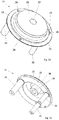
- the emergency button can have an at least partially transparent cover means.
- the covering means can be moved from an initial position into an actuating position.
- the covering means can cover the actuating element so that the actuating element is actuated via the covering means.
- the covering means serves to build up a conceptual barrier for actuation of the release element and thus to counteract improper actuation.
- the conceptual barrier arises from the fact that the user thinks that he must destroy or remove the covering means before the user can actuate the release element.
- the covering means is arranged in such a way that it cannot be removed. Because the covering means is arranged in such a way that it cannot be removed, the covering means cannot be removed. As a result, the emergency button remains as originally designed and built.
- the covering means is designed to be transparent in such a way that the actuating element can be perceived by the user through the covering means.
- the actuating element is preferably actuated indirectly via the covering means.
- “Non-removable” means in particular that the covering means cannot be removed or opened for generating the cancellation signal either.
- the non-removable arrangement in the triggering element is made possible in particular by the fact that the operator does not have to turn the actuating element in order to achieve the cancellation condition.
- the non-removable arrangement can be made possible.
- the non-removable arrangement of the cover means can be designed in various ways.
- the covering means can be mounted in such a way that it cannot be removed.
- the covering means can be guided in particular movably in the emergency button.
- the covering means can be formed from an elastic material.
- the covering means can comprise an elastic film which is stretched over the actuating element.
- the covering means can contribute to the watertight design of the emergency button.
- the covering means can be firmly connected to the actuating element.
- the connection is designed in particular in a form-fitting or material fit. This can prevent misuse, in particular the actuating element can only be moved together with the cover element.
- the security system according to the invention is particularly suitable for use in a building in which people with an impaired mental state live, in particular in a psychiatry, a dementia ward or the like.
- a psychiatry a psychiatry
- a dementia ward or the like.
- monitoring and, if necessary, activation can thereby increase the safety of the occupants.
- the object of the invention is also achieved by a method for unlocking at least one door lock, in particular for securing escape routes, according to claim 15.
- a user can be any person who uses the security system 1.
- a user can e.g. B. be a guest who wants to escape through the door secured by the security system 1.
- An operator is used to operate the security system 1.
- the operator can z. B. authenticate to the security system.
- the operator can e.g. B. Be a member of security guards.
- the operator can particularly preferably set the safety system 1.
- actuation of the emergency button is understood to mean “actuation of the actuating element of the emergency button”.
- connection to a bus system is understood to mean a direct connection, so that a component connected to the bus system is to be regarded as a participant in the bus system with its own bus address.
- Initiating activation is understood in particular to be the sending of a message via a first and / or second bus system that contains information and / or a command that causes the direct or indirect recipient of the message to perform the activation.
- the sender of the message initiates the control.
- initiating a triggering is understood to mean an indirect triggering.
- the message can in particular correspond to a bus telegram.
- an actuation means that an actuation is the cause, regardless of whether the actuation continues or not.
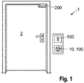
- a first embodiment of a security system 1 according to the invention for a door 2 is shown.
- Door 2 is not part of the Safety system 1 according to the invention 1.
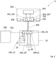
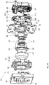
- the safety system 1 according to the invention comprises a door lock 200 and an emergency button 10.
- the emergency button 10 comprises a control device 100.
- a key switch 500 is assigned to the emergency button 10.
- the security system 1 can include the key switch 500.
- the security system 1, in particular the emergency button 10 can have a key switch input via which a connection to the key switch 500 can be established.
- the emergency button 10 and the door lock 200 are connected to one another via a first bus system 400.
- the key switch 500 is electrically connected or can be connected to the emergency button 10 via a connection 402.
- the connection 402 is shown as a dashed arrow in order to show that signals are fed to an electronics unit 24 of the emergency button 10 via a position of a key inserted into the key switch 500.
- the key switch 500 can also be connected to the first bus system 400 (not shown). This alternative applies to all exemplary embodiments.
- the emergency button 10 is designed to send a message to the door lock 200 via the first bus system 400 as a result of an actuation of the emergency button 10 and thereby to cause the door lock to be unlocked.
- the message as a result of the actuation of the emergency button 10 can be delayed.
- the safety system 1 in particular the emergency button 10, can likewise be connectable to a fire alarm (not shown). If a fire alarm signal is present, the security system 1 likewise causes the door lock 200 to be unlocked.
- the control device 100 performs functions that are not relevant to security: The control device 100 can thus cause the door lock 200 to be unlocked for authorized persons.
- the control device 100 can be connected to an access control system (not shown).
- the access control system can in particular be connected or connectable to the first bus system 400.
- the control device 100 receives from the access control system, in particular via the bus system 400, a positive authentication signal about the authentication that has taken place. Thereafter, the control device 100 causes the door lock 200 to be unlocked.
- a reader, a key switch, a keyboard for entering a code or a lock cylinder of a mechanical lock, in particular a self-locking panic lock comprise or be designed in such a way.
- control device 100 can automatically initiate unlocking of the door lock 200 at a predetermined time or after a predetermined period of time, e.g. B. if the door should be unlocked in a time window per day.
- the control device 100 can automatically initiate a re-locking after a predetermined period of time has elapsed.
- the control device 100 can also receive an access signal from the access control system and / or measure the length of the positive authentication signal.
- the control device 100 can adapt the length of the predetermined period of time by means of the access signal or on the basis of the length of the authentication signal. So a person can e.g. B. hold an ID card long in front of the reader or turn the key for a long time. This signals that the predetermined time span should correspond to a long time span previously stored in the control device 100. If the person briefly holds the ID card in front of the reader or if the user briefly turns the key, it is signaled that the predetermined period of time should correspond to a short period of time previously stored in the control device 100.
- a first door state monitoring device 204 and a second door state monitoring device 206 detect whether the door 2 is open or closed.
- the control device 100 receives at least indirectly a signal from the door status monitoring devices 204, 206. If the door lock 200 has been unlocked on the basis of a positive authentication signal, the control device 100 can initiate a re-locking of the door lock 200 immediately and automatically as soon as the control device 100 with the help of the door status monitoring devices 204, 206 the information is available that the door is initially open and now closed again.
- the emergency button 10 comprises an acoustic alarm transmitter 23 and lighting means 41 (see also Figure 13 ).
- the lighting means 41 are used to display the locked or unlocked state of the door lock 200 and thus serve as a display device.
- the lighting means 41 are used for the visual representation of a time-delayed unlocking of the door lock 200 as a result of an actuation of the emergency button 10 and thus serve as a display device.
- the lighting means 41 are used for the visual representation of an alarm state after receipt of the fire alarm signal or as a result of an actuation of the emergency button 10 and thus serve as a display.
- the lighting means 41 are used for visual representation when a previously described relocking fails.
- the control device 100 controls the acoustic alarm transmitter 23 in order to output an acoustic alarm when there is a danger, ie when a Fire alarm signal received or emergency button 10 was pressed.
- the control device 100 controls the acoustic alarm transmitter 23 in order to output an acoustic alarm if a relocking fails.
- the control device 100 controls the lighting means 41 in order to display the locked or unlocked state of the door lock 200, to visually display a time-delayed unlocking and / or to output an optical alarm when a fire alarm signal is received or the emergency button 10 has been actuated or when a relocking fails.
- the control device 100 can monitor the opening of the door with the aid of the door state monitoring devices 204, 206. If desired, the control device 100 can emit an acoustic alarm if the door 2 has been opened while the door lock 200 is in the unlocked state, at least if there is no positive authentication signal. It can be monitored when someone opens the door, even if the door is unlocked.
- the emergency button 10 can include at least one additional output.
- the control device 100 can control additional components that can be connected to the security system 1 according to the invention via the output, e.g. B. a room lamp.
- the parameters for executing the aforementioned functions of the control device 100 are stored in the control device 100. So are z. B. the predetermined time (s), the predetermined period (s), parameters for the acoustic alarms, e.g. B. at what volume and at what frequency an acoustic alarm is to be output, and parameters for the various controls of the lighting means 41 for the visual representation of the various above-mentioned states of the security system 1 are stored in the control device 100.
- the parameters for the lighting means can include flashing frequencies, colors to be emitted, color intensities and / or light patterns.
- the control device 100 can communicate with a mobile communication device via a radio module 64.
- the parameters can be set with the aid of a monitoring device 301 via a second bus system 401 (see Sect. Figures 9 and 10 ).
- a parameterization program is provided for the parameterization, which is run on a communication device, e.g. B. a personal computer, a mobile phone and / or a tablet can be executed. The operator can set the parameters using the parameterization program.
- the emergency button 10 has a first emergency button processing unit 20, a second emergency button processing unit 21 and a third emergency button processing unit 22.
- the first, second and third emergency button processing units 20, 21, 22 are each designed as microprocessors or microcontrollers.
- the first and second emergency button processing units 20, 21 comprise a non-volatile memory.
- the third emergency button processing unit 22 comprises a non-volatile memory and / or has access to a non-volatile memory.
- the first, second and third emergency button processing units 20, 21, 22 are collectively referred to as the electronic unit 24 of the emergency button 10.
- the electronic unit 24 also serves as a control device 100.
- the first emergency button processing unit 20 serves as the first processing unit 103 of the control device 100.
- the second emergency button processing unit 21 serves as a second processing unit 104 of the control device 100.
- the third emergency button processing unit 22 serves as a third processing unit 105 of the control device 100.
- the first and the second emergency button processing unit 20, 21 are used to carry out the safety-relevant functions of the emergency button.
- the third emergency button processing unit 22 or processing unit 105 is used to carry out the non-safety-related functions.
- One of the safety-relevant functions is the initiation of unlocking in the event of danger.
- the functions that are not relevant to safety include the other functions listed above.
- an actuation element 11 When the emergency button 10 is actuated, an actuation element 11 is moved from an initial position 11.I to an actuation position 11.II, whereby a switch 63 is actuated (see also FIG.
- a first and a second actuation signal are generated.
- a signal about the opening of the first circuit is detected by the first emergency button processing unit 20.
- a signal about the opening of the second circuit is detected by the second emergency button processing unit 21.
- the actuation signal is understood to be the signal that is generated by the user by actuating the actuation element in order to unlock the door lock and to get the escape route released.
- the first emergency button processing unit 20 and the second emergency button processing unit 21 each cause the door lock 200 to be unlocked independently of one another after the actuation signal has been detected via the first bus system 400.
- the second The emergency button processing unit 21 thus acts redundantly to the first emergency button processing unit 20.
- the door lock 200 includes a door lock controller 201.
- the door lock controller 201 includes a first processing means 202 and a second processing means 203.
- the first and the second processing means 202, 203 are collectively referred to as an electronic device 207.
- the first and the second processing means 202, 203 are each designed as a microprocessor or microcontroller.
- the first and the second processing means 202, 203 can each control a locking mechanism 205 of the door lock 200 for unlocking.
- d. H As a result of the actuation of the emergency button 10 or after receipt of a fire alarm signal, both the first processing means 202 and the second processing means 203 control the locking mechanism 205 for unlocking.
- the second processing means 203 is thus redundant to the first processing means 202. This structure achieves one-fault security.
- the locking mechanism 205 is designed electromechanically.
- the locking mechanism 205 comprises e.g. B. an electromechanically actuated latch element (not shown), which blocks a door latch of the door 2 in the locked state of the door lock 200 and releases the door lock 200 in the unlocked state.
- the first and the second processing means 202, 203 switch on an electrical current for the locking mechanism 205.
- the first and second processing means 202, 203 switch off an electrical current for the locking mechanism 205.
- a separate switch is assigned to each processing means 202, 203 for this purpose. Opening only one of the switches will cut off the power to the locking mechanism 205.
- the door lock controller 201 receives feedback on the status of the locking mechanism 205 via a locking mechanism status monitoring device (not shown). In particular, a position of an armature of a coil of the locking mechanism 205 is monitored. If the state of the door lock 205 does not correspond to the target state, an alarm is output. Additionally or alternatively, a new attempt can be made in this case to reach the target state.
- the first and second emergency button processing units 20, 21 communicate with the first and second processing means 202, 203 via the first bus system 400 with the aid of a message.
- the message can be the Notification of being actuated or a control command for unlocking included.
- the first emergency button processing unit 20 informs the first processing means 202 and the second emergency button processing unit 21 informs the second processing means 203 control to unlock, i.e. switch off the electrical current.
- the presence of a fire alarm signal is detected by the first and the second emergency button processing unit 20, 21.
- the first and second emergency button processing units 20, 21 thereupon cause, by means of a message to the first and second processing means 202, 203, that the locking mechanism 205 is activated for unlocking by the door locking control 201.
- the first emergency button processing unit 20 informs the first processing means 202
- the second emergency button processing unit 21 informs the second processing means 203 control to unlock, i.e. switch off the electrical current.
- the actuation of the emergency button 10 or the presence of a fire alarm signal can be sent in a message from one of the two emergency button processing units 20, 21, the first emergency button processing unit 20 writing a first part of the message and the second emergency button processing unit 21 writing a second part of the message.
- the first and the second processing means 202, 203 are each responsible for at least part of the message.
- the emergency button processing units 20, 21, 22 and the first and second processing means 202, 203 can each receive messages via the first bus system 400.
- the electronic unit 24 and the door lock control 201 can each be assigned a bus address.
- the first and second emergency button processing units 20, 21 monitor each other. If an error is detected, the electronics unit 24, in particular the intact emergency button processing unit 20, 21, causes the first and second processing means 202, 203 to trigger the door locking mechanism 205 for unlocking. The first and second processing means 202, 203 monitor each other. If an error is detected, then at least the intact processing means 202, 203 actuate the locking mechanism 205 for unlocking. Likewise, if the bus system 400 malfunctions, the locking mechanism 205 for unlocking is activated by the door locking control 201. To do this and to check the first and the second Emergency button processing unit 20, 21, a sign of life signal of the first and the second emergency button processing unit 20, 21 is regularly sent to the door lock controller 201.
- the first and second processing means 202, 203 actuate the locking mechanism 205 for unlocking.
- the first and the second processing means 202, 203 communicate with one another when the door lock control 201 has received a message about the actuation of the emergency button 10 and / or the presence of a fire alarm signal. If only the first processing means 202 or the second processing means 203 determines that the emergency button 10 has been actuated or a fire alarm signal is present, the determining processing means 202, 203 controls the door locking mechanism 205 for unlocking and initiates that the other processing means 202, 203 also initiate the Door locking mechanism 205 controls for unlocking. An error and a malfunction always include a failure of the respective component. In the event of a power failure, the locking mechanism 205 automatically changes to the unlocked state. In the processes described in this section, the security system 1 also outputs an acoustic and / or visual alarm, in particular by means of the control device 100.
- the actuation signal If the actuation signal has been generated, it is electronically prevented that the door lock 200 is transferred into the locked state without the existence of a cancellation condition. This will prevent the door from locking while a hazardous condition persists.
- an electronic detection is integrated in the electronic device 207. The electronic detection is transferred to an actuated state as a result of the actuation of the actuating element 11, which is used to release the escape route. In the actuated state, the activation of the door lock 200 for locking is prevented.
- the electronic determination comprises a first program code.
- the first program code comprises a first variable or has access to a first variable. In an initial state of the electronic detection, the first variable is set to an initial value. In the actuation state, the first variable is set to an actuation value by which the activation of the door lock 200 for locking is prevented.
- the first variable can be binary. If the cancellation condition is reached, the electronic detection is returned to an initial state. To do this, the value of the first variable is set to the initial value. In the initial state of the electronic detection, control of the door lock 200 for locking is permitted.
- the first program code detects the first value of the first variable and allows the door lock 200 to be locked if the value of the first variable corresponds to the initial value, and prevents locking of the door lock 200 when the value of the first variable corresponds to the actuation value.
- the electronic determination is stored both in the first processing means 202 and redundantly in the second processing means 203.
- the first program code is stored in the first processing means 202.
- the first variable is stored in the non-volatile memory of the first processing means 202.
- a second program code with the same functionality as the first program code is stored in the second processing means 203.
- the first variable is stored redundantly in the non-volatile memory of the second processing means 203.
- the first variable is also stored in the first emergency button processing unit 20 and in the second emergency button processing unit 21 in the non-volatile memories.
- the first variable in the first and second emergency button processing units 20, 21 is transferred from the initial value to the actuation value.
- the changed value of the first variable is transmitted to electronic device 207 via bus system 400.
- the emergency button 10 repeatedly sends the actuation value of the first variable to the electronic device 207.
- the transmission can take place at regular time intervals, in particular together with the sign of life signal.
- the actuating element 11 is designed to be non-latching. When actuated, the actuating element 11 is transferred from the starting position 11.I to the actuating position 11.II (see Fig. Figure 11 ). Immediately after actuation, the actuation element 11 moves back into the starting position 11.I by the force of a return means 12 designed as a spring (see FIG. Figure 12 , 13th ). The actuation element 11 is actuated in a translatory manner.
- the cancellation action on the emergency button 10 is carried out by actuating the actuating element 11. This generates an override signal that corresponds to the actuation signal.
- a further signal must be generated at the same time in order to achieve the cancellation condition.
- an operator authenticates himself. The authentication takes place by inserting and turning a key in the key switch 500. The actuation of the actuating element 11 and the authentication must overlap in time. I. E. the The operator must hold the key in the turned state while the actuating element 11 is in the actuating position 11.II. The actuating element 11 must return to the starting position 11.I while the key is in the turned state. The course of action is sufficient to achieve the cancellation condition.
- the cancellation condition can be achieved in at least one other way, namely by the elapse of a predetermined time interval. So z. B. after 60 seconds after the last generation of the actuation signal, the cancellation condition can be reached, provided that the door 2 has remained closed. An authentication on the key switch 500 and a cancellation action on the emergency button 10 are not necessary in this case.
- the first and the second door state monitoring devices 204, 206 are provided in order to detect with a one-fault security that the door 2 has remained closed continuously as a result of the actuation of the emergency button 10.
- the door state monitoring devices 204, 206 are preferably designed differently.
- the first door state monitoring device 204 may e.g. B. be designed as a door contact.
- the second door condition monitoring device 206 may e.g. B. be designed as a trap contact.
- z. B. at least one of the door status monitors magnetically, z. B. as a reed switch to monitor the state of door 2.
- the door lock controller 201 receives a signal from the first and the second door state monitoring device 204, 206 as to whether the door 2 is open or closed. Only if a signal about the opening of the door has not been sent by either the first door status monitoring device 204 or the second door status monitoring device 206 during the predetermined time interval, the cancellation condition can be achieved by the elapse of the predetermined time interval.
- the door lock controller 201 includes a timer to measure the predetermined time interval.
- the door lock control 201 starts the timer as a result of the actuation of the emergency button 10. If the door lock control 201 receives a signal from the first or the second door status monitoring device 204, 206 during the predetermined time interval that the door has been opened, an override must be performed on the emergency button 10. In this case, the lapse of the predetermined time interval is not enough.
- the length of the predetermined time interval is stored in the door lock controller 201.
- the door lock controller 201 checks whether reaching the release condition by the lapse of the predetermined time interval is permissible before the Door lock control 201 controls the locking mechanism 205 for locking. For example, when the security system 1 is started up, ie before the operation of the security system 1 begins, an operator can specify whether the predetermined time interval is permitted as a cancellation condition without opening the door 2 and thus leads to a re-locking of the door 2. The deposit can be made in the emergency button 10. A check of the admissibility, the lapse of the predetermined time interval and the absence of a signal from the first and the second door state monitoring device 204, 206 that the door 2 has been opened is sufficient to achieve the cancellation condition.
- the door lock control 201 communicates the open or closed state of the door via the bus 400 to the emergency button 10 and / or to the control device 100.
- the electronics unit 24 includes a timer. A first delay period can be stored in the electronics unit 24. If the door lock 200 is to be unlocked with a time delay, the electronics unit 24 waits for the first delay period after the actuation signal has been generated before the first and second emergency button processing units 20, 21 communicate with the door lock controller 201 via the first bus system 400 in order to initiate unlocking .
- the third processing unit 105 causes the to Figure 1 and 2 described non-safety-related unlocks and locks of the door lock 200, z. B. unlocking after receiving the authentication signal, at a predetermined time or after a predetermined period of time or locking after a predetermined period of time or immediately after closing the door 2.
- the third processing unit 105 communicates via the first bus system 400 with the door lock control 201.
- the communication can e.g. B. contain information or a control command which causes the door locking control 201 to control the locking mechanism for unlocking or locking.
- the control device 100 is connected to the second bus system (see Sect. Fig. 7 ), the third processing unit 105 serves to forward messages from and / or to a central escape route control 300.
- the third emergency button processing unit 22 controls the acoustic alarm transmitter 23 and the lighting means 41.
- the processing means 202, 203 sends a corresponding signal via the bus 400 to the
- the electronic device 207 is connected or can be connected to the door state monitoring devices 204, 206 and receives signals from the door state monitoring devices 204, 206 about an open or closed state of the door.
- control device 100 the door lock control 2021 and / or the emergency button 10 carry out
- Program codes are stored in the electronic device 207 and / or the electronic unit 24, with the aid of which the functions can be carried out.
- Figure 3 represents a variant of the Figures 1 and 2 safety system 1 shown.
- the control device 100 is formed separately from the emergency button 10 and the door lock 200.
- the control device 100 may e.g. B. be arranged in a DIN rail housing (not shown).
- the control device 100 is not integrated in an emergency button 10 or in a door lock 200.
- the control device 100 can be provided for arrangement in a technical room.
- the first bus system 400 connects the control device 100, the door lock 200 and the emergency button 10 to one another.
- the key switch 500 is electrically connected or can be connected to the emergency button 10 via a connection 402.
- the structure and function correspond to the first exemplary embodiment, with the functions associated with the Figures 1 and 2 are described with the aid of the control device 100 or the processing units 103, 104, 105, by the control device 100 of FIG Figure 3 are executed and the functions related to the Figures 1 and 2 are described with the help of the emergency button 10 or the emergency button processing units 20, 21, 22, are executed by the emergency button 10:
- the first and the second emergency button processing unit 20, 21 detect the actuation signal, communicate as a result of an actuation of the emergency button 10 with the first and the second processing means 202, 203 via the first bus system 400 and thus initiate activation of the locking mechanism 205 by the door lock control 201.
- the measures to achieve one-fault security or redundancy are carried out with the aid of the first and second emergency button processing units 20, 21.
- the first variable is stored in the first and the second emergency button processing unit 20, 21 and is transmitted from there to the door lock controller 201.
- the emergency button 10 includes the timer for determining the first delay period.
- the control device 100 is connected or can be connected to the second bus system 401.
- the third processing unit 105 causes the to Figure 1 and 2 described non-safety-related unlocks and locks of the door lock 200, z. B. an unlocking after receiving the Authentication signal, at a predetermined time or after a predetermined period of time or an automatic relocking after a predetermined period of time or immediately after the door 2 has been closed.
- the first, second and third processing units 103, 104, 105 are each designed as a microprocessor or microcontroller.
- the first, second and third processing units 103, 104, 105 together form processing electronics 101.
- the first and second processing units 103, 104 have a non-volatile memory.
- the third processing unit 105 comprises a non-volatile memory and / or has access to a non-volatile memory.
- a fire alarm signal can be received both by the control device 100 and by the emergency button 10.
- the presence of a fire alarm signal is detected by the first and the second emergency button processing unit 20, 21 for the emergency button 10 or by the first and the second processing unit 103, 104 for the control device 100.
- both the control device 100 with the aid of the first and second processing units 103, 104 and the emergency button 10 with the aid of the first and second emergency button processing units 20, 21 can cause the door lock 200 to be unlocked.
- communication takes place via the first bus system 400 with the door lock controller 201.
- the control device 100 is informed via the first bus system 400 when the emergency button 10 causes the door lock 200 to be unlocked, that is, as a result of the emergency button 10 being actuated or after receiving a fire alarm signal.
- the control device 100 is also informed about a time-delayed unlocking of the door lock 200 as a result of the actuation of the emergency button 10.
- the control device 100 is informed of the locking and unlocking status of the door lock 200.
- the control device 100 is informed of the open or closed state of the door 2.
- the control device 100 triggers a control of the alarm device 23 and the lighting means 41 for the Figures 1 and 2 acoustic alarms and visual displays described.
- the control device 100 can communicate with the electronics unit 24, in particular with the third emergency button processing unit 22, via the first bus system 400.
- the third emergency button processing unit 22 then controls the alarm transmitter 23 or the lighting means 41.
- the parameters for the alarm transmitter 23 and the lighting means 41 are stored in the control device 100.
- the door lock 200 comprises the door state monitoring devices 204, 206.
- the door status monitoring devices 204, 206 can be connected to the first bus system 400 or directly to the emergency button 10 and / or the control device 100.
- At least one further emergency button can be connected to the first bus system 400, which is designed without the control device 100.
- the other emergency button is like the emergency button 10 in Figure 3 formed and can cause the unlocking of the door lock 200 when actuated.
- the further emergency button corresponds in structure and functionality to the emergency button 10 of the Figure 3 .
- At least one further door lock can be connected to the first bus system 400.
- the further door lock is like the door lock 200 in Figure 2 or 3 formed and can also be unlocked when the emergency button 10 is actuated.
- the further door lock corresponds to the structure and functionality of the door locks 200 from FIG Figures 1 to 3 .
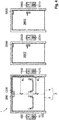
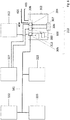
- FIG 4 a third embodiment of a security system 1 according to the invention with several emergency buttons 10, 1010, 2010, 3010 is shown.
- the security system 1 comprises several door locks 200, 1200, 2200, 3200.
- Each emergency button 10, 1010, 2010, 3010 is assigned a key switch 500, 1500, 2500, 3500.
- the security system 1 is used to arrange the emergency buttons 10, 1010, 2010, 3010 and door locks 200, 1200, 2200, 3200 on different doors 2, 2002, 3002.
- the doors 2, 2002, 3002 are not part of the security system 1 according to the invention
- Emergency buttons 10, 1010, 2010, 3010 are connected to the first bus system 400 and thus correspond to a number of emergency buttons 10, 1010, 2010, 3010.
- the door locks 200, 1200, 2200, 3200 are connected to the first bus system 400 and thus correspond to one Number of door locks 200, 1200, 2200, 3200.
- the emergency buttons 10, 1010 are assigned to the door locks 200, 1200.
- the emergency button 2010 is assigned to the door lock 2200.
- the emergency button 3010 is assigned to the door lock 3200.
- the two door locks 200, 1200 are unlocked, but not the door locks 2200, 3200.
- the emergency button 2010 is actuated, only the door lock 2200 is unlocked.
- the emergency button 3010 is actuated, only the door lock 3200 is unlocked.
- the door locks 200, 1200, 2200, 3200 are selectively unlocked.
- the emergency buttons 10, 1010 can be provided for arrangement on a double-leaf door 2.
- a door lock 200, 1200 is in each case on a door leaf 3, 4 the door 2 to be arranged.
- the emergency button 2010 and the door lock 2200 are intended to be arranged on a further door 2002.
- the emergency button 3020 and the door lock 3200 are to be arranged on a door 3002, as in Figure 4 shown.
- the security system 1 off Figure 4 can also be used by Figure 4 different selective unlockings can be set.
- one of the emergency buttons 10, 1010, 2010, 3010 is actuated, only a single assigned door lock 200, 1200, 2200, 3200 is unlocked.
- only one door lock 200, 1200, 2200, 3200 is assigned to each emergency button 10, 1010, 2010, 3010.
- a security system 1 set in this way is suitable for four single-leaf doors, each with a door lock 200, 1200, 2200, 3200.
- the security system 1 when one of the emergency buttons 10, 1010 is actuated, only the two door locks 200, 1200 and when one of the emergency buttons 2010, 3010 is actuated, only the two other door locks 2200, 3200 are unlocked.
- the emergency buttons 10, 1010 are thus assigned to the door locks 200, 1200 and the emergency buttons 2010, 3010 are assigned to the door locks 2200, 3200.
- the security system 1 set in this way is suitable for two double-leaf doors, each with a door lock 200, 1200, 2200, 3200 per door leaf.
- the safety system 1 can also be set in such a way that all door locks 200, 1200, 2200, 3200 are unlocked when an emergency button 10, 1010, 2010, 3010 is actuated.
- a security system 1 can include a number of emergency buttons 10, 1010, 2010, 3010, which does not coincide with the number of door locks 200, 1200, 2200, 3200.
- the door 2 can be single-leaf and one of the emergency buttons 10, 1010 or one of the door locks 200, 1200 is missing.
- the emergency buttons 10, 1010, 2010, 3010 and the door locks 200, 1200, 2200, 3200 are connected to one another via the first bus system 400.
- an emergency button 10, 1010, 2010, 3010 is electrically connected or can be connected to a key switch 500, 1500, 2500, 3500 assigned to the respective emergency button 10, 1010, 2010, 3010 via a connection 402, 1402, 2402 or 3402.
- the key switches 500, 1500, 2500, 3500 are connected to the first bus system 400 (not shown).
- the control device 100 is in one of the emergency buttons 10, 1010, 2010, 3010, z. B. the emergency button 10, integrated.
- the first bus system 400 is only connected to a single control device 100.
- the structure and the functions of the door locks 200, 1200, 2200, 3200 correspond to the structure and the functions of the door lock 200 of the Figures 2 and 3
- the structure and functions of the emergency button 10 the structure and functions of the emergency button 10 of the Figure 2
- the structure and functions of the emergency button 1010, 2010, 3010 the structure and functions of the emergency button 10 of the Figure 3 .
- the reference numbers from the Figures 2 and 3 are used. It goes without saying that the door locks 200, 1200, 2200, 3200 each have their own door locking mechanism, their own processing means, etc. and the emergency buttons 10, 1010, 2010, 3010 each include their own emergency button processing units, alarm transmitters, lamps, switches and actuating elements.
- an assignment of the emergency buttons 10, 1010, 2010, 3010 to the door locks 200, 1200, 2200, 3200 is made when the safety system 1 is started up, i.e. before the start of operation of the safety system 1 , 2010, 3010 for the door locks 200, 1200, 2200, 3200.
- one of the door locks 200, 1200, 2200, 3200 is transferred to an assignment mode.
- a conscious action is then carried out on the emergency buttons 10, 1010, 2010, 3010.
- the conscious action can be implemented as an actuation of the actuating element 11 of the respective emergency button 10, 1010, 2010, 3010.
- the assignment mode of the door lock 200, 1200, 2200, 3200 is ended.
- the door lock 200 is transferred to the assignment mode and then the emergency button 10, 1010 is actuated, whereby the assignment of the emergency button 10, 1010 to the door lock 200 takes place.
- the assignment mode of the door lock 200 is ended.
- the door lock 1200 is transferred to the assignment mode and then the emergency button 10, 1010 is actuated, whereby the assignment of the emergency button 10, 1010 to the door lock 1200 takes place.
- the assignment mode of the door lock 1200 is ended.
- the door lock 2200 is now transferred to the assignment mode and then the emergency button 2010 is actuated, whereby the assignment of the emergency button 2010 to the door lock 2200 takes place.
- the assignment mode of the door lock 2200 is ended.
- the door lock 3200 and the emergency button 3010 can then be used accordingly.
- the assignment stores in the respective door locks 200, 1200, 2200, 3200, in particular in the respective door lock controls 201, which emergency button 10, 1010, 2010, 3010 is to be assigned to the respective door lock 200, 1200, 2200, 3200.
- the assignment of the emergency buttons 10, 1010, 2010, 3010 to the door locks 200, 1200, 2200, 3200 is stored.
- a bus address, in particular an unchangeable bus address, of the respective emergency buttons 10, 1010, 2010, 3010 is stored for the assignment.
- the assignment is stored in the respective door locks 200, 1200, 2200, 3200 in each case in the first digital processing means 202 and redundantly in the second digital processing means 203, in particular in the non-volatile memories of the processing means 202, 203.
- the emergency button 10 communicates with all door locks 200, 1200, 2200, 3200 of the first bus system 400.
- the door locks 200, 1200, 2200, 3200 each check, based on the deposit, whether the respective door lock 200, 1200, 2200, 3200 has been assigned to the actuated emergency button 10.
- the assigned door locks 200, 1200 then control the respective door lock mechanism 205 only in the case of assignment.
- the door locks 200, 1200, 2200, 3200 which are assigned to the emergency button 10, 1010, 2010, 3010 receiving the fire alarm signal, are unlocked.
- a first delay time is stored in that emergency button 10, 1010, 2010, 3010.
- the storage takes place during the commissioning of the safety system 1 by the parameterization program.
- the operator can store a different first delay time for each emergency button 10, 1010, 2010, 3010. For example, a first delay period is stored in the emergency button 10, which differs from the first delay period that is stored in the emergency button 2010.
- the emergency buttons 1010, 3010 should cause the assigned door locks 2200 or 3200 to be unlocked without a time delay, so that no first delay period or a first delay period of 0 s is stored in the emergency buttons 1010, 3010.
- the security system 1 can be designed in such a way that the same first delay time is always stored in the emergency buttons 10, 1010, 2010, 3010, which are assigned to the same door lock 200, 1200, 2200, 3200.
- the parameterization program allows the operator only one common setting.
- the control device 100 takes over the non-safety-related functions for unlocking and locking all door locks 200, 1200, 2200, 3200, as before Figure 1 and 2 described. To this end, the control device 100 can use the Door locks 200, 1200, 2200, 3200 communicate selectively. In the control device 100 it is stored which door lock 200, 1200, 2200, 3200 is assigned to which access control system, so that only the assigned door lock (s) 200, 1200, 2200, 3200 are unlocked in the event of a positive authentication signal from an access control system. It is also stored in the control device 100 whether and when, which door lock 200, 1200, 2200, 3200 is to be unlocked at what predetermined time.
- the deposits can be made differently for each door lock 200, 1200, 2200, 3200 or for the groups of door locks 200, 1200, 2200, 3200 that are to be arranged on a door 2, 2002, 3002.
- the storage is made with the help of the parameterization program by the operator during commissioning.
- the control device 100 causes an acoustic and visual alarm to be output as a result of the actuation of an emergency button 10, 1010, 2010, 3010 in the at least one further emergency button 10, 1010, 2010, 3010, which is the same door lock 200, 1200, 2200, 3200 how the activated emergency button 10, 1010, 2010, 3010 is assigned. If in the embodiment of the Figures 4 and 5 z. If, for example, the emergency button 10 is actuated, the control device 100, through communication with the electronics unit 24 of the emergency button 1010, also causes the acoustic alarm transmitter 23 and the lighting means 41 of the emergency button 1010 to output an acoustic or optical alarm.
- the control device 100 causes the first delay period with which the unlocking is initiated also in the at least one further emergency button 10, 1010, 2010, 3010 is shown, which is assigned to the same door lock 200, 1200, 2200, 3200 as the actuated emergency button 10, 1010, 2010, 3010.
- the control device 100 communicates with the electronics unit 24 of the at least one further emergency button 1010, 2010, 3010 or controls the lighting means 41 of the emergency button 10, in which the control device 100 is integrated.
- the control device 100 can change the non-safety-related assignment to selective communication, e.g. B. assign an access control system to a door lock 200, 1200, 2200, 3200 based on a bus address.
- the participants of the first bus system 400 each have a setting device for manually setting a bus address.
- the setting device can comprise DIP switches. At least the participants in the first bus system 400 who have the same setting on the setting device are automatically assigned to one another. In order to be able to assign different bus addresses to subscribers with the same setting, subscribers of the first bus system 400 have different identification numbers, from which different bus addresses are configured with the aid of the setting made.
- the bus address that is determined with the help of the setting is for the emergency buttons 10, 1010, 2010, 3010 and for the door locks 200, 1200, 2200, 3200, just another bus address that the emergency buttons 10, 1010, 2010, 3010 and Use the door locks 200, 1200, 2200, 3200 in addition to the bus address that is used for safety-related communication.
- the control device 100 can prevent a further door lock 200, 1200, 2200, 3200 from being unlocked until a condition exists, provided there is no danger. If the condition is met, the control device 100 causes the further door lock 200, 1200, 2200, 3200 to be unlocked. In this way, the control device 100 communicates with several door locks 200, 1200, 2200, 3200 in such a way that a lock is formed.
- the door 2002 can be arranged at an entrance to a room and the door 3002 can be arranged at an exit of the same room.
- the control device 100 can initiate an unlocking of the door lock 2200 when there is a positive authentication signal for the door lock 2200.
- the control device 100 can prevent the unlocking of the door lock 3200 until a condition is met. If the condition is present, the control device 100 causes the door lock 3200 to be unlocked. B. a lock time interval or the achievement of a measured variable such as room temperature, humidity, air purity or the number of people in the room.
- the control device 100 can be or can be connected to a measuring device.
- the condition may include closing the first opened door 2002, which is measurable by the door condition monitoring devices 204, 206.
- the condition and the door locks 2200, 3200 involved in the lock can be stored in the control device 100. The operator can store the data using the parameterization program.
- FIG. 6 is a variant of the Figures 4 and 5 illustrated security system 1 shown.
- the control device 100 is designed separately from the emergency buttons 10, 1010, 2010, 3010 and the door locks 200, 1200, 2200, 3200.
- the first bus system 400 connects the control device 100 with the door locks 200, 1200, 2200, 3200 and the emergency buttons 10, 1010, 2010, 3010.
- the control device 100 of FIG Figure 6 corresponds to the structure of the control device 100 Figure 3 .
- the emergency button 10 of the Figure 6 corresponds in structure to the emergency button 10 of the Figure 3 . Otherwise, the structure and the functionalities correspond to those previously Figure 5 are described, the structure and the functionalities of the security system 1 of Figure 6 .
- the bus system 400 can comprise at least two cables for communication and at least two cables for power supply.
- the bus system 400 has exactly two cables for communication and two cables for power supply.
- a power supply unit can be integrated as a connection to a power supply system at any point in the bus system 400.
- the power supply unit can thus be provided as an independent component of the safety system 1 outside the emergency button 10 or the emergency button 10, 1010, 2010, 3010 and the door lock 200 or the door locks 200, 1200, 2200, 3200.
- the security system 1 is flexible in terms of its spatial structure.
- the electronic detection only prevents the emergency buttons 10, 1010, 2010, 3010 assigned door locks 200, 1200, 2200, 3200 can be locked. Reaching the cancellation condition enables the locking of the door lock (s) 200, 1200, 2200, 3200 assigned to the actuated emergency button 10, 1010, 2010, 3010. 1010, 2010, 3010, which was previously actuated, and the authentication on the key switch 500, 1500, 2500, 3500 assigned to the actuated emergency button 10, 1010, 2010, 3010 is necessary.
- At least this course of action is necessary for the door lock 200, 1200, 2200, 3200 assigned to the actuated emergency button 10, 1010, 2010, 3010, in which at least one of the Door state monitoring devices 204, 206 has detected that the door 2 or one of the door leaves 3, 4 was opened after the emergency button 10 was actuated.
- the cancellation condition can be achieved by the lapse of the predetermined time interval. So the cancellation condition can e.g. B. be reached after 60 seconds after the last actuation of the emergency button 10.
- the admissibility of whether locking should take place after the predetermined time interval has elapsed with door 2, 2002, 3002 remaining closed, can be for each door lock 200, 1200, 2200, 3200 or for groups of door locks 200, 1200, 2200, 3200, in particular for door locks which are intended to be arranged on the same door can be individually set and stored.
- the deposit can e.g. B. in the emergency buttons 10, 1010, 2010, 3010.
- the length of the predetermined time interval can be stored in an individually adjustable manner.
- a minimum length, e.g. B. 60 s be fixed for the predetermined time interval.
- the storage is done by the parameterization program.
- FIG. 7 a fifth embodiment of the security system 1 according to the invention is shown.
- the fifth embodiment comprises the security system 1 according to the first embodiment of FIG Figures 1 and 2 . That is to say, the emergency button 10, which comprises the control device 100, is connected to the door lock 200 via the bus system 400.
- the key switch 500 is connected or can be connected to the emergency button 10 via a connection 402.
- further components 300, 301, 510 are provided compared to the first exemplary embodiment.
- the security system 1 comprises the central escape route control 300.
- the central escape route control 300 is provided to be arranged remotely from the door 2. So the central escape route control 300 z. B. together with a guard device 301, which can be designed as a monitor or personal computer, and / or a multi-door display device 350 (see Sect. Fig. 10 ) to be arranged in a guard room.
- the guard device 301 is optionally part of the security system 1 according to the invention. Alternatively, the guard device 301 can be connected to the security system 1 according to the invention.
- the central escape route control 300 has a modular structure.
- An emergency module 310 comprises a first mounting plate 311.
- the first mounting plate 311 takes a central one Emergency button 302 and an identification device 312 embodied by way of example as a key switch.
- the central emergency button 302 and the identification device 312 are mechanically rigidly connected to one another by means of the first fastening plate 311.
- the central emergency button 302 is used to unlock the door lock 200 when the central emergency button 302 is actuated.
- the door lock 200 can thus be unlocked by the central emergency button 302 remote from the door 2.
- the unlocking as a result of the actuation of the central emergency button 302 takes place with a one-fault security.
- the actuation of the central emergency button 302 is therefore suitable for the case of danger.
- a deactivation module 320 comprises a first operating element 322 designed as a key switch and a second operating element 323 designed as a button.
- the first operating element 322 is used to deactivate the emergency button 10 Transferred state. If the emergency button 10 is in a deactivated state, the door lock 200 is not unlocked when the emergency button 10 is actuated.
- the second operating element 323 is used to activate the emergency button 10. If the emergency button 10 is in the deactivated state and becomes the second operating element 323 is actuated, the emergency button 10 is transferred to an activated state. In the activated state of the emergency button 10, the emergency button 10 causes the door lock 200 to be unlocked when the emergency button 10 has been actuated.
- the deactivation module comprises a second fastening plate 321.
- the second fastening plate 321 serves to accommodate the first and second operating elements 322, 323.
- the second fastening plate 321 connects the first and second operating elements 322, 323 with one another in a mechanically rigid manner.
- a delay module 330 comprises a third fastening plate 331.
- the third fastening plate 331 receives a delay element 332.
- the delay element 332 is designed, for example, as a key switch.
- the delay element 332 serves to further delay the unlocking of the door lock 200 within the first delay period.
- the delay module 330 comprises a termination element 333, which is designed as a button.
- the termination member 333 is attached to the third attachment plate 331.
- the termination element 333 is mechanically rigidly connected to the delay element 332 by means of the third fastening plate 331. By actuating the termination element 333, the delay in unlocking the door lock 200 can be ended.
- the central escape route control 300 comprises an escape route control housing 340 which is open on one side and in which the emergency module 310, the deactivation module 320 and the delay module 330 are arranged.
- the deactivation module 320 and the delay module 330 are optional components of the central escape route safety device 300.
- the multi-door display device 350 if present, can also be arranged in the escape route control housing 340.
- the escape route control housing 340 can mechanically secure the emergency module 310, the deactivation module 320 and the delay module 330.
- the emergency module 310, the deactivation module 320 and the delay module 330 are each individually fastened, in particular screwed, to the escape route control housing 340.
- the first fastening plate 311 for the emergency module 310, the second fastening plate 321 for the deactivation module 320 and / or the third fastening plate 331 for the delay module 330 are used for fastening to the escape route control housing 340.
- the escape route control housing 340 and the modules 310, 320, 330 are designed so that different orders in which the modules 310, 320, 330 can be arranged next to one another, are possible. So z. B.
- the emergency module 310 can be arranged between the deactivation module 320 and the delay module 330.
- a free space can be arranged on the left, delay module 330 in the middle and the emergency module 310 on the right. The free space is created by the lack of the deactivation module 320 and is covered by a plate.
- the escape route control housing 340 can have rails for inserting the modules 310, 320, 330.
- the escape route control housing 340 may have mounting options, e.g. B. perforated strips or elongated holes for the variable attachment of the module 310, 320, 330 have.
- a purely schematically illustrated display area 314, 324 and 334 is provided on the first fastening plate 311, on the second fastening plate 321 and on the third fastening plate 331.
- a purely schematically illustrated display area 314, 324 and 334 is provided on the first fastening plate 311, on the second fastening plate 321 and on the third fastening plate 331.
- optical lights for displaying states of the security system 1 can be provided in the display areas 314, 324, 334.
- the security system 1 further comprises an audio and video module 510.
- the audio and video module 510 is provided for arrangement in the vicinity of the door 2, which can be locked by the door lock 200. If the audio and video module 510 is enabled, an operator in the guard room can speak to the user in front of door 2 and see the room near door 2.
- the central emergency button 302 is constructed similarly to the emergency button 10.
- the central emergency button 302 thus comprises an emergency button electronics unit 308.
- the emergency button electronics unit 308 comprises a first emergency processing unit 303, a second emergency processing unit 304 and a third emergency processing unit 305.
- the first, second and third emergency processing units 303, 304, 305 are each designed as a microprocessor or microcontroller.
- the first and second emergency processing units 303, 304 have a non-volatile memory.
- the third emergency processing unit 305 has a non-volatile memory and / or has access to a non-volatile memory.
- the central emergency button 302 is actuated by actuating an emergency button actuator 306. This actuates an emergency button switch 307.
- a first and a second circuit (not shown) are opened.
- a signal of the opening of the first circuit is detected by the first emergency processing unit 303.
- a signal about the opening of the second electric circuit is detected by the second emergency processing unit 304.
- the central emergency button 302 is connected to a second bus system 401.
- the control device 100 is also connected to the second bus system 401.
- the second bus system 401 is a different type of bus system than the first bus system 400.
- the second bus system 401 can be designed as a LON or LAN bus and the first bus system 400 as a CAN or DCW bus.
- the emergency button 10 comprises the control device 100.
- the emergency button 10 and the door lock 200 shown in FIG Figure 9 are shown correspond to the emergency button 10 and the door lock 200 of the Figure 2 .
- control device 100, the emergency button 10 and the door lock 200 educated.
- the control device 100, the emergency button 10 and the door lock 200 are connected to one another via the first bus system 400, the control device 100 being connected to the second bus system 401.
- the control device 100 receives messages from the central escape route safety device 300 via the second bus system 401.
- the control device 100 forwards the messages to other participants in the first bus system 400 via the first bus system.
- the message can in particular contain information regarding an actuation of the central emergency button 302, the key switch 312, the first operating element 322, the second operating element 323, the delay element 332 and / or the termination element 333 or a control command as a result of an actuation of one of the aforementioned elements 302 , 312, 322, 323, 332, 333.
- the control device 100 is integrated in the emergency button 10, there is no need to forward it to the emergency button 10 in which the control device 100 is integrated.
- the control device 100 forwards the message to the door lock 200.
- Control device 100 and emergency button 10 are connected via first bus system 400, control device 100 forwards the message to emergency button 10 and / or door lock 200.
- the control device 100 adapts the message to the format of the first bus system 400. Otherwise security-related messages are left untouched.
- the central emergency button 302 If the central emergency button 302 has been actuated, the first emergency processing unit 303 and redundantly the second emergency processing unit 304 cause the door lock 200 to be unlocked.
- the central emergency button 302 communicates via the control device 100 with the door lock controller 201, in particular the first and second processing means 202, 203.
- the first and the second processing means 202, 203 then control the locking mechanism 205.
- the first and second processing units 103, 104 have previously forwarded the message.
- the control device 100 has left the content of the message untouched.
- the central emergency button 302 has an input for receiving a fire alarm signal. If the fire alarm signal is received, the central emergency button 302 causes the door lock 200 to be unlocked.
- the first and second emergency processing units 303, 304 communicate via the control device 100, namely via the first and second processing units 103, 104, with the door lock control 201, Like previously described.
- a signal about an actuation of the key switch 312 of the first module 310 is received by the emergency button electronics unit 308, in particular the third emergency processing unit 305.
- the emergency button electronics unit 308 sends a message regarding the actuation of the key button 312 via the second bus system 401 to the control device 100.
- the control device 100 forwards the message to the first bus system 400.
- the emergency button actuating element 306 is designed to be non-latching.
- the emergency button actuating element 306 is identical to the actuating element 11 of the emergency button 10 (see Fig. Figures 13 to 15 ).
- the emergency actuation element 306 is thus transferred from an initial position to an actuation position when it is actuated (analogous to Figure 11 ).
- the emergency actuation element 306 moves back into the starting position by the force of a resetting means designed as a spring (analogous to Figure 11 ).
- the emergency actuation element 306 is actuated in a translatory manner.
- the electronic device 207 prevents, by means of the electronic detection, that without the presence a cancellation condition, the door lock 200 can be brought back into the locked state.
- the cancellation condition after actuation of the central emergency button 302 can be achieved by actuation of the key button 312. In particular, actuation of the key switch 312 is sufficient to achieve the cancellation condition.
- the cancellation condition can be reached in another way as a result of actuation of the emergency button 10: If the door status monitoring devices 204, 206 have detected that the door 2 remained closed after the emergency button 10 was actuated is, the release condition can be achieved by the elapse of a predetermined time interval and a release treatment at the central escape route controller 300 after the predetermined time interval.
- the cancellation treatment can correspond to an authentication at the central escape route control 300, in particular to an actuation of the key switch 312. By the Aufhe treatment, z. B. actuation of the key switch 312, a cancel signal can be generated.
- the cancellation signal is forwarded to the door lock controller 201 via the control device 100. An authentication on the key switch 500 and a cancellation action on the emergency button 10 are not necessary in this case.
- the door lock control 201 checks whether reaching the cancellation condition by the elapse of the predetermined time interval and the authentication at the central escape route control 300 with the door 2 remaining closed is permissible before the door lock control 201 controls the locking mechanism 205 to lock. For example, when the security system 1 is started up, an operator can specify whether the predetermined time interval may elapse without opening the door 2 and the additional actuation of the key switch 312 is permissible as a cancellation condition and thus leads to a re-locking of the door 2.
- This variant can, for. B. can be selected by the operator if only the lapse of the predetermined time interval with the door 2 remained closed does not appear safe enough to the operator. The operator can select and save this variant using the parameterization program.
- the elapse of the predetermined time interval with the door 2 remaining closed is optically displayed on the central escape route control 300.
- the lighting means 313 serve to indicate that the predetermined time interval has elapsed without a signal regarding the opening of the door 2 being received within the predetermined time interval. The operator learns from the visual display that the authentication on the central escape route control 300 enables the door 2 to be locked.
- the door lock 200 can also be locked by the same actuation of the key switch 312 after the fire alarm signal has ended.
- the possibility of locking the door lock 200 by actuating the key switch 312 after the fire alarm signal has ended is also indicated optically by the lighting means 313.
- the control device 100 forwards messages from the emergency button 10 and / or the door lock 200 via the second bus system 401. In this case, the control device 100 adapts the message to the format of the second bus system 401. The control device 100 sends information about the state of the emergency button 10 and / or the door lock 200 via the second bus system 401.
- the central escape route control 300 and the multi-door display device 350 can be connected to a third bus system 403 (see FIG. Fig. 10 ).
- the central emergency button 302, particularly preferably the emergency button electronics unit 308, can preferably be connected to the third bus system 403 (see FIG. Fig. 8 ).
- the multi-door display device 350 can visually display the locked and unlocked state of the door lock 200.
- one of the door locks 200, 200 ', 1200', 2200 'of the security system 1 can be unlocked.
- the unlocking with the aid of the multi-door display device 350 is not single-fault-safe.
- the third bus system 403 can be the same type of bus system as the first bus system 400, e.g. B. a CAN or DCW bus.
- the control device 100 forwards the central escape route control 300 via the second bus system 401 when the emergency button 10 waits a first delay period before the emergency button 10 causes the door lock controller 201 to activate the locking mechanism 205 for unlocking.
- the first delay period is visually displayed on the central escape route control 300.
- the central emergency button 302 is corresponding to the emergency button 10 built like it to the Figures 13 , 16, 17 is described.
- the lighting means 313 of the central emergency button 302 are activated by the emergency button electronics unit 308 for the visual representation of the first delay period.
- fewer illuminants 313 light up in the same color.
- fewer illuminants 313 can shine in a first color and an increasing number of illuminants 313 can illuminate in a second color.
- the lighting means 41 of the emergency button 10 are activated in an identical manner in order to visually represent the first delay period.
- the operator can actuate the delay element 332.
- the operator turns a key in the key switch, which serves as a delay element 332.
- An actuation of the delay element 332 is detected by the emergency button electronics unit 308, in particular the third emergency processing unit 305.
- a corresponding message is sent via the second bus system 401 and possibly the first bus system 400.
- the emergency button 10 receives the message.
- the emergency button 10 ends the first delay period and begins with a second delay period.
- the second delay period e.g. B. 180 s, is longer than the first delay period.
- the emergency button 10 causes the door lock 200 to be unlocked.
- the second delay period is determined in the emergency button 10 with the aid of the same timer that is used to determine the first delay period.
- the key of the delay element 322 does not have to remain turned. Rather, turning the key once is sufficient to start the second delay period.
- the second delay period is visually displayed on the central escape route control 300 and on the emergency button 10.
- the visual representation on the central escape route control 300 is the same as the visual representation on the emergency button 10.
- fewer illuminants 41, 313 light up in the same color.
- fewer illuminants 41, 313 can shine in a first color and an increasing number of illuminants 41, 313 can illuminate in a second color.
- a pattern associating time e.g. B. a circumferential color point or a circumferential color window (see description for Figure 16, 17 ) are represented optically.
- the emergency electronics unit 308 detects the actuation of the termination element 333 and sends a message regarding the actuation of the termination element 333 via the second bus system 401.
- the emergency electronics unit 308 causes the emergency button 10 not to delay unlocking any further, but rather to immediately initiate an unlocking of the door lock 200.
- the termination element 333 is designed to be non-latching. A single actuation of the termination element 333 is sufficient to end the delay in causing the unlocking.
- the emergency button 10 can be switched to the deactivated state by actuating the first operating element 322. To do this, the operator turns a key in the key switch, which serves as the first operating element 322. An actuation of the first operating element 322 is detected by the emergency button electronics unit 308. When the first operating element 322 is actuated, a first and a second deactivation circuit are opened or closed. The opening or closing of the first deactivation circuit is detected by the first emergency processing unit 303. The opening or closing of the second deactivation circuit is detected by the second emergency processing unit 304.
- the first and second emergency processing units 303, 304 communicate with the emergency button 10 via the second bus system 401. If the first bus system 400 is located between the emergency button 10 and the central emergency button 302, the control device 100 forwards the message to the first and second emergency processing unit 303 , 304 continue. When forwarding, the format is changed, but the content remains unchanged.
- the activated state and the deactivated state are electronically stored in the emergency button 10. Because the activated state and the deactivated state are stored in the emergency button 10, the key in the first operating element 322 does not have to remain turned during the deactivated state. Rather, a single turn of the key is sufficient to deactivate the emergency button 10.
- the deactivation remains until the second operating element 323 is actuated.
- the actuation of the second operating element 323 can be detected by the emergency button electronics unit 308, in particular the third emergency processing unit 305.
- the emergency electronics unit 308 sends a message regarding the actuation of the second operating element 323 via the second bus system 401 and possibly via the first bus system 400 to the emergency button 10, whereupon the emergency button 10 is switched to the activated state.
- the second operating element 323 is not latching. Because the activated and deactivated states are stored in the emergency button 10, a single actuation is sufficient of the second operating element 323 in order to transfer the emergency button 10 into the activated state.
- the central escape route control 300 comprises a bus 341, via which the emergency electronics unit 308, in particular the third emergency processing unit 305, can detect signals from the second operating element 323, the delay element 332 and the termination element 333.
- the emergency electronics unit 308 serves as the intelligence of the entire central escape route control 300 .. Only the emergency electronics unit 308 comprises microprocessors.
- the deactivation module 320 and / or the delay module 322 can be configured in a processor-free manner.
- the bus 341 can be configured as an I 2 C bus.
- a second variable can be stored in the first emergency button processing unit 20 and redundantly in the second emergency button processing unit 21, in particular in the non-volatile memories.
- the second variable can be binary. If the emergency button 10 is in the deactivated state, the second variable is set to a deactivation value. If the emergency button 10 is in the activated state, the second variable is set to an activation value. As a result of actuation of the first operating element 322, the second variable is set to the deactivation value. As a result of actuation of the second operating element 323, the second variable is set to the activation value. Before the emergency button 10 causes the door lock 200 to be unlocked, the emergency button 10 checks the value of the second variable. If the emergency button determines that the emergency button 10 is deactivated, there is no communication between the emergency button 10 and the door locking control 201 in order to initiate an unlocking 200.
- the first emergency processing unit 303 and the second emergency processing unit 304 monitor each other for errors. If an error is found, a message is sent via the second bus system 401.
- the emergency button 10 receives the message and then transfers itself to the activated state if the emergency button 10 is in the deactivated state. For this purpose, the emergency button 10 changes the value of the second variable to the activation value.
- the first emergency processing unit 303 and the second emergency processing unit 304 send repeatedly, in particular at regular intervals, a sign of life signal via the second bus system 401.
- the emergency button 10 receives the sign of life signals. If there is no sign of life one or more times, the emergency button 10 is switched to the activated state if the emergency button 10 is in the deactivated state.
- the emergency button 10 changes to the activated state if the emergency button 10 is in the deactivated state.
- the actuation of the emergency button 10 in the deactivated state is displayed on the central escape route control 300, on the monitoring device 301 and / or on the multi-door display device 350. If there is actually a case of danger, the operator can switch the emergency button 10 to the activated state by actuating the second operating element 323, or the operator can directly control the door lock for unlocking. To do this, the operator can press the central emergency button 302. The operator can e.g. B. perceive via the audio and video module 510. This increases security.
- the deactivation can e.g. B. be made at night in a department store. It is also conceivable to use the deactivatable emergency button 10 in a building in which people with an impaired mental state live. Emergency buttons 10 can also be used on doors to which people with impaired mental state have access, e.g. B. on a psychiatric or dementia ward.
- the actuation of the emergency button 10 carried out in the deactivated state does not lead to an unlocking of the door lock 200 even after the transfer to the activated state In the deactivated state, actuation of the emergency button 10 remains ineffective. This is due, on the one hand, to the fact that the actuating element 11 and the switch 63 are designed to be non-latching. On the other hand, the actuation of the emergency button 10 in the deactivated state was not stored in the emergency button 10. The door lock control 201 does not receive any message regarding the actuation of the emergency button 10 in the deactivated state. The electronic detection was therefore not transferred to the actuated state. This ensures that the door lock 100 is not unlocked immediately with the activation of the emergency button 10, e.g. B. because long before the emergency button 10 was pressed. This increases building security.
- the audio and video module 510 is switched on during the first and / or the second delay period.
- the emergency button 10 enables the audio and video module 510 at the beginning of the first and / or second delay period.
- the audio and video module 510 is also enabled by the emergency button 10 when the emergency button 10 is actuated in the deactivated state.
- the emergency button 10 communicates via the second Bus system 401 and possibly via the first bus system 400 with the audio and video module 510.
- the emergency button 10 can only be deactivated if the audio and video module 510 can be activated. If the audio and video module 510 is part of the security system 1 according to the invention, deactivation can be omitted if the audio and video module 510 z. B. is not functional and / or the connection to the audio and video module 510 is disturbed. This does not apply if the security system 1 does not include an audio and video module 510, but a monitoring system separate from the security system 1 is provided in the building.
- the emergency button 10 only delays the initiation of unlocking by the first and / or second delay period if the audio and video module 510 can be activated. If the audio and video module 510 is part of the security system 1 according to the invention, there is no delay if the audio and video module 510 z. B. is not functional and / or the connection to the audio and video module is disturbed. This does not apply if the security system 1 does not include an audio and video module 510, but a monitoring system separate from the security system 1 is provided in the building.
- FIG 10 a further embodiment of a security system 1 according to the invention is shown.
- the security system 1 comprises a central escape route control 300, which according to the Figures 7 and 8th is constructed. Key switches 500, 500 ', 1500, 1500', 2500 associated with the respective emergency buttons 10, 10 ', 1010, 1010', 2010 are not shown for the sake of clarity.
- the central escape route control 300 is connected to the second bus system 401.
- a first subsystem 5 and a second subsystem 6 are connected to the second bus system 401.
- the two subsystems 5, 6 each include a first bus system 400, 400 '.
- Emergency buttons 10, 1010 or 10 ', 1010', 2010 'and door locks 200 or 200', 1200 ', 2200' are connected to the respective first bus system 400, 400 '.
- the first bus systems 400, 400 ' are the same type of bus system, e.g. B. a CAN or a DCW bus.
- the second bus system 401 is a different type of bus system, e.g. B. a LON or LAN bus.
- the security system 1 comprises the multi-door display device 350.
- the multi-door display device 350 can e.g. B. visually indicate which door lock 200 or 200 ', 1200', 2200 'is in the unlocked state and which door lock is in the unlocked state. With the aid of the multi-door display device 350, an operator can lock and unlock individual door locks 200 or 200 ', 1200', 2200 'of the security system 1 that are not relevant to safety.
- Each subsystem 5, 6 comprises only one control device 100, 100 '.
- the control device 100, 100 ′ of the respective subsystem 5, 6 is connected to the second bus system 401.
- the control device 100 of the first subsystem 5 is connected to the emergency buttons 10, 1010 and the door lock 200 of the first subsystem 5 via the first bus system 400.
- the control device 100 'of the second subsystem 6, however, is integrated in an emergency button 10' of the second subsystem 6 and connected to the remaining emergency buttons 1010 ', 2010' and the door locks 200 ', 1200', 2200 'of the further first bus system 400'.
- a first emergency button 10 and a second emergency button 1010 are provided in the subsystem 5. If one of the emergency buttons 10, 1010 is actuated, the actuated emergency button 10, 1010 in each case causes the door lock 200 to be unlocked.
- a first emergency button 10 ', a second emergency button 1010' and a third emergency button 2010 ' are provided in the subsystem 6.
- first emergency button 10 ' is actuated
- second emergency button 1010 ' is actuated
- second door lock 1200' is released
- third emergency button 2010 'is actuated only the third door lock 2200' is released.
- an inventive security system 1 z. B. be designed without the first or the second subsystem 5, 6.
- a single or additional subsystem e.g. B. one of the Figures 1 to 6 described security systems 1 according to the invention be provided.
- the design and functions of the emergency buttons 10, 10 ', 1010, 1010', 2010 'and the door locks 200, 200', 1200 ', 2200' are designed according to the previous exemplary embodiments, unless described additionally or differently below.
- each of the door locks 200, 200 ', 1200', 2200 'of the security system 1 it is stored whether the respective door lock 200, 200'1200', 2200 'is unlocked when the central emergency button 302 is actuated. So z. B. the door locks 200, 200 ', 2200' allow unlocking as a result of an actuation of the central emergency button 302, but the door lock 1200 'does not. If the central emergency button 302 is actuated, the door lock controls 201 of the door locks 200, 200 ', 2200' control the respective locking mechanism 205 for unlocking. In contrast, there is no such activation in the door lock 1200 '.
- the storage of whether the door lock 200, 200'1200 ', 2200' is unlocked as a result of an actuation of the central emergency button 302 is made when the safety system 1 is started up by the operator.
- the storage is done by the parameterization program.
- each of the emergency buttons 10, 1010, 10 '. 1010 ', 2010' is stored as to whether, when the first operating element 322 is actuated, a transfer to the deactivated state for the respective emergency button 10, 1010, 10 '. 1010 ', 2010' or not. This results in a selective deactivation by actuating the only first control element 322 of the security system 1.
- the emergency buttons 10, 10 ', 2010' are switched to the deactivated state as a result of an actuation of the first operating element 322, but the emergency buttons 1010, 1010 'are not.
- the control devices 100, 100 'receive a corresponding message via the second bus system 401 and forward the message to all emergency buttons 10, 1010, 1010', 2010 'of the respective first bus system 400, 400' that are not the control device 100 comprise, further.
- the emergency buttons 10, 1010, 10 '. 1010 ', 2010' of the security system 1 decide on the basis of the deposit on the authorization for deactivation whether the respective emergency button 10, 1010, 10 ', 1010', 2010 'switches itself to the deactivated state as a result of the actuation of the first operating element 322 or not.
- the third variable can be implemented in binary.
- the third variable is stored in the non-volatile memory of the respective first and second emergency button processing units 20, 21 of each emergency button 10, 1010, 10 ', 1010', 2010 '. If the deactivation is permitted for the respective emergency button 10, 1010, 10 ', 1010', 2010 ', the third variable assumes a first value. If the deactivation for the respective emergency button 10, 1010, 10 ', 1010', 2010 'is prohibited, the third variable assumes a second value.
- the storage of whether the emergency button 10, 1010, 10 ', 1010', 2010 'should be able to be deactivated is made when the safety system 1 is started up by the operator. This is stored with the help of a parameterization program.
- each of the emergency buttons 10, 1010, 10 '. 1010 ', 2010' is stored as to whether the respective emergency button 10, 1010, 10 'is activated when the delay element 332 is actuated. 1010 ', 2010' the unlocking of the emergency button 10, 1010, 10 '. 1010 ', 2010' associated door locks 200, 200 ', 1200', 2200 'delayed by a second delay period or not.
- the second delay time is for the respective emergency buttons 10, 1010, 10 '. 1010 ', 2010' adjustable for different lengths and stored in the security system 1, in particular in the emergency buttons 10, 1010, 10 ', 1010', 2010 '.
- the delay by the second delay time period and possibly the length of the second delay time period can only be allowed for groups of emergency buttons 10, 1010, 10 '. 1010 ', 2010', which are assigned to a door lock 200, 200 ', 1200', 2200 'or a door 2, 2002, 3002, can be individually adjusted.
- the setting and the storage are carried out by the operator with the aid of the parameterization program.
- the emergency buttons 10, 2010 ' further delay the unlocking of the door locks 200 or 2200' as a result of an actuation of the delay element 332, but the emergency buttons 1010, 10 ', 1010' do not.
- the length of the second delay period for the emergency button 10 is selected to be different from the length of the second delay period for the emergency button 2010 '. If the emergency button 10 is actuated and the delay element 332 is actuated within the first delay period that is stored for the emergency button 10, the emergency button 10 delays the unlocking by the second delay period that is stored in the emergency button 10 from the actuation of the delay element 332 .
- the emergency button 2010 If the emergency button 2010 'is actuated and if the delay element 332 is actuated within the first delay period that is stored for the emergency button 2010', the emergency button 2010 'delays the unlocking by the second delay time that is in the emergency button from the actuation of the delay element 332 2010 'is stored and which differs from the second delay time for the emergency button 10. If the emergency button 1010 is actuated, the emergency button 1010 delays the unlocking by the first delay time that is stored for the emergency button 1010.
- the delay element 332 is actuated during the first delay period of the emergency button 1010, the unlocking is not delayed by a second delay period, since this delay is not permitted for the emergency button 1010, but the emergency button 1010 is activated after the first delay period immediately cause the door lock 200 to be unlocked.
- the emergency buttons 10 ', 1010' do not delay the unlocking of the associated door lock 200 'or 1200' at all. In the case of the emergency buttons 10 ', 1010', neither a first delay period nor a second delay period is permitted. Instead of not allowing a delay by the first and / or the second delay period, a period of 0 s can also be stored. Actuation of the termination element 333 terminates any delay in unlocking.
- the control devices 100, 100 'receive a corresponding message via the second bus system 401 and forward the message to the emergency buttons 10, 1010, 1010', 2010 'of the respective first bus system 400, 400' that are not the Control device 100 include, further.
- the emergency buttons 10, 1010, 10 '. 1010 ', 2010' of the security system 1 decide on the basis of the deposit how to proceed.
- the storage of whether the emergency button 10, 1010, 10 ', 1010', 2010 'allows the delay by the second delay period and, if so, the storage of the length of the second delay period, takes place when the security system 1 is put into operation Determined by the operator using the parameterization program.
- the first and / or the second delay period can only be selected up to a maximum, fixedly predetermined period of time.
- the operator can also selectively store which cancellation condition is permitted for which emergency button 10, 1010, 1010 ', 2010'.
- the cancellation condition for the cancellation act on site is always permitted.
- the reaching of the cancellation condition by the elapse of the predetermined time interval or the reaching of the cancellation condition by the elapse of the predetermined time interval and subsequent actuation of the identification device 312 with the door 2 remaining closed can or not be selectively permitted.
- the storage of whether the emergency button 10 can be deactivated when the first operating element 322 is actuated, whether the emergency button 10 is to delay unlocking by a second delay period when the delay element 332 is actuated, the length of the first and the second delay period, the storage of the cancellation condition and / or the storage of whether the door lock 200 is to be unlocked when the central emergency button 302 is actuated can also be used for the security system 1 according to the exemplary embodiment of FIG Figures 7 to 9 be made.
- a plurality of central escape route controls 300, 300 ′ can also be connected to the second bus system 401.
- a central escape route control 300 can be provided in a psychiatry for arrangement in a guard room and a further central escape route control 300 'can be provided for arrangement in a nurses' room.
- the parameterization program can be used to store which of the central emergency buttons 302, 302' are to be unlocked as a result of an actuation.
- a list is stored in the door locks for this purpose.
- the parameterization program can be used to store which of the first operating elements 322, 322' can be deactivated as a result of an actuation.
- a list is stored in each of the emergency buttons 10, 10 ', 1010, 1010', 2010 '.
- the first to fourth exemplary embodiments of the security system 1 according to the invention have no second bus system 401, no central escape route control 300, no security device 301 and no audio and video module 510.
- exemplary embodiments of the security system 1 according to the invention are conceivable in which the first to fourth exemplary embodiments additionally at least partially include the missing components 401, 301, 300 and 510. If the security system 1 is designed for several doors, an audio and video module 510 can be assigned to each door.
- the emergency buttons 1010, 2010, 3010, which do not include the control device 100, and the door locks 200, 1200, 2200, 3200 are not connected to the second bus system 401.
- the door locks 200, 200 ', 1200, 1200', 2200, 2200 ', 3200 are part of the security system 1 according to the invention.
- the door locking controls 201 can each be connected to the locking mechanism 205 and, if necessary, to the door status monitoring devices 204, 206.
- the door lock 200 is not unlocked in the security system 1, but part of the security system 1 is that the door lock control 201 controls the locking mechanism 205, ie the door lock control 201 switches the electrical current for the locking mechanism 205 on or off.
- the terms “unlocking or locking the door lock” “control of the locking mechanism for unlocking or locking” can be used.
- an emergency button 10 is shown.
- the in Figure 11 The emergency button 10 shown is as an emergency button 10, 10 ', 1010, 1010', 2010, 3010 in one of the safety systems 1 according to the invention Figures 1 to 10 can be used or used.
- the emergency button 10 comprises the actuating element 11.
- the actuating element 11 can move from the starting position 11.I, which is in the Figure 11 is shown, move into the actuation position 11.11, which is shown in Figure 11 is indicated. In Figure 12 the actuating element 11 is also in the starting position 11.I.
- the switch 63 In the actuation position 11.II the switch 63 is actuated.
- the switch 63 here also changes from a first 63.I to a second position 63.11, as in FIG Figure 12 indicated.
- the actuation element 11 After actuation, the actuation element 11 returns immediately and without manual intervention to the starting position 11.I.
- a resetting means 12 designed as a spring is provided in the emergency button 10. The switch 63 also returns to the first position 63.I immediately after actuation and without manual intervention.
- the emergency button 10 comprises at least a first circuit board 60. This makes it possible to design the emergency button 10 in a compact manner and with a secure mode of operation.
- the emergency button 10 has a height AH of less than 48 mm, preferably less than 45 mm, particularly preferably less than 43 mm, from a dome 32 of a front surface 19 of the actuating element 11 in the installation direction.
- the switch 63 is attached to the first circuit board 60.
- the first and second circuits are interrupted on the first circuit board 60 by actuation of the switch 63.
- the emergency button 10 also includes a second circuit board 61.
- the first, second and third emergency button processing units 20, 21, 22 are arranged on the second circuit board 61.
- the arrangement of the first, second and third emergency button processing units 20, 21, 22 is independent of whether the first, second and third emergency button processing units 20, 21, 22 serve as processing units 103, 104, 105 of control device 100.
- the opening of the first and second electrical circuits can be detected wirelessly by the first and the second emergency button processing unit 20, 21, respectively.
- the first and the second circuit board 60, 61 are connected to one another via plugs 68.
- the first and second sinkers 60, 61 are arranged at a fixed distance from one another.
- bolts 69 are provided which fasten the first and second plates 60, 61 to one another at a fixed distance from one another by means of screws 70 (see Fig. Figure 13 ).
- the first and second sinkers 60, 61 are arranged in parallel to each other.
- the emergency button 10 comprises a mounting plate 62.
- the mounting plate 62 is also arranged at a fixed distance from the first and second circuit boards 60, 61.
- bolts 71 are provided which connect the mounting plate 62 to the first board 61 via screws 72.
- the mounting plate 62 is used for attachment to a flush-mounted box.
- the flush-mounted box can have a diameter of 60 mm and a depth of 41 mm.
- the part of the emergency button 10 extending from the mounting plate 62 in the installation direction is referred to as the installation part 73.
- the built-in part 73 has a diameter of less than 60 mm and a depth of less than 33 mm, preferably less than 31 mm, particularly preferably less than 29 mm. This means there is enough space for cables in the flush-mounted box.
- the distance MP from an underside of the mounting plate 62 to an upper side of the second circuit board 62 is less than 22 mm, preferably less than 20 mm, particularly preferably less than 17 mm.
- the mounting plate 62 can also be used for fastening to a cover element of a surface-mounted housing (not shown).
- the specified distances apply in particular to an emergency button in which the Bluetooth module 64 is fastened, in a departure from the illustration in the figures, on an underside of the second circuit board 61.
- the canceling action that is performed directly on the emergency button 10 is performed without rotating the operating element 11 and the switch 63.
- the switch 63 is designed in such a way that the switch 63 does not rotate.
- the switch 63 has a height SH of less than 20 mm, preferably less than 17 mm, particularly preferably less than 15 mm.
- the actuating element 11 has rod-shaped guide means 35.
- the guide means 35 are guided in guide sleeves 65.
- the guide sleeves 65 are connected to the mounting plate 62. In order to achieve good guidance, one of the guide sleeves 65 extends through the first plate 60.
- the guide means 35 are arranged parallel to the switch 63.
- the guide means 35 prevent a rotary movement of the actuating element 11 about an imaginary axis 701 which runs in the actuating direction 700.
- the actuating element 11 can only be moved in a translatory manner.
- the actuation element 11 has an actuation means 36.
- the actuating means 36 is designed in the form of a circular cylinder. This ensures that the actuating means 36 always actuates the switch 63.
- a first and a second switching element 74, 75 of the switch are always actuated at the same time (see Sect. Figure 13 ).
- the first circuit is opened by the first switching element 74 and the second circuit is opened by the second switching element 75.
- the actuation means 36 is designed with a hollow interior 38.
- a light source (not shown) is arranged in the switch 63. The light emitted by the light source is guided through the hollow interior 38 to the dome 32 of the front surface 19 of the actuating element 11, where the light passes through the actuating element 11.
- the dome 32 thus serves as an illuminating area 32 of the actuating element 11.
- the actuating element 11 can comprise an opaque base body 33.
- the base body 33 can be provided with an opening.
- a light-permeable, in particular translucent insert (not shown) can be arranged in the opening. The insert can be fastened, in particular pressed in, in the opening. As a result, the actuating element 11 can be manufactured in a particularly simple manner.
- the front surface 19 is partially conical.
- the illuminating area 32 forms the tip of the truncated cone.
- the illumination area 32 protrudes from a cover 14 of the emergency button 10 against the actuation direction 700. As a result, the light that leaves the illumination area 32 is clearly visible to the side of the emergency button 10.
- the restoring means 12 has a cavity 37.
- the actuation means 36 of the actuation element 11 and the switch 36 with the first and the second switching element 74, 75 protrude. This results in a space-saving arrangement.
- the Bluetooth module 64 is arranged between the first and second circuit boards 60, 61.
- the Bluetooth module 64 is used for parameterization.
- the Bluetooth module 64 is attached to a side of the second circuit board 61 facing away from the actuating element 11. As a result, the distance between the first and the second circuit board 60, 61 can be further reduced.
- a sabotage switch 66 is arranged on the first circuit board 60. Due to the low structural height, an actuation extension 67 of the sabotage switch 66 is passed through the mounting plate 62. The actuation extension 67 rests directly on the cover 14 of the emergency button 10.
- the emergency button 10 can include the functions described above and thus be designed in an intelligent manner despite the low structural height AH.
- the functions described above are carried out with the aid of a program code that is stored in at least one of the processing units 103, 104, 105.
- the emergency button 10 has a cover means 13.
- the covering means 13 is transparent and covers the front surface 19 of the actuating element 11. In this way, the covering means 13 prevents the actuating element 11 from being directly touched by a user.
- the covering means 13 serves as a mental obstacle for the user.
- the covering means 13 remains non-destructive when the emergency button 10 is actuated.
- the covering means 13 moves from an initial position 13.I into an actuating position 13.11.
- the actuating element 11 is actuated by the user only indirectly via the covering means 13.
- the covering means 13 is arranged in such a way that it cannot be removed from the emergency button 10. This ensures that a user cannot improperly remove the covering means 13.
- the covering means 13 is firmly connected to the actuating element 11.
- the covering means 13 has extensions 27 which are shown in FIG Figure 13 are shown.
- the actuating element 11 has holes 28 through which the extensions 27 are guided and connected to the actuating element 11 in a materially bonded manner.
- the actuating element 11 has a flange-like section 31 to which the covering means 13 is attached.
- the flange-like section 31 has the holes 28.
- the flange-like section 31 serves as a stop for the actuation element 11 in the actuation direction 700.
- the actuation element 11 reaches the actuation position 11 .II when the flange-like section 31 rests on the mounting plate 62 or on the guide sleeves 65.
- the flange-like section 31 serves as a stop of the actuating element 11 against the actuating direction 700.
- the actuating element 11 reaches the starting position 11. I when the flange-like section 31 is in contact with a light guide 40.
- the light guide 40 holds the actuating element 11 against the force of the restoring means 12.
- the light guide 40 has a contact surface 51.
- the light guide 40 is attached to the mounting plate 62. As a result, the actuating element 11 remains held against the force of the restoring means 12 even when the cover 14 is removed.
- the light guide 40 has a flange 52 with which the light guide 40 is attached to the mounting plate 62 (see FIG. Fig. 17 ).
- the light guide 40 is through the same screws 72 are attached to the mounting plate 62 by which the mounting plate 62 is attached to the first board 60.
- the covering means 13 can be designed as an elastic film which spans the actuating element 11.
- the distance between the actuating position 11.II and the starting position 11.I and the distance between the actuating position 13.11 and the starting position 13.I correspond to one another.
- the covering means 13 is moved back into the starting position 13.I.
- the restoring means 12 is used for this purpose.
- the restoring means 12 transfers the covering means 13 indirectly via the actuating element 11 into the starting position 13.I.
- the covering means 13 and the actuating element 11 each have a circular cross section.
- the cover 14 has a circular recess 15.
- the covering means 13 protrudes through the recess 15 counter to the actuation direction 700.
- the actuating element 11 likewise protrudes through the recess 15.
- the recess 15, the actuating element 11 and the covering means 13 have a common imaginary axis 701.
- the recess 15, the actuating element 11 and the covering means 13 are arranged concentrically.
- the covering means 13 has an actuating surface 17 which is spaced apart from the front surface 19 of the actuating element 11.
- the covering means 13 likewise has a side surface 16 which is designed at a distance from the side surface 18 of the actuating element 11.
- the transparent cover means 13 can protrude far from the cover 14, while the partially opaque actuating element 11 protrudes only to a small extent from the cover 14.
- the light guide 40 which is essentially flat with the cover 14, remains clearly visible even to users standing at an angle in front of the emergency button 10.
- the light guide deviates by a maximum of ⁇ 3 mm, preferably a maximum of ⁇ 2 mm, particularly preferably ⁇ 1 mm, from a flat end with the cover 14.
- the emergency button 10 can be operated by the user with the flat of his hand.
- the covering means 13 in the actuating position 13.II is flat with the cover 14 or the covering means 13 protrudes from the cover 14 in the actuating position 13.II against the actuating direction 700.
- the distance ABS between the starting position 13.I and the actuation position 13.II corresponds at most to the distance DF between an elevation 30 of the actuation surface 17 and the cover 14.
- the amount of the distance AB also corresponds to the Actuation position 11.II and the starting position 11.I at most the distance DF.
- the distance ABS and the amount of the distance AB correspond to the distance DF.
- the emergency button 10 comprises lighting means 41.
- the lighting means 41 serve to indicate the unlocked and locked state of the door lock 200.
- the lighting means 41 indicate the unlocked and locked state of the assigned door lock or door locks 200, 1200, 2200, 3200.
- the lighting means 41 are arranged concentrically around the actuating element 11. For example, the unlocked state is indicated by a green light and the locked state is indicated by a red light. In particular, all illuminants 41 emit the same light in order to indicate the locked and unlocked state, at least if there is no danger.
- the lighting means 41 can be controlled in at least two groups. Due to the different control are z. B. possible patterns by means of which further states of the security system 1 are displayed to the user. As a result of the additional display options, a large number of states can be displayed to the user and / or the operator in a compact and simple manner without additional display means. This increases the security of the security system 1.
- FIG 13 6 of the eight individual illuminants 41 present by way of example are shown as six individual illuminants, of which three illuminants are provided with the reference numerals 41a, 41b, 41c.
- the individual illuminants are referred to below as 41a, 41b, 41c, etc.
- Each of the individually controllable groups of lighting means 41 can only comprise a single lighting means 41a, 41b, 41c, etc.
- each lamp 41a, 41b, 41c, etc. can be controlled individually.
- Each lamp 41a, 41b, 41c, etc. is designed as an RGB LED.
- the lighting means 41a, 41b, 41c, etc. can be controlled in such a way that each lighting means 41a, 41b, 41c, etc. can emit at least four different, preferably at least five different colors. This can be, for. B. red, blue, yellow, green and pink light.
- the lighting means 41 are controlled by the third emergency button processing unit 22.
- the emergency button processing unit 22 and the lighting means 41 are connected to a ring bus (not shown).
- the lighting means 41 are arranged on the first circuit board 60.
- the acoustic alarm transmitter 23 is also arranged on the first circuit board 60. The acoustic alarm transmitter 23 is activated by the third emergency button processing unit 22.
- the emergency button 10 can only display the unlocked state when all of the door locks 200, 1200 assigned to the emergency button 10 are in the unlocked state.
- the unlocked state is only displayed when the entire width of the escape door of the two door leaves 3, 4 is available for escape.
- the emergency button 10 already indicates the unlocked state when one of the door locks 200, 1200 or all of the door locks of a door leaf 3, 4 are in the unlocked state.
- the possibility of escape is indicated as early as possible when one of the door leaves 3, 4 is already unlocked.
- the options can be selected by the operator.
- z. B. a switch (not shown) in the security system 1 can be provided.
- the lighting means 41 can indicate whether a fire alarm signal is present or whether an actuation signal has been generated.
- the lighting means 41 can be controlled in such a way that the progression of the time delay of the unlocking is indicated by the lighting means 41 after the actuation signal has been generated.
- a fault can be represented by the lighting means 41.
- the error that can be represented in this way can be an error in the safety system 1.
- the control device 100, the door lock control 200 or the first or the second emergency button processing unit 20, 21 of the security system 1 is not operational, defective, failed, deliberately switched off or removed.
- the error can be an error in the alarm system connected to the security system 1, which is not operational, defective, failed, deliberately switched off or removed.
- the light guide 40 comprises a plurality of light guide areas 44 (see fig Figures 16 and 17 ). Each of the lighting means 41a, 41b, 41c, etc. is assigned a light guide area 44.
- the light guide 40 can be conceptually divided into the light guide areas 44. Recesses 46 are provided between the light guide areas 44. As a result of the cutouts 46, the light remains essentially in the light guide regions 44.
- Each light guide region 44 has a forwarding section 48.
- the forwarding section 48 is arranged in the transmission direction 702 above the lighting means 41.
- the transmission direction 702 takes place opposite to the actuation direction 700.
- the forwarding section 48 serves to guide light up to a spreading one Section 45 of the light guide region 44.
- the spreading section 45 spreads open in the transmission direction 702.
- the spreading section 45 adjoins the relay section 48 in the direction of transmission 702.
- the spreading section 45 serves to widen the light beam of the emitted light.
- the forwarding section 48 widens less than the spreading section 45.
- the light guide 40 is formed in one piece.
- the light guide 40 is made of the same material, in particular monolithic.
- the light guide 40 is made of translucent material.
- the light guide areas 44 have a connecting section 49.
- the connecting section 49 adjoins the spreading section 45 in the transmission direction 702.
- the connecting sections 49 of the light guide regions 44 are integrally connected to one another in such a way that the one-piece and materially uniform light guide 40 results.
- the connecting sections can have a depth of 2 mm to 6 mm, preferably 3 mm to 5 mm, particularly preferably 3.5 mm to 4.5 mm.
- the light from one of the illuminants 41a, 41b, 41c etc. is almost limited to a luminous area 50a, 50b, 50c, 50d, 50e, 50f, 50g, 50h on the surface 47 of the light guide 40 facing the user.
- each light guide area 44 comprises a lighting area 50a, 50b, 50c, 50d, 50e, 50f, 50g, 50h.
- the surface 47 of the light guide 40 corresponds to a circular ring.
- the luminous areas 50a, 50b, 50c, 50d, 50e, 50f, 50g, 50h are designed as sectors of the circular ring. By emitting the light of a lighting means 41a, 41b, 41c, etc., the associated lighting area 50a, 50b, 50c, 50d, 50e, 50f, 50g, 50h is illuminated.
- the circular ring surrounds the actuating element 11.
- the lighting means 41 can be controlled in such a way that at least one lighting means 41a, 41b, 41c, etc. emits light of one color and at least one further lighting means 41a, 41b, 41c, etc. simultaneously emits light of a different color.
- the luminous areas 50a, 50b, 50e, 50f can display light of one color
- the luminous areas 50c, 50d, 50g and 50h can display light of a further color.
- the lighting areas 50c, 50d, 50g and 50h can be illuminated by lighting means 41, which emit flashing light.
- luminous areas 50a, 50b, 50e, 50f illuminated by light of a first color and the luminous areas 50c, 50d, 50g and 50h by light of a second color; then the luminous areas 50a, 50h, 50d, 50e are illuminated by the light of the first color and the luminous areas 50b, 50c, 50f and 50g from the light of the second color; then the luminous areas 50h, 50g, 50d, 50c are illuminated by the light of the first color and the luminous areas 50a, 50b, 50e and 50f are illuminated by the light of the second color, creating the impression of a circumferential color window.
- the opposing luminous areas 50 ie the luminous areas 50, which lie on a straight line leading through the imaginary axis 701, in FIG Figure 14 namely 50a and 50e or 50b and 50f or 50c and 50g or 50d and 50h, are preferably illuminated in the same way, ie in the same color and the same flashing frequency.
- the pattern can thus also be guessed at for users standing at an angle in front of the emergency button 10, even if at least one of the opposing luminous areas 50 is covered by the actuating element 11.
- the illuminating area 32 protrudes at most 10 mm, preferably at most 7 mm, particularly preferably at most 5 mm above the light guide 40.
- the emergency button 10 can comprise a brightness sensor (not shown).
- the brightness sensor measures the ambient brightness of the emergency button 10. If the ambient brightness decreases, the light intensity of the light emitted by the lighting means 41 is also reduced.
- parameters can be set via a mobile communication device, e.g. B. in what way the lamps are to be controlled in what state of the security system 1.
- the parameters include the flashing frequencies of the lighting means 41, whether a continuous or a flashing light is to be emitted, which state is to be indicated by which color.
- the settings are stored in an electronic memory of the security system 1, in particular of the control device 100.
- the display of certain states cannot be selected by the operator and can be permanently stored in the electronic memory. The operator can himself select states of the security system 1 that the operator would like to display through the lighting means 41.
- colors and / or patterns can be emitted by the lighting means 41 which are not assigned to any state in a predetermined manner.
- the operator can choose which state the operator would like to have indicated by the blue light.
- the parameterization via the monitoring device 301 is possible.
- the change in the state of the door lock 200 is then displayed after the door lock controller 201 sends the state change to the control device 100 has communicated.
- the control device 100 then controls the lighting means 41 or causes the lighting means 41 to be activated.
- the central emergency button 302 is constructed almost identically to the emergency button 10.
- the actuation element 11 corresponds in function and structure to the emergency button actuation element 306.
- the switch 63 corresponds to the emergency button switch 307.
- the central emergency button 302 also includes a reset means corresponding to the reset means 12.
- the central emergency button 302 comprises a first and a second circuit board and / or a mounting plate, which are constructed and connected to one another in accordance with the first circuit board 60, the second circuit board 61 or the mounting plate 62.
- the alarm transmitter 309 and the lighting means 313 corresponding to the alarm transmitter 23 and the lighting means 41 are arranged on the first circuit board of the central emergency button 302.
- the first to third emergency processing units 303, 304, 305 are arranged on the second circuit board of the central emergency button 302.
- the emergency button switch 307 ends on the first board of the central emergency button 302.
- a first and a second circuit are opened on the first board, which can be detected wirelessly by the first and the second emergency processing unit 303, 304.
- the first and the second circuit board are connected via plugs.
- the light guide of the central emergency button 302 corresponds in structure and function to the light guide 40.
- the lighting means 313 can be controlled in accordance with the lighting means 41.
- a covering means 13 corresponding to the covering means 13 is configured differently or is missing.
- the lighting means 313 are not used to visually display a locked state of an emergency button 10.
- the lighting means 313 are used to visually display the first and second delay time periods and / or to visually display that an opening treatment is possible.
- the security system 1 does not necessarily have to include all functions that are described in the description for at least one of the Figures 1 to 10 is mentioned, can perform. Rather, in the security system 1, the functions that are described in the description at least one of the Figures 1 to 10 mentioned are deposited. However, in order to be able to execute the functions, the functions must be activated. This takes place in that the control device 100 communicates with a communication module 801.
- the communication module 801 is designed as a chip card.
- the communication module 801 comprises a memory in which at least one code for enabling at least one function is stored.
- the communication module 801 comprises a microprocessor which is only used to encrypt the code.
- the communication module 801 is pushed into a receptacle 77 of the control device 100 (see FIG. Figure 18a ). As a result of the arrangement in the receptacle 77, the communication module 801 is mechanically held in the receptacle 77 in a form-fitting and / or force-fitting manner. At the same time, the arrangement in the receptacle 77 makes electrical contact with the communication module 801, so that the control device 100 can read out the at least one code from the communication module 801. The control device 100 and the communication module 801 are wired here (not shown).
- control device 100 To read out the code, the control device 100 must first be given access to the communication module 801 with the aid of a password. The control device 100 must decrypt the at least one code before the function can be activated. By activating the function, the program code that can be used to execute the function is activated.
- the program code with which the function can be executed is enabled. If the program code is stored on the emergency button 10 and the control device 100 and the emergency button 10 are connected to one another by the first bus system 400, the control device 100 initiates activation in the emergency button 10 via the first bus system 400 after reading the code of the communication module 801 If the program code is stored in the door lock control 201, the control device 100 initiates activation in the door lock control 201 via the first bus system 801 after the code of the communication module 801 has been read out.
- a code can activate a function or several functions, in particular function blocks.
- the function only remains enabled if the code is read out again from the communication module 801 repeatedly, in particular at regular time intervals. For this purpose, predetermined, non-adjustable time intervals can be stored in the control device 100. After the specified time interval has elapsed, the control device 100 blocks the function if the associated code could not be read from the communication module 801. If the function is carried out by the emergency button 10, which is connected to the control device 100 via the first bus system 400, the control device 100 causes the function to be blocked via the first bus system 400. If the function is carried out by the door lock controller 201, which is connected to the control device 100 via the first bus system 400, the control device 100 causes the function to be blocked via the first bus system 400.
- the communication module 801 is referred to below as the mother module 801.
- the further communication module 802 is referred to below as an auxiliary module.
- the auxiliary module 802 is designed as a chip card.
- the auxiliary module 802 comprises a memory in which at least one code for enabling the additional function is stored.
- the auxiliary module 802 comprises a microprocessor which is only used to encrypt the code.
- the code Code3, which is stored on the auxiliary module 802, is read out by the control device 100 (see Sect. Figure 18b ).
- the control device 100 To read out the code Code3, the control device 100 must first be given access to the auxiliary module 802 with the aid of a password. The control device 100 must decrypt the at least one code before the function can be activated.
- the code Code3 of the auxiliary module 802 is stored in a memory 107 of the control device 100 (see FIG. Figure 18c ). Then the code of the auxiliary module 802 is deleted on the auxiliary module 802 (see Figure 18c ). The auxiliary module 802 is removed from the receptacle 77. Then the mother module 801 is pushed into the receptacle 77 (see Fig. Figure 18d ). The code of the auxiliary module 802 is stored on the mother module 801 (see Sect. Figure 18d ). The code is deleted from the memory of the control device 100 (see Sect. Figure 18d ). The additional function is activated.
- the code is not stored in the control device 100 (see Sect. Fig. 18a, i ).
- the code is not deleted. Rather, the mother module 801 serves for a permanent arrangement in the receptacle 77.
- the codes Code1, Code2, Code3 stored on the mother module 801 become read out repeatedly.
- the control device 100 decides on the basis of an identifier K801, K802 of the communication module 801, 802 whether it is a mother module 801 or an auxiliary module 802.
- the identifier K801, K802 is electronically stored in particular on the mother module 801 and the auxiliary module 802.
- the identifier K801 of the mother module 801 differs from the identifier K802 of the auxiliary module 802.
- Insertion and removal from the receptacle 77 can be reserved for an operator.
- the receptacle 77 is arranged inaccessible to an unauthorized user.
- the sabotage switch 66 is actuated in the event of an unauthorized attempt to gain access to the receptacle.
- the receptacle can be between the first board 60 and the second board 61, for. B. on an underside of the first board 60, can be arranged.
- a mother module 801 In order for the security system 1 to be functional, a mother module 801 must be arranged in a receptacle 77 of the security system 1. So that the safety system 1 remains functional longer than the specified time interval, the mother module 801 must remain in the receptacle 77.
- Each emergency button 10, 10 ', 1010, 1010', 2010, 2010 ', 3010 comprises a receptacle 77.
- Exactly one mother module 801 is necessary and provided for each first bus system 400, 400' of the safety system 1. Only when the mother module 801 is inserted into the receptacle of an emergency button 10, 10 ', 1010, 1010', 2010, 2010 ', 3010, does the emergency button 10, 10', 1010, 1010 ', 2010, 2010', 3010 serve at the same time as a control device 100 for the corresponding first bus system 400, 400 '.
- the same program codes are stored as in the control device 100. Without the mother module 801, however, the program codes are not activated, so that the remaining emergency buttons 10, 10 ', 1010, 1010', 2010, 2010 ', 3010 cannot serve as control device 100. Because the mother module 801 is located in the receptacle 77, the emergency button 10, 10 ', 1010, 1010', 2010, 2010 ', 3010 serves as a control device 100.
- control device 100 is to be designed separately from the emergency buttons 10, 10 ', 1010, 1010', 2010, 2010 ', 3010 and the door locks 200, 200', 1200, 1200 ', 2200, 2200', 3200, a mother module is used 801 pushed into a receptacle 77 of the processing electronics 101. Because the mother module 801 is located in the receptacle 77, the processing electronics 101 are able to carry out the functions of the control device 100.
- the security system 1 comprises several subsystems 5, 6 and thus several first bus systems 400, 400 ', then the security system 1 includes exactly the same number of mother modules 801, 801' as there are subsystems 5, 6 (see Sect. Figure 10 ).
- the emergency button 10 ' which communicates with the mother module 801', and the processing electronics 101 of the control device 100 Figure 10 , which communicates with the mother module 801, are also provided to be connected to the second bus system 401.
- the communication module 801, 801 ', 802 can have a gap 803 through which an in particular self-adhesive tape is guided.
- the self-adhesive tape is used to manually remove the communication module 801, 801 ', 802 from the receptacle 77.
- the self-adhesive tape includes information about the functions that can be enabled by the codes stored on the respective communication module 801, 801', 802. The information can be a color code, a QR code and / or a bar code.
- the communication module 801, 801 ', 802 can be designed as a chip card with a flexible section. Part of the chip card protruding from exception 77 can be linked to the information, i. H. the color code, the QR code and / or the bar code.
- a mother module 801 that has been used once in a security system 1 can be used again in a functional manner in a receptacle 77 of another security system 1 according to the invention.
Landscapes
- Business, Economics & Management (AREA)
- Emergency Management (AREA)
- Lock And Its Accessories (AREA)
Claims (15)
- Système de sécurité (1) pour déverrouiller au moins un verrou de porte (200), en particulier le contrôle des issues de secours,dans lequel le système de sécurité (1) comprend un élément déclencheur (10), en particulier un bouton-poussoir d'urgence (10),dans lequel l'élément déclencheur (10) comprend un élément d'actionnement actionnable manuellement (11), dans lequel en actionnant l'élément d'actionnement (11) un signal d'actionnement peut être généré pour déverrouiller le verrou de porte (200),dans lequel le système de sécurité (1) comprend un dispositif électronique (207) et, du fait du signal d'actionnement, le dispositif électronique (207) empêche électroniquement qu'un mécanisme de verrouillage (205) du verrou de porte (200) puisse être actionné pour verrouiller sans la présence d'une condition d'annulation,dans lequel l'élément d'actionnement (11) est actionné de manière mécanique et sans loquet,dans lequel l'actionnement de l'élément d'actionnement (11) peut être effectué de telle manière que l'élément d'actionnement (11) est mobile d'une position de départ (11.I) à une position d'actionnement (11.II), dans lequel l'élément d'actionnement (11), suite à l'actionnement, est mobile sans intervention manuelle de la position d'actionnement (11.11) à la position de départ (11.1), dans lequel, afin de remplir la condition d'annulation, un signal d'annulation peut être généré par une action d'annulation effectuée directement sur l'élément déclencheur (10) et dans lequel le système de sécurité (1) comprend un dispositif d'authentification (500) affecté à l'élément déclencheur (10) ou est connecté en communication au dispositif d'authentification (500) affecté à l'élément déclencheur (10), dans lequel, afin de remplir la condition d'annulation, à la fois le signal d'annulation a été généré et un processus d'authentification a eu lieu sur le dispositif d'authentification (500),caractérisé en ce quele signal d'annulation peut être généré en actionnant l'élément d'actionnement (11).
- Système de sécurité (1) selon la revendication 1, caractérisé en ce que l'élément d'actionnement (11), suite à l'actionnement, est mobile sans intervention manuelle, par un moyen de rappel (12) de la position d'actionnement (11.II) à la position de départ (11.I).
- Système de sécurité (1) selon la revendication 1 ou 2, caractérisé en ce qu'un premier code de programme est stocké dans le dispositif électronique (207), dans lequel le premier code de programme, du fait que le signal d'actionnement a été généré, empêche que le mécanisme de verrouillage (205) puisse être actionné pour verrouiller sans la présence de la condition d'annulation, dans lequel en particulier un premier code de programme est stocké dans un premier moyen de traitement (202) du dispositif électronique (207) et un deuxième code de programme est stocké de manière redondante dans un deuxième moyen de traitement (203) du dispositif électronique (207), dans lequel le premier code de programme et le deuxième code de programme empêchent chacun que le mécanisme de verrouillage (205) puisse être actionné pour verrouiller sans la présence de la condition d'annulation, dans lequel les premier et deuxième moyens de traitement (202, 203) sont chacun en particulier formés sous la forme d'un microprocesseur ou d'un microcontrôleur.
- Système de sécurité (1) selon l'une des revendications précédentes, caractérisé en ce que le système de sécurité (1) comprend un contrôleur de verrouillage de porte (201) pour actionner le mécanisme de verrouillage (205), dans lequel le contrôleur de verrouillage de porte (201) comprend le dispositif électronique (207).
- Système de sécurité (1) selon la revendication 4, caractérisé en ce que le contrôleur de verrouillage de porte (201) est connecté à l'élément déclencheur (10) par le biais d'un premier système de bus (400), dans lequel en particulier après que le signal d'actionnement a été généré, l'élément déclencheur (10) amène, de manière différée, le contrôleur de verrouillage de porte (201) à actionner le mécanisme de verrouillage (205) pour déverrouiller.
- Système de sécurité (1) selon l'une des revendications 4 ou 5, caractérisé en ce que l'élément déclencheur (10) enregistre électroniquement, jusqu'à la présence de la condition d'annulation, qu'un signal d'actionnement a été généré, dans lequel en particulier l'élément de déclenchement (10) envoie à plusieurs reprises au contrôleur de verrouillage de porte (201) un signal qu'un signal d'actionnement a été généré jusqu'à la présence de la condition d'annulation, dans lequel l'élément déclencheur (10) enregistre électroniquement dans une première unité de traitement d'élément déclencheur (20) et de manière redondante dans une deuxième unité de traitement d'élément déclencheur (21) qu'un signal d'actionnement a été généré.
- Système de sécurité (1) selon l'une des revendications précédentes, caractérisé en ce que le dispositif électronique (207) comprend un dispositif électronique de maintien en position ouverte, dans lequel, du fait du signal d'actionnement, le dispositif électronique de maintien en position ouverte peut être transféré vers un état d'actionnement et, lorsque la condition d'annulation est remplie, le dispositif électronique de maintien en position ouverte peut être transféré vers un état de démarrage.
- Système de sécurité (1) selon l'une des revendications précédentes, caractérisé en ce que, afin de remplir la condition d'annulation, un signal d'annulation peut être généré au moyen d'une action d'annulation effectuée directement sur l'élément d'actionnement (11).
- Système de sécurité (1) selon l'une des revendications précédentes, caractérisé en ce que le signal d'annulation correspond au signal d'actionnement.
- Système de sécurité (1) selon l'une des revendications précédentes, caractérisé en ce que, afin de remplir la condition d'annulation, il est nécessaire de générer le signal d'annulation et de s'authentifier sur le dispositif d'authentification (500), en particulier pour recevoir le signal d'identification, dans lequel en particulier, afin de remplir la condition d'annulation, une séquence et/ou un ordre temporels prédéfinis doivent être respectés lors de la génération du signal d'annulation et de l'authentification, en particulier de la réception du signal d'identification.
- Système de sécurité (1) selon l'une des revendications précédentes, caractérisé en ce qu'il y a une pluralité de possibilités pour remplir la condition d'annulation, dans lequel au moins un premier dispositif de surveillance d'état de porte (204) et un deuxième dispositif de surveillance d'état de porte (206) sont prévus pour un battant de porte (2, 3, 4) et/ou pour un verrou de porte (200), dans lequel une condition possible pour remplir une condition d'annulation inclut que ni un signal du premier dispositif de surveillance d'état de porte (204) ni du deuxième dispositif de surveillance d'état de porte (206), qui sont prévus pour un battant de porte (2, 3, 4) et/ou pour un verrou de porte (200), n'a été reçu, puisque le signal d'actionnement a été généré, dans un intervalle de temps prédéterminé dans le système de sécurité (1) concernant l'ouverture du battant de porte (2, 3, 4).
- Système de sécurité (1) selon l'une des revendications précédentes, caractérisé en ce que le système de sécurité (1) comprend un contrôleur central des issues de secours (300), dans lequel un signal d'annulation admissible peut être généré au niveau du contrôleur central des issues de secours (300) pour remplir une condition d'annulation après que l'intervalle de temps prédéterminé s'est écoulé et le signal d'annulation ou une notification concernant le signal d'annulation peut être envoyé par le biais d'au moins un système de bus (400, 401) au dispositif électronique (207), dans lequel en particulier il est nécessaire d'authentifier un opérateur sur un dispositif d'identification (312) du contrôleur central des issues de secours (300) pour générer le signal d'annulation.
- Système de sécurité (1) selon l'une des revendications 11 ou 12, caractérisé en ce que la condition d'annulation peut être remplie para.) aucun signal du premier ou du deuxième dispositif de surveillance d'état de porte (204, 206) concernant l'ouverture du battant de porte (2, 3, 4) n'est reçu, puisque le signal d'actionnement a été généré, dans l'intervalle de temps prédéterminé dans le système de sécurité (1), en particulier par le dispositif électronique (207), ou ni un signal du premier dispositif de surveillance d'état de porte (204) ni du deuxième dispositif de surveillance d'état de porte (206) concernant l'ouverture du battant de porte (2, 3, 4) n'est reçu, puisque le signal d'actionnement a été généré, dans un intervalle de temps prédéterminé dans le système de sécurité (1), en particulier par le dispositif électronique (207), etb.) l'intervalle de temps prédéterminé s'est écoulé et il est stocké dans le système de sécurité (1) que la présence des conditions a.) et b.) est admissible pour remplir la condition d'annulation, dans lequel en particulier pour une pluralité d'éléments de déclenchement (10, 10', 1010, 1010', 2010, 2010', 3010) et/ou une pluralité de verrous de porte (200, 200', 1200, 1200', 2200, 2200' , 3200) du système de sécurité (1), il peut être stocké individuellement si la présence des conditions a.) et b.) est admissible pour remplir la condition d'annulation.
- Système de sécurité (1) selon l'une des revendications 11 à 13, caractérisé en ce que la condition d'annulation peut être remplie para.) aucun signal du premier ou du deuxième dispositif de surveillance d'état de porte (204, 206) concernant l'ouverture du battant de porte (2, 3, 4) n'est reçu, puisque le signal d'actionnement a été généré, dans l'intervalle de temps prédéterminé dans le système de sécurité (1), en particulier par le dispositif électronique (207), ou ni un signal du premier dispositif de surveillance d'état de porte (204) ni du deuxième dispositif de surveillance d'état de porte (206) concernant l'ouverture du battant de porte (2, 3, 4) n'est reçu, puisque le signal d'actionnement a été généré, dans un intervalle de temps prédéterminé dans le système de sécurité (1), en particulier par le dispositif électronique (207), etb.) l'intervalle de temps prédéterminé s'est écoulé etc.) le signal d'annulation est généré au niveau du contrôleur central des issues de secours et il est stocké dans le système de sécurité (1) que la présence des conditions a.) à c.) est admissible pour remplir la condition d'annulation, dans lequel en particulier pour une pluralité d'éléments de déclenchement (10, 10', 1010, 1010', 2010, 2010', 3010) et/ou une pluralité de verrous de porte (200, 200', 1200, 1200', 2200, 2200' , 3200) du système de sécurité (1), il peut être stocké individuellement si la présence des conditions a.) à c.) est admissible pour remplir la condition d'annulation.
- Procédé de déverrouillage d'au moins un verrou de porte (200), en particulier pour le contrôle des issues de secours, dans lequel un élément déclencheur (10), en particulier un bouton-poussoir d'urgence (10), comprend un élément d'actionnement (11) actionnable manuellement, et en actionnant l'élément d'actionnement (11) un signal d'actionnement est généré pour déverrouiller le verrou de porte (200), dans lequel, du fait du signal d'actionnement, un dispositif électronique (207) empêche électroniquement qu'un mécanisme de verrouillage (205) ne soit actionné pour verrouiller sans la présence d'une condition d'annulation, dans lequel l'élément d'actionnement (11) est actionné de manière mécanique et sans loquet, dans lequel l'actionnement de l'élément d'actionnement (11) peut être effectué de telle manière que l'élément d'actionnement (11) est mobile d'une position de départ (11.I) à une position d'actionnement (11.II), dans lequel l'élément d'actionnement (11), suite à l'actionnement, est mobile sans intervention manuelle de la position d'actionnement (11.II) à la position de départ (11.1), dans lequel, afin de remplir la condition d'annulation, un signal d'annulation peut être généré par une action d'annulation effectuée directement sur l'élément déclencheur (10), dans lequel, afin de remplir la condition d'annulation, le signal d'annulation a été généré et un processus d'authentification a eu lieu sur un dispositif d'authentification (500),
caractérisé en ce que
le signal d'annulation peut être généré en actionnant l'élément d'actionnement (11).
Priority Applications (1)
| Application Number | Priority Date | Filing Date | Title |
|---|---|---|---|
| EP21206557.7A EP3971931B1 (fr) | 2016-07-04 | 2017-07-03 | Système de sécurité |
Applications Claiming Priority (1)
| Application Number | Priority Date | Filing Date | Title |
|---|---|---|---|
| DE102016112215 | 2016-07-04 |
Related Child Applications (2)
| Application Number | Title | Priority Date | Filing Date |
|---|---|---|---|
| EP21206557.7A Division EP3971931B1 (fr) | 2016-07-04 | 2017-07-03 | Système de sécurité |
| EP21206557.7A Division-Into EP3971931B1 (fr) | 2016-07-04 | 2017-07-03 | Système de sécurité |
Publications (2)
| Publication Number | Publication Date |
|---|---|
| EP3267449A1 EP3267449A1 (fr) | 2018-01-10 |
| EP3267449B1 true EP3267449B1 (fr) | 2021-12-15 |
Family
ID=59276615
Family Applications (2)
| Application Number | Title | Priority Date | Filing Date |
|---|---|---|---|
| EP17179406.8A Active EP3267449B1 (fr) | 2016-07-04 | 2017-07-03 | Système de sécurité |
| EP21206557.7A Active EP3971931B1 (fr) | 2016-07-04 | 2017-07-03 | Système de sécurité |
Family Applications After (1)
| Application Number | Title | Priority Date | Filing Date |
|---|---|---|---|
| EP21206557.7A Active EP3971931B1 (fr) | 2016-07-04 | 2017-07-03 | Système de sécurité |
Country Status (4)
| Country | Link |
|---|---|
| EP (2) | EP3267449B1 (fr) |
| DE (1) | DE102017114785A1 (fr) |
| ES (2) | ES2907554T3 (fr) |
| PL (1) | PL3971931T3 (fr) |
Citations (10)
| Publication number | Priority date | Publication date | Assignee | Title |
|---|---|---|---|---|
| DE19531323A1 (de) | 1994-10-15 | 1996-04-18 | Geze Gmbh & Co | Ein Diagnose- und/oder Überwachungsverfahren und eine Sicherheitseinrichtung zur Durchführung des Verfahrens für mindestens eine Tür, vorzugsweise in Flucht- und Rettungswegen |
| JPH11223058A (ja) | 1998-02-10 | 1999-08-17 | Toshiba Corp | 入退管理システムおよび入退管理装置 |
| DE10011763A1 (de) | 1999-06-27 | 2000-12-28 | Geze Gmbh | Verriegelungseinrichtung für mindestens eine Tür, vorzugsweise in Flucht- und Rettungswegen |
| DE10050111C1 (de) | 2000-10-09 | 2002-08-08 | Dorma Gmbh & Co Kg | Verriegelungsvorrichtung |
| EP2366860A2 (fr) | 2010-03-15 | 2011-09-21 | GEZE GmbH | Installation de porte coulissante et procédé de fonctionnement d'une installation de porte coulissante |
| EP2725172A2 (fr) | 2012-10-25 | 2014-04-30 | ASSA ABLOY Sicherheitstechnik GmbH | Procédé de fonctionnement d'un dispositif de voie de sauvetage et agencement de voie de sauvetage |
| DE102014113647A1 (de) | 2014-09-22 | 2016-03-24 | Assa Abloy Sicherheitstechnik Gmbh | Fluchtwegsicherungseinrichtung |
| CN205172194U (zh) | 2015-11-20 | 2016-04-20 | 安徽天智信息科技集团股份有限公司 | 一种低功耗门锁按钮 |
| EP3032007A1 (fr) | 2014-09-22 | 2016-06-15 | ASSA ABLOY Sicherheitstechnik GmbH | Dispositif de sécurité d'issue de secours |
| EP3032006A1 (fr) | 2014-12-09 | 2016-06-15 | BKS GmbH | Appareil de commande de porte de secours |
Family Cites Families (1)
| Publication number | Priority date | Publication date | Assignee | Title |
|---|---|---|---|---|
| DE102010024755B4 (de) * | 2010-06-23 | 2018-01-04 | Hörmann KG Eckelhausen | Brandschutzschiebetür und Betriebsverfahren hierfür |
-
2017
- 2017-07-03 PL PL21206557.7T patent/PL3971931T3/pl unknown
- 2017-07-03 EP EP17179406.8A patent/EP3267449B1/fr active Active
- 2017-07-03 ES ES17179406T patent/ES2907554T3/es active Active
- 2017-07-03 DE DE102017114785.3A patent/DE102017114785A1/de active Pending
- 2017-07-03 EP EP21206557.7A patent/EP3971931B1/fr active Active
- 2017-07-03 ES ES21206557T patent/ES2985201T3/es active Active
Patent Citations (10)
| Publication number | Priority date | Publication date | Assignee | Title |
|---|---|---|---|---|
| DE19531323A1 (de) | 1994-10-15 | 1996-04-18 | Geze Gmbh & Co | Ein Diagnose- und/oder Überwachungsverfahren und eine Sicherheitseinrichtung zur Durchführung des Verfahrens für mindestens eine Tür, vorzugsweise in Flucht- und Rettungswegen |
| JPH11223058A (ja) | 1998-02-10 | 1999-08-17 | Toshiba Corp | 入退管理システムおよび入退管理装置 |
| DE10011763A1 (de) | 1999-06-27 | 2000-12-28 | Geze Gmbh | Verriegelungseinrichtung für mindestens eine Tür, vorzugsweise in Flucht- und Rettungswegen |
| DE10050111C1 (de) | 2000-10-09 | 2002-08-08 | Dorma Gmbh & Co Kg | Verriegelungsvorrichtung |
| EP2366860A2 (fr) | 2010-03-15 | 2011-09-21 | GEZE GmbH | Installation de porte coulissante et procédé de fonctionnement d'une installation de porte coulissante |
| EP2725172A2 (fr) | 2012-10-25 | 2014-04-30 | ASSA ABLOY Sicherheitstechnik GmbH | Procédé de fonctionnement d'un dispositif de voie de sauvetage et agencement de voie de sauvetage |
| DE102014113647A1 (de) | 2014-09-22 | 2016-03-24 | Assa Abloy Sicherheitstechnik Gmbh | Fluchtwegsicherungseinrichtung |
| EP3032007A1 (fr) | 2014-09-22 | 2016-06-15 | ASSA ABLOY Sicherheitstechnik GmbH | Dispositif de sécurité d'issue de secours |
| EP3032006A1 (fr) | 2014-12-09 | 2016-06-15 | BKS GmbH | Appareil de commande de porte de secours |
| CN205172194U (zh) | 2015-11-20 | 2016-04-20 | 安徽天智信息科技集团股份有限公司 | 一种低功耗门锁按钮 |
Non-Patent Citations (2)
| Title |
|---|
| "DIM EN 13637", DEUTSCHE NORM, 1 December 2015 (2015-12-01), pages 2pp, 1 - 138, XP055964463 |
| ANONYMOUS: "DIM EN 13637", DEUTSCHE NORM, 1 December 2015 (2015-12-01), XP055964463, [retrieved on 20220926] |
Also Published As
| Publication number | Publication date |
|---|---|
| EP3971931C0 (fr) | 2024-02-14 |
| ES2985201T3 (es) | 2024-11-04 |
| EP3971931B1 (fr) | 2024-02-14 |
| ES2907554T3 (es) | 2022-04-25 |
| PL3971931T3 (pl) | 2024-07-22 |
| EP3971931A1 (fr) | 2022-03-23 |
| EP3267449A1 (fr) | 2018-01-10 |
| DE102017114785A1 (de) | 2018-01-04 |
Similar Documents
| Publication | Publication Date | Title |
|---|---|---|
| EP3267451B1 (fr) | Système de sécurité | |
| EP3267450B1 (fr) | Système de sécurité | |
| EP4016572B1 (fr) | Élément de déclenchement | |
| EP2725172A2 (fr) | Procédé de fonctionnement d'un dispositif de voie de sauvetage et agencement de voie de sauvetage | |
| EP2568100B2 (fr) | Système pour une porte | |
| EP3267452B1 (fr) | Système de sécurité | |
| EP3267454B1 (fr) | Système de sécurité | |
| EP3267455B1 (fr) | Système de sécurité | |
| DE102017114782A1 (de) | Nottaster | |
| EP3267449B1 (fr) | Système de sécurité | |
| EP1065577B1 (fr) | Dispositif de sécurité pour au moins une porte, de préférence pour sorties de secours | |
| EP3267457B1 (fr) | Système de sécurité | |
| DE102017114781A1 (de) | Auslöseelement | |
| EP3267453B1 (fr) | Système de sécurité | |
| DE102017114783A1 (de) | Sicherheitssystem | |
| DE102017100471A1 (de) | Sicherheitssystem | |
| DE10118120C1 (de) | Beleuchtungssystem für Handhaben | |
| DE19963022A1 (de) | Sicherheitsvorrichtung für mindestens eine Tür, vorzugsweise in Flucht- und Rettungswegen | |
| EP2998491B1 (fr) | Dispositif de sécurité d'issue de secours | |
| DE4423171A1 (de) | Vorrichtung zum Scharfschalten und zum zwangsläufigen Unscharfschalten einer Alarmanlage | |
| DE10011763A1 (de) | Verriegelungseinrichtung für mindestens eine Tür, vorzugsweise in Flucht- und Rettungswegen | |
| DE19940522A1 (de) | Außenüberwachungssystem | |
| EP2837756B1 (fr) | Bouton à clé doté d'un capteur tactile |
Legal Events
| Date | Code | Title | Description |
|---|---|---|---|
| PUAI | Public reference made under article 153(3) epc to a published international application that has entered the european phase |
Free format text: ORIGINAL CODE: 0009012 |
|
| STAA | Information on the status of an ep patent application or granted ep patent |
Free format text: STATUS: THE APPLICATION HAS BEEN PUBLISHED |
|
| AK | Designated contracting states |
Kind code of ref document: A1 Designated state(s): AL AT BE BG CH CY CZ DE DK EE ES FI FR GB GR HR HU IE IS IT LI LT LU LV MC MK MT NL NO PL PT RO RS SE SI SK SM TR |
|
| AX | Request for extension of the european patent |
Extension state: BA ME |
|
| STAA | Information on the status of an ep patent application or granted ep patent |
Free format text: STATUS: REQUEST FOR EXAMINATION WAS MADE |
|
| 17P | Request for examination filed |
Effective date: 20180709 |
|
| RBV | Designated contracting states (corrected) |
Designated state(s): AL AT BE BG CH CY CZ DE DK EE ES FI FR GB GR HR HU IE IS IT LI LT LU LV MC MK MT NL NO PL PT RO RS SE SI SK SM TR |
|
| STAA | Information on the status of an ep patent application or granted ep patent |
Free format text: STATUS: EXAMINATION IS IN PROGRESS |
|
| 17Q | First examination report despatched |
Effective date: 20181205 |
|
| GRAP | Despatch of communication of intention to grant a patent |
Free format text: ORIGINAL CODE: EPIDOSNIGR1 |
|
| STAA | Information on the status of an ep patent application or granted ep patent |
Free format text: STATUS: GRANT OF PATENT IS INTENDED |
|
| INTG | Intention to grant announced |
Effective date: 20210512 |
|
| GRAJ | Information related to disapproval of communication of intention to grant by the applicant or resumption of examination proceedings by the epo deleted |
Free format text: ORIGINAL CODE: EPIDOSDIGR1 |
|
| STAA | Information on the status of an ep patent application or granted ep patent |
Free format text: STATUS: EXAMINATION IS IN PROGRESS |
|
| INTC | Intention to grant announced (deleted) | ||
| GRAP | Despatch of communication of intention to grant a patent |
Free format text: ORIGINAL CODE: EPIDOSNIGR1 |
|
| STAA | Information on the status of an ep patent application or granted ep patent |
Free format text: STATUS: GRANT OF PATENT IS INTENDED |
|
| INTG | Intention to grant announced |
Effective date: 20210816 |
|
| GRAS | Grant fee paid |
Free format text: ORIGINAL CODE: EPIDOSNIGR3 |
|
| GRAA | (expected) grant |
Free format text: ORIGINAL CODE: 0009210 |
|
| STAA | Information on the status of an ep patent application or granted ep patent |
Free format text: STATUS: THE PATENT HAS BEEN GRANTED |
|
| AK | Designated contracting states |
Kind code of ref document: B1 Designated state(s): AL AT BE BG CH CY CZ DE DK EE ES FI FR GB GR HR HU IE IS IT LI LT LU LV MC MK MT NL NO PL PT RO RS SE SI SK SM TR |
|
| REG | Reference to a national code |
Ref country code: GB Ref legal event code: FG4D Free format text: NOT ENGLISH Ref country code: CH Ref legal event code: EP |
|
| REG | Reference to a national code |
Ref country code: DE Ref legal event code: R096 Ref document number: 502017012233 Country of ref document: DE |
|
| REG | Reference to a national code |
Ref country code: IE Ref legal event code: FG4D Free format text: LANGUAGE OF EP DOCUMENT: GERMAN |
|
| REG | Reference to a national code |
Ref country code: AT Ref legal event code: REF Ref document number: 1456111 Country of ref document: AT Kind code of ref document: T Effective date: 20220115 |
|
| REG | Reference to a national code |
Ref country code: LT Ref legal event code: MG9D |
|
| REG | Reference to a national code |
Ref country code: NL Ref legal event code: MP Effective date: 20211215 |
|
| REG | Reference to a national code |
Ref country code: ES Ref legal event code: FG2A Ref document number: 2907554 Country of ref document: ES Kind code of ref document: T3 Effective date: 20220425 |
|
| PG25 | Lapsed in a contracting state [announced via postgrant information from national office to epo] |
Ref country code: RS Free format text: LAPSE BECAUSE OF FAILURE TO SUBMIT A TRANSLATION OF THE DESCRIPTION OR TO PAY THE FEE WITHIN THE PRESCRIBED TIME-LIMIT Effective date: 20211215 Ref country code: LT Free format text: LAPSE BECAUSE OF FAILURE TO SUBMIT A TRANSLATION OF THE DESCRIPTION OR TO PAY THE FEE WITHIN THE PRESCRIBED TIME-LIMIT Effective date: 20211215 Ref country code: FI Free format text: LAPSE BECAUSE OF FAILURE TO SUBMIT A TRANSLATION OF THE DESCRIPTION OR TO PAY THE FEE WITHIN THE PRESCRIBED TIME-LIMIT Effective date: 20211215 Ref country code: BG Free format text: LAPSE BECAUSE OF FAILURE TO SUBMIT A TRANSLATION OF THE DESCRIPTION OR TO PAY THE FEE WITHIN THE PRESCRIBED TIME-LIMIT Effective date: 20220315 |
|
| PG25 | Lapsed in a contracting state [announced via postgrant information from national office to epo] |
Ref country code: SE Free format text: LAPSE BECAUSE OF FAILURE TO SUBMIT A TRANSLATION OF THE DESCRIPTION OR TO PAY THE FEE WITHIN THE PRESCRIBED TIME-LIMIT Effective date: 20211215 Ref country code: NO Free format text: LAPSE BECAUSE OF FAILURE TO SUBMIT A TRANSLATION OF THE DESCRIPTION OR TO PAY THE FEE WITHIN THE PRESCRIBED TIME-LIMIT Effective date: 20220315 Ref country code: LV Free format text: LAPSE BECAUSE OF FAILURE TO SUBMIT A TRANSLATION OF THE DESCRIPTION OR TO PAY THE FEE WITHIN THE PRESCRIBED TIME-LIMIT Effective date: 20211215 Ref country code: HR Free format text: LAPSE BECAUSE OF FAILURE TO SUBMIT A TRANSLATION OF THE DESCRIPTION OR TO PAY THE FEE WITHIN THE PRESCRIBED TIME-LIMIT Effective date: 20211215 Ref country code: GR Free format text: LAPSE BECAUSE OF FAILURE TO SUBMIT A TRANSLATION OF THE DESCRIPTION OR TO PAY THE FEE WITHIN THE PRESCRIBED TIME-LIMIT Effective date: 20220316 |
|
| PG25 | Lapsed in a contracting state [announced via postgrant information from national office to epo] |
Ref country code: NL Free format text: LAPSE BECAUSE OF FAILURE TO SUBMIT A TRANSLATION OF THE DESCRIPTION OR TO PAY THE FEE WITHIN THE PRESCRIBED TIME-LIMIT Effective date: 20211215 |
|
| PG25 | Lapsed in a contracting state [announced via postgrant information from national office to epo] |
Ref country code: SM Free format text: LAPSE BECAUSE OF FAILURE TO SUBMIT A TRANSLATION OF THE DESCRIPTION OR TO PAY THE FEE WITHIN THE PRESCRIBED TIME-LIMIT Effective date: 20211215 Ref country code: SK Free format text: LAPSE BECAUSE OF FAILURE TO SUBMIT A TRANSLATION OF THE DESCRIPTION OR TO PAY THE FEE WITHIN THE PRESCRIBED TIME-LIMIT Effective date: 20211215 Ref country code: RO Free format text: LAPSE BECAUSE OF FAILURE TO SUBMIT A TRANSLATION OF THE DESCRIPTION OR TO PAY THE FEE WITHIN THE PRESCRIBED TIME-LIMIT Effective date: 20211215 Ref country code: PT Free format text: LAPSE BECAUSE OF FAILURE TO SUBMIT A TRANSLATION OF THE DESCRIPTION OR TO PAY THE FEE WITHIN THE PRESCRIBED TIME-LIMIT Effective date: 20220418 Ref country code: EE Free format text: LAPSE BECAUSE OF FAILURE TO SUBMIT A TRANSLATION OF THE DESCRIPTION OR TO PAY THE FEE WITHIN THE PRESCRIBED TIME-LIMIT Effective date: 20211215 Ref country code: CZ Free format text: LAPSE BECAUSE OF FAILURE TO SUBMIT A TRANSLATION OF THE DESCRIPTION OR TO PAY THE FEE WITHIN THE PRESCRIBED TIME-LIMIT Effective date: 20211215 |
|
| PG25 | Lapsed in a contracting state [announced via postgrant information from national office to epo] |
Ref country code: PL Free format text: LAPSE BECAUSE OF FAILURE TO SUBMIT A TRANSLATION OF THE DESCRIPTION OR TO PAY THE FEE WITHIN THE PRESCRIBED TIME-LIMIT Effective date: 20211215 |
|
| REG | Reference to a national code |
Ref country code: DE Ref legal event code: R026 Ref document number: 502017012233 Country of ref document: DE |
|
| PLBI | Opposition filed |
Free format text: ORIGINAL CODE: 0009260 |
|
| PLAB | Opposition data, opponent's data or that of the opponent's representative modified |
Free format text: ORIGINAL CODE: 0009299OPPO |
|
| PLAX | Notice of opposition and request to file observation + time limit sent |
Free format text: ORIGINAL CODE: EPIDOSNOBS2 |
|
| PG25 | Lapsed in a contracting state [announced via postgrant information from national office to epo] |
Ref country code: IS Free format text: LAPSE BECAUSE OF FAILURE TO SUBMIT A TRANSLATION OF THE DESCRIPTION OR TO PAY THE FEE WITHIN THE PRESCRIBED TIME-LIMIT Effective date: 20220415 |
|
| 26 | Opposition filed |
Opponent name: ASSA ABLOY SICHERHEITSTECHNIK GMBH Effective date: 20220915 Opponent name: GEZE GMBH Effective date: 20220914 |
|
| R26 | Opposition filed (corrected) |
Opponent name: ASSA ABLOY SICHERHEITSTECHNIK GMBH Effective date: 20220915 |
|
| PG25 | Lapsed in a contracting state [announced via postgrant information from national office to epo] |
Ref country code: DK Free format text: LAPSE BECAUSE OF FAILURE TO SUBMIT A TRANSLATION OF THE DESCRIPTION OR TO PAY THE FEE WITHIN THE PRESCRIBED TIME-LIMIT Effective date: 20211215 Ref country code: AL Free format text: LAPSE BECAUSE OF FAILURE TO SUBMIT A TRANSLATION OF THE DESCRIPTION OR TO PAY THE FEE WITHIN THE PRESCRIBED TIME-LIMIT Effective date: 20211215 |
|
| PG25 | Lapsed in a contracting state [announced via postgrant information from national office to epo] |
Ref country code: SI Free format text: LAPSE BECAUSE OF FAILURE TO SUBMIT A TRANSLATION OF THE DESCRIPTION OR TO PAY THE FEE WITHIN THE PRESCRIBED TIME-LIMIT Effective date: 20211215 |
|
| PLBB | Reply of patent proprietor to notice(s) of opposition received |
Free format text: ORIGINAL CODE: EPIDOSNOBS3 |
|
| PG25 | Lapsed in a contracting state [announced via postgrant information from national office to epo] |
Ref country code: MC Free format text: LAPSE BECAUSE OF FAILURE TO SUBMIT A TRANSLATION OF THE DESCRIPTION OR TO PAY THE FEE WITHIN THE PRESCRIBED TIME-LIMIT Effective date: 20211215 |
|
| GBPC | Gb: european patent ceased through non-payment of renewal fee |
Effective date: 20220703 |
|
| PG25 | Lapsed in a contracting state [announced via postgrant information from national office to epo] |
Ref country code: LU Free format text: LAPSE BECAUSE OF NON-PAYMENT OF DUE FEES Effective date: 20220703 Ref country code: FR Free format text: LAPSE BECAUSE OF NON-PAYMENT OF DUE FEES Effective date: 20220731 |
|
| PG25 | Lapsed in a contracting state [announced via postgrant information from national office to epo] |
Ref country code: IT Free format text: LAPSE BECAUSE OF FAILURE TO SUBMIT A TRANSLATION OF THE DESCRIPTION OR TO PAY THE FEE WITHIN THE PRESCRIBED TIME-LIMIT Effective date: 20211215 Ref country code: GB Free format text: LAPSE BECAUSE OF NON-PAYMENT OF DUE FEES Effective date: 20220703 |
|
| PG25 | Lapsed in a contracting state [announced via postgrant information from national office to epo] |
Ref country code: IE Free format text: LAPSE BECAUSE OF NON-PAYMENT OF DUE FEES Effective date: 20220703 |
|
| PG25 | Lapsed in a contracting state [announced via postgrant information from national office to epo] |
Ref country code: HU Free format text: LAPSE BECAUSE OF FAILURE TO SUBMIT A TRANSLATION OF THE DESCRIPTION OR TO PAY THE FEE WITHIN THE PRESCRIBED TIME-LIMIT; INVALID AB INITIO Effective date: 20170703 |
|
| PG25 | Lapsed in a contracting state [announced via postgrant information from national office to epo] |
Ref country code: MK Free format text: LAPSE BECAUSE OF FAILURE TO SUBMIT A TRANSLATION OF THE DESCRIPTION OR TO PAY THE FEE WITHIN THE PRESCRIBED TIME-LIMIT Effective date: 20211215 Ref country code: CY Free format text: LAPSE BECAUSE OF FAILURE TO SUBMIT A TRANSLATION OF THE DESCRIPTION OR TO PAY THE FEE WITHIN THE PRESCRIBED TIME-LIMIT Effective date: 20211215 |
|
| PG25 | Lapsed in a contracting state [announced via postgrant information from national office to epo] |
Ref country code: TR Free format text: LAPSE BECAUSE OF FAILURE TO SUBMIT A TRANSLATION OF THE DESCRIPTION OR TO PAY THE FEE WITHIN THE PRESCRIBED TIME-LIMIT Effective date: 20211215 |
|
| PG25 | Lapsed in a contracting state [announced via postgrant information from national office to epo] |
Ref country code: MT Free format text: LAPSE BECAUSE OF FAILURE TO SUBMIT A TRANSLATION OF THE DESCRIPTION OR TO PAY THE FEE WITHIN THE PRESCRIBED TIME-LIMIT Effective date: 20211215 |
|
| PLCK | Communication despatched that opposition was rejected |
Free format text: ORIGINAL CODE: EPIDOSNREJ1 |
|
| APBP | Date of receipt of notice of appeal recorded |
Free format text: ORIGINAL CODE: EPIDOSNNOA2O |
|
| PGFP | Annual fee paid to national office [announced via postgrant information from national office to epo] |
Ref country code: ES Payment date: 20250826 Year of fee payment: 9 |
|
| APAH | Appeal reference modified |
Free format text: ORIGINAL CODE: EPIDOSCREFNO |
|
| APAW | Appeal reference deleted |
Free format text: ORIGINAL CODE: EPIDOSDREFNO |
|
| PGFP | Annual fee paid to national office [announced via postgrant information from national office to epo] |
Ref country code: DE Payment date: 20250722 Year of fee payment: 9 |
|
| PGFP | Annual fee paid to national office [announced via postgrant information from national office to epo] |
Ref country code: BE Payment date: 20250721 Year of fee payment: 9 |
|
| PGFP | Annual fee paid to national office [announced via postgrant information from national office to epo] |
Ref country code: AT Payment date: 20250722 Year of fee payment: 9 |
|
| PGFP | Annual fee paid to national office [announced via postgrant information from national office to epo] |
Ref country code: CH Payment date: 20250801 Year of fee payment: 9 |
|
| APBQ | Date of receipt of statement of grounds of appeal recorded |
Free format text: ORIGINAL CODE: EPIDOSNNOA3O |