EP3268149B1 - Procédé de fusion sous laitier électroconducteur et récipient de fusion - Google Patents
Procédé de fusion sous laitier électroconducteur et récipient de fusion Download PDFInfo
- Publication number
- EP3268149B1 EP3268149B1 EP17727527.8A EP17727527A EP3268149B1 EP 3268149 B1 EP3268149 B1 EP 3268149B1 EP 17727527 A EP17727527 A EP 17727527A EP 3268149 B1 EP3268149 B1 EP 3268149B1
- Authority
- EP
- European Patent Office
- Prior art keywords
- measuring
- slag
- melting
- wall
- melting vessel
- Prior art date
- Legal status (The legal status is an assumption and is not a legal conclusion. Google has not performed a legal analysis and makes no representation as to the accuracy of the status listed.)
- Active
Links
Images



Classifications
-
- C—CHEMISTRY; METALLURGY
- C22—METALLURGY; FERROUS OR NON-FERROUS ALLOYS; TREATMENT OF ALLOYS OR NON-FERROUS METALS
- C22B—PRODUCTION AND REFINING OF METALS; PRETREATMENT OF RAW MATERIALS
- C22B9/00—General processes of refining or remelting of metals; Apparatus for electroslag or arc remelting of metals
- C22B9/16—Remelting metals
- C22B9/18—Electroslag remelting
-
- B—PERFORMING OPERATIONS; TRANSPORTING
- B22—CASTING; POWDER METALLURGY
- B22D—CASTING OF METALS; CASTING OF OTHER SUBSTANCES BY THE SAME PROCESSES OR DEVICES
- B22D11/00—Continuous casting of metals, i.e. casting in indefinite lengths
- B22D11/16—Controlling or regulating processes or operations
- B22D11/18—Controlling or regulating processes or operations for pouring
- B22D11/181—Controlling or regulating processes or operations for pouring responsive to molten metal level or slag level
- B22D11/182—Controlling or regulating processes or operations for pouring responsive to molten metal level or slag level by measuring temperature
-
- B—PERFORMING OPERATIONS; TRANSPORTING
- B22—CASTING; POWDER METALLURGY
- B22D—CASTING OF METALS; CASTING OF OTHER SUBSTANCES BY THE SAME PROCESSES OR DEVICES
- B22D11/00—Continuous casting of metals, i.e. casting in indefinite lengths
- B22D11/16—Controlling or regulating processes or operations
- B22D11/20—Controlling or regulating processes or operations for removing cast stock
- B22D11/201—Controlling or regulating processes or operations for removing cast stock responsive to molten metal level or slag level
- B22D11/202—Controlling or regulating processes or operations for removing cast stock responsive to molten metal level or slag level by measuring temperature
-
- B—PERFORMING OPERATIONS; TRANSPORTING
- B22—CASTING; POWDER METALLURGY
- B22D—CASTING OF METALS; CASTING OF OTHER SUBSTANCES BY THE SAME PROCESSES OR DEVICES
- B22D2/00—Arrangement of indicating or measuring devices, e.g. for temperature or viscosity of the fused mass
- B22D2/006—Arrangement of indicating or measuring devices, e.g. for temperature or viscosity of the fused mass for the temperature of the molten metal
-
- B—PERFORMING OPERATIONS; TRANSPORTING
- B22—CASTING; POWDER METALLURGY
- B22D—CASTING OF METALS; CASTING OF OTHER SUBSTANCES BY THE SAME PROCESSES OR DEVICES
- B22D23/00—Casting processes not provided for in groups B22D1/00 - B22D21/00
- B22D23/06—Melting-down metal, e.g. metal particles, in the mould
- B22D23/10—Electroslag casting
-
- G—PHYSICS
- G01—MEASURING; TESTING
- G01K—MEASURING TEMPERATURE; MEASURING QUANTITY OF HEAT; THERMALLY-SENSITIVE ELEMENTS NOT OTHERWISE PROVIDED FOR
- G01K13/00—Thermometers specially adapted for specific purposes
- G01K13/02—Thermometers specially adapted for specific purposes for measuring temperature of moving fluids or granular materials capable of flow
Definitions
- the invention relates to a remelting process for metals and metal alloys. It also relates to a suitable melting vessel, in particular a mold, and uses of this melting vessel.
- a known remelting process is the so-called electro-slag remelting process.
- a melting vessel is usually provided, in which a melting electrode is remelted. Remelting of the electrode occurs by current flow through the electrode, with normally very high currents flowing at relatively low voltages. In order to avoid an electrolytic effect, which can occur with direct current, usually alternating current is used.
- electric slag remelting the slag serves as a heating element and refining bath. The current flows through the electrode through the slag zone and ingot. Due to the resistance of the slag, this heats the tip of the electrode and melts it.
- the electroless slag remelting process differs significantly from other processes, such as continuous casting, in that there are not only two interfaces between ingot and molten metal and between the melt and the gas phase in electrolytic slag remelting, but three interfaces: Ingot / molten metal, molten metal / slag and slag / gas phase. It is not sufficient for the process control to determine the position of one of the three interfaces, since the height of the slag zone is not constant. Rather, slag is continuously removed from the slag zone to form a slag skin on the ingot produced. In addition, the height of the molten metal is not constant. Thus, the determination of the position and height of the slag zone in the electric slag remelting is extremely complex and in particular much more complex than in processes with only two interfaces.
- the position determination is made even more difficult by the fact that permanently a layer of solidified slag on the ingot of solidified slag is withdrawn from the system and consequently change the mass (or height) of the slag in the process can.
- the methods known from the prior art can be directly determine only the position of the surface of the slag zone, but not their extent, ie their height in the melting vessel.
- a visual control of the slag level is not readily possible during the process, since normally work is done with closed equipment, ie the melting vessel is closed with a hood. Continuous visual monitoring of the level of slag would not be practicable anyway, since there is a high level of smoke, so abrupt changes in slag levels would not be immediately noticed.
- closed Plants occurs due to the reduced gas exchange instead of a stronger dust.
- Video systems which were sometimes used in the prior art tended to erroneously measure due to dust and smoke development;
- the angle of view of the camera and the temperatures on the inner wall do not allow a clear determination.
- JP S63-72837 A describes a process for electric slag remelting, wherein in a mold wall, the temperature is measured over the height of the mold. From this, conclusions about the height and position of the slag zone are to be drawn. However, this method has proven to be impractical in practice, since when using only one measuring group takes place only a temperature measurement and no heat balance can be created. In contrast to a mere temperature measurement, however, a much more accurate and accurate determination of the position of the slag zone can be carried out with the aid of the heat balance. For this purpose, at least two measuring groups are required, as provided here according to the invention. FIG. 3 in JP S63-72837 A also shows clearly that the thickness of the slag skin has a significant influence on the temperature measurement.
- the object of the invention is to provide a method which is as simple as possible and inexpensive in terms of apparatus, with which the position and extent (height) of the slag zone in a melting vessel during an electric slag remelting process can be determined. Further, there is a need for a melting vessel usable for such a method.
- a melting vessel for electro-slag remelting of metals or metal alloys with at least one inner wall and a limited by the inner wall melting space, so that an interface between the inner wall and the melting space is present.
- the melting vessel is characterized in that it has measuring devices for measuring the temperature and the measuring devices are arranged in at least two measuring groups, the measuring devices within a measuring group having a substantially equal distance to the interface between the inner wall and the melting chamber and the said distance between the measuring devices different measuring groups and measuring devices are arranged within a measuring group at different heights on the mold.
- the melting vessel is in particular a mold, preferably a mold, which does not oscillate during the process, ie is preferably stationary or not moved in the process. This is particularly preferred if a hood is arranged on the melting vessel, as is likewise preferred according to the invention.
- the slag zone has the highest temperature in the electric slag remelting process compared to electrode, liquid metal and ingot. Transmitted by a coolant heat is dissipated during the process.
- the invention is based on the finding that the detection of the maximum heat flow in the melting vessel can be used to determine the position and extent of the slag zone in the melting vessel.
- the measuring devices for measuring the temperature are preferably arranged in the inner wall of the melting vessel.
- the measuring devices are arranged in the inner wall, so as not to expose them to the aggressive conditions in the melting chamber of the melting vessel. Nevertheless, the measuring devices should be arranged as close as possible to the melting chamber in order to allow the most reliable measurement possible of the temperature.
- the inner wall has an interface with the melting space and preferably an interface with the coolant channel.
- the measuring devices are preferably thermocouples.
- Thermocouples are particularly suitable because they allow continuous measurement over a wide temperature range.
- the one measuring group which has the smallest distance to the interface inner wall / melting chamber compared to other measuring groups, is arranged approximately in the middle of the inner wall, in particular in the middle between the inner wall and the coolant channel.
- Each additional measuring group then has correspondingly a greater distance to the interface.
- Reason for the arrangement of the measuring devices with sufficient distance to the interface is, inter alia, the avoidance of damage to the measuring devices during the reworking of the mold. Furthermore, too great an influence of the cooling channel on the measurement results should be avoided.
- the distance of the measuring devices to the coolant channel is at least 5 mm, particularly preferably at least 10 mm. In a particularly preferred embodiment, the distance of the measuring devices to the coolant channel is greater than the distance to the next measuring device of another measuring group.
- the measuring devices are arranged at a distance of at least 5 mm, in particular at least 10 mm, to the interface between the inner wall and the melting space. It has been shown that this distance on the one hand does not affect the measuring equipment and on the other hand is useful for a high validity of the measurements. In this case, the distance means, in particular, the distance in the horizontal direction. If the measuring devices are too far away from the melting chamber, the significance of the measurement results will be impaired.
- the distance between neighboring measuring devices within a measuring group is minimal there, where the slag zone is arranged during operation of the melting vessel.
- the distance between adjacent measuring devices increases with increasing distance to the (expected) slag zone.
- the slag zone is according to the invention preferably at a distance of 100 to 600 mm, preferably 200 to 400 mm, preferably about 300 mm below the upper edge of the crucible. With such an arrangement the most accurate measurement in the relevant area is achieved, ie where the slag zone should lie.
- neighboring measuring devices within a measuring group essentially have the same distances from each other.
- the distance from adjacent measuring devices within a measuring group is maximum there, where the slag zone is arranged during operation of the melting vessel.
- the distance between adjacent measuring devices decreases with increasing distance to the (expected) slag zone.
- the distances of the measuring devices from each other within a measuring group are minimal where, in operation, the interfaces slag / metal bath and slag / gas phase are expected. This takes account of the fact that changes in the height or position of the slag zone are to be measured, in particular in the borderline slag / metal or slag / gas.
- a corresponding measuring device of another measuring group at the same height is provided for each measuring device of a measuring group.
- a plurality of measuring devices are available at a height that differ in terms of their distance from the interface between the inner wall and the melting chamber, but not in terms of their height.
- the distance between adjacent measuring devices within a measuring group is at least 5 mm and more preferably at least 10 mm or at least 30 mm. A shortfall of this minimum distance increases the cost of the melting vessel, without noticeably improving the quality of the measurement results.
- the distance between adjacent measuring devices of a measuring group should not exceed 100 mm. This distance is in particular the vertical distance between measuring devices.
- the measuring devices within a measuring group are preferably arranged in a substantially vertical row. But they can also be arranged differently, in particular spirally around the melting space.
- the thickness of the inner wall is preferably at least 15 mm, in particular at least 25 mm. A certain wall thickness should not be undercut so as not to impair the stability of the melting vessel.
- the inner wall is preferably made of metal, in particular of copper or copper alloys. Other metals, especially steel, are conceivable but less preferred.
- the melting vessel is in particular a mold and can have different cross-sectional shapes depending on the desired shape of the ingot produced.
- the shape of the ingots like the shape of the crucible, is not critical to the operation of the invention.
- the crucible in alternative embodiments, may be a crucible, such as in FIG DE 42 07 694 A1 , In that case, the shaping does not take place in the melting vessel, but in a separate mold. Instead of removing the ingot, the process step of discharging the liquid metal or liquid metal alloy then takes place.
- the measuring devices are arranged in two or more measuring groups. Different measuring devices belong to a measuring group, if they have a substantially equal distance to the interface between the inner wall and the melting chamber. What is meant in particular is the horizontal distance to the mentioned interface.
- the melting vessel of the invention has at least two measuring groups.
- a first measuring group has a distance A to the interface between the inner wall and the melting space, which is smaller than the distance A + C of a second measuring group to the same interface.
- a horizontal distance C between the measuring devices of a first measuring group to the measuring devices of a second measuring group is at least 3 mm, in particular at least 5 mm.
- the measuring devices of a measuring group are preferably arranged in a vertical row parallel to the interface between the inner wall and the melting chamber.
- the temperatures during the process in particular continuously monitored and created from the measured temperature profile, a heat balance. From the heat balance conclusions are drawn on the position of the slag zone in the melting vessel. The placement of a plurality of measuring devices across the relevant region of the melting vessel provides an integral Temperature profile, in particular within the inner wall. From the heat balance, a maximum can be determined which correlates with the slag position.
- measuring devices With a suitable arrangement of the measuring devices is a continuous position determination of the slag zone and, in combination with geometric calculations and taking into account the melting rate, a reliable determination of the adjusted ingot withdrawal speed or Schmelzgefäßhebe impress possible.
- the melting vessel preferably has at least two measuring devices, more preferably at least three measuring devices, more preferably at least four measuring devices, and particularly preferably at least six measuring devices. It has been shown that a good determination of the position of the slag zone within the melting vessel is possible with a not too small number of measuring devices. As the number of measuring devices increases, the informative value and accuracy of the data obtained, but also the production costs, increase of the melting vessel.
- the melting vessel preferably has at most 100 measuring devices, in particular at most 60 measuring devices, and preferably at most 40 or at most 25 measuring devices. Each measuring group preferably has at least two, in particular at least three, at least four or at least five, preferably at least six measuring devices or at least eight measuring devices.
- the number of measuring devices per measuring group should not be more than 25, in particular not more than 18 and particularly preferably not more than 14.
- the use of a very high number of measuring devices increases the cost of the system and the complexity of operation, without providing significant benefits in terms of the validity of the measurement.
- the measuring devices are located in a current-carrying melting vessel, they are preferably electrically insulated.
- the measuring devices in particular from the direction of the coolant channel in holes, glued into the inner wall.
- the electrical insulation preferably takes place via the adhesive used.
- the adhesive also prevents coolant from entering the bore.
- the metal to be remelted in the process or the metal alloy to be remelted is preferably selected from steels (high or low alloyed), superalloys and nickel base alloys.
- the determined position or height of the slag zone is compared with a desired position or desired height and, in the event of a deviation of the position or height of the slag zone from the desired position or desired height influencing the position or height of the slag zone , The same applies in particular to the immersion depth of the electrode in the slag zone.
- the upper slag zone is in about 100 to 600 mm, preferably 200 to 400 mm, preferably about 300 mm below the upper edge of the crucible.
- the numbers may vary slightly depending on the size of the melting vessel and the electrode diameter, since the radiation upwards must be taken into account.
- the "slag zone” is the area of the melting space that is filled with slag during operation. It is located between the interface metal bath / slag and slag / gas phase. The slag zone is variable in position and height.
- the "slag height” is the vertical distance between the two mentioned interfaces, namely where this distance is greatest.
- the inventively produced heat balance allows a very accurate compared to other methods determination of position and height of the slag zone, can be worked with slag heights in the range of 50 to 500 mm, in particular from 75 mm to 400 mm or from 100 mm to 300 mm.
- slag heights in the range of 50 to 500 mm, in particular from 75 mm to 400 mm or from 100 mm to 300 mm.
- a minimum slag height should not be undercut, in order to produce a sufficient resistance and thus the power consumption remains economical.
- the slag height is too small, slag can be replenished.
- With decreasing slag height and concomitant lower heat content of the slag and increasing electric currents the risk of break-through of the slag or the risk of outflow of metal increases.
- the precise control of the slag zone is therefore of particular importance for the process.
- a slowing down of the removal of the ingot from the melting vessel is caused.
- the bath shape and the bath height but should preferably be kept as constant as possible according to the invention.
- the control of the bath height is done by the power input (melting energy to melt the electrode).
- the melting rate is preferably kept substantially constant. In other words, although the melt rate can be controlled via the power input, according to the invention a constant melt rate is preferred in order to achieve a constantly flat metal bath.
- the slag material according to the invention is preferably selected from the group consisting of calcium fluoride, calcium oxide, magnesium oxide, aluminum oxide, silicon dioxide and mixtures thereof. Small amounts of titanium oxide or suboxides of titanium, boron oxide, lanthanum oxide or other rare earth oxides may optionally be added to the slag material. Small amounts are in particular amounts of less than 10 wt .-%, preferably less than 5 wt .-% based on the total amount of slag material at the beginning of the process.
- the bath depth is the vertical distance between these interfaces, where this distance is greatest. This is usually in the middle of the melting area.
- the bath depth should preferably not fall below a value of at least 0.1 ⁇ D, more preferably at least 0.2 ⁇ D or at least 0.25 ⁇ D.
- the maintenance of an advantageous bath depth avoids errors in the ingot. These bath depths are relatively small. Especially in continuous casting, due to the high casting rates used there, significantly greater bath depths occur. In contrast, the supply of liquid metal in the form of the melt rate in the method according to the invention is low. In a preferred embodiment, the melt rate in kg / h in the process according to the invention does not exceed the value of 2.5 * D, preferably 2.0 * D and especially preferably 1.5 * D or 1.0 * D.
- slag skin Due to the very low melting rate in the process according to the invention, in particular in comparison with the casting rate during continuous casting, a so-called "slag skin” is formed on the ingot produced.
- This slag skin is a layer of solidified slag that is outside of the manufactured ingot.
- melt and manufactured ingot in the process of the invention are not in contact with the wall of the melting vessel.
- the slag skin affects the heat dissipation.
- the inventively produced heat balance also allows statements about the thickness of this slag skin.
- the average withdrawal or lifting speeds in the process according to the invention are preferably not more than 10 mm / min, not more than 8 mm / min and more preferably not more than 5 mm / min. They are in particular at least 0.1 mm / min, preferably at least 0.5 mm / min. The larger the dimensions become, the lower the triggering or lifting speeds become.
- the inner diameter of the melting vessel is according to the invention preferably at least 500 mm, in particular at least 800 mm or at least 1000 mm. In preferred embodiments, this diameter is at most 4000 mm or at most 3000 mm. Especially with larger diameters, the inventive method is advantageous.
- At least two, at least three or at least four electrodes are used in the method. This has the advantage that when one of the electrodes is replaced, the others can continue to be operated.
- the method according to the invention can then also be used for positioning and selection of the electrodes, which represents a significant advantage.
- metal when used in this specification, it also includes metal alloys.
- the process of this invention comprises a step of pot heating.
- the remaining heat in the melting chamber can be calculated and variable process conditions (eg immersion depth of the melting electrode in the slag and / or power increase to melt the electrode) the slag thickness the marginal shell (melting vessel / slag) are influenced and an optimal operating point (maximum heat dissipation) can be determined without weakening the marginal shell of the slag. This avoids unwanted slag streaks. If the marginal shell of the slag becomes too thick or too thin, there is a risk of slag spills
- the invention also relates to the use of a melting vessel according to the invention in an electroslag remelting process.
- FIG. 1 shows the essential elements of a melting vessel for electric slag remelting, as it is also used in the prior art.
- the melting vessel is shown in a vertical sectional view.
- the vessel is configured as a mold and has an outer wall 3, an inner wall 4 and a coolant channel 5 arranged between the outer wall 3 and the inner wall 4. Coolant, in particular water, flows through the coolant channel 5, preferably from bottom to top through the coolant channel 5 (symbolized by the arrows).
- an electric-slag remelting process is performed in which an electrode 1 is inserted from above into the melting vessel and immersed with the tip in a slag zone 6.
- the slag zone 6 heats up strongly due to its high electrical resistance and melts the tip of the electrode 1 so that molten metal passes through the slag zone 6 and collects as liquid metal or liquid metal alloy 7 in the melting vessel before it solidifies to ingot 2.
- the ingot 2 can be pulled down from the melting vessel or the melting vessel can be moved upwards.
- the electrode 1 can be performed from above into the melting vessel.
- the in the FIG. 1 The features shown are also preferably found in the melting vessel or process of this invention.
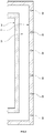
- FIG. 2 shows a vertical sectional view through the walls of a melting vessel according to the invention, which has an outer wall 3, an inner wall 4 and a arranged between the outer wall 3 and inner wall 4 coolant channel 5.
- a plurality of measuring devices 8 at different heights, namely in a vertical row parallel to the interface of the inner wall to the melting chamber, arranged.
- FIG. 3 shows one compared to FIG. 2 enlarged vertical sectional view through a part of an inner wall of a melting vessel according to the invention.
- the inner wall of a melting vessel according to the invention shown here has a multiplicity of measuring devices 8.
- the measuring devices are arranged in measuring groups, wherein the measuring devices 8 within a measuring group have a substantially equal distance to the interface 9 between the inner wall and the melting chamber.
- a first measuring group shown here has measuring devices 8, which have a distance A to the boundary surface 9 between the inner wall and the melting space. The distance of this first measuring group to the interface 9 between the inner wall and the melting space is smaller than the distance A + C of a second measuring group to the same interface.
- FIG. 4 shows a vertical sectional view of a melting vessel according to the invention in the form of a mold. Shown are the electrode 1 and ingot 2 and slag zone 6 and molten metal or metal alloy 7. Further, a plurality of measuring devices 8 is shown here, which are arranged at different heights in the inner wall 4 and are represented by small circles. The arrows symbolize the feeding of the electrode 1 or the removal of the ingot 2 according to a preferred embodiment. Outside wall and coolant channel are not shown. Shown is an embodiment with a measuring set of measuring devices 8 in a vertical row to determine the position and height (H) of the slag zone 6. There are also several rows in a measuring group conceivable and according to the invention. The rows do not have to run vertically, but can also be arranged distributed over the melting vessel at the same distance to the melting chamber at different heights.
- FIG. 5 shows three diagrams marked A, B and C from left to right. All diagrams show the time in hours on the X-axis and the height of the mold in millimeters on the Y-axis. All three diagrams show measurement results from a single melting process.
- Diagram A shows the measured temperature of measuring devices of a Measuring group with a short distance to the melting chamber.
- Diagram B shows the measured temperature of a measuring group with a slightly greater distance to the melting chamber. The lighter areas indicate a higher temperature than the darker areas.
- the diagram C shows the heat balance in the form of heat flux densities over the height of the mold. Regions of higher heat flux density are shown brighter than those with lower heat flux densities.
Landscapes
- Engineering & Computer Science (AREA)
- Mechanical Engineering (AREA)
- Chemical & Material Sciences (AREA)
- Organic Chemistry (AREA)
- Materials Engineering (AREA)
- Metallurgy (AREA)
- Manufacturing & Machinery (AREA)
- Physics & Mathematics (AREA)
- General Physics & Mathematics (AREA)
- Manufacture And Refinement Of Metals (AREA)
- Continuous Casting (AREA)
- Vertical, Hearth, Or Arc Furnaces (AREA)
- Waste-Gas Treatment And Other Accessory Devices For Furnaces (AREA)
- Furnace Details (AREA)
Claims (22)
- Procédé de fusion sous laitier électroconducteur de métaux ou alliages métalliques
dans un récipient de fusion avec au moins une paroi intérieure (4) et un espace de fusion délimité par la paroi intérieure (4), de sorte qu'une surface de délimitation (9) est présente entre la paroi intérieure (4) et l'espace de fusion,
avec les étapes de :A. mise à disposition d'au moins une électrode (1) du métal à fondre ou de l'alliage métallique à fondre dans le récipient de fusion,B. mise à disposition de laitier dans le récipient de fusion,C. fusion de l'électrode (1), de sorte que le métal ou l'alliage métallique fondu passe à travers une zone de laitier (6) et se fige en un lingot (2),caractérisé en ce que
le récipient de fusion présente des dispositifs de mesure (8) pour la mesure de la température et les dispositifs de mesure (8) sont agencés en au moins deux groupes de mesure,
dans lequel les dispositifs de mesure (8) présentent, à l'intérieur d'un groupe de mesure, une même distance par rapport à la surface de délimitation (9) entre paroi intérieure (4) et espace de fusion
et la distance par rapport à la surface de délimitation (9) entre paroi intérieure (4) et espace de fusion se distingue entre les dispositifs de mesure (8) de différents groupes de mesure,
et des dispositifs de mesure (8) sont agencés à l'intérieur d'un groupe de mesure à différentes hauteurs,
le récipient de fusion présente une paroi extérieure (3) et un canal de réfrigérant (5) s'étendant entre paroi extérieure (3) et paroi intérieure (4) et
le groupe de mesure, qui présente la plus petite distance par rapport à la surface de délimitation paroi intérieure/espace de fusion comparée à d'autres groupes de mesure, est agencé au milieu de la paroi intérieure (4)
dans lequel à l'aide des informations obtenues par le biais des dispositifs de mesure (8), un bilan thermique est établi. - Procédé selon la revendication 1, dans lequel le lingot (2) est retiré du récipient de fusion pendant la fusion et/ou le récipient de fusion est soulevé en mouvement relatif par rapport au lingot (2) croissant.
- Procédé selon la revendication 2, dans lequel la vitesse de retrait ou de soulèvement est au minimum de 0,01 cm/min et au maximum de 1,0 cm/min.
- Procédé selon la revendication 2 ou 3, dans lequel le produit de la vitesse de retrait ou de soulèvement avec le diamètre intérieur du récipient de fusion est au minimum de 1000 et au maximum de 5 000 mm2/min.
- Procédé selon au moins l'une quelconque des revendications précédentes, dans lequel la position de la zone de laitier (6) dans le récipient de fusion est déterminée pendant la fusion par le biais de dispositifs de mesure (8).
- Procédé selon la revendication 5, dans lequel la hauteur de la zone de laitier (6) dans le récipient de fusion est déterminée pendant la fusion par le biais de dispositifs de mesure (8).
- Procédé selon la revendication 5 ou 6, dans lequel la position déterminée de la zone de laitier (6) est comparée avec une position de consigne et dans le cas d'un écart de la position de la zone de laitier (6) de la position de consigne, il s'ensuit un effet sur la position de la zone de laitier (6).
- Procédé selon la revendication 7, dans lequel dans le cas d'un écart de la position de la zone de laitier (6) vers le bas, il s'ensuit une augmentation du taux de fusion et/ou un ralentissement du retrait du lingot (2) du récipient de fusion ou du soulèvement du récipient de fusion.
- Procédé selon la revendication 7 ou 8, dans lequel dans le cas d'un écart de la position de la zone de laitier (6) vers le haut, il s'ensuit une réduction du taux de fusion et/ou une accélération du retrait du lingot (2) du récipient de fusion ou du soulèvement du récipient de fusion.
- Procédé selon au moins l'une quelconque des revendications 6 à 9, dans lequel la hauteur de laitier est comparée avec une hauteur de consigne et dans le cas d'un écart de la hauteur de la zone de laitier vers le bas, du matériau de laitier est rajouté.
- Procédé selon la revendication 5, dans lequel la profondeur d'immersion de l'électrode (1) dans la zone de laitier (6) et/ou la quantité du dosage de laitier est corrigée en fonction du bilan thermique.
- Procédé selon au moins l'une quelconque des revendications précédentes, dans lequel la distance verticale entre les surfaces de délimitation lingot/bain métallique et bain métallique/laitier est au maximum le double du diamètre en coupe transversale du lingot fabriqué.
- Procédé selon au moins l'une quelconque des revendications précédentes, dans lequel le taux de fusion ne dépasse pas la valeur de 2,5 kg/h multipliée par le diamètre en coupe transversale du lingot fabriqué en millimètres.
- Récipient de fusion pour la fusion sous laitier électroconducteur de métaux ou alliages métalliques, avec au moins une paroi intérieure (4) et un espace de fusion délimité par la paroi intérieure (4), de sorte qu'une surface de délimitation (9) est présente entre paroi intérieure (4) et espace de fusion, caractérisé en ce que
le récipient de fusion présente des dispositifs de mesure (8) pour la mesure de la température et les dispositifs de mesure (8) sont agencés en au moins deux groupes de mesure,
dans lequel les dispositifs de mesure (8) présentent, à l'intérieur d'un groupe de mesure, la même distance par rapport à la surface de délimitation (9) entre paroi intérieure (4) et espace de fusion
et la distance par rapport à la surface de délimitation (9) entre paroi intérieure (4) et espace de fusion se distingue entre les dispositifs de mesure (8) de différents groupes de mesure,
et des dispositifs de mesure (8) sont agencés à l'intérieur d'un groupe de mesure à différentes hauteurs,
le récipient de fusion présente une paroi extérieure (3) et un canal de réfrigérant (5) s'étendant entre paroi extérieure (3) et paroi intérieure (4) et
le groupe de mesure, qui présente la plus petite distance par rapport à la surface de délimitation paroi intérieure/espace de fusion comparée à d'autres groupes de mesure, est agencé au milieu de la paroi intérieure (4). - Récipient de fusion selon la revendication 14, dans lequel les dispositifs de mesure (8) sont agencés dans la paroi intérieure (4) du récipient de fusion.
- Récipient de fusion selon la revendication 14 ou 15, dans lequel les dispositifs de mesure (8) sont des thermocouples.
- Récipient de fusion selon au moins l'une quelconque des revendications précédentes 14 à 16, dans lequel un premier groupe de mesure a une distance A par rapport à la surface de délimitation (9) entre paroi intérieure (4) et espace de fusion, qui est inférieure à la distance A+C d'un deuxième groupe de mesure par rapport à la même surface de délimitation.
- Récipient de fusion selon au moins l'une quelconque des revendications précédentes 14 à 17, dans lequel la distance de dispositifs de mesure adjacents à l'intérieur d'un groupe de mesure est minimale, là où la surface de délimitation bain métallique/laitier et/ou laitier/phase gazeuse est agencée lors du fonctionnement du récipient de fusion.
- Récipient de fusion selon au moins l'une quelconque des revendications précédentes 14 à 18, dans lequel une distance C horizontale entre les dispositifs de mesure (8) d'un premier groupe de mesure par rapport aux dispositifs de mesure (8) d'un deuxième groupe de mesure est d'au moins 3 mm.
- Récipient de fusion selon au moins l'une quelconque des revendications précédentes 14 à 19, dans lequel un dispositif de mesure correspondant d'un autre groupe de mesure est prévu à la même hauteur pour chaque dispositif de mesure d'un groupe de mesure.
- Récipient de fusion selon au moins l'une quelconque des revendications précédentes 14 à 20, dans lequel le nombre de dispositifs de mesure par groupe de mesure est d'au moins cinq.
- Utilisation d'un récipient de fusion selon l'une quelconque des revendications 14 à 21 dans un procédé de fusion sous laitier électroconducteur.
Priority Applications (1)
| Application Number | Priority Date | Filing Date | Title |
|---|---|---|---|
| SI201730034T SI3268149T1 (sl) | 2016-05-25 | 2017-05-23 | Postopek električnega pretaljevanja pod žlindro in talilni kotel |
Applications Claiming Priority (2)
| Application Number | Priority Date | Filing Date | Title |
|---|---|---|---|
| DE102016109712 | 2016-05-25 | ||
| PCT/EP2017/062450 WO2017202857A1 (fr) | 2016-05-25 | 2017-05-23 | Procédé de fusion sous laitier électroconducteur et récipient de fusion |
Publications (2)
| Publication Number | Publication Date |
|---|---|
| EP3268149A1 EP3268149A1 (fr) | 2018-01-17 |
| EP3268149B1 true EP3268149B1 (fr) | 2019-01-30 |
Family
ID=58994904
Family Applications (1)
| Application Number | Title | Priority Date | Filing Date |
|---|---|---|---|
| EP17727527.8A Active EP3268149B1 (fr) | 2016-05-25 | 2017-05-23 | Procédé de fusion sous laitier électroconducteur et récipient de fusion |
Country Status (7)
| Country | Link |
|---|---|
| US (1) | US10563286B2 (fr) |
| EP (1) | EP3268149B1 (fr) |
| JP (1) | JP7018405B2 (fr) |
| CN (1) | CN109789476B (fr) |
| SI (1) | SI3268149T1 (fr) |
| TR (1) | TR201904907T4 (fr) |
| WO (1) | WO2017202857A1 (fr) |
Citations (2)
| Publication number | Priority date | Publication date | Assignee | Title |
|---|---|---|---|---|
| DE19956577A1 (de) * | 1999-11-25 | 2001-05-31 | Sms Demag Ag | Verfahren zum Stranggießen von Brammen, insbesondere von Dünnbrammen, sowie eine Vorrichtung zu dessen Durchführung |
| DE102011114556A1 (de) * | 2011-09-30 | 2013-04-04 | Egon Evertz Kg (Gmbh & Co.) | Kupfer-Kokille oder Kupfer-Kokillenplatte zum Stranggießen von Metallen oder Metalllegierungen |
Family Cites Families (9)
| Publication number | Priority date | Publication date | Assignee | Title |
|---|---|---|---|---|
| US4320656A (en) * | 1980-07-28 | 1982-03-23 | United States Steel Corporation | Thermocouple apparatus for indicating liquid level in a container |
| JPH0639637B2 (ja) | 1986-05-30 | 1994-05-25 | 大同特殊鋼株式会社 | エレクトロスラグ再溶解炉 |
| JPS6372837A (ja) * | 1986-09-16 | 1988-04-02 | Daido Steel Co Ltd | エレクトロスラグ再溶解用るつぼ |
| DE4207694A1 (de) | 1992-03-11 | 1993-09-16 | Leybold Durferrit Gmbh | Vorrichtung fuer die herstellung von metallen und metall-legierungen hoher reinheit |
| CN101691634A (zh) * | 2009-09-08 | 2010-04-07 | 沈阳华盛冶金技术与装备有限责任公司 | 一种保护气氛电渣连铸炉 |
| AT509736B1 (de) | 2010-05-14 | 2012-03-15 | Inteco Special Melting Technologies Gmbh | Verfahren und vorrichtung zur kontinuierlichen erfassung des schlackenniveaus in esu-anlagen mit kurzen gleitkokillen |
| CN101905296B (zh) * | 2010-08-20 | 2012-05-09 | 东北大学 | 一种液态电渣连铸渣池液面的控制装置及方法 |
| EP2422900A1 (fr) * | 2010-08-26 | 2012-02-29 | SMS Concast AG | Agencement pour mesurer les paramètres physiques dans des lingotières de coulée en continu |
| CN104330411B (zh) * | 2014-11-10 | 2017-05-10 | 东北大学 | 一种动态观测模拟电渣重熔过程熔滴行为的装置及方法 |
-
2017
- 2017-05-23 US US16/302,880 patent/US10563286B2/en active Active
- 2017-05-23 JP JP2018561514A patent/JP7018405B2/ja active Active
- 2017-05-23 CN CN201780032608.4A patent/CN109789476B/zh active Active
- 2017-05-23 TR TR2019/04907T patent/TR201904907T4/tr unknown
- 2017-05-23 SI SI201730034T patent/SI3268149T1/sl unknown
- 2017-05-23 WO PCT/EP2017/062450 patent/WO2017202857A1/fr not_active Ceased
- 2017-05-23 EP EP17727527.8A patent/EP3268149B1/fr active Active
Patent Citations (2)
| Publication number | Priority date | Publication date | Assignee | Title |
|---|---|---|---|---|
| DE19956577A1 (de) * | 1999-11-25 | 2001-05-31 | Sms Demag Ag | Verfahren zum Stranggießen von Brammen, insbesondere von Dünnbrammen, sowie eine Vorrichtung zu dessen Durchführung |
| DE102011114556A1 (de) * | 2011-09-30 | 2013-04-04 | Egon Evertz Kg (Gmbh & Co.) | Kupfer-Kokille oder Kupfer-Kokillenplatte zum Stranggießen von Metallen oder Metalllegierungen |
Also Published As
| Publication number | Publication date |
|---|---|
| CN109789476B (zh) | 2021-10-12 |
| JP2019516559A (ja) | 2019-06-20 |
| JP7018405B2 (ja) | 2022-02-10 |
| WO2017202857A1 (fr) | 2017-11-30 |
| US10563286B2 (en) | 2020-02-18 |
| US20190144969A1 (en) | 2019-05-16 |
| SI3268149T1 (sl) | 2019-05-31 |
| EP3268149A1 (fr) | 2018-01-17 |
| CN109789476A (zh) | 2019-05-21 |
| TR201904907T4 (tr) | 2019-05-21 |
Similar Documents
| Publication | Publication Date | Title |
|---|---|---|
| DE69931141T2 (de) | Schmelzverfahren in einer Induktion-Kalt-Schmelz-Tiegelanlage | |
| DE60020505T2 (de) | Schmelzflüssiger Metallbadofen und Giessverfahren | |
| EP0786531B1 (fr) | Procédé et dispositif pour la refusion de métaux sous forme de barres | |
| DE10156336A1 (de) | Verfahren zur Herstellung von Legierungs-Ingots | |
| DE19956577A1 (de) | Verfahren zum Stranggießen von Brammen, insbesondere von Dünnbrammen, sowie eine Vorrichtung zu dessen Durchführung | |
| DE3590783C2 (de) | Verfahren zur Herstellung von Hohlbl¦cken durch Elektroschlackeumschmelzen und Vorrichtung f}r dessen Durchf}hrung | |
| EP2386366B1 (fr) | Procédé et dispositif d'établissement continu du niveau de scories dans des installations de refusion par laitier électrique à l'aide de lingotières courtes | |
| AT509495A1 (de) | Verfahren und anlage zur herstellung hohler umschmelzblöcke | |
| DE69311010T2 (de) | Verfahren und Vorrichtung zum Bestimmen der Position von Grenzflächen zwischen Flüssigkeiten | |
| EP3268149B1 (fr) | Procédé de fusion sous laitier électroconducteur et récipient de fusion | |
| DE4420697A1 (de) | Verfahren und Vorrichtung zum Stranggießen eines Verbundmetallstranges | |
| DE10154727A1 (de) | Verfahren zum Herstellen von Blöcken oder Strängen aus Metall durch Abschmelzen von Elektroden sowie Vorrichtung zu dessen Durchführung | |
| DE2844557A1 (de) | System zum hersttellen und giessen von fluessigem silicium | |
| DE112016007049T5 (de) | GIEßLEHRE UND GIEßVERFAHREN UNTER VERWENDUNG DERSELBEN | |
| DE2829355C2 (de) | Vorrichtung zur Bestimmung der Höhe einer Flüßigkeitsoberfläche in einem Behälter | |
| DE2001256B2 (de) | Vorrichtung zur herstellung von bloecken | |
| DE2908795C2 (de) | Vorrichtung zum Aufbringen eines Schutzstoffs auf den Badspiegel innerhalb einer elektromagnetischen Stranggießkokille | |
| EP2480356B1 (fr) | Procédé et dispositif pour couler une masse métallique fondue avec une machine de coulée en continu | |
| DE2545162C3 (de) | Verfahren und Vorrichtung zum Regeln des Elektroschlackeumschmelzens von Metallen | |
| DE2632863C2 (de) | Einrichtung zur Herstellung von großtonnagigen Metallblöcken durch Elektroschlackenumschmelzen | |
| DE10154721A1 (de) | Verfahren zum Herstellen von Blöcken oder Strängen aus Metall durch Abschmelzen von Elektroden sowie Vorrichtung zu dessen Durchführung | |
| DE4417221C2 (de) | Verfahren zum Stranggießen eines Metallstranges | |
| EP3619172B1 (fr) | Élément pour fusion de verre | |
| DE2449096A1 (de) | Verfahren und vorrichtung zur veredelung von metallen | |
| Wenzl | Structure and casting technology of anodes in copper metallurgy |
Legal Events
| Date | Code | Title | Description |
|---|---|---|---|
| STAA | Information on the status of an ep patent application or granted ep patent |
Free format text: STATUS: UNKNOWN |
|
| STAA | Information on the status of an ep patent application or granted ep patent |
Free format text: STATUS: THE INTERNATIONAL PUBLICATION HAS BEEN MADE |
|
| PUAI | Public reference made under article 153(3) epc to a published international application that has entered the european phase |
Free format text: ORIGINAL CODE: 0009012 |
|
| STAA | Information on the status of an ep patent application or granted ep patent |
Free format text: STATUS: REQUEST FOR EXAMINATION WAS MADE |
|
| 17P | Request for examination filed |
Effective date: 20170906 |
|
| AK | Designated contracting states |
Kind code of ref document: A1 Designated state(s): AL AT BE BG CH CY CZ DE DK EE ES FI FR GB GR HR HU IE IS IT LI LT LU LV MC MK MT NL NO PL PT RO RS SE SI SK SM TR |
|
| AX | Request for extension of the european patent |
Extension state: BA ME |
|
| STAA | Information on the status of an ep patent application or granted ep patent |
Free format text: STATUS: EXAMINATION IS IN PROGRESS |
|
| 17Q | First examination report despatched |
Effective date: 20180319 |
|
| GRAP | Despatch of communication of intention to grant a patent |
Free format text: ORIGINAL CODE: EPIDOSNIGR1 |
|
| STAA | Information on the status of an ep patent application or granted ep patent |
Free format text: STATUS: GRANT OF PATENT IS INTENDED |
|
| RIC1 | Information provided on ipc code assigned before grant |
Ipc: F27B 3/08 20060101ALI20180920BHEP Ipc: B22D 2/00 20060101AFI20180920BHEP Ipc: B22D 23/10 20060101ALI20180920BHEP Ipc: B22D 11/18 20060101ALI20180920BHEP Ipc: F27D 19/00 20060101ALI20180920BHEP Ipc: G01K 13/02 20060101ALI20180920BHEP Ipc: C22B 9/18 20060101ALI20180920BHEP Ipc: F27D 21/00 20060101ALI20180920BHEP Ipc: B22D 11/20 20060101ALI20180920BHEP |
|
| INTG | Intention to grant announced |
Effective date: 20181002 |
|
| GRAS | Grant fee paid |
Free format text: ORIGINAL CODE: EPIDOSNIGR3 |
|
| GRAA | (expected) grant |
Free format text: ORIGINAL CODE: 0009210 |
|
| STAA | Information on the status of an ep patent application or granted ep patent |
Free format text: STATUS: THE PATENT HAS BEEN GRANTED |
|
| DAV | Request for validation of the european patent (deleted) | ||
| DAX | Request for extension of the european patent (deleted) | ||
| AK | Designated contracting states |
Kind code of ref document: B1 Designated state(s): AL AT BE BG CH CY CZ DE DK EE ES FI FR GB GR HR HU IE IS IT LI LT LU LV MC MK MT NL NO PL PT RO RS SE SI SK SM TR |
|
| REG | Reference to a national code |
Ref country code: GB Ref legal event code: FG4D Free format text: NOT ENGLISH |
|
| REG | Reference to a national code |
Ref country code: CH Ref legal event code: EP |
|
| REG | Reference to a national code |
Ref country code: AT Ref legal event code: REF Ref document number: 1092834 Country of ref document: AT Kind code of ref document: T Effective date: 20190215 |
|
| REG | Reference to a national code |
Ref country code: IE Ref legal event code: FG4D Free format text: LANGUAGE OF EP DOCUMENT: GERMAN |
|
| REG | Reference to a national code |
Ref country code: DE Ref legal event code: R096 Ref document number: 502017000724 Country of ref document: DE |
|
| REG | Reference to a national code |
Ref country code: SE Ref legal event code: TRGR |
|
| REG | Reference to a national code |
Ref country code: LT Ref legal event code: MG4D |
|
| REG | Reference to a national code |
Ref country code: NL Ref legal event code: MP Effective date: 20190130 |
|
| PG25 | Lapsed in a contracting state [announced via postgrant information from national office to epo] |
Ref country code: LT Free format text: LAPSE BECAUSE OF FAILURE TO SUBMIT A TRANSLATION OF THE DESCRIPTION OR TO PAY THE FEE WITHIN THE PRESCRIBED TIME-LIMIT Effective date: 20190130 Ref country code: PL Free format text: LAPSE BECAUSE OF FAILURE TO SUBMIT A TRANSLATION OF THE DESCRIPTION OR TO PAY THE FEE WITHIN THE PRESCRIBED TIME-LIMIT Effective date: 20190130 Ref country code: NO Free format text: LAPSE BECAUSE OF FAILURE TO SUBMIT A TRANSLATION OF THE DESCRIPTION OR TO PAY THE FEE WITHIN THE PRESCRIBED TIME-LIMIT Effective date: 20190430 Ref country code: PT Free format text: LAPSE BECAUSE OF FAILURE TO SUBMIT A TRANSLATION OF THE DESCRIPTION OR TO PAY THE FEE WITHIN THE PRESCRIBED TIME-LIMIT Effective date: 20190530 Ref country code: ES Free format text: LAPSE BECAUSE OF FAILURE TO SUBMIT A TRANSLATION OF THE DESCRIPTION OR TO PAY THE FEE WITHIN THE PRESCRIBED TIME-LIMIT Effective date: 20190130 Ref country code: FI Free format text: LAPSE BECAUSE OF FAILURE TO SUBMIT A TRANSLATION OF THE DESCRIPTION OR TO PAY THE FEE WITHIN THE PRESCRIBED TIME-LIMIT Effective date: 20190130 |
|
| PG25 | Lapsed in a contracting state [announced via postgrant information from national office to epo] |
Ref country code: BG Free format text: LAPSE BECAUSE OF FAILURE TO SUBMIT A TRANSLATION OF THE DESCRIPTION OR TO PAY THE FEE WITHIN THE PRESCRIBED TIME-LIMIT Effective date: 20190430 Ref country code: GR Free format text: LAPSE BECAUSE OF FAILURE TO SUBMIT A TRANSLATION OF THE DESCRIPTION OR TO PAY THE FEE WITHIN THE PRESCRIBED TIME-LIMIT Effective date: 20190501 Ref country code: LV Free format text: LAPSE BECAUSE OF FAILURE TO SUBMIT A TRANSLATION OF THE DESCRIPTION OR TO PAY THE FEE WITHIN THE PRESCRIBED TIME-LIMIT Effective date: 20190130 Ref country code: RS Free format text: LAPSE BECAUSE OF FAILURE TO SUBMIT A TRANSLATION OF THE DESCRIPTION OR TO PAY THE FEE WITHIN THE PRESCRIBED TIME-LIMIT Effective date: 20190130 Ref country code: NL Free format text: LAPSE BECAUSE OF FAILURE TO SUBMIT A TRANSLATION OF THE DESCRIPTION OR TO PAY THE FEE WITHIN THE PRESCRIBED TIME-LIMIT Effective date: 20190130 Ref country code: IS Free format text: LAPSE BECAUSE OF FAILURE TO SUBMIT A TRANSLATION OF THE DESCRIPTION OR TO PAY THE FEE WITHIN THE PRESCRIBED TIME-LIMIT Effective date: 20190530 Ref country code: HR Free format text: LAPSE BECAUSE OF FAILURE TO SUBMIT A TRANSLATION OF THE DESCRIPTION OR TO PAY THE FEE WITHIN THE PRESCRIBED TIME-LIMIT Effective date: 20190130 |
|
| PG25 | Lapsed in a contracting state [announced via postgrant information from national office to epo] |
Ref country code: SK Free format text: LAPSE BECAUSE OF FAILURE TO SUBMIT A TRANSLATION OF THE DESCRIPTION OR TO PAY THE FEE WITHIN THE PRESCRIBED TIME-LIMIT Effective date: 20190130 Ref country code: AL Free format text: LAPSE BECAUSE OF FAILURE TO SUBMIT A TRANSLATION OF THE DESCRIPTION OR TO PAY THE FEE WITHIN THE PRESCRIBED TIME-LIMIT Effective date: 20190130 Ref country code: CZ Free format text: LAPSE BECAUSE OF FAILURE TO SUBMIT A TRANSLATION OF THE DESCRIPTION OR TO PAY THE FEE WITHIN THE PRESCRIBED TIME-LIMIT Effective date: 20190130 Ref country code: RO Free format text: LAPSE BECAUSE OF FAILURE TO SUBMIT A TRANSLATION OF THE DESCRIPTION OR TO PAY THE FEE WITHIN THE PRESCRIBED TIME-LIMIT Effective date: 20190130 Ref country code: DK Free format text: LAPSE BECAUSE OF FAILURE TO SUBMIT A TRANSLATION OF THE DESCRIPTION OR TO PAY THE FEE WITHIN THE PRESCRIBED TIME-LIMIT Effective date: 20190130 Ref country code: EE Free format text: LAPSE BECAUSE OF FAILURE TO SUBMIT A TRANSLATION OF THE DESCRIPTION OR TO PAY THE FEE WITHIN THE PRESCRIBED TIME-LIMIT Effective date: 20190130 |
|
| REG | Reference to a national code |
Ref country code: DE Ref legal event code: R097 Ref document number: 502017000724 Country of ref document: DE |
|
| PG25 | Lapsed in a contracting state [announced via postgrant information from national office to epo] |
Ref country code: SM Free format text: LAPSE BECAUSE OF FAILURE TO SUBMIT A TRANSLATION OF THE DESCRIPTION OR TO PAY THE FEE WITHIN THE PRESCRIBED TIME-LIMIT Effective date: 20190130 |
|
| PLBE | No opposition filed within time limit |
Free format text: ORIGINAL CODE: 0009261 |
|
| STAA | Information on the status of an ep patent application or granted ep patent |
Free format text: STATUS: NO OPPOSITION FILED WITHIN TIME LIMIT |
|
| 26N | No opposition filed |
Effective date: 20191031 |
|
| PG25 | Lapsed in a contracting state [announced via postgrant information from national office to epo] |
Ref country code: MC Free format text: LAPSE BECAUSE OF FAILURE TO SUBMIT A TRANSLATION OF THE DESCRIPTION OR TO PAY THE FEE WITHIN THE PRESCRIBED TIME-LIMIT Effective date: 20190130 |
|
| PG25 | Lapsed in a contracting state [announced via postgrant information from national office to epo] |
Ref country code: LU Free format text: LAPSE BECAUSE OF NON-PAYMENT OF DUE FEES Effective date: 20190523 |
|
| PG25 | Lapsed in a contracting state [announced via postgrant information from national office to epo] |
Ref country code: IE Free format text: LAPSE BECAUSE OF NON-PAYMENT OF DUE FEES Effective date: 20190523 |
|
| PG25 | Lapsed in a contracting state [announced via postgrant information from national office to epo] |
Ref country code: FR Free format text: LAPSE BECAUSE OF NON-PAYMENT OF DUE FEES Effective date: 20190531 |
|
| PG25 | Lapsed in a contracting state [announced via postgrant information from national office to epo] |
Ref country code: LI Free format text: LAPSE BECAUSE OF NON-PAYMENT OF DUE FEES Effective date: 20200531 Ref country code: CH Free format text: LAPSE BECAUSE OF NON-PAYMENT OF DUE FEES Effective date: 20200531 |
|
| PG25 | Lapsed in a contracting state [announced via postgrant information from national office to epo] |
Ref country code: CY Free format text: LAPSE BECAUSE OF FAILURE TO SUBMIT A TRANSLATION OF THE DESCRIPTION OR TO PAY THE FEE WITHIN THE PRESCRIBED TIME-LIMIT Effective date: 20190130 |
|
| PG25 | Lapsed in a contracting state [announced via postgrant information from national office to epo] |
Ref country code: MT Free format text: LAPSE BECAUSE OF FAILURE TO SUBMIT A TRANSLATION OF THE DESCRIPTION OR TO PAY THE FEE WITHIN THE PRESCRIBED TIME-LIMIT Effective date: 20190130 Ref country code: HU Free format text: LAPSE BECAUSE OF FAILURE TO SUBMIT A TRANSLATION OF THE DESCRIPTION OR TO PAY THE FEE WITHIN THE PRESCRIBED TIME-LIMIT; INVALID AB INITIO Effective date: 20170523 |
|
| PG25 | Lapsed in a contracting state [announced via postgrant information from national office to epo] |
Ref country code: MK Free format text: LAPSE BECAUSE OF FAILURE TO SUBMIT A TRANSLATION OF THE DESCRIPTION OR TO PAY THE FEE WITHIN THE PRESCRIBED TIME-LIMIT Effective date: 20190130 |
|
| P01 | Opt-out of the competence of the unified patent court (upc) registered |
Effective date: 20230524 |
|
| PGFP | Annual fee paid to national office [announced via postgrant information from national office to epo] |
Ref country code: DE Payment date: 20250519 Year of fee payment: 9 |
|
| PGFP | Annual fee paid to national office [announced via postgrant information from national office to epo] |
Ref country code: GB Payment date: 20250522 Year of fee payment: 9 |
|
| PGFP | Annual fee paid to national office [announced via postgrant information from national office to epo] |
Ref country code: BE Payment date: 20250520 Year of fee payment: 9 Ref country code: IT Payment date: 20250530 Year of fee payment: 9 |
|
| PGFP | Annual fee paid to national office [announced via postgrant information from national office to epo] |
Ref country code: AT Payment date: 20250519 Year of fee payment: 9 |
|
| PGFP | Annual fee paid to national office [announced via postgrant information from national office to epo] |
Ref country code: TR Payment date: 20250515 Year of fee payment: 9 |
|
| PGFP | Annual fee paid to national office [announced via postgrant information from national office to epo] |
Ref country code: SE Payment date: 20250522 Year of fee payment: 9 Ref country code: SI Payment date: 20250512 Year of fee payment: 9 |