EP3268242B1 - Bordsystem zum wiederaufladen von bordbatterien in einem elektrofahrzeug - Google Patents
Bordsystem zum wiederaufladen von bordbatterien in einem elektrofahrzeug Download PDFInfo
- Publication number
- EP3268242B1 EP3268242B1 EP16723790.8A EP16723790A EP3268242B1 EP 3268242 B1 EP3268242 B1 EP 3268242B1 EP 16723790 A EP16723790 A EP 16723790A EP 3268242 B1 EP3268242 B1 EP 3268242B1
- Authority
- EP
- European Patent Office
- Prior art keywords
- flywheel
- generator
- rod
- secured
- hollow
- Prior art date
- Legal status (The legal status is an assumption and is not a legal conclusion. Google has not performed a legal analysis and makes no representation as to the accuracy of the status listed.)
- Not-in-force
Links
Images
Classifications
-
- B—PERFORMING OPERATIONS; TRANSPORTING
- B60—VEHICLES IN GENERAL
- B60L—PROPULSION OF ELECTRICALLY-PROPELLED VEHICLES; SUPPLYING ELECTRIC POWER FOR AUXILIARY EQUIPMENT OF ELECTRICALLY-PROPELLED VEHICLES; ELECTRODYNAMIC BRAKE SYSTEMS FOR VEHICLES IN GENERAL; MAGNETIC SUSPENSION OR LEVITATION FOR VEHICLES; MONITORING OPERATING VARIABLES OF ELECTRICALLY-PROPELLED VEHICLES; ELECTRIC SAFETY DEVICES FOR ELECTRICALLY-PROPELLED VEHICLES
- B60L50/00—Electric propulsion with power supplied within the vehicle
- B60L50/30—Electric propulsion with power supplied within the vehicle using propulsion power stored mechanically, e.g. in fly-wheels
-
- B—PERFORMING OPERATIONS; TRANSPORTING
- B60—VEHICLES IN GENERAL
- B60L—PROPULSION OF ELECTRICALLY-PROPELLED VEHICLES; SUPPLYING ELECTRIC POWER FOR AUXILIARY EQUIPMENT OF ELECTRICALLY-PROPELLED VEHICLES; ELECTRODYNAMIC BRAKE SYSTEMS FOR VEHICLES IN GENERAL; MAGNETIC SUSPENSION OR LEVITATION FOR VEHICLES; MONITORING OPERATING VARIABLES OF ELECTRICALLY-PROPELLED VEHICLES; ELECTRIC SAFETY DEVICES FOR ELECTRICALLY-PROPELLED VEHICLES
- B60L2200/00—Type of vehicles
- B60L2200/10—Air crafts
-
- B—PERFORMING OPERATIONS; TRANSPORTING
- B60—VEHICLES IN GENERAL
- B60L—PROPULSION OF ELECTRICALLY-PROPELLED VEHICLES; SUPPLYING ELECTRIC POWER FOR AUXILIARY EQUIPMENT OF ELECTRICALLY-PROPELLED VEHICLES; ELECTRODYNAMIC BRAKE SYSTEMS FOR VEHICLES IN GENERAL; MAGNETIC SUSPENSION OR LEVITATION FOR VEHICLES; MONITORING OPERATING VARIABLES OF ELECTRICALLY-PROPELLED VEHICLES; ELECTRIC SAFETY DEVICES FOR ELECTRICALLY-PROPELLED VEHICLES
- B60L2200/00—Type of vehicles
- B60L2200/26—Rail vehicles
-
- B—PERFORMING OPERATIONS; TRANSPORTING
- B60—VEHICLES IN GENERAL
- B60L—PROPULSION OF ELECTRICALLY-PROPELLED VEHICLES; SUPPLYING ELECTRIC POWER FOR AUXILIARY EQUIPMENT OF ELECTRICALLY-PROPELLED VEHICLES; ELECTRODYNAMIC BRAKE SYSTEMS FOR VEHICLES IN GENERAL; MAGNETIC SUSPENSION OR LEVITATION FOR VEHICLES; MONITORING OPERATING VARIABLES OF ELECTRICALLY-PROPELLED VEHICLES; ELECTRIC SAFETY DEVICES FOR ELECTRICALLY-PROPELLED VEHICLES
- B60L2200/00—Type of vehicles
- B60L2200/32—Waterborne vessels
-
- B—PERFORMING OPERATIONS; TRANSPORTING
- B60—VEHICLES IN GENERAL
- B60L—PROPULSION OF ELECTRICALLY-PROPELLED VEHICLES; SUPPLYING ELECTRIC POWER FOR AUXILIARY EQUIPMENT OF ELECTRICALLY-PROPELLED VEHICLES; ELECTRODYNAMIC BRAKE SYSTEMS FOR VEHICLES IN GENERAL; MAGNETIC SUSPENSION OR LEVITATION FOR VEHICLES; MONITORING OPERATING VARIABLES OF ELECTRICALLY-PROPELLED VEHICLES; ELECTRIC SAFETY DEVICES FOR ELECTRICALLY-PROPELLED VEHICLES
- B60L2200/00—Type of vehicles
- B60L2200/36—Vehicles designed to transport cargo, e.g. trucks
-
- Y—GENERAL TAGGING OF NEW TECHNOLOGICAL DEVELOPMENTS; GENERAL TAGGING OF CROSS-SECTIONAL TECHNOLOGIES SPANNING OVER SEVERAL SECTIONS OF THE IPC; TECHNICAL SUBJECTS COVERED BY FORMER USPC CROSS-REFERENCE ART COLLECTIONS [XRACs] AND DIGESTS
- Y02—TECHNOLOGIES OR APPLICATIONS FOR MITIGATION OR ADAPTATION AGAINST CLIMATE CHANGE
- Y02T—CLIMATE CHANGE MITIGATION TECHNOLOGIES RELATED TO TRANSPORTATION
- Y02T10/00—Road transport of goods or passengers
- Y02T10/60—Other road transportation technologies with climate change mitigation effect
- Y02T10/70—Energy storage systems for electromobility, e.g. batteries
Definitions
- This invention relates to the field of means of transport using electrical energy and its technology to move around.
- the first electric cars appeared around 1880 to be quickly supplanted thirty years later by the combustion engine car.
- the first years of the electric car's existence made it possible to put into perspective the characteristics responsible for its inability to maintain its market share.
- the problem raised or the challenge to be overcome is therefore that of regenerating or accessing the energy which is vital to it, increasing the efficiency of the batteries and consequently to extend the availability of this energy over time, thereby reducing the number of 'relay terminals' to reach the intended destination.
- the second challenge is to find a way to recharge the batteries as quickly as possible.
- the electric car can only truly exist by finding the solution to these two problems: the efficiency of recharging stations on the road network and the performance of unlimited recharging batteries.
- the techniques applied so far to recharge the batteries range from standard charging at home from a suitable outlet to occasional access to a broadband terminal in specific areas offering the service to happy owners through technological means. exploiting vehicle control mechanics developed to recover part of the energy released by the kinetic power of the moving vehicle.
- the vehicle uses the numerous braking instants during the journey and the periods of engine decompression (when the driver takes his foot off the accelerator or starts a descent) which activate various generator systems to produce a certain amount of electrical energy and partially regenerate the battery assembly.
- Another technology integrates into the vehicle's drive unit a generator coupled to the drive or engagement axis, the engine then having the dual function of moving the vehicle (and what it carries) and of driving the unit. generator in order to produce a certain quantity of electricity to compensate for that being consumed by the propellant motor, which must also meet the demands of the driver, the efforts and requirements of the route taken and the unforeseen circumstances of the route.
- the solution that we propose, the object of our invention is an on-board system according to claim capable of recharging the on-board batteries of a vehicle (and other means of transport with traction or electric propulsion) whether it is running ( moving) or stationary (immobilized).
- This on-board system includes a starter / generator motor connected to the assembly ble batteries which, in the production process, initially place in electronically pre-grammed rotation a flywheel whose speed is contained for safety reasons by a gear unit providing at the output an increased speed of rotation, recovered and redirected by a dedicated transmission shaft (to widen and extend the exploitation of the productive niche of the kinetic energy generated) towards the motor which then becomes a generator of electrical energy which is also stored in the on-board batteries.
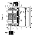
- the present invention is an electricity production system having a close relationship between the energy capacity of a motor acting as a starter (1 M /), of a flywheel (3) which it rotates and the motor (1 M /) turned generator (1 / G) producing electricity from the kinetic energy coming from the speed of rotation, from the flywheel (3), multiplied by mechanical conversion (5) .
- This system for recharging the on-board battery unit (8) can be placed in and used by a vehicle, an aircraft or other means of transport with electric propulsion or traction.
- the initial energy of our system depends on a motor (1 M / G) connected to the assembly batteries (8) on board and acting as a starter - or rotation accelerator when the system is already in operation - (1 M /) at the start of each production cycle.
- This same starter motor (1 M /) becomes a generator (1 / G) and electricity producer when it is then activated by the kinetic energy of the flywheel (3) which it has set in rotation.
- the two electromagnetic clutch units (2, 4) differ in their function; the first unit (2) contributes to transfer and transform the electric energy of the starter motor (1 M /) into kinetic energy; and the second unit (4), activating the speed converter (5, 5b) leading to the solid shaft (7) connected directly to the generator (1 / G).
- the kinetic energy of the flywheel (3) is transferred to the generator (1 / G) after reaching (by the starter motor (immediately deactivated) a pre-programmed maximum rotation speed.
- the gear unit (5) on the one hand protects the flywheel (3) by limiting its speed of rotation and on the other hand by multiplying by interposed gears (5a, 5b) the speed of rotation of the solid rod (7 ) integral with the generator (1 / G) to prolong the operation of the generator's productive speed zones over time.
- the two hollow rods at the ends (6a1, 6a4) have the particularity of being welded or made integral with the solid rod (7) by a key or a pin (washers respecting the distance between hollow rods and solid rod, if necessary) while the hollow rods (6a 2, 6a3) can rotate freely on the solid rod (7) by relying on ball bearings (or other means proposed by the industry).
- the transmission shaft (6, 7) is placed, reinforced and stabilized on a ball bearing (6b) in the anchorages of the bearings of the protective housing (12) summarily illustrated.
- Dwarf bearings (12a) complementary to the frame (12) placed above and below and in the course of the grooves cut in the flywheel (3) neutralize the possible positioning deviations due to the jolts and shocks suffered by the body of the vehicle.
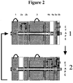
- the two rods of the shaft (6, 7) being torque transmitters have the function, at different times of the recharging process ( Fig. 2 -E1, 2), to ensure the entry into activity of one or more of the components (1 to 5).
- the solid rod (7) therefore carries and groups together all the elements of the system (1 to 5) themselves carried by the hollow rods (6a1, 6a2, 6a3, 6a4). One after another or with each other, they play the role assigned to them according to a cycle of electronically pre-programmed sequences (10, 11) following the information relayed by the tachometer sensors (9a). These components placed on the free hollow rods (6a2, 6a3) or linked (6a1, 6a4) engage, transfer, transmit, produce and disengage.
- the first plate (2a) of the electromagnetic clutch unit I (2) carried by the rod (6a) also supporting the engine (1M /) thus becomes integral with the activities of the engine / generator (1 M / G) fixed or securely welded to the solid rod (7).
- This plate (2a) therefore always rotates at the speed of the motor / generator (1 M / G), of the hollow rod (6a 1) and of the solid rod (7).
- the second plate (2b) of the clutch assembly I (2) fixed on the hollow rod (6a2), according to the programmed cycle sequence, can come into contact with the plate (2a) to which it is paired.
- the clutch plate (2b) is fixed to the left cylindrical wall of the flywheel (3) integral with the hollow rod (6a2) floating freely on the solid rod (7).
- the flywheel (3) links directly to the activated starter motor (1 M /) and is rotated.
- This contact between engine (1 M /) and flywheel (3) lasts the time to reach by acceleration of the starter motor (1 M /) the number of revolutions / minute registered in the pre circuit. programmed (10, 11) of the system and required by the generator (1 / G) - (still inactive) - to obtain an efficient output at the electrical production stage.
- the flywheel (3) is a mass of cylindrical shape centered on its longitudinal axis made of steel or other high-performance material selected taking into account the weight, the radius of the flywheel and its resistance and maximum speed before risk of breakage.
- the flywheel (3) Fixed on the hollow rod (6a2) and in free rotation on the solid rod (7), the flywheel (3) forms a block on its right wall with a second clutch plate (4b) belonging to the electromagnetic assembly II (4).
- the plate (4a) is carried by the hollow rod (6a 3) and firmly fixed to a disc (5a) carried by this same hollow rod (6a3) rotating outside the casing (or box ) of the gear unit (5), multiplier or speed converter of which it is an integral part.
- the kinetic energy of the freely rotating flywheel (3) with the hollow rod (6a2) and the hollow rod (6a3) is shared by contact of the plates (4b, 4a) of the clutch unit II (4) but after the prior disengagement of the plates (2a, 2b) from the clutch unit I (2).
- the multiplier (5) On activation of the clutch unit II (4), the multiplier (5) through a large toothed wheel inside the housing, extending and turning at the same speed as the disc (5a) and a series of intermediate gears, increases the speed of rotation of the solid rod (7) whose end opposite the generator (1 / G) is engaged in the 'driving' toothed wheel (5b) of the converter (5) to reach the speed of output required by the generator (1 / G), without modifying the speed of the flywheel (3).
- the solid rod (7) passes through the outer disc (5a) carried by the hollow rod (6a3) and the large internal toothed wheel, supported on the central extension of the disc (5a) and by ball bearings, on the vertical wall of the first opening of the housing, the solid rod (7) itself being supported at its end by a ball bearing on the outlet opening of the vertical wall of the housing grouping together the gear units (5).
- the electrical energy generated ( Fig. 2 -E2), the result of these successive operations is transferred to and stored in the battery assembly (8) to replace the energy consumed by the vehicle's electric propellant.
- the electricity production period ( Fig. 2 E2) continues until the process resumes ( Fig. 2 -E1) of our system, the speed of rotation brought to the generator then having reached an energy productivity threshold lower than the revs / sec parameters. required by the generator (1 / G) to replenish the batteries (8).
- the ON command (11) activates the starter motor (1 M /) and starts the program (10) of the battery recharging system (8).
- the driver then only has to start the electric motor, the vehicle's propellant, and hit the road to his destination.
- the first stage of the charging system ( Fig. 2 -E1), therefore starts the starter motor (1 M /) and almost simultaneously connects the plates (2a) and (2b) of the electromagnetic clutch I (2).
- the hollow rod (6a 1) integral with the transmission shaft (7) supports both the motor (1 M /) and the first plate (2a) of the clutch I (2).
- the flywheel (3) carried freely by the hollow rod (6a2) with the second plate (2b) fixed to its left wall are driven for a few tens of seconds by the starter motor (1 M /) - ( Fig. 2 -E1), the time to reach the speed of rotation required to ensure efficient productivity of the generator (1 / G), which must soon come into action (the speed rpm reached corresponding to the one preprogrammed electronically).
- the end of the first stage ( Fig. 2 -E1) of the process first disconnects the two plates (2a-2b) of the first clutch assembly I (2) leaving the flywheel (3) attached to the hollow rod (6a2) to freely rotate at full speed on the solid rod (7).
- the second and last stage of the cycle begins when the plates (4b, 4a) of the second set of electromagnetic clutch II (4) come into programmed contact and become one (4) - ( Fig. 2 -E2) establishing from the outer disc (5a) welded to the gear unit (5), the junction between the flywheel (3) and the gear unit, speed converter (5) including the 'driving' toothed wheel (5b) is integral with the hollow rod (6a4) itself integral with the solid rod (7) connected to the end opposite the motor which has become generator (1 / G).
- the driving wheel of the multiplier (5b) then increases the speed of rotation of the solid rod (7) without modifying the speed of the flywheel (3) carried by the rod (6a2).
- the moving mass thus remains within safe and acceptable limits of rotation.
- the multiplied speed transmitted to the solid rod (7) by the gear unit (5) and transferred directly to the generator (1 / G) it prolongs the exploitation of the productive field of the electricity generator over time. .
- the generator (1 / G) produces electrical energy which is then directed to and stored in the battery assembly (8).
- This new energy thus partly replaces the energy consumed by the electric motor, the vehicle's propellant.
- the flywheel (3) will drive the generator (1 / G) until it leaves the productive zone of the generator (eg 5000> 2500 rpm).
- the lower limit being known and programmed, once reached, terminates the electromagnetic contact of the second clutch assembly II (4) - ( Fig. 2 -E2) and while the flywheel (3) continues to rotate freely on the solid rod (7), the motor / generator unit (1 M / G) automatically resumes its function as a starter motor (1 M /) - ( Fig. 2 -E1).
- the first step of the production process ( Fig. 2 -E1) automatically reconcile and reconnect the trays (2a, 2b) of the first set of electromagnetic clutch I (2) and recommences the activation sequences of the components (1, 2, 3, 4, 5) of the system and the operation of recharging the batteries ( Fig. 2 - E1 and 2), purpose of this system which is our invention.
- this charging system is dissociated from the type of driving, the form of control, the mastery and the conceptual characteristics of the means of electric transport concerned, (e.g. power of the kinetic mass of the vehicle, the brakes, the motorization, etc.) this can be activated even when the vehicle is completely stationary (eg driver break, cinema exit, terminals all occupied, isolated areas, etc.).
- an alert signal warns occupants that a minimum of energy remains stored.
- recharging can then be carried out to replenish the batteries sufficiently and resume the journey to the nearest terminal. This system thus allows emergency troubleshooting far from all services.
- this system is a solution to comfortably distance and reduce the number of battery recharging stops from point A to point B.
- the secondary rail networks could use this system for small circuits and thus give isolated or poorly served localities access to the main networks by setting up basic rail routes for innovative motor wagons.
- This system could equip small or medium-sized electric propulsion planes (already in use) and operate in combination or without solar modules in order to extend their flight time.
- Our invention could also replace conventional generators to fill in the off-peak periods or serve as a complement to the comfort arrangements of modern homes using wind power and solar panels.
Landscapes
- Engineering & Computer Science (AREA)
- Power Engineering (AREA)
- Transportation (AREA)
- Mechanical Engineering (AREA)
- Electric Propulsion And Braking For Vehicles (AREA)
- Connection Of Motors, Electrical Generators, Mechanical Devices, And The Like (AREA)
Claims (9)
- System zum Aufladen von Batterien (8), die in einem Elektrofahrzeug mitgeführt werden, dadurch gekennzeichnet, dass es umfasst:- einen Motor/Generator (1 M/G), der dazu konfiguriert ist, gemäß einer Anlasserfunktion (1 M/) und einer Generatorfunktion (1 /G) zu funktionieren, wobei der Motor/Generator (1 M/G) an die Batterien (8) angeschlossen ist,- ein Schwungrad (3),- eine Anordnung von Rädern (5) und ein Zahnrad (5b) an dem Ausgang der Einheit von Rädern (5), wobei die Einheit von Rädern (5) eine Einheit von Rädern (5a) umfasst, die dazu dient, die Drehzahl des Schwungrads (3) zu verringern und die Drehzahl an dem Ausgang des Zahnrads (5b) zu vervielfachen, um die Nutzung der produktiven Drehzahlzonen des Generators (1 /G) in der Dauer zu verlängern,- zwei elektromagnetische Kupplungen (2, 4), wobei jede der elektromagnetischen Kupplungen an jedem der Enden des Schwungrads (3) befestigt ist und jeweils aus zwei Platten (2a, 2b; 4a, 4b) gebildet ist,∘ wobei die erste Kupplung es dem Motor/Generator (1 M/G) erlaubt, das Schwungrad (3) in Drehung zu versetzen, und∘ die zweite Kupplung (4) das Schwungrad (3) mit der Anordnung von Geschwindigkeitswandlerrädern (5) zu verbinden,- zwei Übertragungswellen (6, 7),∘ wobei eine erste Übertragungswelle (6) aus einem hohlen Außenschaft besteht, und∘ eine zweite Übertragungswelle aus einem massiven Innenschaft (7) besteht, der mit dem Zahnrad (5b) verbunden ist, um die Drehzahl, die von der Einheit von Rädern (5) erhöht wird, zu übernehmen und die entsprechende kinetische Energie zu dem Stromgenerator (1 /G), mit dem sie fest verbunden ist, umzulenken,wobei der hohle Außenschaft der ersten Übertragungswelle (6) und der massive Innenschaft (7) der zweiten Welle in dieselbe Richtung drehen,der hohle Außenschaft vier hohle Schäfte (6a1, 6a2, 6a3, 6a4) aufweist, die alle denselben Außen- und Innendurchmesser aufweisen, umfassend:▪ einen ersten hohlen Schaft (6a1), der mit dem massiven Schaft (7) fest verbunden ist und mit dem Motor/Generator (1 M/G) und der ersten Platte (2a) der ersten Kupplung (2) fest verbunden ist,▪ einen zweiten hohlen Schaft (6a2), der um den massiven Schaft (7) in Drehung frei und mit der zweiten Platte (2b) der ersten Kupplung (2), dem Schwungrad (3) und der ersten Platte (4b) der zweiten Kupplung (4) fest verbunden ist,▪ einen dritten hohlen Schaft (6a3), der um den massiven Schaft (7) in Drehung frei und mit der zweiten Platte (4a) der zweiten Kupplung (4) und einer Außenscheibe (5a) der Einheit von Rädern (5) fest verbunden ist,▪ einen vierten hohlen Schaft (6a4), der mit dem massiven Schaft (7) fest verbunden und mit dem Zahnrad (5b) der Einheit von Rädern (5) fest verbunden ist,- eine elektronische Programmiereinheit (10) und eine automatische Steuereinheit (11), die Drehzahlen der hohlen Schäfte (6a1, 6a2, 6a3, 6a4) empfangen, die von Drehzahlzählersensoren (9a) aufgezeichnet werden, und Drehzahlen, die von Sensoren, der Motor/Generator-Einheit (1 M/G), der Schwungscheibe (3) und dem Zahnrad (5b) berechnet oder gemessen werden, um das Stoppen und das Ingangsetzen des mitgeführten Batterieaufladesystems zu steuern,wobei das System dazu konfiguriert ist, dass die Aufladung der Batterien ausgeführt wird, ob das Elektrofahrzeug in Gang ist, das heißt in Bewegung, oder beim Stoppen, das heißt stillsteht.
- System nach Anspruch 1, dadurch gekennzeichnet, dass:- in der Anlasserfunktion (1 M/) der Motor/Generator (1 M/G) dazu konfiguriert ist, während eines ersten Schritts das Schwungrad (3) zu starten und in Drehung anzutreiben, bis das Schwungrad (3) eine vorbestimmte Drehzahl erreicht,- in der Generatorfunktion (1 /G) der Motor/Generator (1 M/G) dazu konfiguriert ist, während eines zweiten Schritts eine elektrische Energie zu erzeugen und die mitgeführten Batterien (8) ausgehend von einer kinetischen Energie, die von dem Schwungrad (3) während des ersten Schritts gespeichert wird, aufzuladen.
- System nach Anspruch 2, dadurch gekennzeichnet, dass die Generatorfunktion (1 /G) in der Zeit aktiv ist, in der das Schwungrad (3) ausreichend an Drehzahl verliert, um eine vorbestimmte niedrige Drehzahl zu erreichen, die ebenfalls von der automatischen Steuereinheit (11) berechnet wird.
- System nach Anspruch 1, dadurch gekennzeichnet, dass die erste Platte (2a) der ersten elektromagnetischen Kupplung (2) fest mit dem Motor/Generator (1 M/G) verbunden ist, und die zweite Platte (2b) der ersten elektromagnetischen Kupplung (2) fest mit einem Ende des Schwungrads (3) verbunden ist.
- System nach Anspruch 1, dadurch gekennzeichnet, dass die erste Platte (4b) der zweiten elektromagnetischen Kupplung (4) fest mit einem Ende des Schwungrads (3) verbunden ist, und die zweite Platte (4a) der zweiten elektromagnetischen Kupplung (4) fest mit einer Außenscheibe (5a) der Einheit von Rädern (5) verbunden ist.
- System nach Anspruch 1, dadurch gekennzeichnet, dass die hohlen Schäfte (6a2, 6a3) dank Kugellagern (6b) frei um den massiven Schaft (7) drehen.
- System nach Anspruch 1, dadurch gekennzeichnet, dass der massive Schaft (7) aus einem einzigen Stück und aus einer Länge gleich den vier hohlen Schäften (6a1, 6a2, 6a3, 6a4), die gemäß ihrer Längsrotationsachse (X) ausgerichtet sind, besteht.
- System nach Anspruch 1, dadurch gekennzeichnet, dass die hohlen Schäfte (6a1, 6a4) mit dem massiven Schaft (7) geschweißt oder damit fest durch einen Keil verbunden sind, und Unterlegscheiben aufweisen, um bei Bedarf einen Abstand zwischen hohlen Schäften (6a1, 6a2, 6a3, 6a4) und dem massiven Schaft (7) einzuhalten.
- System nach Anspruch 1, dadurch gekennzeichnet, dass die Einheit von Rädern (5) eine Außenscheibe (5a), die in ein großes Zahnrad eingebaut ist, umfasst.
Applications Claiming Priority (2)
| Application Number | Priority Date | Filing Date | Title |
|---|---|---|---|
| FR1500465 | 2015-03-10 | ||
| PCT/FR2016/000044 WO2016142594A1 (fr) | 2015-03-10 | 2016-03-10 | Système embarqué pour recharger des batteries embarquées dans un véhicule électrique |
Publications (2)
| Publication Number | Publication Date |
|---|---|
| EP3268242A1 EP3268242A1 (de) | 2018-01-17 |
| EP3268242B1 true EP3268242B1 (de) | 2021-11-10 |
Family
ID=56024326
Family Applications (1)
| Application Number | Title | Priority Date | Filing Date |
|---|---|---|---|
| EP16723790.8A Not-in-force EP3268242B1 (de) | 2015-03-10 | 2016-03-10 | Bordsystem zum wiederaufladen von bordbatterien in einem elektrofahrzeug |
Country Status (2)
| Country | Link |
|---|---|
| EP (1) | EP3268242B1 (de) |
| WO (1) | WO2016142594A1 (de) |
Families Citing this family (3)
| Publication number | Priority date | Publication date | Assignee | Title |
|---|---|---|---|---|
| CN108092457B (zh) * | 2017-11-22 | 2019-07-16 | 昆明理工大学 | 一种智能飞轮锂电池电能及动能输出或存储装置 |
| CN113078663A (zh) * | 2021-04-29 | 2021-07-06 | 陈德义 | 一种基于飞轮储能的双驱循环发电系统 |
| NL4000256A (en) * | 2025-10-17 | 2026-01-22 | Zhejiang Tianhuang Tech Industrial Co Ltd | Energy recovery device for braking of new energy vehicles |
Family Cites Families (3)
| Publication number | Priority date | Publication date | Assignee | Title |
|---|---|---|---|---|
| NL2002375B1 (nl) * | 2008-10-21 | 2022-05-30 | Dti Group Bv | Vliegwielmodule, alsmede werkwijze voor het opslaan en vrijgeven van energie in de vliegwielmodule. |
| GB201106768D0 (en) * | 2011-04-20 | 2011-06-01 | Ricardo Uk Ltd | An energy storage system |
| WO2013047243A1 (ja) * | 2011-09-26 | 2013-04-04 | 本田技研工業株式会社 | 車両用駆動装置 |
-
2016
- 2016-03-10 EP EP16723790.8A patent/EP3268242B1/de not_active Not-in-force
- 2016-03-10 WO PCT/FR2016/000044 patent/WO2016142594A1/fr not_active Ceased
Non-Patent Citations (1)
| Title |
|---|
| None * |
Also Published As
| Publication number | Publication date |
|---|---|
| EP3268242A1 (de) | 2018-01-17 |
| WO2016142594A1 (fr) | 2016-09-15 |
Similar Documents
| Publication | Publication Date | Title |
|---|---|---|
| US9358865B1 (en) | Flywheel-powered vehicle | |
| FR2903072A1 (fr) | Dispositif pour le deplacement autonome d'un aeronef au sol | |
| EP3268242B1 (de) | Bordsystem zum wiederaufladen von bordbatterien in einem elektrofahrzeug | |
| EP1241041A1 (de) | Fahrzeug mit Super-Kondensator zur Bremsenergie-Rückgewinnung | |
| EP2794357B1 (de) | Hydraulisch betriebenes hybridfahrzeug mit einem optimal angeordneten stromspeicher | |
| FR3022495A1 (fr) | Transmission hybride a machine electrique deportee et procede de commande de changements de rapports | |
| FR2583683A1 (fr) | Vehicule hybride a moteur a combustion interne et moteur electrique, notamment autobus | |
| JP2018520945A (ja) | 補助発電のための方法およびシステム | |
| EP2678179B1 (de) | Kraftfahrzeug mit drei motoren, einem elektromotor, hydraulikmotor und einer wärmekraftmaschine, und verfahren zur verwaltung der an bord gespeicherten energie | |
| EP1960223B1 (de) | Hybridantriebszug und hybridfahrzeug damit | |
| WO2008047029A2 (fr) | Procede de gestion du fonctionnement d'un vehicule hybride | |
| CA3003380A1 (fr) | Procede et systeme de chauffage d'un habitacle d'un vehicule electrique, et vehicule electrique mettant en oeuvre un tel procede ou systeme | |
| FR2945770A1 (fr) | Chargeur pour transfert d'energie vers batteries embarquees sur voiture electrique en mouvement pour une autonomie maximale du vehicule. | |
| FR2822759A1 (fr) | Vehicule terrestre hybride a deux moteurs desaccouples | |
| FR2981886A1 (fr) | Transmission pour vehicule hybride a deux trains d'engrenages epicycloidaux a derivation de puissance et a recuperation de l'energie cinetique par volant d'inertie | |
| WO2011073596A2 (fr) | Vehicule integrant un groupe motopropulseur hybride | |
| CA2963701A1 (fr) | Vehicule hybride et procede d'hybridation d'un vehicule | |
| FR3021593A1 (fr) | Module motopropulseur hybride comprenant trois accouplements debrayables et procede de pilotage du module | |
| FR2961131A1 (fr) | Vehicule electrique a generateur autonome extracible. | |
| FR3077258A1 (fr) | Systeme et procede de pilotage d’un stockeur d’energie de vehicule hybride, et vehicule automobile les incorporant | |
| FR2884887A1 (fr) | Systeme de transmission d'energie cinetique | |
| FR3064575A1 (fr) | Dispositif de controle des couplages/decouplages d'une machine motrice non-thermique d'un vehicule en fonction d'un parametre d'etat de moyens de stockage associes | |
| EP3625069B1 (de) | Verfahren und system zur klimatisierung der luft in einem fahrgastraum eines elektrofahrzeugs und elektrofahrzeug zur implementierung eines solchen verfahrens oder systems | |
| FR2790428A1 (fr) | Procede de gestion de l'energie et vehicule a propulsion hybride | |
| FR3067665A1 (fr) | Architecture de traction munie d'un dispositif d'accouplement a deux rapports entre une machine electrique et un train arriere de vehicule automobile |
Legal Events
| Date | Code | Title | Description |
|---|---|---|---|
| STAA | Information on the status of an ep patent application or granted ep patent |
Free format text: STATUS: THE INTERNATIONAL PUBLICATION HAS BEEN MADE |
|
| PUAI | Public reference made under article 153(3) epc to a published international application that has entered the european phase |
Free format text: ORIGINAL CODE: 0009012 |
|
| STAA | Information on the status of an ep patent application or granted ep patent |
Free format text: STATUS: REQUEST FOR EXAMINATION WAS MADE |
|
| 17P | Request for examination filed |
Effective date: 20171010 |
|
| AK | Designated contracting states |
Kind code of ref document: A1 Designated state(s): AL AT BE BG CH CY CZ DE DK EE ES FI FR GB GR HR HU IE IS IT LI LT LU LV MC MK MT NL NO PL PT RO RS SE SI SK SM TR |
|
| AX | Request for extension of the european patent |
Extension state: BA ME |
|
| DAV | Request for validation of the european patent (deleted) | ||
| DAX | Request for extension of the european patent (deleted) | ||
| STAA | Information on the status of an ep patent application or granted ep patent |
Free format text: STATUS: EXAMINATION IS IN PROGRESS |
|
| 17Q | First examination report despatched |
Effective date: 20181109 |
|
| REG | Reference to a national code |
Ref country code: DE Ref legal event code: R079 Ref document number: 602016065983 Country of ref document: DE Free format text: PREVIOUS MAIN CLASS: B60L0011160000 Ipc: B60L0050300000 |
|
| GRAP | Despatch of communication of intention to grant a patent |
Free format text: ORIGINAL CODE: EPIDOSNIGR1 |
|
| STAA | Information on the status of an ep patent application or granted ep patent |
Free format text: STATUS: GRANT OF PATENT IS INTENDED |
|
| RIC1 | Information provided on ipc code assigned before grant |
Ipc: B60L 50/30 20190101AFI20210409BHEP |
|
| INTG | Intention to grant announced |
Effective date: 20210430 |
|
| GRAS | Grant fee paid |
Free format text: ORIGINAL CODE: EPIDOSNIGR3 |
|
| GRAA | (expected) grant |
Free format text: ORIGINAL CODE: 0009210 |
|
| STAA | Information on the status of an ep patent application or granted ep patent |
Free format text: STATUS: THE PATENT HAS BEEN GRANTED |
|
| RAP3 | Party data changed (applicant data changed or rights of an application transferred) |
Owner name: BARBARIE, YVES |
|
| RIN1 | Information on inventor provided before grant (corrected) |
Inventor name: BARBARIE, YVES |
|
| AK | Designated contracting states |
Kind code of ref document: B1 Designated state(s): AL AT BE BG CH CY CZ DE DK EE ES FI FR GB GR HR HU IE IS IT LI LT LU LV MC MK MT NL NO PL PT RO RS SE SI SK SM TR |
|
| REG | Reference to a national code |
Ref country code: GB Ref legal event code: FG4D Free format text: NOT ENGLISH |
|
| REG | Reference to a national code |
Ref country code: AT Ref legal event code: REF Ref document number: 1445781 Country of ref document: AT Kind code of ref document: T Effective date: 20211115 Ref country code: CH Ref legal event code: EP |
|
| REG | Reference to a national code |
Ref country code: DE Ref legal event code: R096 Ref document number: 602016065983 Country of ref document: DE |
|
| REG | Reference to a national code |
Ref country code: IE Ref legal event code: FG4D Free format text: LANGUAGE OF EP DOCUMENT: FRENCH |
|
| REG | Reference to a national code |
Ref country code: LT Ref legal event code: MG9D |
|
| REG | Reference to a national code |
Ref country code: NL Ref legal event code: MP Effective date: 20211110 |
|
| REG | Reference to a national code |
Ref country code: AT Ref legal event code: MK05 Ref document number: 1445781 Country of ref document: AT Kind code of ref document: T Effective date: 20211110 |
|
| PG25 | Lapsed in a contracting state [announced via postgrant information from national office to epo] |
Ref country code: RS Free format text: LAPSE BECAUSE OF FAILURE TO SUBMIT A TRANSLATION OF THE DESCRIPTION OR TO PAY THE FEE WITHIN THE PRESCRIBED TIME-LIMIT Effective date: 20211110 Ref country code: LT Free format text: LAPSE BECAUSE OF FAILURE TO SUBMIT A TRANSLATION OF THE DESCRIPTION OR TO PAY THE FEE WITHIN THE PRESCRIBED TIME-LIMIT Effective date: 20211110 Ref country code: FI Free format text: LAPSE BECAUSE OF FAILURE TO SUBMIT A TRANSLATION OF THE DESCRIPTION OR TO PAY THE FEE WITHIN THE PRESCRIBED TIME-LIMIT Effective date: 20211110 Ref country code: BG Free format text: LAPSE BECAUSE OF FAILURE TO SUBMIT A TRANSLATION OF THE DESCRIPTION OR TO PAY THE FEE WITHIN THE PRESCRIBED TIME-LIMIT Effective date: 20220210 Ref country code: AT Free format text: LAPSE BECAUSE OF FAILURE TO SUBMIT A TRANSLATION OF THE DESCRIPTION OR TO PAY THE FEE WITHIN THE PRESCRIBED TIME-LIMIT Effective date: 20211110 |
|
| PG25 | Lapsed in a contracting state [announced via postgrant information from national office to epo] |
Ref country code: IS Free format text: LAPSE BECAUSE OF FAILURE TO SUBMIT A TRANSLATION OF THE DESCRIPTION OR TO PAY THE FEE WITHIN THE PRESCRIBED TIME-LIMIT Effective date: 20220310 Ref country code: SE Free format text: LAPSE BECAUSE OF FAILURE TO SUBMIT A TRANSLATION OF THE DESCRIPTION OR TO PAY THE FEE WITHIN THE PRESCRIBED TIME-LIMIT Effective date: 20211110 Ref country code: PT Free format text: LAPSE BECAUSE OF FAILURE TO SUBMIT A TRANSLATION OF THE DESCRIPTION OR TO PAY THE FEE WITHIN THE PRESCRIBED TIME-LIMIT Effective date: 20220310 Ref country code: PL Free format text: LAPSE BECAUSE OF FAILURE TO SUBMIT A TRANSLATION OF THE DESCRIPTION OR TO PAY THE FEE WITHIN THE PRESCRIBED TIME-LIMIT Effective date: 20211110 Ref country code: NO Free format text: LAPSE BECAUSE OF FAILURE TO SUBMIT A TRANSLATION OF THE DESCRIPTION OR TO PAY THE FEE WITHIN THE PRESCRIBED TIME-LIMIT Effective date: 20220210 Ref country code: NL Free format text: LAPSE BECAUSE OF FAILURE TO SUBMIT A TRANSLATION OF THE DESCRIPTION OR TO PAY THE FEE WITHIN THE PRESCRIBED TIME-LIMIT Effective date: 20211110 Ref country code: LV Free format text: LAPSE BECAUSE OF FAILURE TO SUBMIT A TRANSLATION OF THE DESCRIPTION OR TO PAY THE FEE WITHIN THE PRESCRIBED TIME-LIMIT Effective date: 20211110 Ref country code: HR Free format text: LAPSE BECAUSE OF FAILURE TO SUBMIT A TRANSLATION OF THE DESCRIPTION OR TO PAY THE FEE WITHIN THE PRESCRIBED TIME-LIMIT Effective date: 20211110 Ref country code: GR Free format text: LAPSE BECAUSE OF FAILURE TO SUBMIT A TRANSLATION OF THE DESCRIPTION OR TO PAY THE FEE WITHIN THE PRESCRIBED TIME-LIMIT Effective date: 20220211 |
|
| PGFP | Annual fee paid to national office [announced via postgrant information from national office to epo] |
Ref country code: FR Payment date: 20220330 Year of fee payment: 7 |
|
| PG25 | Lapsed in a contracting state [announced via postgrant information from national office to epo] |
Ref country code: SM Free format text: LAPSE BECAUSE OF FAILURE TO SUBMIT A TRANSLATION OF THE DESCRIPTION OR TO PAY THE FEE WITHIN THE PRESCRIBED TIME-LIMIT Effective date: 20211110 Ref country code: SK Free format text: LAPSE BECAUSE OF FAILURE TO SUBMIT A TRANSLATION OF THE DESCRIPTION OR TO PAY THE FEE WITHIN THE PRESCRIBED TIME-LIMIT Effective date: 20211110 Ref country code: RO Free format text: LAPSE BECAUSE OF FAILURE TO SUBMIT A TRANSLATION OF THE DESCRIPTION OR TO PAY THE FEE WITHIN THE PRESCRIBED TIME-LIMIT Effective date: 20211110 Ref country code: ES Free format text: LAPSE BECAUSE OF FAILURE TO SUBMIT A TRANSLATION OF THE DESCRIPTION OR TO PAY THE FEE WITHIN THE PRESCRIBED TIME-LIMIT Effective date: 20211110 Ref country code: EE Free format text: LAPSE BECAUSE OF FAILURE TO SUBMIT A TRANSLATION OF THE DESCRIPTION OR TO PAY THE FEE WITHIN THE PRESCRIBED TIME-LIMIT Effective date: 20211110 Ref country code: DK Free format text: LAPSE BECAUSE OF FAILURE TO SUBMIT A TRANSLATION OF THE DESCRIPTION OR TO PAY THE FEE WITHIN THE PRESCRIBED TIME-LIMIT Effective date: 20211110 Ref country code: CZ Free format text: LAPSE BECAUSE OF FAILURE TO SUBMIT A TRANSLATION OF THE DESCRIPTION OR TO PAY THE FEE WITHIN THE PRESCRIBED TIME-LIMIT Effective date: 20211110 |
|
| PGFP | Annual fee paid to national office [announced via postgrant information from national office to epo] |
Ref country code: GB Payment date: 20220401 Year of fee payment: 7 Ref country code: DE Payment date: 20220428 Year of fee payment: 7 |
|
| REG | Reference to a national code |
Ref country code: DE Ref legal event code: R097 Ref document number: 602016065983 Country of ref document: DE |
|
| PLBE | No opposition filed within time limit |
Free format text: ORIGINAL CODE: 0009261 |
|
| STAA | Information on the status of an ep patent application or granted ep patent |
Free format text: STATUS: NO OPPOSITION FILED WITHIN TIME LIMIT |
|
| 26N | No opposition filed |
Effective date: 20220811 |
|
| PG25 | Lapsed in a contracting state [announced via postgrant information from national office to epo] |
Ref country code: MC Free format text: LAPSE BECAUSE OF FAILURE TO SUBMIT A TRANSLATION OF THE DESCRIPTION OR TO PAY THE FEE WITHIN THE PRESCRIBED TIME-LIMIT Effective date: 20211110 Ref country code: AL Free format text: LAPSE BECAUSE OF FAILURE TO SUBMIT A TRANSLATION OF THE DESCRIPTION OR TO PAY THE FEE WITHIN THE PRESCRIBED TIME-LIMIT Effective date: 20211110 |
|
| REG | Reference to a national code |
Ref country code: CH Ref legal event code: PL |
|
| PG25 | Lapsed in a contracting state [announced via postgrant information from national office to epo] |
Ref country code: SI Free format text: LAPSE BECAUSE OF FAILURE TO SUBMIT A TRANSLATION OF THE DESCRIPTION OR TO PAY THE FEE WITHIN THE PRESCRIBED TIME-LIMIT Effective date: 20211110 |
|
| REG | Reference to a national code |
Ref country code: BE Ref legal event code: MM Effective date: 20220331 |
|
| PG25 | Lapsed in a contracting state [announced via postgrant information from national office to epo] |
Ref country code: LU Free format text: LAPSE BECAUSE OF NON-PAYMENT OF DUE FEES Effective date: 20220310 Ref country code: LI Free format text: LAPSE BECAUSE OF NON-PAYMENT OF DUE FEES Effective date: 20220331 Ref country code: IE Free format text: LAPSE BECAUSE OF NON-PAYMENT OF DUE FEES Effective date: 20220310 Ref country code: CH Free format text: LAPSE BECAUSE OF NON-PAYMENT OF DUE FEES Effective date: 20220331 |
|
| PG25 | Lapsed in a contracting state [announced via postgrant information from national office to epo] |
Ref country code: BE Free format text: LAPSE BECAUSE OF NON-PAYMENT OF DUE FEES Effective date: 20220331 |
|
| PG25 | Lapsed in a contracting state [announced via postgrant information from national office to epo] |
Ref country code: IT Free format text: LAPSE BECAUSE OF FAILURE TO SUBMIT A TRANSLATION OF THE DESCRIPTION OR TO PAY THE FEE WITHIN THE PRESCRIBED TIME-LIMIT Effective date: 20211110 |
|
| REG | Reference to a national code |
Ref country code: DE Ref legal event code: R119 Ref document number: 602016065983 Country of ref document: DE |
|
| GBPC | Gb: european patent ceased through non-payment of renewal fee |
Effective date: 20230310 |
|
| PG25 | Lapsed in a contracting state [announced via postgrant information from national office to epo] |
Ref country code: GB Free format text: LAPSE BECAUSE OF NON-PAYMENT OF DUE FEES Effective date: 20230310 |
|
| PG25 | Lapsed in a contracting state [announced via postgrant information from national office to epo] |
Ref country code: GB Free format text: LAPSE BECAUSE OF NON-PAYMENT OF DUE FEES Effective date: 20230310 Ref country code: FR Free format text: LAPSE BECAUSE OF NON-PAYMENT OF DUE FEES Effective date: 20230331 Ref country code: DE Free format text: LAPSE BECAUSE OF NON-PAYMENT OF DUE FEES Effective date: 20231003 |
|
| PG25 | Lapsed in a contracting state [announced via postgrant information from national office to epo] |
Ref country code: HU Free format text: LAPSE BECAUSE OF FAILURE TO SUBMIT A TRANSLATION OF THE DESCRIPTION OR TO PAY THE FEE WITHIN THE PRESCRIBED TIME-LIMIT; INVALID AB INITIO Effective date: 20160310 |
|
| PG25 | Lapsed in a contracting state [announced via postgrant information from national office to epo] |
Ref country code: MK Free format text: LAPSE BECAUSE OF FAILURE TO SUBMIT A TRANSLATION OF THE DESCRIPTION OR TO PAY THE FEE WITHIN THE PRESCRIBED TIME-LIMIT Effective date: 20211110 Ref country code: CY Free format text: LAPSE BECAUSE OF FAILURE TO SUBMIT A TRANSLATION OF THE DESCRIPTION OR TO PAY THE FEE WITHIN THE PRESCRIBED TIME-LIMIT Effective date: 20211110 |
|
| PG25 | Lapsed in a contracting state [announced via postgrant information from national office to epo] |
Ref country code: MT Free format text: LAPSE BECAUSE OF FAILURE TO SUBMIT A TRANSLATION OF THE DESCRIPTION OR TO PAY THE FEE WITHIN THE PRESCRIBED TIME-LIMIT Effective date: 20211110 |
|
| PG25 | Lapsed in a contracting state [announced via postgrant information from national office to epo] |
Ref country code: TR Free format text: LAPSE BECAUSE OF FAILURE TO SUBMIT A TRANSLATION OF THE DESCRIPTION OR TO PAY THE FEE WITHIN THE PRESCRIBED TIME-LIMIT Effective date: 20211110 |