EP3268308B1 - Verfahren und system zur herstellung von methan, wärme und energie durch hydrierende vergasung von biomasse - Google Patents
Verfahren und system zur herstellung von methan, wärme und energie durch hydrierende vergasung von biomasse Download PDFInfo
- Publication number
- EP3268308B1 EP3268308B1 EP16719489.3A EP16719489A EP3268308B1 EP 3268308 B1 EP3268308 B1 EP 3268308B1 EP 16719489 A EP16719489 A EP 16719489A EP 3268308 B1 EP3268308 B1 EP 3268308B1
- Authority
- EP
- European Patent Office
- Prior art keywords
- reactor
- bio
- carbon
- methane
- gas
- Prior art date
- Legal status (The legal status is an assumption and is not a legal conclusion. Google has not performed a legal analysis and makes no representation as to the accuracy of the status listed.)
- Active
Links
Images


Classifications
-
- C—CHEMISTRY; METALLURGY
- C10—PETROLEUM, GAS OR COKE INDUSTRIES; TECHNICAL GASES CONTAINING CARBON MONOXIDE; FUELS; LUBRICANTS; PEAT
- C10L—FUELS NOT OTHERWISE PROVIDED FOR; NATURAL GAS; SYNTHETIC NATURAL GAS OBTAINED BY PROCESSES NOT COVERED BY SUBCLASSES C10G OR C10K; LIQUIFIED PETROLEUM GAS; USE OF ADDITIVES TO FUELS OR FIRES; FIRE-LIGHTERS
- C10L3/00—Gaseous fuels; Natural gas; Synthetic natural gas obtained by processes not covered by subclass C10G, C10K; Liquefied petroleum gas
- C10L3/06—Natural gas; Synthetic natural gas obtained by processes not covered by C10G, C10K3/02 or C10K3/04
- C10L3/08—Production of synthetic natural gas
-
- C—CHEMISTRY; METALLURGY
- C01—INORGANIC CHEMISTRY
- C01B—NON-METALLIC ELEMENTS; COMPOUNDS THEREOF; METALLOIDS OR COMPOUNDS THEREOF NOT COVERED BY SUBCLASS C01C
- C01B3/00—Hydrogen; Gaseous mixtures containing hydrogen; Separation of hydrogen from mixtures containing it; Purification of hydrogen; Reversible storage of hydrogen
- C01B3/02—Production of hydrogen; Production of gaseous mixtures containing hydrogen
- C01B3/32—Production of hydrogen; Production of gaseous mixtures containing hydrogen by reaction of gaseous or liquid organic compounds with gasifying agents, e.g. water, carbon dioxide or air
- C01B3/34—Production of hydrogen; Production of gaseous mixtures containing hydrogen by reaction of gaseous or liquid organic compounds with gasifying agents, e.g. water, carbon dioxide or air by reaction of hydrocarbons with gasifying agents
- C01B3/38—Production of hydrogen; Production of gaseous mixtures containing hydrogen by reaction of gaseous or liquid organic compounds with gasifying agents, e.g. water, carbon dioxide or air by reaction of hydrocarbons with gasifying agents using catalysts
-
- C—CHEMISTRY; METALLURGY
- C01—INORGANIC CHEMISTRY
- C01B—NON-METALLIC ELEMENTS; COMPOUNDS THEREOF; METALLOIDS OR COMPOUNDS THEREOF NOT COVERED BY SUBCLASS C01C
- C01B3/00—Hydrogen; Gaseous mixtures containing hydrogen; Separation of hydrogen from mixtures containing it; Purification of hydrogen; Reversible storage of hydrogen
- C01B3/02—Production of hydrogen; Production of gaseous mixtures containing hydrogen
- C01B3/32—Production of hydrogen; Production of gaseous mixtures containing hydrogen by reaction of gaseous or liquid organic compounds with gasifying agents, e.g. water, carbon dioxide or air
- C01B3/34—Production of hydrogen; Production of gaseous mixtures containing hydrogen by reaction of gaseous or liquid organic compounds with gasifying agents, e.g. water, carbon dioxide or air by reaction of hydrocarbons with gasifying agents
- C01B3/38—Production of hydrogen; Production of gaseous mixtures containing hydrogen by reaction of gaseous or liquid organic compounds with gasifying agents, e.g. water, carbon dioxide or air by reaction of hydrocarbons with gasifying agents using catalysts
- C01B3/384—Production of hydrogen; Production of gaseous mixtures containing hydrogen by reaction of gaseous or liquid organic compounds with gasifying agents, e.g. water, carbon dioxide or air by reaction of hydrocarbons with gasifying agents using catalysts with external heating of the catalyst
-
- C—CHEMISTRY; METALLURGY
- C10—PETROLEUM, GAS OR COKE INDUSTRIES; TECHNICAL GASES CONTAINING CARBON MONOXIDE; FUELS; LUBRICANTS; PEAT
- C10J—PRODUCTION OF PRODUCER GAS, WATER-GAS, SYNTHESIS GAS FROM SOLID CARBONACEOUS MATERIAL, OR MIXTURES CONTAINING THESE GASES; CARBURETTING AIR OR OTHER GASES
- C10J3/00—Production of combustible gases containing carbon monoxide from solid carbonaceous fuels
- C10J3/46—Gasification of granular or pulverulent flues in suspension
- C10J3/48—Apparatus; Plants
- C10J3/482—Gasifiers with stationary fluidised bed
-
- C—CHEMISTRY; METALLURGY
- C10—PETROLEUM, GAS OR COKE INDUSTRIES; TECHNICAL GASES CONTAINING CARBON MONOXIDE; FUELS; LUBRICANTS; PEAT
- C10J—PRODUCTION OF PRODUCER GAS, WATER-GAS, SYNTHESIS GAS FROM SOLID CARBONACEOUS MATERIAL, OR MIXTURES CONTAINING THESE GASES; CARBURETTING AIR OR OTHER GASES
- C10J3/00—Production of combustible gases containing carbon monoxide from solid carbonaceous fuels
- C10J3/58—Production of combustible gases containing carbon monoxide from solid carbonaceous fuels combined with pre-distillation of the fuel
- C10J3/60—Processes
- C10J3/62—Processes with separate withdrawal of the distillation products
-
- C—CHEMISTRY; METALLURGY
- C10—PETROLEUM, GAS OR COKE INDUSTRIES; TECHNICAL GASES CONTAINING CARBON MONOXIDE; FUELS; LUBRICANTS; PEAT
- C10J—PRODUCTION OF PRODUCER GAS, WATER-GAS, SYNTHESIS GAS FROM SOLID CARBONACEOUS MATERIAL, OR MIXTURES CONTAINING THESE GASES; CARBURETTING AIR OR OTHER GASES
- C10J3/00—Production of combustible gases containing carbon monoxide from solid carbonaceous fuels
- C10J3/72—Other features
- C10J3/721—Multistage gasification, e.g. plural parallel or serial gasification stages
-
- C—CHEMISTRY; METALLURGY
- C10—PETROLEUM, GAS OR COKE INDUSTRIES; TECHNICAL GASES CONTAINING CARBON MONOXIDE; FUELS; LUBRICANTS; PEAT
- C10J—PRODUCTION OF PRODUCER GAS, WATER-GAS, SYNTHESIS GAS FROM SOLID CARBONACEOUS MATERIAL, OR MIXTURES CONTAINING THESE GASES; CARBURETTING AIR OR OTHER GASES
- C10J3/00—Production of combustible gases containing carbon monoxide from solid carbonaceous fuels
- C10J3/72—Other features
- C10J3/723—Controlling or regulating the gasification process
-
- C—CHEMISTRY; METALLURGY
- C10—PETROLEUM, GAS OR COKE INDUSTRIES; TECHNICAL GASES CONTAINING CARBON MONOXIDE; FUELS; LUBRICANTS; PEAT
- C10L—FUELS NOT OTHERWISE PROVIDED FOR; NATURAL GAS; SYNTHETIC NATURAL GAS OBTAINED BY PROCESSES NOT COVERED BY SUBCLASSES C10G OR C10K; LIQUIFIED PETROLEUM GAS; USE OF ADDITIVES TO FUELS OR FIRES; FIRE-LIGHTERS
- C10L9/00—Treating solid fuels to improve their combustion
- C10L9/08—Treating solid fuels to improve their combustion by heat treatments, e.g. calcining
-
- F—MECHANICAL ENGINEERING; LIGHTING; HEATING; WEAPONS; BLASTING
- F01—MACHINES OR ENGINES IN GENERAL; ENGINE PLANTS IN GENERAL; STEAM ENGINES
- F01D—NON-POSITIVE DISPLACEMENT MACHINES OR ENGINES, e.g. STEAM TURBINES
- F01D15/00—Adaptations of machines or engines for special use; Combinations of engines with devices driven thereby
- F01D15/10—Adaptations for driving, or combinations with, electric generators
-
- F—MECHANICAL ENGINEERING; LIGHTING; HEATING; WEAPONS; BLASTING
- F01—MACHINES OR ENGINES IN GENERAL; ENGINE PLANTS IN GENERAL; STEAM ENGINES
- F01K—STEAM ENGINE PLANTS; STEAM ACCUMULATORS; ENGINE PLANTS NOT OTHERWISE PROVIDED FOR; ENGINES USING SPECIAL WORKING FLUIDS OR CYCLES
- F01K23/00—Plants characterised by more than one engine delivering power external to the plant, the engines being driven by different fluids
- F01K23/02—Plants characterised by more than one engine delivering power external to the plant, the engines being driven by different fluids the engine cycles being thermally coupled
- F01K23/06—Plants characterised by more than one engine delivering power external to the plant, the engines being driven by different fluids the engine cycles being thermally coupled combustion heat from one cycle heating the fluid in another cycle
- F01K23/10—Plants characterised by more than one engine delivering power external to the plant, the engines being driven by different fluids the engine cycles being thermally coupled combustion heat from one cycle heating the fluid in another cycle with exhaust fluid of one cycle heating the fluid in another cycle
-
- F—MECHANICAL ENGINEERING; LIGHTING; HEATING; WEAPONS; BLASTING
- F02—COMBUSTION ENGINES; HOT-GAS OR COMBUSTION-PRODUCT ENGINE PLANTS
- F02C—GAS-TURBINE PLANTS; AIR INTAKES FOR JET-PROPULSION PLANTS; CONTROLLING FUEL SUPPLY IN AIR-BREATHING JET-PROPULSION PLANTS
- F02C6/00—Plural gas-turbine plants; Combinations of gas-turbine plants with other apparatus; Adaptations of gas-turbine plants for special use
-
- F—MECHANICAL ENGINEERING; LIGHTING; HEATING; WEAPONS; BLASTING
- F02—COMBUSTION ENGINES; HOT-GAS OR COMBUSTION-PRODUCT ENGINE PLANTS
- F02C—GAS-TURBINE PLANTS; AIR INTAKES FOR JET-PROPULSION PLANTS; CONTROLLING FUEL SUPPLY IN AIR-BREATHING JET-PROPULSION PLANTS
- F02C6/00—Plural gas-turbine plants; Combinations of gas-turbine plants with other apparatus; Adaptations of gas-turbine plants for special use
- F02C6/18—Plural gas-turbine plants; Combinations of gas-turbine plants with other apparatus; Adaptations of gas-turbine plants for special use using the waste heat of gas-turbine plants outside the plants themselves, e.g. gas-turbine power heat plants
-
- C—CHEMISTRY; METALLURGY
- C01—INORGANIC CHEMISTRY
- C01B—NON-METALLIC ELEMENTS; COMPOUNDS THEREOF; METALLOIDS OR COMPOUNDS THEREOF NOT COVERED BY SUBCLASS C01C
- C01B2203/00—Integrated processes for the production of hydrogen or synthesis gas
- C01B2203/06—Integration with other chemical processes
- C01B2203/063—Refinery processes
- C01B2203/065—Refinery processes using hydrotreating, e.g. hydrogenation, hydrodesulfurisation
-
- C—CHEMISTRY; METALLURGY
- C01—INORGANIC CHEMISTRY
- C01B—NON-METALLIC ELEMENTS; COMPOUNDS THEREOF; METALLOIDS OR COMPOUNDS THEREOF NOT COVERED BY SUBCLASS C01C
- C01B2203/00—Integrated processes for the production of hydrogen or synthesis gas
- C01B2203/08—Methods of heating or cooling
- C01B2203/0805—Methods of heating the process for making hydrogen or synthesis gas
- C01B2203/0833—Heating by indirect heat exchange with hot fluids, other than combustion gases, product gases or non-combustive exothermic reaction product gases
-
- C—CHEMISTRY; METALLURGY
- C01—INORGANIC CHEMISTRY
- C01B—NON-METALLIC ELEMENTS; COMPOUNDS THEREOF; METALLOIDS OR COMPOUNDS THEREOF NOT COVERED BY SUBCLASS C01C
- C01B2203/00—Integrated processes for the production of hydrogen or synthesis gas
- C01B2203/10—Catalysts for performing the hydrogen forming reactions
- C01B2203/1041—Composition of the catalyst
- C01B2203/1047—Group VIII metal catalysts
- C01B2203/1052—Nickel or cobalt catalysts
- C01B2203/1058—Nickel catalysts
-
- C—CHEMISTRY; METALLURGY
- C01—INORGANIC CHEMISTRY
- C01B—NON-METALLIC ELEMENTS; COMPOUNDS THEREOF; METALLOIDS OR COMPOUNDS THEREOF NOT COVERED BY SUBCLASS C01C
- C01B2203/00—Integrated processes for the production of hydrogen or synthesis gas
- C01B2203/10—Catalysts for performing the hydrogen forming reactions
- C01B2203/1041—Composition of the catalyst
- C01B2203/1076—Copper or zinc-based catalysts
-
- C—CHEMISTRY; METALLURGY
- C01—INORGANIC CHEMISTRY
- C01B—NON-METALLIC ELEMENTS; COMPOUNDS THEREOF; METALLOIDS OR COMPOUNDS THEREOF NOT COVERED BY SUBCLASS C01C
- C01B2203/00—Integrated processes for the production of hydrogen or synthesis gas
- C01B2203/12—Feeding the process for making hydrogen or synthesis gas
- C01B2203/1205—Composition of the feed
- C01B2203/1211—Organic compounds or organic mixtures used in the process for making hydrogen or synthesis gas
- C01B2203/1235—Hydrocarbons
- C01B2203/1241—Natural gas or methane
-
- C—CHEMISTRY; METALLURGY
- C10—PETROLEUM, GAS OR COKE INDUSTRIES; TECHNICAL GASES CONTAINING CARBON MONOXIDE; FUELS; LUBRICANTS; PEAT
- C10J—PRODUCTION OF PRODUCER GAS, WATER-GAS, SYNTHESIS GAS FROM SOLID CARBONACEOUS MATERIAL, OR MIXTURES CONTAINING THESE GASES; CARBURETTING AIR OR OTHER GASES
- C10J2300/00—Details of gasification processes
- C10J2300/09—Details of the feed, e.g. feeding of spent catalyst, inert gas or halogens
- C10J2300/0913—Carbonaceous raw material
- C10J2300/0916—Biomass
-
- C—CHEMISTRY; METALLURGY
- C10—PETROLEUM, GAS OR COKE INDUSTRIES; TECHNICAL GASES CONTAINING CARBON MONOXIDE; FUELS; LUBRICANTS; PEAT
- C10J—PRODUCTION OF PRODUCER GAS, WATER-GAS, SYNTHESIS GAS FROM SOLID CARBONACEOUS MATERIAL, OR MIXTURES CONTAINING THESE GASES; CARBURETTING AIR OR OTHER GASES
- C10J2300/00—Details of gasification processes
- C10J2300/09—Details of the feed, e.g. feeding of spent catalyst, inert gas or halogens
- C10J2300/0913—Carbonaceous raw material
- C10J2300/093—Coal
-
- C—CHEMISTRY; METALLURGY
- C10—PETROLEUM, GAS OR COKE INDUSTRIES; TECHNICAL GASES CONTAINING CARBON MONOXIDE; FUELS; LUBRICANTS; PEAT
- C10J—PRODUCTION OF PRODUCER GAS, WATER-GAS, SYNTHESIS GAS FROM SOLID CARBONACEOUS MATERIAL, OR MIXTURES CONTAINING THESE GASES; CARBURETTING AIR OR OTHER GASES
- C10J2300/00—Details of gasification processes
- C10J2300/09—Details of the feed, e.g. feeding of spent catalyst, inert gas or halogens
- C10J2300/0953—Gasifying agents
- C10J2300/0966—Hydrogen
-
- C—CHEMISTRY; METALLURGY
- C10—PETROLEUM, GAS OR COKE INDUSTRIES; TECHNICAL GASES CONTAINING CARBON MONOXIDE; FUELS; LUBRICANTS; PEAT
- C10J—PRODUCTION OF PRODUCER GAS, WATER-GAS, SYNTHESIS GAS FROM SOLID CARBONACEOUS MATERIAL, OR MIXTURES CONTAINING THESE GASES; CARBURETTING AIR OR OTHER GASES
- C10J2300/00—Details of gasification processes
- C10J2300/16—Integration of gasification processes with another plant or parts within the plant
- C10J2300/1603—Integration of gasification processes with another plant or parts within the plant with gas treatment
- C10J2300/1612—CO2-separation and sequestration, i.e. long time storage
-
- C—CHEMISTRY; METALLURGY
- C10—PETROLEUM, GAS OR COKE INDUSTRIES; TECHNICAL GASES CONTAINING CARBON MONOXIDE; FUELS; LUBRICANTS; PEAT
- C10J—PRODUCTION OF PRODUCER GAS, WATER-GAS, SYNTHESIS GAS FROM SOLID CARBONACEOUS MATERIAL, OR MIXTURES CONTAINING THESE GASES; CARBURETTING AIR OR OTHER GASES
- C10J2300/00—Details of gasification processes
- C10J2300/16—Integration of gasification processes with another plant or parts within the plant
- C10J2300/164—Integration of gasification processes with another plant or parts within the plant with conversion of synthesis gas
- C10J2300/1643—Conversion of synthesis gas to energy
- C10J2300/165—Conversion of synthesis gas to energy integrated with a gas turbine or gas motor
-
- C—CHEMISTRY; METALLURGY
- C10—PETROLEUM, GAS OR COKE INDUSTRIES; TECHNICAL GASES CONTAINING CARBON MONOXIDE; FUELS; LUBRICANTS; PEAT
- C10J—PRODUCTION OF PRODUCER GAS, WATER-GAS, SYNTHESIS GAS FROM SOLID CARBONACEOUS MATERIAL, OR MIXTURES CONTAINING THESE GASES; CARBURETTING AIR OR OTHER GASES
- C10J2300/00—Details of gasification processes
- C10J2300/16—Integration of gasification processes with another plant or parts within the plant
- C10J2300/164—Integration of gasification processes with another plant or parts within the plant with conversion of synthesis gas
- C10J2300/1643—Conversion of synthesis gas to energy
- C10J2300/1653—Conversion of synthesis gas to energy integrated in a gasification combined cycle [IGCC]
-
- C—CHEMISTRY; METALLURGY
- C10—PETROLEUM, GAS OR COKE INDUSTRIES; TECHNICAL GASES CONTAINING CARBON MONOXIDE; FUELS; LUBRICANTS; PEAT
- C10J—PRODUCTION OF PRODUCER GAS, WATER-GAS, SYNTHESIS GAS FROM SOLID CARBONACEOUS MATERIAL, OR MIXTURES CONTAINING THESE GASES; CARBURETTING AIR OR OTHER GASES
- C10J2300/00—Details of gasification processes
- C10J2300/16—Integration of gasification processes with another plant or parts within the plant
- C10J2300/1671—Integration of gasification processes with another plant or parts within the plant with the production of electricity
- C10J2300/1675—Integration of gasification processes with another plant or parts within the plant with the production of electricity making use of a steam turbine
-
- C—CHEMISTRY; METALLURGY
- C10—PETROLEUM, GAS OR COKE INDUSTRIES; TECHNICAL GASES CONTAINING CARBON MONOXIDE; FUELS; LUBRICANTS; PEAT
- C10J—PRODUCTION OF PRODUCER GAS, WATER-GAS, SYNTHESIS GAS FROM SOLID CARBONACEOUS MATERIAL, OR MIXTURES CONTAINING THESE GASES; CARBURETTING AIR OR OTHER GASES
- C10J2300/00—Details of gasification processes
- C10J2300/18—Details of the gasification process, e.g. loops, autothermal operation
- C10J2300/1807—Recycle loops, e.g. gas, solids, heating medium, water
-
- C—CHEMISTRY; METALLURGY
- C10—PETROLEUM, GAS OR COKE INDUSTRIES; TECHNICAL GASES CONTAINING CARBON MONOXIDE; FUELS; LUBRICANTS; PEAT
- C10J—PRODUCTION OF PRODUCER GAS, WATER-GAS, SYNTHESIS GAS FROM SOLID CARBONACEOUS MATERIAL, OR MIXTURES CONTAINING THESE GASES; CARBURETTING AIR OR OTHER GASES
- C10J2300/00—Details of gasification processes
- C10J2300/18—Details of the gasification process, e.g. loops, autothermal operation
- C10J2300/1807—Recycle loops, e.g. gas, solids, heating medium, water
- C10J2300/1815—Recycle loops, e.g. gas, solids, heating medium, water for carbon dioxide
-
- C—CHEMISTRY; METALLURGY
- C10—PETROLEUM, GAS OR COKE INDUSTRIES; TECHNICAL GASES CONTAINING CARBON MONOXIDE; FUELS; LUBRICANTS; PEAT
- C10L—FUELS NOT OTHERWISE PROVIDED FOR; NATURAL GAS; SYNTHETIC NATURAL GAS OBTAINED BY PROCESSES NOT COVERED BY SUBCLASSES C10G OR C10K; LIQUIFIED PETROLEUM GAS; USE OF ADDITIVES TO FUELS OR FIRES; FIRE-LIGHTERS
- C10L2270/00—Specifically adapted fuels
- C10L2270/04—Specifically adapted fuels for turbines, planes, power generation
-
- C—CHEMISTRY; METALLURGY
- C10—PETROLEUM, GAS OR COKE INDUSTRIES; TECHNICAL GASES CONTAINING CARBON MONOXIDE; FUELS; LUBRICANTS; PEAT
- C10L—FUELS NOT OTHERWISE PROVIDED FOR; NATURAL GAS; SYNTHETIC NATURAL GAS OBTAINED BY PROCESSES NOT COVERED BY SUBCLASSES C10G OR C10K; LIQUIFIED PETROLEUM GAS; USE OF ADDITIVES TO FUELS OR FIRES; FIRE-LIGHTERS
- C10L2290/00—Fuel preparation or upgrading, processes or apparatus therefore, comprising specific process steps or apparatus units
- C10L2290/02—Combustion or pyrolysis
-
- C—CHEMISTRY; METALLURGY
- C10—PETROLEUM, GAS OR COKE INDUSTRIES; TECHNICAL GASES CONTAINING CARBON MONOXIDE; FUELS; LUBRICANTS; PEAT
- C10L—FUELS NOT OTHERWISE PROVIDED FOR; NATURAL GAS; SYNTHETIC NATURAL GAS OBTAINED BY PROCESSES NOT COVERED BY SUBCLASSES C10G OR C10K; LIQUIFIED PETROLEUM GAS; USE OF ADDITIVES TO FUELS OR FIRES; FIRE-LIGHTERS
- C10L2290/00—Fuel preparation or upgrading, processes or apparatus therefore, comprising specific process steps or apparatus units
- C10L2290/04—Gasification
-
- C—CHEMISTRY; METALLURGY
- C10—PETROLEUM, GAS OR COKE INDUSTRIES; TECHNICAL GASES CONTAINING CARBON MONOXIDE; FUELS; LUBRICANTS; PEAT
- C10L—FUELS NOT OTHERWISE PROVIDED FOR; NATURAL GAS; SYNTHETIC NATURAL GAS OBTAINED BY PROCESSES NOT COVERED BY SUBCLASSES C10G OR C10K; LIQUIFIED PETROLEUM GAS; USE OF ADDITIVES TO FUELS OR FIRES; FIRE-LIGHTERS
- C10L2290/00—Fuel preparation or upgrading, processes or apparatus therefore, comprising specific process steps or apparatus units
- C10L2290/06—Heat exchange, direct or indirect
-
- C—CHEMISTRY; METALLURGY
- C10—PETROLEUM, GAS OR COKE INDUSTRIES; TECHNICAL GASES CONTAINING CARBON MONOXIDE; FUELS; LUBRICANTS; PEAT
- C10L—FUELS NOT OTHERWISE PROVIDED FOR; NATURAL GAS; SYNTHETIC NATURAL GAS OBTAINED BY PROCESSES NOT COVERED BY SUBCLASSES C10G OR C10K; LIQUIFIED PETROLEUM GAS; USE OF ADDITIVES TO FUELS OR FIRES; FIRE-LIGHTERS
- C10L2290/00—Fuel preparation or upgrading, processes or apparatus therefore, comprising specific process steps or apparatus units
- C10L2290/10—Recycling of a stream within the process or apparatus to reuse elsewhere therein
-
- C—CHEMISTRY; METALLURGY
- C10—PETROLEUM, GAS OR COKE INDUSTRIES; TECHNICAL GASES CONTAINING CARBON MONOXIDE; FUELS; LUBRICANTS; PEAT
- C10L—FUELS NOT OTHERWISE PROVIDED FOR; NATURAL GAS; SYNTHETIC NATURAL GAS OBTAINED BY PROCESSES NOT COVERED BY SUBCLASSES C10G OR C10K; LIQUIFIED PETROLEUM GAS; USE OF ADDITIVES TO FUELS OR FIRES; FIRE-LIGHTERS
- C10L2290/00—Fuel preparation or upgrading, processes or apparatus therefore, comprising specific process steps or apparatus units
- C10L2290/14—Injection, e.g. in a reactor or a fuel stream during fuel production
- C10L2290/148—Injection, e.g. in a reactor or a fuel stream during fuel production of steam
-
- C—CHEMISTRY; METALLURGY
- C10—PETROLEUM, GAS OR COKE INDUSTRIES; TECHNICAL GASES CONTAINING CARBON MONOXIDE; FUELS; LUBRICANTS; PEAT
- C10L—FUELS NOT OTHERWISE PROVIDED FOR; NATURAL GAS; SYNTHETIC NATURAL GAS OBTAINED BY PROCESSES NOT COVERED BY SUBCLASSES C10G OR C10K; LIQUIFIED PETROLEUM GAS; USE OF ADDITIVES TO FUELS OR FIRES; FIRE-LIGHTERS
- C10L2290/00—Fuel preparation or upgrading, processes or apparatus therefore, comprising specific process steps or apparatus units
- C10L2290/28—Cutting, disintegrating, shredding or grinding
-
- Y—GENERAL TAGGING OF NEW TECHNOLOGICAL DEVELOPMENTS; GENERAL TAGGING OF CROSS-SECTIONAL TECHNOLOGIES SPANNING OVER SEVERAL SECTIONS OF THE IPC; TECHNICAL SUBJECTS COVERED BY FORMER USPC CROSS-REFERENCE ART COLLECTIONS [XRACs] AND DIGESTS
- Y02—TECHNOLOGIES OR APPLICATIONS FOR MITIGATION OR ADAPTATION AGAINST CLIMATE CHANGE
- Y02E—REDUCTION OF GREENHOUSE GAS [GHG] EMISSIONS, RELATED TO ENERGY GENERATION, TRANSMISSION OR DISTRIBUTION
- Y02E20/00—Combustion technologies with mitigation potential
- Y02E20/14—Combined heat and power generation [CHP]
-
- Y—GENERAL TAGGING OF NEW TECHNOLOGICAL DEVELOPMENTS; GENERAL TAGGING OF CROSS-SECTIONAL TECHNOLOGIES SPANNING OVER SEVERAL SECTIONS OF THE IPC; TECHNICAL SUBJECTS COVERED BY FORMER USPC CROSS-REFERENCE ART COLLECTIONS [XRACs] AND DIGESTS
- Y02—TECHNOLOGIES OR APPLICATIONS FOR MITIGATION OR ADAPTATION AGAINST CLIMATE CHANGE
- Y02E—REDUCTION OF GREENHOUSE GAS [GHG] EMISSIONS, RELATED TO ENERGY GENERATION, TRANSMISSION OR DISTRIBUTION
- Y02E20/00—Combustion technologies with mitigation potential
- Y02E20/16—Combined cycle power plant [CCPP], or combined cycle gas turbine [CCGT]
-
- Y—GENERAL TAGGING OF NEW TECHNOLOGICAL DEVELOPMENTS; GENERAL TAGGING OF CROSS-SECTIONAL TECHNOLOGIES SPANNING OVER SEVERAL SECTIONS OF THE IPC; TECHNICAL SUBJECTS COVERED BY FORMER USPC CROSS-REFERENCE ART COLLECTIONS [XRACs] AND DIGESTS
- Y02—TECHNOLOGIES OR APPLICATIONS FOR MITIGATION OR ADAPTATION AGAINST CLIMATE CHANGE
- Y02E—REDUCTION OF GREENHOUSE GAS [GHG] EMISSIONS, RELATED TO ENERGY GENERATION, TRANSMISSION OR DISTRIBUTION
- Y02E20/00—Combustion technologies with mitigation potential
- Y02E20/16—Combined cycle power plant [CCPP], or combined cycle gas turbine [CCGT]
- Y02E20/18—Integrated gasification combined cycle [IGCC], e.g. combined with carbon capture and storage [CCS]
-
- Y—GENERAL TAGGING OF NEW TECHNOLOGICAL DEVELOPMENTS; GENERAL TAGGING OF CROSS-SECTIONAL TECHNOLOGIES SPANNING OVER SEVERAL SECTIONS OF THE IPC; TECHNICAL SUBJECTS COVERED BY FORMER USPC CROSS-REFERENCE ART COLLECTIONS [XRACs] AND DIGESTS
- Y02—TECHNOLOGIES OR APPLICATIONS FOR MITIGATION OR ADAPTATION AGAINST CLIMATE CHANGE
- Y02E—REDUCTION OF GREENHOUSE GAS [GHG] EMISSIONS, RELATED TO ENERGY GENERATION, TRANSMISSION OR DISTRIBUTION
- Y02E50/00—Technologies for the production of fuel of non-fossil origin
- Y02E50/10—Biofuels, e.g. bio-diesel
-
- Y—GENERAL TAGGING OF NEW TECHNOLOGICAL DEVELOPMENTS; GENERAL TAGGING OF CROSS-SECTIONAL TECHNOLOGIES SPANNING OVER SEVERAL SECTIONS OF THE IPC; TECHNICAL SUBJECTS COVERED BY FORMER USPC CROSS-REFERENCE ART COLLECTIONS [XRACs] AND DIGESTS
- Y02—TECHNOLOGIES OR APPLICATIONS FOR MITIGATION OR ADAPTATION AGAINST CLIMATE CHANGE
- Y02P—CLIMATE CHANGE MITIGATION TECHNOLOGIES IN THE PRODUCTION OR PROCESSING OF GOODS
- Y02P20/00—Technologies relating to chemical industry
- Y02P20/10—Process efficiency
- Y02P20/129—Energy recovery, e.g. by cogeneration, H2recovery or pressure recovery turbines
-
- Y—GENERAL TAGGING OF NEW TECHNOLOGICAL DEVELOPMENTS; GENERAL TAGGING OF CROSS-SECTIONAL TECHNOLOGIES SPANNING OVER SEVERAL SECTIONS OF THE IPC; TECHNICAL SUBJECTS COVERED BY FORMER USPC CROSS-REFERENCE ART COLLECTIONS [XRACs] AND DIGESTS
- Y02—TECHNOLOGIES OR APPLICATIONS FOR MITIGATION OR ADAPTATION AGAINST CLIMATE CHANGE
- Y02P—CLIMATE CHANGE MITIGATION TECHNOLOGIES IN THE PRODUCTION OR PROCESSING OF GOODS
- Y02P20/00—Technologies relating to chemical industry
- Y02P20/10—Process efficiency
- Y02P20/133—Renewable energy sources, e.g. sunlight
-
- Y—GENERAL TAGGING OF NEW TECHNOLOGICAL DEVELOPMENTS; GENERAL TAGGING OF CROSS-SECTIONAL TECHNOLOGIES SPANNING OVER SEVERAL SECTIONS OF THE IPC; TECHNICAL SUBJECTS COVERED BY FORMER USPC CROSS-REFERENCE ART COLLECTIONS [XRACs] AND DIGESTS
- Y02—TECHNOLOGIES OR APPLICATIONS FOR MITIGATION OR ADAPTATION AGAINST CLIMATE CHANGE
- Y02P—CLIMATE CHANGE MITIGATION TECHNOLOGIES IN THE PRODUCTION OR PROCESSING OF GOODS
- Y02P20/00—Technologies relating to chemical industry
- Y02P20/141—Feedstock
- Y02P20/145—Feedstock the feedstock being materials of biological origin
-
- Y—GENERAL TAGGING OF NEW TECHNOLOGICAL DEVELOPMENTS; GENERAL TAGGING OF CROSS-SECTIONAL TECHNOLOGIES SPANNING OVER SEVERAL SECTIONS OF THE IPC; TECHNICAL SUBJECTS COVERED BY FORMER USPC CROSS-REFERENCE ART COLLECTIONS [XRACs] AND DIGESTS
- Y02—TECHNOLOGIES OR APPLICATIONS FOR MITIGATION OR ADAPTATION AGAINST CLIMATE CHANGE
- Y02P—CLIMATE CHANGE MITIGATION TECHNOLOGIES IN THE PRODUCTION OR PROCESSING OF GOODS
- Y02P30/00—Technologies relating to oil refining and petrochemical industry
Definitions
- the subject of the present invention is a method according to claim 1 and a system according to claim 14 for the manufacture of bio-methane and eco-methane by hydrogasification of bio-carbon and fossil carbon where the gasificating means is bio-hydrogen, as well as for the manufacture of electricity and heat.
- Bio-methane is a product of hydrogasification of bio-carbon using bio-hydrogen.
- the product of hydrogasification of coal or lignite using bio-hydrogen is eco-methane.
- Bio-carbon is a product of pyrolysis of dry biomass preferably with high content of cellulose, hemicellulose and lignin.
- Another favourable pyrolysis product is steam and flammable gases-hereinafter referred to as the pyrolytic gas.
- the product of an incomplete pyrolysis of biomass at 170°C-270°C is semi-carbon which contains approximately 60%-65% elemental carbon C' with chemical properties similar to those of lignite.
- the product of a complete pyrolysis of biomass at more than 270°C, preferably at 300°C is bio-carbon which contains approximately 65%-80% elemental carbon C' with chemical properties similar to those of coal or coke.
- a process and apparatus for producing a synthesis gas is known from US 2007/227069 using a process of pyrolysing of biomass to carbon and a process of hydrogasification of carbon mixture to raw gas.
- a process for converting coal and other hydrocarbon solid fuel feedstocks is known from US 2011/120138 document, where the produced methane is cracked into hydrogen and carbon, with the hydrogen being partly recycled into the hydrogasification reactor.
- a method of multistage processing of biomass to produce at least two separate fungible fuel streams, one dominated by gasoline boiling-point range liquids and the other by diesel boiling-point range liquids is known from US 2014/100395
- CaO/MgO as CO 2 acceptor is known from Mingnv Guo ET AL: "Removal of CO2 by CaO/MgO and CaO/Ca9Al6O18 in the presence of SO2" ENERGY & FUELS vol.25 no. 11 of 27 Sep. 2011
- the HYGAS method is a process of high pressure hydrogasification of coal combined with gasification of fine coke, which makes it possible to obtain a high thermal value gas (substitute for natural gas).
- Hydrogen is obtained either by oxygen-steam coal gasification or electrothermal gasification or as a result of oxidation-reduction of iron oxides with gas obtained from gasification of fine coke (steam-iron system).
- the Hydrane method consists in obtaining a high thermal value gas by direct reaction of coal with hydrogen.
- Coal feedstock any grade
- the gasification process occurs at 815°C.
- Coal gasification occurs in a co-current, falling and thinned bed suspended in an internal reactor. Fine coke thus produced precipitates to a fluidized bed in an external reactor, to undergo further reaction with hydrogen.
- the internal and external reactors form a single device.
- Hydrogen for the process is obtained in a separate reactor by steam-oxygen gasification of a part of fine coke.
- All these methane manufacturing processes feature large consumption of elemental carbon (C) - for producing two molecules of CH 4 at least 5 elemental carbon atoms (C) are consumed. This limits the efficiency of the carbon hydrogasification processes. It is characterized by high CO 2 emissions to atmosphere and an increased emission of solid waste to the environment.
- the present invention solves the issue of application of plant-based raw materials from cultivated crops and organic waste and full utilisation of biomass having high content of cellulose, hemicellulose and lignin to produce bio-methane and bio-carbon, and, subsequently, bio-hydrogen for hydrogasification of bio-carbon to bio-methane and fossil carbon to eco-methane and high-efficiency conversion, exceeding 60%, of the chemical energy of the resulting fuel to electricity.
- This mixture is fed to a first low-pressure or highpressure hydrogasification reactor where a process of complete hydrogasification is carried out using bio-hydrogen to produce raw gas and ash, or a process of incomplete hydrogasification to produce raw gas and fine coke.
- the fine coke is partly discharged to a fine coke storage facility and partly fed to pre-heat the CO 2 regenerating stream in the preheater and burned.
- the raw gas obtained is fed to a process of separating vapours and gases, where it is dried and subjected to desulphurisation, and then separated into hydrogen, residual gases, and a methane mixture consisting of pure bio-methane and eco-methane.
- a part of the methane, after cooling down in a heat exchanger, is directed to supply a power generation unit, from which heat is fed to a heat exchanger to heat a regenerating CO 2 stream and to a heat exchanger in the waste heat boiler that produces process steam and power steam, and the other part of the cooled down methane is fed either to a compressor or to a condenser or introduced to a gas distribution pipeline.
- Hot bio-methane at a temperature approximately 800°C is fed to a third bio-hydrogen generation reactor where, in a reaction of bio-methane with hot steam supplied from the waste heat boiler and with the use of a CO 2 acceptor bio-hydrogen is produced which, after cooling down, is directed to the process of hydrogasification of a carbon mixture in the first reactor, while spent CO 2 acceptor in the form of a mixture of carbonates of magnesium and calcium is directed to a second reactor for calcination using hot regenerating CO 2 stream.
- the regenerated CO 2 acceptor in the form of magnesium oxide and calcium oxide is fed to the third reactor, and the CO 2 stream at a temperature of approximately 400°C leaving the second reactor is supplied in a first part to the heat exchanger in the waste heat boiler where it is cooled down. After cooling, it is directed either to a known CO 2 sequestration process, or to compression and solidification of CO 2 to form dry ice, or discharged to the atmosphere.
- the other part as the regenerating CO 2 stream, is heated to a temperature of about 700°C needed for the calcination of magnesium carbonate, or to a temperature of about 1000-1100°C needed for the calcination of a mixture of magnesium and calcium carbonates, and also in a preheater supplied periodically with a hot heat carrier heated in a solar collector to a temperature of 1100-1200°C, and the regenerating CO 2 stream so heated is fed to a second reactor.
- the first reactor there occurs the process of hydrogasification of the carbon mixture, first in the internal chamber in a suspended bed falling in co-current with a gas introduced at the top of the internal chamber, said gas containing approximately 50% of H 2 and 50% of CH 4 at a temperature about 815°C at normal pressure.
- the raw gas obtained in this process is passed from the first reactor into a separator of vapours and gases, where it is cleaned from dust and admixed gases and, in particular, is subjected to desulphurisation, after which it is separated into a pure methane mixture consisting of bio-methane and eco-methane, and into pure hydrogen recycled back to the bio-hydrogen stream.
- a partly reacted carbon mixture is fed to an external chamber in the first reactor, where it is made to completely react with hydrogen to produce ash and hydrogen-and-methane gas, or to partially react to form fine coke and hydrogen-and-methane gas.
- the ash is discharged to storage and the fine coke is fed either to combustion or to a storage facility, while the hydrogen-and-methane gas is top-fed to the inner chamber of the reactor.
- the carbon mixture after combining with mineral oil is fed in the form of a suspension, using a spray nozzle, to the topmost section of the reactor, called the evaporation section, at a pressure of about 6.8 MPa.
- the oil evaporates and its vapours are discharged together with a hot raw gas leaving the middle section, called the first stage of hydrogasification, to the vapour and gas separator.
- the separated mineral oil then liquefied in a condenser, is recycled to the carbon suspension in oil preparation unit, and purified raw gas, especially after desulphurisation, is separated into a methane mixture and pure hydrogen combined with bio-hydrogen.
- Dry carbon and bio-carbon particles at a temperature of about 300°C are directed to the central section, subjected to fluidization in a stream of biohydrogen-containing gas leaving the reactor bottom section called the second stage of carbon hydrogasfication, and in the central section, at a temperature elevated to approximately 650°C and at a pressure of 6.0 MPa degassing and partial hydrogasification of carbon particles takes place.
- Partly reacted carbon mixture is subjected to complete hydrogasification in a fluidal bed in the bottom reactor section at a temperature of 750-950°C using bio-hydrogen fed to that section.
- thermal decomposition of calcium carbonate is carried out in the temperature range around 1000°C-800°C, and in the upper zone of the reactor thermal decomposition of magnesium carbonate is carried out in the range of approximately 800°C-400°C, producing oxides of magnesium and calcium and carbon dioxide.
- the power generation unit consumes eco-methane which is supplied to the gas turbine and a fuel cell, and the heat from the fuel cell, at a temperature of approximately 650°C, is directed to a heat exchanger to heat the regenerating CO 2 stream, and flue gas exiting the fuel cell, at a temperature of approximately 400°C, is supplied to a heat exchanger in the waste heat boiler.
- Flue gases from the last stage of the gas turbine at a temperature preferably about 700°C, are supplied to the heat exchanger to heat the regenerating CO 2 stream, and the flue gas exiting the outlet at a temperature of 400°C-600°C is fed to a heat exchanger in the waste heat boiler, wherefrom power steam at about 585°C is fed to the steam turbine of a steam turbine unit.
- the waste heat boiler receives heat from the energy production unit through the approx. 400°C-600°C flue gases, heat from the approx. 400°C CO 2 stream leaving the second magnesium and/or calcium carbonates calcination reactor, heat from the approx. 500°C stream of hot bio-hydrogen and from the approx. 800°C stream of hot eco-methane produced in the first carbon hydrogasification reactor.
- the regenerating CO 2 stream receives heat from a heat carrier heated up to approx. 1100-1200°C by solar energy.
- the heat carrier heated by solar energy is a gas which is inert with respect to the materials used in the solar concentrators unit, preferably carbon dioxide or nitrogen or argon, or a gas with high specific heat, preferably helium, or a vapour which is inert with respect to those materials, preferably water vapour or a liquid with a high boiling point.
- Bio-methane, steam and CO 2 acceptor as the reactants producing bio-hydrogen in the presence of a Ni/Al 2 O 3 nickel catalyst in the range 500°C-900°C and at a pressure of 1.5 MPa - 4.5 MPa in the first part of the third reactor in the reactor tubes are additionally heated by hot CO 2 stream having temperature of about 800°C-1000°C - especially during the start-up of the third reactor.
- either a Cu-Zn/Al 2 O 3 catalyst is used in the range of approximately 200°C-300°C or an Fe/Al 2 O 3 catalyst in a higher temperature range of 350°C-500°C followed by a Cu/Al 2 O 3 catalyst in the range of approx. 200°C-300°C.
- the system for the manufacture of bio-methane and eco-methane as well as heat and electricity consisting of a carbon hydrogasification reactor, a reactor for calcination of carbonates of magnesium and calcium, a reactor for the production of bio-hydrogen, a vapour-gas separator, an apparatus for biomass pyrolysis, a carbon mixture feed preparation unit, a waste heat boiler possibly connected to a CO 2 sequestration subsystem, an energy production unit, a preheater for the regenerating CO 2 stream, heat exchangers, conveyors, pumps, and pipelines for liquids, vapours and gases, is characterized in that the first carbon hydrogasification reactor having an inlet connected via a carbon mixture/carbon suspension conveyor to a carbon mixture/carbon suspension feed preparation unit that is connected to a biomass pyrolysis apparatus and a coal or lignite conveyor, and also the first reactor having an outlet for fine coke or
- the vapour-gas separator also has an outlet for bio-methane and eco-methane in the form of a pipeline connected to the third bio-hydrogen production reactor and to an power generation unit.
- the flue gas outlet at the power generation unit in the form of a pipeline, is, connected to the waste heat boiler which has a process steam outlet connected to the third bio-hydrogen production reactor and a power steam outlet connected to the steam turbine the power generation unit, and also a CO 2 inlet connected to a CO 2 outlet at a second carbonate calcination reactor, said reactor also having a regenerating CO 2 inlet in the form of a pipeline, said inlet connected to a preheater of that stream, and a CO 2 acceptor outlet connected via an acceptor conveyor to that acceptor's inlet at the third bio-hydrogen production reactor and the outlet of spent acceptor at the third reactor is connected via a spent acceptor conveyor to the second reactor for the calcination of spent CO 2 acceptor in the form of calcium and magnesium carbonates.
- the biomass pyrolysis apparatus has a dry biomass inlet connected to a biomass conveyor and a bio-carbon outlet connected to a bio-carbon conveyor which feeds the carbon mixture preparation unit.
- the pyrolytic gas outlet at the biomass pyrolysis apparatus is connected to a gas burner disposed in the biomass pyrolysis apparatus and to a gas burner disposed in the regenerating CO 2 stream preheater.
- the first low pressure carbon hydrogasification reactor comprises two chambers: an internal chamber for the hydrogasification of the carbon mixture and an external chamber for the hydrogasification of fine coke. It has a thermally insulated shell through which passes an inlet channel of the carbon mixture feed coming from the mixture preparation unit having a CO 2 inlet connected to a CO 2 pipeline, connected to a CO 2 pipeline for processing, and a gas outlet.
- the internal chamber of the first reactor has inlets for the primary gas from the external chamber and an outlet for the raw gas, and at the bottom, an outlet for partly converted carbon mixture fed to the external chamber, which also has a hydrogen inlet.
- the second reactor shaped as a shaft furnace, has at its bottom a CO 2 acceptor feeder connected via an acceptor conveyor an acceptor inlet at the third bio-hydrogen production reactor, said reactor having an outlet for spent CO 2 acceptor connected via a spent acceptor conveyor to an inlet at the second magnesium and calcium carbonates calcination reactor.
- the second reactor is equipped with at least one regenerating CO 2 stream nozzle located at the bottom and connected to the regenerating CO 2 stream preheater, additionally, the second reactor has at the top a CO 2 outlet connected to a CO 2 inlet at the waste heat boiler.
- the preheater of the regenerating CO 2 stream is equipped with a heat exchanger, which is connected to a heat exchanger in the power generation unit, and is also equipped with a gas burner connected to the pyrolytic gas pipeline and with a pulverized fuel burner, connected to a fine coke conveyor from the first reactor and/or coal or bio-carbon conveyor. Additionally, the preheater has a heat exchanger connected to a solar collector unit through the outlet of the heat carrier to a heat exchanger placed in the focal point of each concave mirror and the inlet of that carrier.
- the heat exchanger in the power generation unit has at the inlet a connection to a CO 2 stream pipeline, and at the outlet a connection to the heat exchanger in the preheater.
- the CO 2 regenerating stream outlet at the heat exchanger in the preheater is connected to the inlet at the second carbonate calcination reactor - with a nozzle or a nozzle system located in the bottom of the reactor, said CO 2 stream outlet also having a connection to the third reactor to heat the reactor tubes.
- the power and heat generation unit has an electric connection to a power grid, and a connection via a heat pipeline to a heating network.
- the power generation unit consisting of a fuel cell and a gas-steam power and heat plant, is connected to the unit's collector heat exchanger, whereas the fuel cell has a heat exchanger connected via heat pipelines to the collector heat exchanger.
- the outlet of the fuel cell is connected via a heat pipeline to the waste heat boiler.
- Flue gas outlet at the methane combustion chamber is connected to the gas turbine and the gas turbine flue gas outlet is connected to a heat exchanger located in the collector heat exchanger and, further, to the waste heat boiler.
- the waste heat boiler is connected to the third bio-hydrogen production reactor via a process steam pipeline and to the steam turbine of the steam turbine unit via a power steam pipeline and, additionally, a CO 2 pipeline runs through the collector heat exchanger of the power generation unit, said pipeline having a heat exchanger connected to the heat exchanger in the preheater.
- the waste heat boiler has an inlet for water and an inlet for CO 2 from the second carbonate calcination reactor, said inlets connected through the heat exchanger in the boiler to a CO 2 outlet for processing or discharging to the atmosphere and/or to a CO 2 outlet for sequestration and, additionally, the waste heat boiler has an inlet for the heat carrier from the hydrogen, methane and fuel cell flue gas cooling processes.
- the third bio-hydrogen production reactor has internal tubes containing a nickel catalyst supported on a ceramic substrate Ni/Al 2 O 3 located in the first part of the third reactor, said first part connected to a hot CO 2 stream heating these tubes, as well as tubes containing either a Cu-Zn/Al 2 O 3 catalyst or an Fe/Al 2 O 3 and Cu/Al 2 O 3 catalyst, said tubes located in the second part of the third bio-hydrogen production reactor, whereas the third reactor has an inlet for bio-methane, an inlet for process steam and an inlet for CO 2 acceptor, as well as an outlet for magnesium and calcium carbonates and an outlet for bio-hydrogen.
- the power generation unit for small objects consists of either a fuel cell and/or a co-generator.
- the methane pipeline that supplies methane to the power generation unit has a connection in the form of a pipeline to either a gas distribution pipeline or a methane compressor and to a CNG tank or a methane condenser and an LNG tank.
- An advantage of the method of producing bio-methane and eco-methane according to the present invention is the use of bio-carbon from biomass renewable on a yearly basis to produce bio-methane and to transfer heat to the bio-hydrogen production reaction through the new CO 2 acceptor in the form of magnesium and calcium oxides, said acceptor making it possible to control the heat, and the regeneration heat is available from the power generation unit, from pyrolytic gas combustion, and from solar energy, which allows for low consumption of elemental carbon C from fossil carbon and to convert it with steam to eco-methane - to produce one molecule of CH 4 at most one carbon atom (C) of fossil carbon is consumed.
- the advantage is the simultaneous hydrogasification of bio-carbon and fossil carbon in one reactor using bio-hydrogen. Hydrogasification of carbon is an exothermic process; it does not need heat to be supplied to the reaction, therefore heat exchangers in the hydrogasification reactor are not necessary.
- Formed in the CO 2 uptake reaction magnesium carbonate is easily calcined at about 550°C using heat supplied from a source of electricity and heat, which greatly increases the efficiency of the system.
- the mixture of calcium and magnesium carbonates requires a higher calcination temperature, approx. 900°C. The appropriately higher temperature is achieved in the regenerating CO 2 stream by using a gas burner and a pulverized fuel burner.
- the temperature of the CO 2 stream is achieved in the solar collector unit, thus creating a new method of using solar energy - it its accumulated in the regenerated CO 2 acceptor, especially in the calcium-based CO 2 acceptor, and then in the gaseous fuel produced, namely bio-methane and eco-methane.
- the efficiency of the production of electricity from solar energy is at the level of 48%.
- the efficiency of photovoltaic cells is approximately 15%.
- the pure CO 2 stream obtained in the process of calcination of the spent CO 2 acceptor is easy to incorporate in a CO 2 sequestration process, whether under the ground or by binding CO 2 to silicates to form stable products. This leads to emission-free generation of electricity using fossil carbon for this purpose.
- Fig. 1 shows a diagram of the technological process, which illustrates the connections between the subsystems and the equipment used in the process of producing bio-methane and eco-methane as well as heat and electricity
- Fig. 2 shows a diagram of a sub-system for the manufacture of bio-methane and eco-methane using the first carbon hydrogasification reactor
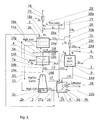
- Fig. 3 shows the connections of the second reactor for the calcination of magnesium carbonate or a mixture of calcium and magnesium carbonates with the waste heat boiler and with the third bio-hydrogen generation reactor and with the power and heat generation unit and with the regenerating CO 2 stream heater
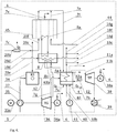
- Fig. 4 depicts the power generation unit combined with a high temperature fuel cell and with a gas-steam power and heat plant
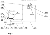
- Fig. 5 shows a solar collector unit connected with the regenerating CO 2 stream.
- the first bio-carbon and fossil carbon hydrogasification reactor 1 shown in Fig. 2 there is carried out a complete conversion of bio-carbon and fossil carbon using bio-hydrogen.
- the system for the production of bio-methane and eco-methane as well as power and thermal energy is depicted in Fig. 1 , and the power generation unit is shown in Fig. 4 .
- the fuel cell unit 45 is used to start-up the system and to generate electricity for captive use.
- the product of biomass pyrolysis is bio-carbon as well as vapours and combustible pyrolytic gas conveyed via a pipeline 22a to a gas burner 22c in the apparatus 22 and through a pipeline 22b to a gas burner 9b located in the preheater 9 of the regenerating CO 2 stream.
- the bio-carbon is conveyed from the apparatus 22 , using a bio-carbon conveyor 23 , to a carbon mixture preparation unit 25 , where it is mixed and appropriately comminuted together with coal fed to the unit 25 through a conveyor 24 .
- This mixture without any special pre-treatment, is fed by a conveyor 26 to the top of the first carbon hydrogasification reactor 1 where it is hydrogasified to bio-methane and eco-methane at approx.
- bio-hydrogen coming from the third bio-hydrogen production reactor 3 said hydrogen being conveyed through a bio-hydrogen pipeline 18a and, after cooling in a heat exchanger 7d connected to a waste heat boiler 4 , fed through a pipeline 18b to the bottom of the first reactor 1 .
- Bio-hydrogen by flowing through a fluidised bed 1f of a mixture of carbon with fine coke in the external chamber 1b of the first reactor 1 , said chamber having a thermal insulation 1d , causes thermal fluidisation of that bed and reacts with bio-carbon and coal to produce a reactive gas that contains about 50% hydrogen and 50% methane, said gas flowing through holes 1h of the shell into the internal chamber 1c and, while flowing co-currently with the falling suspended bed of the carbon mixture it react with that mixture which is fed to the internal chamber using the carbon mixture conveyor 26 from the mixture preparation unit 25 through the mixture inlet 1a to the chamber 1c .
- Vapours and residual gases are removed through pipeline 17 , and the mixture of bio-methane and eco-methane flows through the pipeline 20 and is split into two equal streams - hot bio-methane fed via pipeline 20a to the third bio-hydrogen production reactor and eco-methane fed through pipeline 20b and cooled in the heat exchanger 7c connected via a heat pipeline to the waste heat boiler 4 , then supplied through pipeline 20d to feed the power generation unit 5.
- Surplus eco-methane is supplied through pipeline 20c to a compressor which compresses eco-methane in a compressed eco-methane tank.
- the third bio-hydrogen production reactor 3 comprises tubes filled with a catalyst, i.e. nickel on a ceramic support. Hot bio-methane at a temperature of approx.
- thermal energy especially during the start-up of the third reactor 3 , can be supplied by a hot stream of CO 2 at a temperature of approximately 800°C supplied by a pipeline 10e from the CO 2 stream preheater 9 and flowing around the tubes in the third reactor 3 .
- the bio-hydrogen production reaction takes place at a temperature of about 500°C at appropriately increased pressure. Increasing the pressure to 3MPa results in increased reaction speed, reduces the size of the third reactor 3 and increases the MgCO 3 thermal decomposition temperature, thereby boosting the operation of the CO 2 acceptor, and decreases reaction temperature.
- Heat from the heat exchangers 7c and 7d is supplied through heat pipelines, preferably the collector pipeline 7a , to the waste heat boiler 4, as well as from the hot stream of regenerating CO 2 at a temperature of about 400°C supplied to the heat exchanger in the boiler by a CO 2 pipeline 10b. Most heat is supplied to the boiler by the power generation unit 5 through flue gas pipeline 7g .
- the waste heat boiler 4 is also supplied with make-up water from condensates and from an external source of water using a water pipeline 12 .
- the waste heat boiler 4 produces process steam at about 400°C, which is supplied through a process steam pipeline 11a to the third bio-hydrogen production reactor 3 , and power steam at a temperature of about 585°C supplied via a power steam pipeline 11b to the power steam turbine 38 TP in the power generation unit 5 .
- the spent CO 2 acceptor in the form of magnesium carbonate is supplied from the third bio-hydrogen production reactor 3 using the spent CO 2 conveyor 14 and fed at the top of the second reactor 2 , said reactor being shaft-shaped and intended for the calcination of magnesium carbonate.
- the regenerated CO 2 acceptor in the form of magnesium oxide is fed from the bottom of the second reactor 2 via a feeder 2a and a CO 2 acceptor conveyor 13 back to the third reactor 3 .
- the calcination of magnesium carbonate occurs at a temperature of approx.
- This stream while passing through the fluidised bed of magnesium carbonate, causes its thermal decomposition and the regenerated magnesium oxide drops down along the reactor onto a feeder 2a , and the enriched CO 2 stream, cooled down at the exit of the second reactor 2 to about 400°C, enters the pipeline 10a , and then is split into two streams of CO 2 - the first stream of regenerating CO 2 flows through pipeline 10d to heat exchanger 8 located in the power generation unit 5 where it is heated to about 650°C by fuel cells 45 operating at a temperature of 650°C and by a part of the blowdown exhaust flue gas at approximately 700°C discharged from an extraction gas turbine 36 via a heat exchanger 8b and is fed to the waste heat boiler 4, and then the regenerating CO 2 stream at approx.
- 650°C flows through a CO 2 pipeline to a regenerating CO 2 heat exchanger 9 where it is heated up to approx. 700°C by a gas burner 9b supplied with pyrolytic gas fuel fed to the burner through the pipeline 22b and the regenerating CO 2 stream so heated is supplied through a CO 2 pipeline 10 to the nozzle or nozzle system 2b located at the bottom of the second magnesium carbonate calcination reactor 2 .
- the heat exchanger 7c through which a hot stream of eco-methane flows at a temperature of approximately 800°C gets connected via a heat pipeline to the CO 2 regenerating stream heater 9 and further to the waste heat boiler 4 .
- the second stream of excess CO 2 at a temperature of approximately 400°C flows through the CO 2 pipeline 10b to the heat exchanger 4a in the waste heat boiler heat 4 and, cooled down in the boiler, is discharged by CO 2 pipeline 10f for utilisation.
- the cooled eco-methane stream flows through the pipeline 20d to the power generation unit 5 , said unit having a connection to a power grid 6 , where it feeds the fuel cell 45 and a gas-steam power and heat plant.
- the fuel cell also comprises a heat exchanger 8a connected to a heat exchanger in the collector heat exchanger 8 of the power generation unit 5 . It also has a connection through an inverter to the power network 6 .
- the cooled eco-methane stream also flows through the pipeline 20e into a combustion chamber 34 of a gas turbine unit that consists of a first gas turbine 36 connected via a shaft to a first generator 36a and to an air compressor 35 , said first generator 36a having a connection to the power grid 6 .
- the air compressor 35 delivers air to the combustion chamber 34 through a pipeline 42 .
- the hot and compressed flue gases at a temperature of approx.
- 1200°C leave the chamber 34 and flow to the first gas turbine 36 where they expand and partially cool down to a temperature of approximately 700°C in the last stage of the turbine and the flue gases flow through the blowout flue gas pipeline 43 to the heat exchanger 8b located in the collector heat exchanger 8 and further are sent to the waste heat boiler 4 .
- the expanded flue gases leaving the first turbine 36 are sent through a flue gas pipeline 7g directly to the waste heat boiler 4 .
- the waste heat boiler 4 produces process steam at about 400°C, said steam being sent through steam pipeline 11a to the third reactor 3 , and power steam at 585°C sent through steam pipeline 11b to a second steam turbine 38 coupled through a shaft to a second generator 38a , said generator having a connection to the power grid 6 .
- the steam turbine 38 is connected by a cooled down steam pipeline to a condensing unit 39 , from which the resulting condensate flows through a condensate pipeline 40 to a condensate pump 41 and are pumped to the waste heat boiler 4 .
- Bio-carbon with elemental carbon content C' of 77% was fed using bio-hydrogen to the bio-carbon hydrogasification process.
- a complete gasification of the bio-carbon is carried out.
- the power generation unit is presented in Fig. 4 . It is a fuel cell being a part separated from the system shown in Fig. 4 .
- Dry straw was used as the biomass subjected to the full pyrolysis to bio-carbon process at a temperature of about 300°C , producing about 350 kg of bio-carbon per 1 tonne of dry straw plus pyrolytic gas.
- Dry straw is entered using a biomass conveyor 21 to a biomass pyrolysis apparatus 22 , then the bio-carbon produced is fed to a bio-carbon preparation unit 25 where it is appropriately comminuted, and a part of the pyrolytic gas is fed via a pipeline 22a to a gas burner 22c in the apparatus 22 , and the other part of the pyrolytic gas is fed via a pipeline 22b to a gas burner 9b in the regenerating CO 2 stream preheater 9 .
- bio-carbon is fed via a bio-carbon conveyor 26 at the top of the first bio-carbon hydrogasification reactor 1 where it undergoes complete hydrogasification to bio-methane using bio-hydrogen at a temperature of approx. 815°C according to a method provided in Example I.
- raw gas is fed via a pipeline 16 to a gas and vapour separator 15 .
- the composition of the raw biogas is given in Example I.
- the raw gas is desulphurised and separated, preferably on a membrane through which only hydrogen flows, in a known way, recycled via pipeline 19 to the bio-hydrogen pipeline 18a , whereas the bio-methane stream introduced to the pipeline 20 is split into two equal streams - a hot bio-methane stream supplied through a pipeline 20a to the third bio-hydrogen production reactor 3 , and a stream of bio-methane cooled down in the heat exchanger 7c , supplied through a pipeline 20d to feed the power generation unit 5 in the form of a fuel cell 45.
- Surplus bio-methane is supplied through pipeline 20c to a compressor which compresses bio-methane in a compressed bio-methane tank.
- the production of bio-hydrogen in the third reactor 3 is carried out as shown in Example I.
- the operation of the waste heat boiler 4 producing only process steam at a temperature of approximately 400°C delivered through process steam pipeline 11a to the third bio-hydrogen production reactor 3 , and partly through pipeline 11b for heating purposes, is carried out as described in Example I.
- the calcination of the spent CO 2 acceptor in the form of magnesium carbonate in the second reactor 2 using a hot stream of regenerating CO 2 supplied through CO 2 pipeline 10d to the heat exchanger 8 located in the fuel cell 45 , where it is heated up to a temperature of about 600°C, and then fed to the heater 9 that heats this stream, where it is heated up by the gas burner 9b supplied with pyrolytic gas and partly with bio-methane to approximately 700°C, and then recycled via CO 2 pipeline 10 to the second MgCO 3 calcination reactor 2 , is carried out as described in Example I.
- the bio-methane stream flows to the power generation unit 5 where it feeds the fuel cell 45 .
- Hot flue gases from the fuel cell flow through pipelines 7e and further through collector pipeline 7f to the waste heat boiler 4 where they pass heat, and then are discharged to the atmosphere.
- the fuel cell also comprises a heat exchanger 8a , shown in Fig. 1 as the heat exchanger 8 in the power generation unit 5 , connected to the preheater 9 of the regenerating CO 2 stream and further to the second MgCO 3 calcination reactor. It also has a connection through an inverter to the power grid 6 .
- Fig. 4 the power generation unit is shown in Fig. 4 . It is a gas-steam heat and power plant that is part of the power generation unit 5 . Dry wood chips were used as the biomass for the partial pyrolysis process carried out in a biomass pyrolysis apparatus 22 at about 170°C - 270°C, fed into the apparatus 22 using a biomass conveyor 21 .
- the product of the incomplete pyrolysis of biomass is semi-carbon as well as vapours and combustible pyrolytic gas, a part of which gas is supplied via a pipeline 22a to a gas burner 22c in the biomass pyrolysis apparatus 22 and the other part is supplied through a pipeline 22b to a gas burner 9b located in the preheater 9 of the regenerating CO 2 stream.
- the semi-carbon is conveyed from the biomass pyrolysis apparatus 22 , using a bio-carbon conveyor 23 , to a carbon mixture preparation unit 25 , where it is mixed and appropriately cominuted together with lignite fed to the unit 25 through a coal conveyor 24 .
- the carbon mixture formed is conveyed by conveyor 26 to an internal chamber 1c of the first reactor 1 .
- Production of bio-hydrogen occurs in the third reactor 3 as a result of a reaction of bio-methane with water vapour and a CO 2 acceptor which is a mixture of magnesium oxide and calcium oxide in the ratio of 1 : 3.
- the energy needed for the endothermic reaction is brought about by hot bio-methane supplied to the third reactor 3 by pipeline 20a , hot steam supplied by steam pipeline 11a , and CO 2 -uptake reactions of the CO 2 acceptor supplied to the third reactor 3 by CO 2 acceptor conveyor 13 , whereas the amount of thermal energy supplied can be controlled, inter alia, by the selection of the CaO content in the mixture of magnesium oxide and calcium oxide.
- the reaction of bio-hydrogen production occurs at about 500°C in the presence of a ceramic-supported nickel catalyst inside tubes 3a , which can be heated by a hot stream of CO 2 at a temperature of 750°C, flowing around these tubes especially in the start-up phase of the third reactor 3 .
- the produced and cooled down bio-hydrogen is sent to the first carbon and bio-carbon hydrogasification reactor 1 .
- the reaction of bio-hydrogen with elemental carbon C' from the semi-carbon and with elemental carbon C from the lignite produces bio-methane and eco-methane and heat related to the carbon hydrogasification reaction.
- a part of that heat, from the cooling down of eco-methane in heat exchanger 7c is supplied by a heat pipeline to the waste heat boiler 4 .
- the waste heat boiler is supplied with heat from many sources: the power generation unit 5 , flue gases from gas turbine via flue gas pipeline 7g , from cooling of bio-hydrogen in heat exchanger 7d , and from the CO 2 stream leaving the second spent CO 2 acceptor calcination reactor 2 via pipeline 10b to the heat exchanger 4a in the waste heat boiler 4 and leaving the waste heat boiler 4 via CO 2 pipeline 10c to a CO 2 sequestration facility.
- the waste heat boiler 4 which receives water from the condenser 39 from an external water source 12 , produces process steam which is supplied by steam pipeline 11a to the third reactor 3 and power steam supplied by pipeline 11b to the second steam turbine 38 in the power generation unit 5 .
- a descending bed of carbonates CaCO 3 and MgCO 3 fluidised by a hot stream of regenerating CO 2 at a temperature of about 950°C undergoes thermal decomposition, with magnesium carbonate being decomposed in the upper part of this bed at about 630°C, and calcium carbonate decomposed in the lower part of this layer at a temperature of approximately 950°C.
- Regenerated CO 2 acceptor in the form of a mixture of magnesium and calcium oxides is supplied by CO 2 acceptor conveyor 13 to the third reactor 3 , and carbon dioxide leaving the second reactor 2 through the CO 2 pipeline 10a at a temperature of approximately 400°C is split into two streams: the first one is fed via CO 2 pipeline 10b to the heat exchanger 4a in the waste heat boiler 4 and so cooled flows through CO 2 pipeline 10c to a CO 2 sequestration process, especially based on silicates, e.g. serpentine silicate. Products of such fixation, magnesium carbonate, silica and water, are durable and easy to store.
- the second stream of CO 2 is sent by CO 2 pipeline 10d to heat exchanger 8 in the power generation unit 5 where it is heated up by a part of the exhaust gas at a temperature of approximately 700°C that leaves the first gas turbine 36 to approximately 650°C, then the stream is directed to the preheater 9 where it is heated up to a temperature of about 1100°C by a gas burner 9b operating on pyrolytic gas or by any other gaseous fuel, by pulverised fuel burner 27a operating on pulverised coke, and then that stream is sent via CO 2 pipeline 10 to a nozzle system 2b located at the bottom of the second reactor 2 .
- Cooled down eco-methane is sent via pipeline 20d to the power generation unit 5 being a gas-steam power and heat plant to combustion chamber 34 of the first gas turbine 36 in that unit.
- the process of generating electricity and heat has been shown in Example I.
- the preheater 9 of the regenerating CO 2 stream is connected to a solar collector system as shown in Fig. 5 .
- the CO 2 stream as a heat carrier, is sent from heat exchanger 30 via pipeline 31 to a spiral heat exchanger 33b located in the focus 33a of a concave mirror and is recycled by a heat carrier recycle pipeline to the preheater 9 .
- CO 2 stream as the heat carrier is heated up to approx. 1200°C and recycled back to a heat exchanger 30 located in the preheater 9 from which heat is supplied through CO 2 pipeline 10 to the second spent CO 2 acceptor calcination reactor 2 .
- thermochemical energy is accumulated in calcium oxide and in the manufactured gas fuel, which substances can be stored, and their storage method depends on the annual sunshine time.
- the system consists of a first carbon and/or bio-carbon hydrogasification reactor 1 , a second carbonate calcination reactor 2 , and a third reactor 3 for the production of bio-hydrogen, a waste heat boiler 4 , a power generation unit 5 connected to a power grid 6 , heat transfer pipelines 7a and 7b , a collector heat exchanger 8 in the power generation unit, a preheater 9 for the regenerating CO 2 stream, CO 2 gas pipelines 10 (a, b, c, d, e, f), steam pipelines 11a and 11b , a water pipeline 12 , a conveyor 13 for CO 2 acceptor, a conveyor 14 for calcium and/or magnesium carbonates, a gas and steam separator 15 , a raw gas pipeline 16 , a pipeline 17 for dusts and residual gases, bio-hydrogen pipelines 18a and 18b , a hydrogen pipeline 19 , a bio-methane pipeline 20a and eco-methane pipelines 20b
- the first carbon and bio-carbon hydrogasification reactor 1 is connected at the top by the carbon mixture conveyor 26 to the carbon mixture preparation unit 25 which has two connections: a connection to the lignite or coal conveyor 24 and a connection to the bio-carbon conveyor 23 , said bio-carbon conveyor 23 being connected to the biomass hydrolysis apparatus 22 .
- This apparatus has an inlet for dry biomass connected to the biomass conveyor 21 ; it also has an outlet for bio-carbon connected to the bio-carbon conveyor 23 , as well as an outlet for combustible pyrolytic gases connected via pipeline 22a to a gas burner in the biomass pyrolysis apparatus 22 and via pipeline 22b to a gas burner in the regenerating CO 2 stream preheater 9 .
- the first reactor 1 has at its bottom a bio-hydrogen inlet connected via the bio-hydrogen pipeline 18b and further through the heat exchanger 7d and hot bio-hydrogen pipeline 18a to the third bio-hydrogen production reactor 3 , whereas pipeline 18a is connected through bio-hydrogen recycle pipeline 19 to vapour and gas separator 15 .
- the first reactor 1 also has at its bottom an outlet for fine coke, connected using the fine coke conveyor 28 to the ground fine coke conveyor 28a and, via a coal pulveriser mill, to the pulverised fuel burner in the regenerating CO 2 stream preheater 9 , whereas the coal pulveriser mill is also connected to the fossil carbon and bio-carbon conveyor 27 as well as, by fine coke conveyor 28b , the fine coke outlet is connected to the fine coke storage facility, and, in case of full conversion of fine coke with bio-hydrogen, that outlet becomes the ash outlet connected via conveyor 28b to an ash storage facility.
- the first reactor 1 also has a connection through the raw gas pipeline 16 to the vapour and gas separator 15 , which has at its top a discharge 17 for dust, vapours and residual gases that have been removed from the raw gas.
- the vapour and gas separator 15 has at its bottom a hydrogen outlet connected through the hydrogen recycle pipeline 19 to the bio-hydrogen pipeline 18a , and it also has at its bottom an outlet connected to the methane mixture pipeline 20 which splits into hot bio-methane pipeline 20a connected to the third bio-hydrogen reactor 3 and the hot eco-methane pipeline 20b connected to a heat exchanger and, further, to the power generation unit 5 .
- the eco-methane pipeline 20d also has a branch 20c to receive methane.
- the waste heat boiler 4 has a process steam discharge connected via steam pipeline 11a to the third bio-hydrogen production reactor 3 , as well as a power steam discharge connected via pipeline 11b to a steam turbine in the power generation unit 5 .
- the third bio-hydrogen production reactor 3 also has an inlet for the CO 2 acceptor, connected via CO 2 acceptor conveyor 13 to an outlet for the regenerated CO 2 acceptor at the bottom of the second spent CO 2 acceptor calcination reactor 2 , and also the third reactor 3 has an outlet for spent CO 2 acceptor connected via spent acceptor conveyor 14 to a spent acceptor inlet at the top of the second spent acceptor calcination reactor 2 .
- the inlet of the second reactor 2 there is a CO 2 pipeline 10 connected to heat exchanger 9a located in the regenerating CO 2 stream preheater 9 .
- the outlet for the CO 2 stream from the second reactor 2 is connected to the CO 2 pipeline 10a branching out into pipeline 10b connected to a heat exchanger in the waste heat boiler 4 and further CO 2 outlet.
- the waste heat boiler 4 has a connection via CO 2 pipeline 10c to a CO2 sequestration subsystem and, via pipeline 10f , to CO 2 processing equipment.
- CO 2 pipeline 10d is connected to pipeline 10a and through the collector heat exchanger 8 located in the power generation unit 5 to heat exchanger 9a in the regenerating CO 2 stream preheater 9 equipped with a gas burner connected via pyrolytic gas pipeline 22b to pyrolytic gas pipeline 22a , as well as equipped with a pulverised coal burner connected through a carbon pulveriser mill to the fine coke conveyor 28a or the carbon/bio-carbon conveyor 27 , and also equipped with heat exchanger 30 connected to a solar collector or a collector unit.
- the power generation unit 5 has an electric connection 6 to a power grid, and a connection, via heat pipeline 7b to a municipal heat pipeline, as well as a connection via hot flue gas pipeline 7g to the waste heat boiler 4 ; additionally, the waste heat boiler 4 has a connection via water pipeline 12 to an external source of water.
- Fig. 2 shows a schematic diagram of a sub-system for the production of bio-methane and eco-methane with the use of the first low pressure carbon hydro gasification reactor 1 , vapour and gas separator 15 , carbon feed preparation unit 25 , biomass pyrolysis apparatus 22 , heat exchanger 7d , as well as conveyors and pipelines.
- the first carbon and bio-carbon hydrogasification reactor 1 has a thermal shell 1d, internal reaction chamber 1c comprising a suspended falling carbon bed, said chamber connected through carbon feed inlet 1a to carbon feed conveyor 26 .
- the chamber 1c has at its top an inlet 1h for the reactive gas, and at the bottom a connection to an external chamber 1b comprising a fluidised bed 1f of the carbon feed with fine coke.
- Raw gas outlet is connected via a pipeline 16 to the vapour and gas separator 15 .
- chamber 1c has a bio-hydrogen inlet 1g connected via cooled down bio-hydrogen pipeline 18b to heat exchanger 7d and further by hot bio-hydrogen pipeline 18a to the third bio-hydrogen production reactor 3 , and it also has a fine coke outlet 1e connected to fine coke conveyor 28 which is connected to ground fine coke conveyor 28a and the conveyor 28b that sends the fine coke to storage, and, in case of full conversion of the carbon feed with bio-hydrogen, this will be ash outlet 1e connected to conveyor 28b sending the ash to storage.
- the heat exchanger 7d is connected via a heat pipeline to the waste heat boiler, and bio-hydrogen pipeline 18a is connected by the hydrogen recycle pipeline 19 to the hydrogen outlet at the vapour and gas separator 15 .
- This separator also has an outlet for the bio-methane and eco-methane mixture connected to the mixture pipeline 20 and a discharge for dust, vapours and residual gases connected to pipeline 17 .
- the first carbon and bio-carbon hydrogasification reactor 1 is connected at the top by carbon mixture feed conveyor 26 to the carbon feed preparation unit 25 which is connected to coal conveyor 24 and, by bio-carbon conveyor 23 , to the biomass pyrolysis apparatus 22 .
- the apparatus 22 has a connection to dry biomass conveyor 21 and is connected by the pyrolytic gas pipeline 22a to the gas burner 22c located in that apparatus and a connection of that pipeline by pipeline 22b to the gas burner located in the regenerating CO 2 stream preheater.
- Fig. 3 depicts a schematic drawing of ties between the second reactor 2 for the calcination of magnesium carbonate or a mixture of magnesium and calcium carbonates with the waste heat boiler 4 and the third reactor 3 for the production of bio-hydrogen as well as the power generation unit 5 and the regenerating CO 2 stream preheater 9 .
- the second reactor 2 for the calcination of magnesium carbonate or a mixture of magnesium and calcium carbonates is preferably built in the shape of a shaft furnace; it consists of a thermally insulated shell having at its top an inlet for spent CO 2 acceptor, connected via spent CO 2 acceptor conveyor 14 to the spent acceptor outlet at the third bio-hydrogen production reactor 3 , and having at the bottom an outlet for regenerated CO 2 acceptor in the form of magnesium oxide or a mixture of magnesium and calcium oxides, said outlet connected to a CO 2 acceptor feeder 2a and further, via acceptor conveyor 13 , to the CO 2 acceptor inlet at the third reactor 3 .
- the second reactor 2 has at its bottom a CO 2 nozzle system 2b that feeds hot regenerating CO 2 stream at a temperature of approx. 650°C - 700°C in case of thermal decomposition of MgCO 3 in the fluidised bed or approx.
- the regenerating CO 2 stream preheater 9 additionally has a gas burner 9b connected to pyrolytic gas pipeline 22b , a pulverised coal burner 27a with a fine coke/coal pulveriser mill connected to ground fine coke conveyor 28a and to coal/bio-coal conveyor 27 , whereas the ground coke conveyor 28a has a connection to the fine coke conveyor 28 which also has a connection to fine coke conveyor 28b discharging to a storage facility.
- the CO 2 preheater 9 also has an outlet for ash, connected to waste conveyor 29 , and also has a heat exchanger 30 connected to the solar collector unit.
- the waste heat boiler 4 has a collective heat inlet 7a connected to a heat exchanger 7d for bio-hydrogen and a heat exchanger 7c for eco-methane. It also has an inlet for condensate and make-up water, connected to water pipeline 12 , and an outlet for power steam connected via steam pipeline 11b to a steam turbine in the power generation unit 5 , and a process steam outlet connected via steam pipeline 11a to the third reactor 3 .
- the hot CO 2 stream pipeline 10 has a connection in the form of CO 2 pipeline 10e to the third reactor 3 .
- the third bio-hydrogen production reactor 3 is built inside with tubes 3a with catalyst inside them, has a bio-hydrogen outlet connected through hot bio-hydrogen pipeline 18a to heat exchanger 7d and to pipeline 19 for recycled hydrogen from the vapour-gas separator.
- the heat exchanger 7d is connected via a pipeline to the waste heat boiler 4 , and also, via cooled down bio-hydrogen pipeline 18b , to the first carbon hydrogasification reactor.
- the hot bio-methane inlet at the third reactor 3 is connected through bio-methane pipeline 20a to methane mixture pipeline 20 coming from the vapour-gas separator 15 , which is also connected to eco-methane pipeline 20b connected to heat exchanger 7c and further connected through pipeline 20c and pipeline 20d to the power generation unit 5 . That unit also has a connection 6 to a power grid.
- Fig. 4 depicts a power generation unit 5 that consists of a high-temperature fuel cell 45 and a gas-steam power and heat plant which basically consists of a first gas turbine 36 coupled via shaft with a first generator 36a , a second steam turbine 38 connected via shaft with a second generator 38a , and a waste heat boiler 4 .
- Hot eco-methane pipeline 20b connected through heat exchanger 7c to cooled down eco-methane pipeline 20d which branches out into three branches: the first branch in the form of eco-methane pipeline 20e is connected to the combustion chamber 34 of the gas turbine unit, the second branch on the form of eco-methane pipeline 20f is connected to the fuel cell 45 , and the third branch 20c .
- Heat exchanger 7c is connected by a heat pipeline to the waste heat boiler 4 .
- the fuel cell 45 is connected to an air pipeline 44 , and the pipelines 7e for flue gases exiting the fuel cell 45 are connected through collector pipeline 7f to a heat exchanger in the waste heat boiler 4.
- the heat exchanger 8a located in the fuel cell 45 is connected to the collector heat exchanger 8 through pipeline 10d with regenerating CO 2 stream preheater.
- the electricity outlet at the fuel cell 45 is connected by an inverter to a power grid 6 .
- the combustion chamber 34 is connected at the inlet, by air pipeline 37, to an air compressor 35 coupled via shaft with the first gas turbine 36 and a start-up engine 35a, and at its exit the combustion chamber 34 is connected by hot flue gas pipeline 42 to the first gas turbine 36 coupled via shaft with the first generator 36a connected to the power grid 6 , whereas the exit of the discharge flue gases from the turbine is connected by flue gas pipeline 43 to the heat exchanger 8b located in the collector heat exchanger 8 of the power generation unit 5 and further connected to the waste heat boiler 4 , and the outlet of the expanded flue gas from the first turbine 36 is connected via flue gas pipeline 7g to the waste heat boiler 4 which has a discharge outlet 43a for cooled down flue gas and an inlet of the collector heat pipeline 7a.
- the waste heat boiler 4 has a hot CO 2 stream inlet through CO 2 pipeline 10b and an outlet of that pipeline branching out into CO 2 pipeline 10c connected to the CO 2 sequestration sub-system and CO 2 pipeline 10f connected to CO 2 pipeline 10g.
- the waste heat boiler 4 also has a process steam outlet connected via steam pipeline 11a to the third bio-hydrogen production reactor, as well as a power steam discharge outlet connected through steam pipeline 11b to the second steam turbine 38 , and the outlet at the second turbine 38 is connected to a condenser 39 which, in turn, via condensate pipeline 40 through condensate pump 41 , is connected to the waste heat boiler 4 .
- the waste heat boiler 4 also has a connection to an external water source through water pipeline 12 .
- Fig. 5 shows a solar collector unit coupled with the regenerating CO 2 stream preheater.
- the regenerating CO 2 stream preheater 9 is equipped with an incoming CO 2 stream pipeline 10d connected to the heat exchanger 9a and further through the regenerating CO 2 stream pipeline 10 connected to the second spent CO 2 acceptor calcination reactor. It is also equipped with a gas burner 9b connected to the pyrolytic gas pipeline 22b and a pulverised coal burner 27a with a pulveriser mill connected to the ground fine coke conveyor 28a and/or the coal/bio-carbon conveyor 27 .
- the preheater 9 is equipped with a heat exchanger 30 which at the outlet is connected via heat carrier pipeline 31 to the heat exchanger 33b located in the focus 33a of concave mirrors in the solar collector unit 33 and further through heat carrier pipeline 32 it is connected to the heat exchanger 30 located inside the preheater 9 .
Landscapes
- Chemical & Material Sciences (AREA)
- Engineering & Computer Science (AREA)
- Organic Chemistry (AREA)
- Combustion & Propulsion (AREA)
- Oil, Petroleum & Natural Gas (AREA)
- Chemical Kinetics & Catalysis (AREA)
- Mechanical Engineering (AREA)
- General Engineering & Computer Science (AREA)
- General Chemical & Material Sciences (AREA)
- Inorganic Chemistry (AREA)
- General Health & Medical Sciences (AREA)
- Health & Medical Sciences (AREA)
- Physics & Mathematics (AREA)
- Thermal Sciences (AREA)
- Hydrogen, Water And Hydrids (AREA)
- Processing Of Solid Wastes (AREA)
- Organic Low-Molecular-Weight Compounds And Preparation Thereof (AREA)
Claims (23)
- Die Methode zur Herstellung von Biomethan und Ökomethan sowie Strom und Wärme unter Verwendung des Verfahrens der Pyrolyse der Biomasse zu Biokohle, die gegebenenfalls mit entsprechend zerkleinerter und aufbereiteter Steinkohle vermischt wird und unter Verwendung des Verfahrens der Hydrovergasung des Kohlegemisches zu Rohgas und dessen Entschwefelung und Trennung in Wasserstoff und Methan, unter Verwendung des Verfahrens der Wasserstofferzeugung bei der Reaktion von Methan mit Wasserdampf und CO2-Akzeptor und der Akzeptorregeneration und unter Verwendung einer Brennstoffzellenanlage vom Typ MCFC und eines Gas- und Dampf-Heizkraftwerks zur Erzeugung von Strom und Wärme, gekennzeichnet dadurch, dass das zerkleinerte trockene Pflanzenmaterial oder Abfallmaterial entweder einzeln oder in bestimmten Mengen dem Pyrolyseprozess unterworfen wird, entweder im Temperaturbereich von 170 °C bis 270 °C unter Normaldruck zu Halbkohlenstoff und Pyrolysegas, oder im Temperaturbereich von 270 °C bis 300 °C zu Biokohlenstoff und Pyrolysegas oder im Temperaturbereich über 300 °C, wobei ein Teil des Pyrolysegases zur Durchführung der Biomassepyrolyse in der Biomassepyrolysevorrichtung geleitet wird und der zweite Teil des Pyrolysegases zur Erwärmung des CO2-Regenerationsstroms im Erhitzer geleitet wird, während der erhaltene Halbkohlenstoff mit einem Gehalt an elementarem Kohlenstoff von etwa 60% - 65% günstig mit zerkleinerter Braunkohle vermischt wird, während der Biokohlenstoff mit einem Gehalt an elementarem Kohlenstoff von etwa 65% - 80% mit zerkleinerter Steinkohle im Verhältnis des elementarem Kohlenstoffs C' aus Biokohlenstoff zu elementarem Kohlenstoff C aus fossilem Kohlenstoff günstig von C' : C = 1 : 1 vermischt wird und das Gemisch in den ersten Nieder- oder Hochdruck Kohlevergasungsreaktor eingebracht wird, in dem entweder der vollständige Hydrobehandlungsprozess mittels Biowasserstoff zu Rohgas und Asche oder der unvollständige Hydrobehandlungsprozess von Kohle und Biokohle zu Rohgas und Koksgrus durchgeführt wird, wobei der Koksgrus teilweise zur Koksgrusdeponie geführt wird und teilweise zur Erwärmung des CO2-Regenerationsstroms im Erhitzer geleitet und dort verbrannt wird, während das entstehende Rohgas dem Prozess der Trennung von Dämpfen und Gasen zugeführt wird, wo es getrocknet, entschwefelt und anschließend in Wasserstoff, Restgase und ein Methangemisch aus reinem Biomethan und Ökomethan getrennt wird, wobei ein Teil des Methans nach dem Abkühlen in einem Wärmetauscher der Energieerzeugungseinheit zugeführt wird, von der aus die Wärme in den Wärmetauscher zur Erwärmung des CO2-Regenerationsstroms und in den Wärmetauscher in einem Rückgewinnungskessel zur Erzeugung von Prozess- und Energiedampf zugeführt wird und der zweite Teil des gekühlten Methans entweder dem Kompressor oder dem Kondensator oder dem Gasnetz zugeführt wird, während das heiße Biomethan mit einer Temperatur von etwa 800 °C in den dritten Reaktor zur Erzeugung von Bio-Wasserstoff eingespeist wird, in dem bei der Reaktion von Biomethan mit heißem Dampf, der aus dem Rückgewinnungskessel zugeführt wird und dem CO2-Akzeptor der Bio-Wasserstoff erzeugt wird und nach dem Abkühlen dem Prozess der Hydrovergasung des Kohlegemisches im ersten Reaktor zugeführt wird, während der verbrauchte CO2-Akzeptor in Form einer Mischung aus Magnesium- und Calciumcarbonaten dem zweiten Reaktor zum Kalzinierungsprozess mittels eines heißen CO2-Regenerationsstroms zugeführt wird, dann wird der regenerierte CO2-Akzeptor in Form von Magnesiumoxid und Calciumoxid in den dritten Reaktor eingebracht und ein CO2-Strom mit einer Temperatur von etwa 400 °C, der den zweiten Rektor verlässt, wird im ersten Teil in den dritten Reaktor zum Wärmetauscher im Rückgewinnungskessel zugeführt, wo es gekühlt und entweder zu einem bekannten Prozess der CO2-Sequestrierung oder zur Verdichtung und Verfestigung von CO2 zu Trockeneis oder zur Atmosphäre geleitet wird, und im zweiten Teil als regenerativer CO2-Strom auf die für die Kalzinierung von Magnesiumcarbonat erforderliche Temperatur von etwa 700 °C erhitzt wird, oder auf die Temperatur von etwa 1000 °C - 1100 °C, die für die Kalzinierung eines Gemisches aus Magnesium- und Calciumcarbonaten und auch in einem Erhitzer benötigt wird, der periodisch durch einen in einem Solarkollektor auf die Temperatur von 1100 °C - 1200 °C erwärmten Wärmeträger versorgt wird; der so erwärmter regenerativer CO2-Strom wird in den zweiten Reaktor eingeleitet.
- Die Methode nach dem Anspruch 1 gekennzeichnet dadurch, dass das zerkleinerte trockene Kohlenstoffgemisch aus Halbkohlenstoff mit Braunkohle oder Biokohlenstoff mit Steinkohle nach der Luftverdrängung durch CO2 von der Vorrichtung zur Herstellung des Kohlenstoffgemisches zum ersten Niederdruckreaktor geleitet wird, wobei der Prozess der Hydrovergasung des Kohlegemisches zunächst in der Innenkammer in einem suspendierten Bett stattfindet, das gleichzeitig mit dem von oben in die Innenkammer eingeleiteten Gas, das etwa 50% H2 und 50% CH4 enthält, bei einer Temperatur von etwa 815 °C unter Normaldruck fällt, und das dabei erhaltene Rohgas vom ersten Reaktor zum Dampf- und Gasabscheider geleitet wird, wo es von Staub und Zusatzgasen gereinigt wird, und insbesondere entschwefelt wird, wonach es in ein reines Methangemisch aus Biomethan und Ökomethan und in Wasserstoff getrennt wird, der in den Bio-Wasserstoffstrom zurückgeführt wird, und ein teilweise reagiertes Kohlenstoffgemisch in eine externe Kammer im ersten Reaktor geleitet wird, wo es einer vollständigen Reaktion mit Wasserstoff zu Asche und zu Wasserstoff-Methangas oder einer unvollständigen Reaktion zu Koksgrus und zu Wasserstoff-Methangas unterworfen wird, wobei die Asche auf eine Deponie gebracht wird und der Koksgrus entweder zur Verbrennung oder zur Lagerung gebracht wird, während das Wasserstoff-Methangas von oben in die Innenkammer des Reaktors geleitet wird.
- Die Methode nach dem Anspruch 1 gekennzeichnet dadurch, dass im ersten Hochdruckreaktor das Kohlegemisch in Verbindung mit Mineralöl in Form einer Suspension mittels einer Düse bei einem Druck von etwa 6,8 MPa in den obersten Abschnitt des Reaktors, den so genannten Verdampfungsabschnitt, eingebracht wird und hier bei einer Temperatur von ca. 315 °C wird das Öl verdampft und seine Dämpfe zusammen mit dem heißen Rohgas, das den Mittelabschnitt verlässt, die so genannte I Stufe der Kohlevergasung, zum Dampf- und Gasabscheider geleitet werden, wovon das abgetrennte und anschließend im Kondensator verflüssigte Mineralöl zur Vorrichtung zur Herstellung der Kohlesuspension im Öl zurückgeführt wird, und das gereinigte Rohgas, insbesondere nach der Entschwefelung, in ein Methangemisch und reinen Wasserstoff, der mit Bio-Wasserstoff kombiniert wird, getrennt wird, während die trockenen Kohlenstoff- und Biokohlenstoffteilchen bei einer Temperatur von etwa 300 °C dem Mittelabschnitt zugeführt und in einem Strom von biowasserstoffhaltigem Gas fluidisiert werden, das den unteren Abschnitt des Reaktors verlässt, der als II Stufe der Kohlevergasung bezeichnet wird und im Mittelabschnitt bei erhöhten Temperaturen bis zu etwa 650 °C und bei einem Druck von 6.0 MPa wird die Entgasung und Teilhydratisierung von Kohlepartikeln durchgeführt und dann wird das teilweise reagierte Kohlegemisch im Wirbelbett im unteren Abschnitt des Reaktors bei 750 °C - 950 °C durch den in diesen Abschnitt eingebrachten Biowasserstoff vollständig hydratisiert.
- Die Methode nach dem Anspruch 1 und 2 und 3 gekennzeichnet dadurch, dass als CO2-Akzeptor für den Bio-Wasserstoff-Produktionsprozess das Magnesiumoxid oder ein günstiges Gemisch aus Magnesiumoxid und Calciumoxid in einem günstigen Verhältnis von MgO : CaO = 1 : 3 molarer Mengen von Substanz eingesetzt wird, die für die Zuführung der Wärmemenge in die Bio-Wasserstoff-Produktionsreaktion von ca. 155 kJ/mol - 165 kJ/mol CH4 bei einer Temperatur von über 100 °C während der kontinuierlichen Betriebs des dritten Reaktors erforderlich ist, jedoch in Abhängigkeit von der durch diese Reagenzien in den Reaktor eingebrachten Wärmemenge, wodurch dieses Verhältnis im Bereich von 1 : 10 bis 10 : 1 variiert.
- Die Methode nach dem Anspruch 1 und 2 und 3 gekennzeichnet dadurch, dass bei der thermischen Zersetzung von Carbonaten unter Beteiligung von Sonnenenergie das Calciumoxid der CO2-Akzeptor ist, der die Energie zur Reaktion der Bio-Wasserstoffproduktion liefert.
- Die Methode nach dem Anspruch 4 gekennzeichnet dadurch, dass im zweiten Schachtreaktor im Bett von Magnesium und Calciumcarbonaten, das durch einen heißen CO2-Strom bei einer Temperatur von etwa 1100 °C in der unteren Zone des Reaktors fluidisiert wird, eine thermische Zersetzung von Calciumcarbonat im Temperaturbereich von etwa 1000 °C - 800 °C und in der oberen Zone des Reaktors eine thermische Zersetzung von Magnesiumcarbonat im Temperaturbereich von etwa 800 °C - 400 °C erfolgt, wobei Magnesium- und Calciumoxide und Kohlenstoffdioxid erzeugt werden.
- Die Methode nach dem Anspruch 1 gekennzeichnet dadurch, dass in der Stromerzeugungseinheit Ökomethan zum Betreiben der Gasturbine und der Brennstoffzelle verwendet wird und die Wärme von der Brennstoffzelle mit einer Temperatur von 650 °C zum Wärmetauscher zum Erwärmen des CO2-Regenerationsstroms geleitet wird und die Abgase von der Brennstoffzelle mit einer Temperatur von 400 °C zum Wärmetauscher im Rückgewinnungskessel geleitet werden.
- Die Methode nach dem Anspruch 1 gekennzeichnet dadurch, dass die Abgase des letzten Abschnitt der Gasturbine mit einer vorteilhaften Temperatur von ca. 700 °C dem Wärmetauscher zugeführt werden, um den CO2-Regenerationsstroms zu erwärmen, und die Abgase mit einer Temperatur von 400 °C - 600 °C dem Wärmetauscher im Rückgewinnungskessel zugeführt werden, von dem aus der Energiedampf mit einer Temperatur von ca. 585 °C zur Dampfturbine des Dampfturbosatzes geleitet wird.
- Die Methode nach dem Anspruch 1 gekennzeichnet dadurch, dass die Wärme von Abgasen mit einer Temperatur von etwa 400 °C - 600 °C aus dem Stromerzeugungsblock, die Wärme aus dem CO2-Strom, der den zweiten Kalzinierungsreaktor für Magnesium- und/oder Calciumcarbonaten mit einer Temperatur von etwa 400 °C verlässt, die Wärme aus dem heißen Wasserstoff-Strom mit einer Temperatur von etwa 500 °C und aus dem heißen Strom von Ökomethan, das im ersten Kohlevergasungsreaktor in einer Temperatur von etwa 800 °C erzeugt wird, in den Rückgewinnungskessel geleitet wird.
- Die Methode nach dem Anspruch 8 gekennzeichnet dadurch, dass die Wärme von einem Wärmeträger, der durch Solarenergie auf eine Temperatur von etwa 1100°C - 1200°C erwärmt wird, zum Erhitzer des CO2-Regenerationsstroms geleitet wird.
- Die Methode nach dem Anspruch 10 gekennzeichnet dadurch, dass der durch Sonnenenergie erwärmte Wärmeträger ein Gas ist, das mit Materialien des Solarkonzentratorsatzes nicht reagiert, vorzugsweise Kohlenstoffdioxid oder Stickstoff oder Argon, oder ein Gas mit hoher spezifischer Wärme, vorzugsweise Helium oder mit diesen Materialien nicht reaktiver Dampf, vorzugsweise Wasserdampf oder Flüssigkeit mit hohem Siedepunkt.
- Die Methode nach dem Anspruch 1 gekennzeichnet dadurch, dass die Reagenzien - Biomethan, Wasserdampf und CO2-Akzeptor, aus denen der Bio-Wasserstoff in Anwesenheit von Nickelkatalysator Ni/Al2O3 in einem Temperaturbereich von 500 °C - 900 °C und bei einem Druck von 1,5 MPa - 4,5 MPa im ersten Abschnitt des dritten Reaktors in den Reaktorrohren erzeugt wird, durch einen heißen CO2 -Strom mit einer Temperatur von etwa 800 °C - 1000 °C - insbesondere während der Inbetriebnahme des dritten Reaktors - erwärmt werden.
- Die Methode nach dem Anspruch 1 und 12 gekennzeichnet dadurch, dass im dritten Reaktor für die Reaktion zur Erzeugung des Biowasserstoffs aus Kohlenmonoxid und dem Wasserdampf mit Gasgemisch, das vom ersten Abschnitt des dritten Reaktors zum zweiten Abschnitt dieses Reaktors strömt, der im niedrigeren Temperaturbereich als der erste Abschnitt arbeitet, ein Katalysator oder Cu-Zn/Al2O3 im Temperaturbereich von 200 °C bis 300 °C oder bei höheren Temperaturen von 350 °C bis 500 °C ein Fe/Al2O3-Katalysator und dann bei Temperaturen von 200 °C bis 300 °C ein Cu/Al2O3-Katalysator verwendet wird.
- Das System zur Herstellung von Biomethan und Ökomethan sowie Strom und Wärme, bestehend aus einem Kohlevergasungsreaktor, einem Kalzinierungsreaktor für Magnesium- und Calciumcarbonate, einem Reaktor zur Erzeugung von Bio-Wasserstoff, einem Dampf- und Gasverteiler, einer Biomasse-Pyrolyseeinheit, einer Aufbereitungsanlage des Kohlegemisches, einem Rückgewinnungskessel, der gegebenenfalls mit einem CO2-Sequestrierungssubsystem kombiniert ist, einer Stromerzeugungseinheit, einem Erhitzer des CO2-Regenerationsstroms, Wärmetauschern, Förderern, Pumpen sowie Rohrleitungen für Flüssigkeiten, Dämpfe und Gase, gekennzeichnet dadurch, dass der erste Kohlevergasungsreaktor (1) einen Eingang aufweist, der durch den Förderer (26) des Kohlegemisches oder der Suspension mit der Vorbereitungsvorrichtung (25) des Kohlegemisches oder der Suspension verbunden ist, die mit der Biomassepyrolysevorrichtung (22) und dem Stein- oder Braunkohleförderer (24) verbunden ist, und dass der erste Reaktor (1) über einen Ausgang (28) für Koksgrus oder Asche sowie einen Ausgang (16) für Rohgas des Reaktors (1) verfügt und eine Verbindung mit dem Dampf- oder Gasverteiler (15) aufweist, der eine Mündung (17) für Staub, Restdämpfe und - gase und die Wasserstoffabgabe in Form einer Rohrleitung (19) hat, die mit der Bio-Wasserstoffabgabe des dritten Reaktors (3) in Form einer Rohrleitung (18a) und (18b) mit dem ersten Reaktor (1) verbunden ist, wobei der Dampf- und Gastverteiler (15) auch einen Ausgang in Form einer Rohrleitung (20) für Biomethan und Ökomethan aufweist, der mit dem dritten Reaktor (3) zur Bio-Wasserstofferzeugung und der Stromerzeugungseinheit (5) verbunden ist, während der Rauchgasausgang von der Erzeugungseinheit (5) als Rohrleitung (7g) mit dem Rückgewinnungskessel (4) verbunden ist, der über einen Ausgang (11a) des Prozessdampfes zum dritten Reaktor (3) und einen Ausgang (11b) des Energiedampfes, der mit der Dampfturbine des Dampfturbosatzes (5) verbunden ist, sowie über den CO2-Eingang (10b) verfügt, der mit dem Ausgang (10a) des zweiten Reaktors (2) verbundenen ist, der außerdem einen Eingang des CO2-Regenerationsstroms in Form einer mit dem Erhitzer (9) dieses Stroms verbundenen Rohrleitung (10) aufweist, sowie den durch den Förderer (13) verbundenen Ausgang des CO2-Akzeptors zum Eingang dieses Akzeptors in den dritten Reaktor (3) hat und der Ausgang des verbrauchten Akzeptors aus dem Reaktor (3) durch den Förderer (14) mit dem zweiten Reaktor (2) verbunden ist.
- Das System nach dem Anspruch 14 gekennzeichnet dadurch, dass die Vorrichtung (22) für Biomassepyrolyse einen Eingang von trockener Biomasse, der mit dem Förderer (21) der Biomasse und einen Ausgang von Biokohle, der mit dem Förderer (23) der Biokohle zur Vorrichtung (25) verbunden ist, sowie einen Ausgang (22a) von pyrolytischen Gasen, der mit einem in der Vorrichtung (22) angeordneten Gasbrenner (22c) und einem in dem Erhitzer (9) des CO2-Regenerationsstroms angeordneten Gasbrenner (9b) verbunden sind, aufweist.
- Das System nach dem Anspruch 14 gekennzeichnet dadurch, dass der erste Niederdruckreaktor (1) zwei Kammern enthält - die innere Kammer (1c) und die äußere Kammer (1b) und ein wärmeisoliertes Gehäuse (1d) aufweist, durch das der Kanal (1a) des Eingangs des Kohlenstoffgemisches aus der Vorrichtung (25) zur Aufbereitung des Gemisches geleitet wird, die einen CO2-Einlass, der mit der CO2-Rohrleitung (10g) zur Aufbereitung verbundenen ist, sowie einen Auslass (10h) der Gase aufweist, während die innere Kammer (1c) des ersten Reaktors (1) Einlässe (1h) von Primärgas aus der äußeren Kammer und einen Auslass (1b) von Rohgas aufweist und im unteren Teil einen Auslass von teilweise reagiertem Kohlegemisch zur äußeren Kammer (1b) hat, die ebenfalls über einen Einlass (1g) von Wasserstoff verfügt.
- Das System nach dem Anspruch 14 gekennzeichnet dadurch, dass der zweite Reaktor (2), der die Form eines Schachtofens hat, unten eine Zuführung (2a) des CO2-Akzeptors aufweist und dieser über den Förderer (13) des Akzeptors mit dem Eingang des Akzeptors zum dritten Reaktor (3) verbunden ist, wobei der Ausgang des verbrauchten CO2-Akzeptors durch den Förderer (14) mit dem Eingang des zweiten Reaktors (2) verbunden ist, der am Boden mit mindestens einer Düse (2b) des CO2-Regenerationsstroms, die mit dem Erhitzer des CO2-Regenerationsstroms verbunden ist, ausgestattet ist und darüber hinaus weist der zweite Reaktor (2) oben einen CO2-Ausgang (10a), der mit dem CO2 Eingang (10b) in den Rückgewinnungskessel (4) verbunden ist, auf.
- Das System nach dem Anspruch 14 und 17 gekennzeichnet dadurch, dass der CO2-Erhitzer (9) mit einem Wärmetauscher (9a) ausgestattet ist, der mit dem in der Stromerzeugungseinheit (5) angeordneten Wärmetauscher (8) verbunden ist und mit einem Gasbrenner (9b), der mit Rohrleitung des pyrolytischen Gases (22b) verbundenen ist, sowie mit einem Staubbrenner (27a), der mit dem Förderer (28a) des Koksgruses und/oder dem Förderer (27) der Kohle oder Biokohle verbunden ist, ausgestattet ist und außerdem ist der Erhitzer (9) mit einem Wärmetauscher (30) ausgestattet, der mit einem Satz von Sonnenkollektoren (33) mittels einem Ausgang (31) des Wärmeträgermediums zum Wärmetauscher (33b), der sich im Fokus jedes Hohlspiegels befindet, sowie mittels einem Eingang (32) dieses Mediums verbunden ist, während der Wärmetauscher (8) in der Stromerzeugungseinheit am Eingang mit der Rohrleitung (10a) des CO2-Stromes verbunden ist und am Ausgang mit dem Wärmetauscher (9a) im Erhitzer verbunden ist, während der Ausgang (10) des CO2-Regenerationsstroms, aus dem Erhitzer (9) mit dem Eingang des zweiten Reaktors (2) - mit der Düse oder Düseneinheit verbunden ist, die sich am Boden des Reaktors befinden und der Ausgang (10) des CO2-Stroms hat eine Verbindung (10e) zum dritten Reaktor (3) und die Strom- und Wärmeerzeugungseinheit (5) ist elektrisch mit dem Stromnetz (6) und über eine Rohrleitung (7b) mit dem Fernwärmenetz verbunden.
- Das System nach dem Anspruch 14 gekennzeichnet dadurch, dass die Stromerzeugungseinheit (5), bestehend aus der Brennstoffzelle (45) und der Gas/Dampf-KWK-Anlage, mit dem Sammelwärmetauscher (8) verbunden ist, wobei die Brennstoffzelle (45) einen Wärmetauscher (8a) hat, der über Wärmeleitungen mit Sammelwärmetauscher (8) verbunden ist und der Auslass (7e) der Rauchgase aus der Zelle über eine Rohrleitung (7f) mit dem Rückgewinnungskessel (4) und der Rauchgasauslass aus der Methanbrennkammer (34) mit der Gasturbine (36) verbunden ist, und der Ausgang (43b) des Abgases aus der Gasturbine mit dem im Sammeltauscher (8) angeordneten Tauscher (8b) und weiter mit dem Rückgewinnungskessel (4) verbunden ist, der mit dem dritten Reaktor (3) über die Rohrleitung (11a) des Prozessdampfes und mit der Dampfturbine (38) über die Rohrleitung (11b) des Energiedampfes verbunden ist und darüber hinaus ist durch den Tauscher (8) die CO2-Rohrleitung (10d) mit dem Tauscher geführt, der mit dem Wärmetauscher (9a) im Erhitzer verbunden ist.
- Das System nach dem Anspruch 14 gekennzeichnet dadurch, dass der Rückgewinnungskessel (4) einen Eingang (12) für Wasser und einen Eingang (10b) für CO2 aus dem zweiten Reaktor (2) aufweist, die über einen Wärmetauscher (4a) im Kessel mit einem Ausgang (10f) von CO2 zur Verarbeitung verbunden ist, die über einen CO2-Ausgang (10g) mit der Vorrichtung (25) oder in die Atmosphäre und/oder über CO2-Ausgang (10c) zur Sequestrierung erfolgt und darüber hinaus hat der Rückgewinnungskessel (4) einen Eingang (7a) für den Wärmeträger aus dem Kühlprozess von Wasserstoff, Methan und Rauchgasen aus der Zelle.
- Das System nach dem Anspruch 14 gekennzeichnet dadurch, dass der dritte Reaktor (3) im Innern Rohre (3a) mit einem Nickelkatalysator aufweist, der in das Keramiksubstrat Ni/Al2O3 eingebettet ist, die im ersten Abschnitt des dritten Reaktors (3) angeordnet sind, der mit dem Eingang (10e) des heißen CO2-Stroms verbunden ist, sowie Rohre (3a), die den Katalysator oder Cu-Zn/Al2O3 oder den Katalysator Fe/Al2O3 und Cu/Al2O3 enthalten und im zweiten Abschnitt des dritten Reaktors (3) angeordnet sind, wobei der dritte Reaktor (3) einen Eingang (20a) von Biomethan, einen Eingang (11a) von Prozessdampf und einen Eingang (13) von CO2-Akzeptor und einen Ausgang (14) für Magnesium- und Calciumcarbonate und einen Ausgang (18a) von Biowasserstoff aufweist.
- Das System nach dem Anspruch 19 gekennzeichnet dadurch, dass die Stromerzeugungseinheit (5) für kleine Objekte entweder aus einer Brennstoffzelle und/oder einer KWK-Kopplung besteht.
- Das System nach dem Anspruch 19 gekennzeichnet dadurch, dass die Methanleitung (20b), die die Stromerzeugungseinheit (5) versorgt, einen Anschluss (20c) entweder an das Gasnetz oder an den Methanverdichter und an den CNG-Tank oder an den Methanverflüssiger und LNG-Tank aufweist.
Applications Claiming Priority (2)
| Application Number | Priority Date | Filing Date | Title |
|---|---|---|---|
| PL411560A PL224909B1 (pl) | 2015-03-12 | 2015-03-12 | Sposób i układ do wytwarzania biometanu i ekometanu oraz energii elektrycznej i cieplnej |
| PCT/IB2016/051373 WO2016142903A1 (en) | 2015-03-12 | 2016-03-10 | Method and system for the manufacture of methane as well as heat and electricity by hydrogasification of biomass |
Publications (3)
| Publication Number | Publication Date |
|---|---|
| EP3268308A1 EP3268308A1 (de) | 2018-01-17 |
| EP3268308B1 true EP3268308B1 (de) | 2019-10-23 |
| EP3268308B8 EP3268308B8 (de) | 2019-12-18 |
Family
ID=55860893
Family Applications (1)
| Application Number | Title | Priority Date | Filing Date |
|---|---|---|---|
| EP16719489.3A Active EP3268308B8 (de) | 2015-03-12 | 2016-03-10 | Verfahren und system zur herstellung von methan, wärme und energie durch hydrierende vergasung von biomasse |
Country Status (5)
| Country | Link |
|---|---|
| US (1) | US20180066199A1 (de) |
| EP (1) | EP3268308B8 (de) |
| CN (1) | CN105969434A (de) |
| PL (1) | PL224909B1 (de) |
| WO (1) | WO2016142903A1 (de) |
Cited By (1)
| Publication number | Priority date | Publication date | Assignee | Title |
|---|---|---|---|---|
| KR20250058787A (ko) | 2023-10-20 | 2025-05-02 | 주식회사 삼천리 | 청록수소를 활용한 에너지 최적 관리 시스템 |
Families Citing this family (31)
| Publication number | Priority date | Publication date | Assignee | Title |
|---|---|---|---|---|
| CN108410512B (zh) * | 2018-04-23 | 2023-09-15 | 中国石油大学(华东) | 基于全天候太阳能气化反应器的太阳能气化综合利用系统 |
| CN108715441B (zh) * | 2018-06-01 | 2022-01-28 | 雷波明信实业发展有限公司 | 一种流化床法磷酸生产工艺及系统 |
| FR3086187B1 (fr) * | 2018-09-25 | 2021-02-26 | Air Liquide | Procede de production de biomethane a partir d'un flux de biogaz comprenant une solidification des impuretes |
| CN109266396B (zh) * | 2018-11-15 | 2024-01-19 | 中国华能集团清洁能源技术研究院有限公司 | 一种采用超临界co2底循环的整体煤气化燃料电池发电系统及方法 |
| DE102018133362A1 (de) * | 2018-12-21 | 2020-06-25 | Eisenmann Se | Injektionseinrichtung zum Abgeben eines Gases, Prozessgassystem zum Zuführen eines Prozessgases, sowie Vorrichtung und Verfahren zum thermischen oder thermo-chemischen Behandeln von Material |
| CN110358582B (zh) * | 2019-01-15 | 2023-12-26 | 新能能源有限公司 | 一种粉煤加氢气化装置 |
| CN110092702B (zh) * | 2019-05-23 | 2020-10-09 | 北京化工大学 | 一种生物焦催化加氢制备甲烷的方法 |
| JP7570359B2 (ja) * | 2019-06-05 | 2024-10-21 | ビーエーエスエフ ソシエタス・ヨーロピア | 電気加熱式ハイブリッド高温方法 |
| IT201900013239A1 (it) * | 2019-07-29 | 2021-01-29 | Milano Politecnico | Impianto per la produzione di syngas a partire da polimeri plastici di recupero pretrattati |
| US10876057B1 (en) * | 2019-10-13 | 2020-12-29 | M.E.D. Energy Inc. | Waste to energy conversion without CO2 emissions |
| CN110835552A (zh) * | 2019-11-05 | 2020-02-25 | 新奥科技发展有限公司 | 一种煤加氢气化方法 |
| CN110894951B (zh) * | 2019-12-17 | 2024-08-09 | 青岛诺诚化学品安全科技有限公司 | 用于清除有机气体在催化燃烧反应中污垢的系统及工艺 |
| CN111578139B (zh) * | 2020-05-22 | 2023-04-07 | 哈尔滨锅炉厂有限责任公司 | 应用lng冷能、温差双回路及燃气三层耦合发电方法 |
| CN111947139B (zh) * | 2020-06-19 | 2024-07-23 | 华电电力科学研究院有限公司 | 一种基于化学链燃烧耦合超临界水热反应的co2捕集系统及工作方法 |
| CN111947140B (zh) * | 2020-06-19 | 2024-06-11 | 华电电力科学研究院有限公司 | 一种基于超临界co2耦合化学链燃烧与超临界水热反应的热电联产系统及工作方法 |
| AU2021358888A1 (en) * | 2020-10-05 | 2023-06-08 | Monolith Materials, Inc. | Systems and methods for processing |
| CN112251260B (zh) * | 2020-11-05 | 2022-07-12 | 北京衡燃科技有限公司 | 一种顶置给料的tfb气化炉 |
| CN112742336B (zh) * | 2020-11-27 | 2022-12-02 | 中国煤层气集团有限公司 | 一种碳氢气化反应器 |
| CN113090349B (zh) * | 2021-03-29 | 2022-03-22 | 西安交通大学 | 光热式煤炭超临界水气化氢热电联产系统及工作方法 |
| CN113044869A (zh) * | 2021-03-30 | 2021-06-29 | 王荣 | 一种高分散性的纯净纳米碳酸钙制备工艺 |
| CN113351131B (zh) * | 2021-07-16 | 2022-09-27 | 宁夏东方钽业股份有限公司 | 一种钽醇盐的制备设备和方法 |
| KR102422280B1 (ko) * | 2021-11-17 | 2022-07-18 | 고등기술연구원연구조합 | 수열탄화공정의 직간접 이중열교환 에너지 회수시스템 및 회수방법 |
| US20260009345A1 (en) * | 2022-03-01 | 2026-01-08 | Ohio State Innovation Foundation | Electric power co-generation for chemical and physical processes with steam utilization |
| US20240140793A1 (en) * | 2022-10-26 | 2024-05-02 | Aether Fuels Pte. Ltd. | Enhanced gasification system and method |
| CN116006324A (zh) * | 2022-11-20 | 2023-04-25 | 上海理工大学 | 生物质气化发电系统 |
| CN115779632A (zh) * | 2022-12-01 | 2023-03-14 | 华中科技大学 | 生物炭捕集co2耦合光热催化转化制备可燃气的方法及系统 |
| CN115926845B (zh) * | 2022-12-06 | 2026-03-24 | 江苏省电力试验研究院有限公司 | 一种基于生物质气化的负碳排放电-热-氢三联供装置及方法 |
| US20250197746A1 (en) * | 2023-03-16 | 2025-06-19 | Green Energy Investment Holding Pte Ltd | Method and system for generating syngas |
| CN117050785B (zh) * | 2023-07-13 | 2026-01-02 | 深圳市沃尔奔达新能源股份有限公司 | 一种分布式制氢加氢系统 |
| CN119639485A (zh) * | 2024-11-28 | 2025-03-18 | 华陆工程科技有限责任公司 | 一种天然气制备系统和方法 |
| CN119592348B (zh) * | 2024-12-05 | 2025-10-17 | 桂林电子科技大学 | 一种基于钙基化学链气化制氢耦合固体氧化物燃料电池的高效循环发电系统及其运行方法 |
Family Cites Families (14)
| Publication number | Priority date | Publication date | Assignee | Title |
|---|---|---|---|---|
| US3194644A (en) * | 1965-07-13 | Production of pipeline gas from | ||
| GB8705275D0 (en) * | 1987-03-06 | 1987-04-08 | Foster Wheeler Energy Ltd | Production of fuel gas |
| CN1642851B (zh) * | 2002-02-05 | 2010-04-14 | 加利福尼亚大学董事会 | 采用自支持加氢气化从含碳材料制备合成运输燃料 |
| US8771388B2 (en) | 2004-08-03 | 2014-07-08 | The Regents Of The University Of California | Method to produce methane rich fuel gas from carbonaceous feedstocks using a steam hydrogasification reactor and a water gas shift reactor |
| US9493721B2 (en) * | 2002-02-05 | 2016-11-15 | The Regents Of The University Of California | Method to produce methane rich fuel gas from carbonaceous feedstocks using a steam hydrogasification reactor and a water gas shift reactor |
| CN1608972A (zh) | 2004-09-20 | 2005-04-27 | 东南大学 | 串行流化床生物质气化制氢装置及方法 |
| FR2881417B1 (fr) * | 2005-02-01 | 2007-04-27 | Air Liquide | Procede de production de gaz de synthese a faible emission de dioxyde de carbone |
| EP1888716A2 (de) * | 2005-04-29 | 2008-02-20 | Hycet, LLC | System und verfahren zur umwandlung von kohlenwasserstoffmaterialien |
| CN101701535B (zh) * | 2009-11-10 | 2012-06-27 | 中国五环工程有限公司 | 褐煤提质循环利用联产电、蒸汽、煤气、焦油和型煤工艺 |
| FR2978961B1 (fr) * | 2011-08-11 | 2013-08-30 | Air Liquide | Procede pour une production d'hydrogene a partir de biogaz |
| CN103242920B (zh) * | 2012-02-09 | 2015-02-04 | 中国科学院大连化学物理研究所 | 一种煤气化合成气制天然气工艺 |
| US8816144B2 (en) * | 2012-10-04 | 2014-08-26 | Gas Technology Institute | Direct production of fractionated and upgraded hydrocarbon fuels from biomass |
| EP2722094B1 (de) * | 2012-10-17 | 2020-06-17 | General Electric Technology GmbH | Einfangen von co2 aus einem prozessgas |
| KR101458872B1 (ko) * | 2013-07-03 | 2014-11-07 | 한국에너지기술연구원 | 서로 다른 산소공여입자를 사용하는 매체 순환 연소방법 및 장치 |
-
2015
- 2015-03-12 PL PL411560A patent/PL224909B1/pl unknown
-
2016
- 2016-03-10 WO PCT/IB2016/051373 patent/WO2016142903A1/en not_active Ceased
- 2016-03-10 CN CN201610136702.1A patent/CN105969434A/zh active Pending
- 2016-03-10 US US15/556,943 patent/US20180066199A1/en not_active Abandoned
- 2016-03-10 EP EP16719489.3A patent/EP3268308B8/de active Active
Non-Patent Citations (1)
| Title |
|---|
| None * |
Cited By (1)
| Publication number | Priority date | Publication date | Assignee | Title |
|---|---|---|---|---|
| KR20250058787A (ko) | 2023-10-20 | 2025-05-02 | 주식회사 삼천리 | 청록수소를 활용한 에너지 최적 관리 시스템 |
Also Published As
| Publication number | Publication date |
|---|---|
| CN105969434A (zh) | 2016-09-28 |
| EP3268308A1 (de) | 2018-01-17 |
| EP3268308B8 (de) | 2019-12-18 |
| WO2016142903A1 (en) | 2016-09-15 |
| PL224909B1 (pl) | 2017-02-28 |
| US20180066199A1 (en) | 2018-03-08 |
| PL411560A1 (pl) | 2016-05-09 |
Similar Documents
| Publication | Publication Date | Title |
|---|---|---|
| EP3268308B1 (de) | Verfahren und system zur herstellung von methan, wärme und energie durch hydrierende vergasung von biomasse | |
| CN106318417B (zh) | 用于制造生物甲烷和生态甲烷的方法和系统 | |
| US20250388817A1 (en) | Method and system for synthesizing fuel from dilute carbon dioxide source | |
| US10653995B2 (en) | Sorption enhanced methanation of biomass | |
| US20230264955A1 (en) | Process for producing a gas stream comprising carbon monoxide | |
| CN105210223B (zh) | 熔融碳酸盐燃料电池的集成运行 | |
| CN105308154B (zh) | 液体燃料生产方法中的酸性气体处理 | |
| RU2175724C2 (ru) | Способ выработки электроэнергии в цикле, содержащем газовую турбину | |
| KR102292411B1 (ko) | 수소생산을 위한 석유코크스 합성가스화 공정 중 수성가스전환반응을 통한 고순도 수소생산 시스템 | |
| KR20020054366A (ko) | 탄소질 물질로부터의 수소생성 | |
| CN101657525A (zh) | 由煤制备天然气代用品的系统和方法 | |
| TW201124519A (en) | Thermal and chemical utilisation of carbonaceous substances, in particular for emission-free generation of energy | |
| WO2008019079A2 (en) | Gasification process | |
| US20110291425A1 (en) | Low co2 emissions systems | |
| WO2014085109A1 (en) | Hybrid plant for liquid fuel production and method for operating it where a gasification unit in the hybrid plant is operating at less than its design capacity or is not operational | |
| CA2859753A1 (en) | Method and device for producing synthetic gas and method and device for synthesizing liquid fuel | |
| CN103214334A (zh) | 一种煤和天然气制取烯烃和氨的热电联产方法及装置 | |
| CN106947541B (zh) | 一种基于低阶煤热解水蒸汽熄焦水煤气制氢的组合方法及系统 | |
| WO2010128886A2 (ru) | Способ получения углеводородов из газообразных продуктов плазменной переработки твёрдых отходов ( варианты) | |
| WO2022129296A1 (en) | Method and system to capture co2 in flue gases emitted intermittently | |
| CN115678615A (zh) | 用于制备合成气的方法与装置 | |
| US12221350B2 (en) | Continuous carbonaceous matter thermolysis and pressurized char activation with hydrogen production | |
| CN210683700U (zh) | 一种火电厂热解制氢系统 | |
| CN211111887U (zh) | 一种火电厂煤热解气制氢系统 | |
| Mastellone et al. | Waste Recovery and Decarbonization: a Sustainable Synergy |
Legal Events
| Date | Code | Title | Description |
|---|---|---|---|
| STAA | Information on the status of an ep patent application or granted ep patent |
Free format text: STATUS: THE INTERNATIONAL PUBLICATION HAS BEEN MADE |
|
| PUAI | Public reference made under article 153(3) epc to a published international application that has entered the european phase |
Free format text: ORIGINAL CODE: 0009012 |
|
| STAA | Information on the status of an ep patent application or granted ep patent |
Free format text: STATUS: REQUEST FOR EXAMINATION WAS MADE |
|
| 17P | Request for examination filed |
Effective date: 20171010 |
|
| AK | Designated contracting states |
Kind code of ref document: A1 Designated state(s): AL AT BE BG CH CY CZ DE DK EE ES FI FR GB GR HR HU IE IS IT LI LT LU LV MC MK MT NL NO PL PT RO RS SE SI SK SM TR |
|
| AX | Request for extension of the european patent |
Extension state: BA ME |
|
| DAV | Request for validation of the european patent (deleted) | ||
| DAX | Request for extension of the european patent (deleted) | ||
| GRAP | Despatch of communication of intention to grant a patent |
Free format text: ORIGINAL CODE: EPIDOSNIGR1 |
|
| STAA | Information on the status of an ep patent application or granted ep patent |
Free format text: STATUS: GRANT OF PATENT IS INTENDED |
|
| RIC1 | Information provided on ipc code assigned before grant |
Ipc: C10L 3/08 20060101ALI20190326BHEP Ipc: C10J 3/48 20060101ALI20190326BHEP Ipc: C10J 3/62 20060101ALI20190326BHEP Ipc: C10L 9/08 20060101ALI20190326BHEP Ipc: C01B 3/38 20060101AFI20190326BHEP Ipc: C10J 3/72 20060101ALI20190326BHEP |
|
| INTG | Intention to grant announced |
Effective date: 20190423 |
|
| GRAS | Grant fee paid |
Free format text: ORIGINAL CODE: EPIDOSNIGR3 |
|
| GRAA | (expected) grant |
Free format text: ORIGINAL CODE: 0009210 |
|
| STAA | Information on the status of an ep patent application or granted ep patent |
Free format text: STATUS: THE PATENT HAS BEEN GRANTED |
|
| RAP1 | Party data changed (applicant data changed or rights of an application transferred) |
Owner name: BICARBO SP.Z O.O. |
|
| AK | Designated contracting states |
Kind code of ref document: B1 Designated state(s): AL AT BE BG CH CY CZ DE DK EE ES FI FR GB GR HR HU IE IS IT LI LT LU LV MC MK MT NL NO PL PT RO RS SE SI SK SM TR |
|
| REG | Reference to a national code |
Ref country code: GB Ref legal event code: FG4D |
|
| REG | Reference to a national code |
Ref country code: CH Ref legal event code: EP |
|
| REG | Reference to a national code |
Ref country code: IE Ref legal event code: FG4D |
|
| REG | Reference to a national code |
Ref country code: DE Ref legal event code: R096 Ref document number: 602016022900 Country of ref document: DE |
|
| REG | Reference to a national code |
Ref country code: AT Ref legal event code: REF Ref document number: 1193444 Country of ref document: AT Kind code of ref document: T Effective date: 20191115 |
|
| REG | Reference to a national code |
Ref country code: CH Ref legal event code: PK Free format text: BERICHTIGUNG B8 |
|
| REG | Reference to a national code |
Ref country code: NL Ref legal event code: MP Effective date: 20191023 |
|
| REG | Reference to a national code |
Ref country code: LT Ref legal event code: MG4D |
|
| PG25 | Lapsed in a contracting state [announced via postgrant information from national office to epo] |
Ref country code: GR Free format text: LAPSE BECAUSE OF FAILURE TO SUBMIT A TRANSLATION OF THE DESCRIPTION OR TO PAY THE FEE WITHIN THE PRESCRIBED TIME-LIMIT Effective date: 20200124 Ref country code: LT Free format text: LAPSE BECAUSE OF FAILURE TO SUBMIT A TRANSLATION OF THE DESCRIPTION OR TO PAY THE FEE WITHIN THE PRESCRIBED TIME-LIMIT Effective date: 20191023 Ref country code: NL Free format text: LAPSE BECAUSE OF FAILURE TO SUBMIT A TRANSLATION OF THE DESCRIPTION OR TO PAY THE FEE WITHIN THE PRESCRIBED TIME-LIMIT Effective date: 20191023 Ref country code: PL Free format text: LAPSE BECAUSE OF FAILURE TO SUBMIT A TRANSLATION OF THE DESCRIPTION OR TO PAY THE FEE WITHIN THE PRESCRIBED TIME-LIMIT Effective date: 20191023 Ref country code: SE Free format text: LAPSE BECAUSE OF FAILURE TO SUBMIT A TRANSLATION OF THE DESCRIPTION OR TO PAY THE FEE WITHIN THE PRESCRIBED TIME-LIMIT Effective date: 20191023 Ref country code: LV Free format text: LAPSE BECAUSE OF FAILURE TO SUBMIT A TRANSLATION OF THE DESCRIPTION OR TO PAY THE FEE WITHIN THE PRESCRIBED TIME-LIMIT Effective date: 20191023 Ref country code: NO Free format text: LAPSE BECAUSE OF FAILURE TO SUBMIT A TRANSLATION OF THE DESCRIPTION OR TO PAY THE FEE WITHIN THE PRESCRIBED TIME-LIMIT Effective date: 20200123 Ref country code: BG Free format text: LAPSE BECAUSE OF FAILURE TO SUBMIT A TRANSLATION OF THE DESCRIPTION OR TO PAY THE FEE WITHIN THE PRESCRIBED TIME-LIMIT Effective date: 20200123 Ref country code: FI Free format text: LAPSE BECAUSE OF FAILURE TO SUBMIT A TRANSLATION OF THE DESCRIPTION OR TO PAY THE FEE WITHIN THE PRESCRIBED TIME-LIMIT Effective date: 20191023 Ref country code: PT Free format text: LAPSE BECAUSE OF FAILURE TO SUBMIT A TRANSLATION OF THE DESCRIPTION OR TO PAY THE FEE WITHIN THE PRESCRIBED TIME-LIMIT Effective date: 20200224 |
|
| PG25 | Lapsed in a contracting state [announced via postgrant information from national office to epo] |
Ref country code: RS Free format text: LAPSE BECAUSE OF FAILURE TO SUBMIT A TRANSLATION OF THE DESCRIPTION OR TO PAY THE FEE WITHIN THE PRESCRIBED TIME-LIMIT Effective date: 20191023 Ref country code: IS Free format text: LAPSE BECAUSE OF FAILURE TO SUBMIT A TRANSLATION OF THE DESCRIPTION OR TO PAY THE FEE WITHIN THE PRESCRIBED TIME-LIMIT Effective date: 20200224 Ref country code: HR Free format text: LAPSE BECAUSE OF FAILURE TO SUBMIT A TRANSLATION OF THE DESCRIPTION OR TO PAY THE FEE WITHIN THE PRESCRIBED TIME-LIMIT Effective date: 20191023 |
|
| PG25 | Lapsed in a contracting state [announced via postgrant information from national office to epo] |
Ref country code: AL Free format text: LAPSE BECAUSE OF FAILURE TO SUBMIT A TRANSLATION OF THE DESCRIPTION OR TO PAY THE FEE WITHIN THE PRESCRIBED TIME-LIMIT Effective date: 20191023 |
|
| REG | Reference to a national code |
Ref country code: DE Ref legal event code: R097 Ref document number: 602016022900 Country of ref document: DE |
|
| PG2D | Information on lapse in contracting state deleted |
Ref country code: IS |
|
| PG25 | Lapsed in a contracting state [announced via postgrant information from national office to epo] |
Ref country code: EE Free format text: LAPSE BECAUSE OF FAILURE TO SUBMIT A TRANSLATION OF THE DESCRIPTION OR TO PAY THE FEE WITHIN THE PRESCRIBED TIME-LIMIT Effective date: 20191023 Ref country code: DK Free format text: LAPSE BECAUSE OF FAILURE TO SUBMIT A TRANSLATION OF THE DESCRIPTION OR TO PAY THE FEE WITHIN THE PRESCRIBED TIME-LIMIT Effective date: 20191023 Ref country code: ES Free format text: LAPSE BECAUSE OF FAILURE TO SUBMIT A TRANSLATION OF THE DESCRIPTION OR TO PAY THE FEE WITHIN THE PRESCRIBED TIME-LIMIT Effective date: 20191023 Ref country code: CZ Free format text: LAPSE BECAUSE OF FAILURE TO SUBMIT A TRANSLATION OF THE DESCRIPTION OR TO PAY THE FEE WITHIN THE PRESCRIBED TIME-LIMIT Effective date: 20191023 Ref country code: RO Free format text: LAPSE BECAUSE OF FAILURE TO SUBMIT A TRANSLATION OF THE DESCRIPTION OR TO PAY THE FEE WITHIN THE PRESCRIBED TIME-LIMIT Effective date: 20191023 Ref country code: IS Free format text: LAPSE BECAUSE OF FAILURE TO SUBMIT A TRANSLATION OF THE DESCRIPTION OR TO PAY THE FEE WITHIN THE PRESCRIBED TIME-LIMIT Effective date: 20200223 |
|
| REG | Reference to a national code |
Ref country code: AT Ref legal event code: MK05 Ref document number: 1193444 Country of ref document: AT Kind code of ref document: T Effective date: 20191023 |
|
| PLBE | No opposition filed within time limit |
Free format text: ORIGINAL CODE: 0009261 |
|
| STAA | Information on the status of an ep patent application or granted ep patent |
Free format text: STATUS: NO OPPOSITION FILED WITHIN TIME LIMIT |
|
| PG25 | Lapsed in a contracting state [announced via postgrant information from national office to epo] |
Ref country code: SM Free format text: LAPSE BECAUSE OF FAILURE TO SUBMIT A TRANSLATION OF THE DESCRIPTION OR TO PAY THE FEE WITHIN THE PRESCRIBED TIME-LIMIT Effective date: 20191023 Ref country code: SK Free format text: LAPSE BECAUSE OF FAILURE TO SUBMIT A TRANSLATION OF THE DESCRIPTION OR TO PAY THE FEE WITHIN THE PRESCRIBED TIME-LIMIT Effective date: 20191023 Ref country code: IT Free format text: LAPSE BECAUSE OF FAILURE TO SUBMIT A TRANSLATION OF THE DESCRIPTION OR TO PAY THE FEE WITHIN THE PRESCRIBED TIME-LIMIT Effective date: 20191023 |
|
| 26N | No opposition filed |
Effective date: 20200724 |
|
| PG25 | Lapsed in a contracting state [announced via postgrant information from national office to epo] |
Ref country code: MC Free format text: LAPSE BECAUSE OF FAILURE TO SUBMIT A TRANSLATION OF THE DESCRIPTION OR TO PAY THE FEE WITHIN THE PRESCRIBED TIME-LIMIT Effective date: 20191023 |
|
| REG | Reference to a national code |
Ref country code: CH Ref legal event code: PL |
|
| PG25 | Lapsed in a contracting state [announced via postgrant information from national office to epo] |
Ref country code: SI Free format text: LAPSE BECAUSE OF FAILURE TO SUBMIT A TRANSLATION OF THE DESCRIPTION OR TO PAY THE FEE WITHIN THE PRESCRIBED TIME-LIMIT Effective date: 20191023 Ref country code: AT Free format text: LAPSE BECAUSE OF FAILURE TO SUBMIT A TRANSLATION OF THE DESCRIPTION OR TO PAY THE FEE WITHIN THE PRESCRIBED TIME-LIMIT Effective date: 20191023 |
|
| REG | Reference to a national code |
Ref country code: BE Ref legal event code: MM Effective date: 20200331 |
|
| PG25 | Lapsed in a contracting state [announced via postgrant information from national office to epo] |
Ref country code: LU Free format text: LAPSE BECAUSE OF NON-PAYMENT OF DUE FEES Effective date: 20200310 |
|
| PG25 | Lapsed in a contracting state [announced via postgrant information from national office to epo] |
Ref country code: LI Free format text: LAPSE BECAUSE OF NON-PAYMENT OF DUE FEES Effective date: 20200331 Ref country code: CH Free format text: LAPSE BECAUSE OF NON-PAYMENT OF DUE FEES Effective date: 20200331 Ref country code: FR Free format text: LAPSE BECAUSE OF NON-PAYMENT OF DUE FEES Effective date: 20200331 Ref country code: IE Free format text: LAPSE BECAUSE OF NON-PAYMENT OF DUE FEES Effective date: 20200310 |
|
| PG25 | Lapsed in a contracting state [announced via postgrant information from national office to epo] |
Ref country code: BE Free format text: LAPSE BECAUSE OF NON-PAYMENT OF DUE FEES Effective date: 20200331 |
|
| GBPC | Gb: european patent ceased through non-payment of renewal fee |
Effective date: 20200310 |
|
| PG25 | Lapsed in a contracting state [announced via postgrant information from national office to epo] |
Ref country code: GB Free format text: LAPSE BECAUSE OF NON-PAYMENT OF DUE FEES Effective date: 20200310 |
|
| PG25 | Lapsed in a contracting state [announced via postgrant information from national office to epo] |
Ref country code: TR Free format text: LAPSE BECAUSE OF FAILURE TO SUBMIT A TRANSLATION OF THE DESCRIPTION OR TO PAY THE FEE WITHIN THE PRESCRIBED TIME-LIMIT Effective date: 20191023 Ref country code: MT Free format text: LAPSE BECAUSE OF FAILURE TO SUBMIT A TRANSLATION OF THE DESCRIPTION OR TO PAY THE FEE WITHIN THE PRESCRIBED TIME-LIMIT Effective date: 20191023 Ref country code: CY Free format text: LAPSE BECAUSE OF FAILURE TO SUBMIT A TRANSLATION OF THE DESCRIPTION OR TO PAY THE FEE WITHIN THE PRESCRIBED TIME-LIMIT Effective date: 20191023 |
|
| PG25 | Lapsed in a contracting state [announced via postgrant information from national office to epo] |
Ref country code: MK Free format text: LAPSE BECAUSE OF FAILURE TO SUBMIT A TRANSLATION OF THE DESCRIPTION OR TO PAY THE FEE WITHIN THE PRESCRIBED TIME-LIMIT Effective date: 20191023 |
|
| PGFP | Annual fee paid to national office [announced via postgrant information from national office to epo] |
Ref country code: DE Payment date: 20250311 Year of fee payment: 10 |