EP3268706B1 - Differentialschaltung für einen pyroelektrischen infrarotdetektor - Google Patents
Differentialschaltung für einen pyroelektrischen infrarotdetektor Download PDFInfo
- Publication number
- EP3268706B1 EP3268706B1 EP16709772.4A EP16709772A EP3268706B1 EP 3268706 B1 EP3268706 B1 EP 3268706B1 EP 16709772 A EP16709772 A EP 16709772A EP 3268706 B1 EP3268706 B1 EP 3268706B1
- Authority
- EP
- European Patent Office
- Prior art keywords
- resistor
- bridge
- output
- pyroelectric
- differential
- Prior art date
- Legal status (The legal status is an assumption and is not a legal conclusion. Google has not performed a legal analysis and makes no representation as to the accuracy of the status listed.)
- Active
Links
Images

Classifications
-
- G—PHYSICS
- G01—MEASURING; TESTING
- G01J—MEASUREMENT OF INTENSITY, VELOCITY, SPECTRAL CONTENT, POLARISATION, PHASE OR PULSE CHARACTERISTICS OF INFRARED, VISIBLE OR ULTRAVIOLET LIGHT; COLORIMETRY; RADIATION PYROMETRY
- G01J5/00—Radiation pyrometry, e.g. infrared or optical thermometry
- G01J5/10—Radiation pyrometry, e.g. infrared or optical thermometry using electric radiation detectors
- G01J5/34—Radiation pyrometry, e.g. infrared or optical thermometry using electric radiation detectors using capacitors, e.g. pyroelectric capacitors
- G01J5/35—Electrical features thereof
-
- G—PHYSICS
- G01—MEASURING; TESTING
- G01J—MEASUREMENT OF INTENSITY, VELOCITY, SPECTRAL CONTENT, POLARISATION, PHASE OR PULSE CHARACTERISTICS OF INFRARED, VISIBLE OR ULTRAVIOLET LIGHT; COLORIMETRY; RADIATION PYROMETRY
- G01J1/00—Photometry, e.g. photographic exposure meter
- G01J1/42—Photometry, e.g. photographic exposure meter using electric radiation detectors
- G01J1/44—Electric circuits
-
- G—PHYSICS
- G01—MEASURING; TESTING
- G01J—MEASUREMENT OF INTENSITY, VELOCITY, SPECTRAL CONTENT, POLARISATION, PHASE OR PULSE CHARACTERISTICS OF INFRARED, VISIBLE OR ULTRAVIOLET LIGHT; COLORIMETRY; RADIATION PYROMETRY
- G01J5/00—Radiation pyrometry, e.g. infrared or optical thermometry
- G01J5/10—Radiation pyrometry, e.g. infrared or optical thermometry using electric radiation detectors
-
- G—PHYSICS
- G01—MEASURING; TESTING
- G01J—MEASUREMENT OF INTENSITY, VELOCITY, SPECTRAL CONTENT, POLARISATION, PHASE OR PULSE CHARACTERISTICS OF INFRARED, VISIBLE OR ULTRAVIOLET LIGHT; COLORIMETRY; RADIATION PYROMETRY
- G01J5/00—Radiation pyrometry, e.g. infrared or optical thermometry
- G01J5/10—Radiation pyrometry, e.g. infrared or optical thermometry using electric radiation detectors
- G01J5/20—Radiation pyrometry, e.g. infrared or optical thermometry using electric radiation detectors using resistors, thermistors or semiconductors sensitive to radiation, e.g. photoconductive devices
- G01J5/22—Electrical features thereof
- G01J5/24—Use of specially adapted circuits, e.g. bridge circuits
-
- G—PHYSICS
- G08—SIGNALLING
- G08B—SIGNALLING SYSTEMS, e.g. PERSONAL CALLING SYSTEMS; ORDER TELEGRAPHS; ALARM SYSTEMS
- G08B13/00—Burglar, theft or intruder alarms
- G08B13/18—Actuation by interference with heat, light, or radiation of shorter wavelength; Actuation by intruding sources of heat, light, or radiation of shorter wavelength
- G08B13/189—Actuation by interference with heat, light, or radiation of shorter wavelength; Actuation by intruding sources of heat, light, or radiation of shorter wavelength using passive radiation detection systems
- G08B13/19—Actuation by interference with heat, light, or radiation of shorter wavelength; Actuation by intruding sources of heat, light, or radiation of shorter wavelength using passive radiation detection systems using infrared-radiation detection systems
-
- G—PHYSICS
- G08—SIGNALLING
- G08B—SIGNALLING SYSTEMS, e.g. PERSONAL CALLING SYSTEMS; ORDER TELEGRAPHS; ALARM SYSTEMS
- G08B13/00—Burglar, theft or intruder alarms
- G08B13/18—Actuation by interference with heat, light, or radiation of shorter wavelength; Actuation by intruding sources of heat, light, or radiation of shorter wavelength
- G08B13/189—Actuation by interference with heat, light, or radiation of shorter wavelength; Actuation by intruding sources of heat, light, or radiation of shorter wavelength using passive radiation detection systems
- G08B13/19—Actuation by interference with heat, light, or radiation of shorter wavelength; Actuation by intruding sources of heat, light, or radiation of shorter wavelength using passive radiation detection systems using infrared-radiation detection systems
- G08B13/191—Actuation by interference with heat, light, or radiation of shorter wavelength; Actuation by intruding sources of heat, light, or radiation of shorter wavelength using passive radiation detection systems using infrared-radiation detection systems using pyroelectric sensor means
-
- H—ELECTRICITY
- H10—SEMICONDUCTOR DEVICES; ELECTRIC SOLID-STATE DEVICES NOT OTHERWISE PROVIDED FOR
- H10N—ELECTRIC SOLID-STATE DEVICES NOT OTHERWISE PROVIDED FOR
- H10N15/00—Thermoelectric devices without a junction of dissimilar materials; Thermomagnetic devices, e.g. using the Nernst-Ettingshausen effect
- H10N15/10—Thermoelectric devices using thermal change of the dielectric constant, e.g. working above and below the Curie point
-
- G—PHYSICS
- G01—MEASURING; TESTING
- G01J—MEASUREMENT OF INTENSITY, VELOCITY, SPECTRAL CONTENT, POLARISATION, PHASE OR PULSE CHARACTERISTICS OF INFRARED, VISIBLE OR ULTRAVIOLET LIGHT; COLORIMETRY; RADIATION PYROMETRY
- G01J1/00—Photometry, e.g. photographic exposure meter
- G01J1/42—Photometry, e.g. photographic exposure meter using electric radiation detectors
- G01J1/44—Electric circuits
- G01J2001/444—Compensating; Calibrating, e.g. dark current, temperature drift, noise reduction or baseline correction; Adjusting
Definitions
- This invention relates to the field of pyroelectric infrared detectors, and more particularly to a differential pyroelectric infrared detector circuit.
- Pyroelectric infrared detectors are used in many applications where background electronic noise can be a severe impediment to maximizing the performance of a system which utilizes these devices.
- the use of pyroelectric sensors using polarized crystals for detection of thermal radiation is well known.
- One important application is in the field of intruder alarms in which a pyroelectric sensor is arranged to detect the infrared radiation from a human being as an indication of an intruder.
- the invisible glow of materials permits pyroelectric infrared detectors to be used in detecting, monitoring, locating, counting and the like applications. Since every object is emitting infrared light, every object is a transmitter.
- some pyroelectric infrared detectors can be falsely triggered by other sources of infrared radiation such as hot air from a heating system, sunlight, or equipment which may give off heat radiation.
- one method is to require movement of the source of heat.
- it is known to utilize at least two collocated sensors in a differential connection so as to produce zero net signal output when both sensors are irradiated and to produce multiple pulse outputs when a person walks past the device, as illustrated in U.S. Patent 3,839,640 wherein two such sensors are connected in series opposition.
- EP 1 156 583 A2 describes amplification circuit for electric charge type sensor.
- the inversion input terminal of an operational amplifier is connected to one end of the acceleration sensor.
- a feedback circuit including a feedback resistor and a feedback capacitor connected in parallel to each other is connected between the inversion input terminal and the output terminal of the operational amplifier.
- US 2013/082179 A1 describes an object detection device that includes: a pyroelectric element configured to output a current signal in response to a change in an amount of infrared light; an I/V conversion circuit including an operational amplifier, a capacitive element serving as a feedback circuit, and a discharging circuit, and configured to convert the current signal to a voltage signal; an A/D conversion circuit configured to convert the voltage signal to a first digital signal; a digital filter configured to extract a detection component having a frequency included in a frequency band associated with an object from a waveform represented by the first digital signal by subjecting the first digital signal to an arithmetic processing, and create a second digital signal representing a waveform of the detection component; a judgment circuit configured to detect the target based on the second digital signal;; and a control unit configured to control the discharging circuit based on a period corresponding to a predetermined frequency not greater than a lower limit of the frequency band to discharge electric charges stored in the capacitive element.
- DE 197 27 447 A1 describes a device that has a pyroelectric unit with a light sensitive surface for the reception of infrared radiated by an object to be detected and a pair of external electrodes on opposite surfaces of the pyroelectric unit.
- the pyroelectric unit has a number of pyroelectric layers with internal electrodes between adjacent layers. The edges of the internal electrodes are uncovered alternately on opposite surfaces of the unit and are connected to the external electrodes.
- the pyroelectric unit can be polarised between the electrodes and the lateral edges of the internal electrodes are uncovered on the light reception surfaces.
- WO 99/44020 A1 describes a pyroelectric circuit that includes a pyroelectric sensor element connected to a load resistor and to an input of a buffer amplifier having a feedback path for multiplying the resistance of the load resistor at non-zero frequencies.
- U.S. Patent 4,441,023 discloses a compensated pyroelectric sensor having two separate but closely spaced lithium tantalate pyroelectric crystal detectors connected in parallel and poled such that output connections of opposite polarity are connected to each other.
- the dual sensor produces a much greater output voltage when one crystal is irradiated than would occur if the two detectors were connected series opposing.
- Pyroelectric is the ability of certain materials to generate a temporary voltage when they are heated or cooled. The resulting polarization change gives rise to a voltage across the crystal. The crystal has a thermal time constant so it will thermalize to the ambient environment after a step input.
- the background noise can occur since pyroelectric infrared detectors require an impedance converting amplifier which is single ended wherein any electronic perturbation from an outside source such as line frequency interference or noise from an external but nearby oscillator which may be used to operate a microprocessor circuit or other sources of electronic noise can be coupled onto the detectors.
- Practical pyroelectrics contain either a JFET source follower in a voltage mode or a transimpedance amplifier in a current mode. The voltage mode circuit is known to generate the best signal to noise ratio.
- Other infrared detectors which do not require an impedance conversion circuit such as thermopiles are relatively low impedance devices are less sensitive to this problem.
- An objective of the invention is to disclose a differential amplifier to determine a desired signal being the difference between two signals to reduce or eliminate background electronic noise.
- Another objective of the invention is to disclose a differential pyroelectric infrared detector circuit comprising two separate impedance conversion circuits coupled to a pyroelectric crystal with each circuit providing a low impedance output and an amplifier for receipt of each.
- Still another objective of the invention is to disclose a differential pyroelectric infrared detector circuit wherein two outputs when connected differentially have an output which is a factor of two greater than a conventional single ended device, wherein the two outputs produce noise which is only the square root of 2 greater.
- Yet still another objective of the invention is to disclose a differential pyroelectric infrared detector circuit that increases signal noise of a detector by a factor of the square root of the increase in signal.
- Still another objective of the invention is to disclose a differential pyroelectric infrared detector circuit that increases signal noise of a detector by about 1.41 times a conventional single ended device.
- the invention discloses a differential pyroelectric infrared detector formed by connecting a pyroelectric crystal to two separate impedance conversion circuits.
- the separate circuits derive two low impedance outputs which are then connected to a differential amplifier.
- the differential pyroelectric infrared detector circuit is comprising a pyroelectric crystal with two electrodes, two separate impedance conversion circuits, wherein one impedance conversion circuit is connected to one of the electrodes and the other impedance conversion circuit to another of the electrodes of the pyroelectric crystal, wherein each of the impedance conversion circuits is formed from an amplifier and provides a first and second low impedance output, and a differential amplifier for receipt of each of said low impedance outputs, so that the two low impedance outputs are connected differentially.
- either the amplifiers forming the impedance conversion circuits comprise a FET and the differential pyroelectric infrared detector circuit further comprises a primary bridge and a secondary bridge, wherein the primary bridge is coupled to each of the pyroelectric crystal electrodes and the secondary bridge is coupled to each of the amplifier outputs, wherein the primary bridge is formed by a first resistor and a second resistor, and the primary bridge is furthermore coupled to the secondary bridge which is formed by a first resistor and a second resistor, or, alternatively, each of the amplifiers forming the impedance conversion circuits is an operational amplifier that has a resistor bridge each of which is connected to the inverting input of the corresponding operational amplifier and wherein the non-inverting inputs of the operational amplifiers are connected to each other.
- each of said amplifiers comprising a FET comprises a 2N4117 FET.
- the first resistor of the primary bridge has 1e11 Ohms and the second resistor of the primary bridge has 1e11 Ohms, wherein the first resistor of the secondary bridge has 100 KOhms and the second resistor of the secondary bridge has 100 KOhms.
- each said resistor of the resistor bridges of the operational amplifiers has a small capacitance of less than 5 pico Farad and a high ohmic value of resistance of about 100 Giga Ohms.
- said two low impedance outputs when connected differentially have an output which is a factor of two greater than a conventional single ended device, wherein said two outputs produce noise which is only the square root of 2 greater.
- differential pyroelectric infrared detector circuit may be configured such that said circuit increases the electrical noise of a detector by a factor of the square root of the increase in signal.
- the differential pyroelectric infrared detector circuit is configured such that said increase in signal to noise ratio of the detector is increased by about 1.41 times a conventional single ended device.
- said first and second low impedance output being an increase in signal to noise ratio by about 1.41 times a conventional single ended device.
- a differential pyroelectric infrared detector circuit formed by connecting a pyroelectric crystal to two separate impedance conversion circuits.
- the separate circuits derive two low impedance outputs which are then connected to a differential or instrumentation amplifier.
- the circuit will eliminate electronic perturbations from outside sources such as line frequency interference or notice from an external but nearby oscillator which may be used to operate a microprocessor circuit, and other sources of electronic noise.
- the two outputs when connected differentially also have an output which is a factor of two greater than a normal standard single ended device, but also only produce noise which is only the square root of 2 or greater.
- the circuit additionally increased the signal to noise of the detector by a factor of the square root of the increase in signal or by about 1.41 times the standard single ended device.
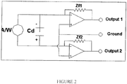
- Figure 2 is an alternative embodiment wherein a pair of FET input amplifiers are connected with resistors Zf1 and Zf2 a placed in a parallel combination.
- resistors Zf1 and Zf2 have a small capacitance of less than 5 pico Farads and a high ohmic value of resistance of about 100 Giga.
- Outputs 1 and Output 2 when connected differentially also have an output which is a factor of two greater than a normal standard single ended device, but also only produce noise which is only the square root of 2 or greater.
- the circuit additionally increased the signal to noise of the detector by a factor of the square root of the increase in signal or by about 1.41 times the standard single ended device.
Landscapes
- Physics & Mathematics (AREA)
- General Physics & Mathematics (AREA)
- Spectroscopy & Molecular Physics (AREA)
- Engineering & Computer Science (AREA)
- Power Engineering (AREA)
- Photometry And Measurement Of Optical Pulse Characteristics (AREA)
Claims (4)
- Eine differentielle pyroelektrische Infrarot-Detektorschaltung, umfassend:- einen pyroelektrischen Kristall mit zwei Elektroden;- zwei getrennte Impedanzwandlerschaltungen, wobei eine Impedanzwandlerschaltung mit einer der Elektroden und die andere Impedanzwandlerschaltung mit einer anderen der Elektroden des pyroelektrischen Kristalls verbunden ist, wobei jede der Impedanzwandlerschaltungen aus einem Verstärker gebildet ist und ein erstes und zweites niederohmiges Ausgangssignal (Ausgang 1, Ausgang 2) liefert; und- einen Differentialverstärker zum Empfang jedes der niederohmigen Ausgänge (Ausgang 1, Ausgang 2), so dass die beiden niederohmigen Ausgänge (Ausgang 1, Ausgang 2) differentiell verbunden sind;wobei entweder(i) die Verstärker, die die Impedanzwandlerschaltungen bilden, einen FET (Q1, Q2) umfassen, jede Elektrode des pyroelektrischen Kristalls direkt mit dem Eingang des jeweiligen FET verbunden ist und die pyroelektrische Infrarot-Differenzdetektorschaltung ferner eine Primärbrücke und eine Sekundärbrücke umfasst, wobei die Primärbrücke mit jeder der Elektroden des pyroelektrischen Kristalls und die Sekundärbrücke mit jedem der Verstärkerausgänge gekoppelt ist, wobei die Primärbrücke durch einen ersten Widerstand (R1) und einen zweiten Widerstand (R2) gebildet wird, die Primärbrücke ferner mit der Sekundärbrücke gekoppelt ist, die durch einen ersten Widerstand (Rs1) und einen zweiten Widerstand (Rs2) gebildet wird, und die Primärbrücke und die Sekundärbrücke mit dem Erdpotential verbunden sind,
oder(ii) wobei jeder der Verstärker, die die Impedanzwandlerschaltungen bilden, ein Operationsverstärker ist, der eine Widerstandsbrücke (Zf1, Zf2) aufweist, von denen jede den Ausgang mit dem invertierenden ("-") Eingang des entsprechenden Operationsverstärkers verbindet, die Elektroden des pyroelektrischen Kristalls direkt mit den invertierenden ("-") Eingängen der Operationsverstärker verbunden sind und wobei die nichtinvertierenden ("+") Eingänge der Operationsverstärker miteinander und mit dem Massepotential verbunden sind. - Die differentielle pyroelektrische Infrarot-Detektorschaltung nach Anspruch 1, wobei jeder der genannten Verstärker, der einen FET (Q1, Q2) umfasst, einen 2N4117-FET umfasst.
- Die differentielle pyroelektrische Infrarot-Detektorschaltung nach einem der vorhergehenden Ansprüche, wobei der erste Widerstand (R1) der Primärbrücke 1e11 Ohm und der zweite Widerstand (R2) der Primärbrücke 1e11 Ohm aufweist, wobei der erste Widerstand (Rs1) der Sekundärbrücke 100 kOhm und der zweite Widerstand (Rs2) der Sekundärbrücke 100 kOhm aufweist.
- Die differentielle pyroelektrische Infrarot-Detektorschaltung nach Anspruch 1, wobei jeder der Widerstände der Widerstandsbrücken (Zf1, Zf2) der Operationsverstärker eine kleine Kapazität von weniger als 5 Picofarad und einen hohen Widerstandswert von etwa 100 Giga Ohm aufweist.
Applications Claiming Priority (2)
| Application Number | Priority Date | Filing Date | Title |
|---|---|---|---|
| US201562132008P | 2015-03-12 | 2015-03-12 | |
| PCT/EP2016/055275 WO2016142512A1 (en) | 2015-03-12 | 2016-03-11 | Differential circuit for pyroelectric infrared detector |
Publications (2)
| Publication Number | Publication Date |
|---|---|
| EP3268706A1 EP3268706A1 (de) | 2018-01-17 |
| EP3268706B1 true EP3268706B1 (de) | 2020-10-28 |
Family
ID=55527564
Family Applications (1)
| Application Number | Title | Priority Date | Filing Date |
|---|---|---|---|
| EP16709772.4A Active EP3268706B1 (de) | 2015-03-12 | 2016-03-11 | Differentialschaltung für einen pyroelektrischen infrarotdetektor |
Country Status (4)
| Country | Link |
|---|---|
| US (1) | US10302500B2 (de) |
| EP (1) | EP3268706B1 (de) |
| DK (1) | DK3268706T3 (de) |
| WO (1) | WO2016142512A1 (de) |
Families Citing this family (1)
| Publication number | Priority date | Publication date | Assignee | Title |
|---|---|---|---|---|
| DK3268706T3 (da) * | 2015-03-12 | 2021-01-25 | Laser Components Gmbh | Differentialkredsløb til pyroelektrisk infrarød detektor |
Citations (2)
| Publication number | Priority date | Publication date | Assignee | Title |
|---|---|---|---|---|
| DE19727447A1 (de) * | 1996-09-06 | 1998-03-12 | Murata Manufacturing Co | Infrarotstrahlungsempfindliche Vorrichtung |
| WO1999044020A1 (en) * | 1998-02-27 | 1999-09-02 | C & K Systems, Inc. | Pyroelectric detector feedback amplifier low frequency response |
Family Cites Families (20)
| Publication number | Priority date | Publication date | Assignee | Title |
|---|---|---|---|---|
| US3161818A (en) * | 1961-10-04 | 1964-12-15 | Gen Electric | Transistor switching circuit utilizing variable impedance biasing means |
| US3453432A (en) | 1966-06-23 | 1969-07-01 | Barnes Eng Co | Pyroelectric radiation detector providing compensation for environmental temperature changes |
| US3839640A (en) | 1973-06-20 | 1974-10-01 | J Rossin | Differential pyroelectric sensor |
| US3877308A (en) | 1974-01-02 | 1975-04-15 | Minnesota Mining & Mfg | Pyroelectric temperature compensated sensing apparatus |
| US4441023A (en) * | 1981-07-29 | 1984-04-03 | Eltec Instruments, Inc. | High output differential pyroelectric sensor |
| US5468960A (en) * | 1993-05-12 | 1995-11-21 | Optex Co., Ltd. | Pyroelectric infrared detector |
| JP3664041B2 (ja) * | 2000-05-17 | 2005-06-22 | 株式会社村田製作所 | 電荷型センサ用増幅回路 |
| GB0202506D0 (en) * | 2002-02-02 | 2002-03-20 | Qinetiq Ltd | Reconfigurable detector array |
| CN101437777B (zh) * | 2006-04-28 | 2013-09-11 | 株式会社村田制作所 | 热电性陶瓷组合物、热电元件以及红外线检测器 |
| US8946538B2 (en) * | 2009-05-14 | 2015-02-03 | The Neothermal Energy Company | Method and apparatus for generating electricity by thermally cycling an electrically polarizable material using heat from condensers |
| JP2011058861A (ja) * | 2009-09-08 | 2011-03-24 | Panasonic Corp | 焦電型赤外線検出器 |
| WO2012002496A1 (ja) * | 2010-07-01 | 2012-01-05 | パナソニック電工株式会社 | 対象物検出装置 |
| US8471639B2 (en) * | 2010-07-06 | 2013-06-25 | Luxtera Inc. | Method and system for a feedback transimpedance amplifier with sub-40khz low-frequency cutoff |
| DE102010062648A1 (de) | 2010-12-08 | 2012-06-14 | Kuka Roboter Gmbh | Telepräsenzsystem |
| CN102681311B (zh) * | 2011-03-11 | 2014-09-03 | 中强光电股份有限公司 | 控制电路与投影装置的操作方法 |
| US20140042320A1 (en) * | 2012-08-08 | 2014-02-13 | Excelitas Technologies Singapore Pte. Ltd. | Emi filtering detector and method for same |
| CN103825474B (zh) * | 2012-11-16 | 2016-08-31 | 台达电子工业股份有限公司 | 低共模噪声的电源变换装置及其应用系统 |
| WO2015088470A1 (en) * | 2013-12-09 | 2015-06-18 | Greenwave Systems, Pte. Ltd. | Motion detection |
| DK3268706T3 (da) * | 2015-03-12 | 2021-01-25 | Laser Components Gmbh | Differentialkredsløb til pyroelektrisk infrarød detektor |
| CN106033225B (zh) * | 2015-03-16 | 2017-08-25 | 苏州旭创科技有限公司 | 低功耗apd偏压控制器与偏压控制方法及光电接收器 |
-
2016
- 2016-03-11 DK DK16709772.4T patent/DK3268706T3/da active
- 2016-03-11 WO PCT/EP2016/055275 patent/WO2016142512A1/en not_active Ceased
- 2016-03-11 US US15/556,041 patent/US10302500B2/en active Active
- 2016-03-11 EP EP16709772.4A patent/EP3268706B1/de active Active
Patent Citations (2)
| Publication number | Priority date | Publication date | Assignee | Title |
|---|---|---|---|---|
| DE19727447A1 (de) * | 1996-09-06 | 1998-03-12 | Murata Manufacturing Co | Infrarotstrahlungsempfindliche Vorrichtung |
| WO1999044020A1 (en) * | 1998-02-27 | 1999-09-02 | C & K Systems, Inc. | Pyroelectric detector feedback amplifier low frequency response |
Non-Patent Citations (3)
| Title |
|---|
| ANONYMOUS: "Operational amplifier - Wikipedia", 9 March 2015 (2015-03-09), XP055610434, Retrieved from the Internet <URL:https://en.wikipedia.org/w/index.php?title=Operational_amplifier&oldid=650639737> [retrieved on 20190801] * |
| ANONYMOUS: "Transimpedance amplifier - Wikipedia, the free encyclopedia", 11 July 2014 (2014-07-11), XP055205526, Retrieved from the Internet <URL:https://en.wikipedia.org/w/index.php?title=Transimpedance_amplifier&oldid=616480844> [retrieved on 20150730] * |
| WIKIPEDIA: "Common drain", 20 November 2013 (2013-11-20), XP055339824, Retrieved from the Internet <URL:https://en.wikipedia.org/w/index.php?title=Special:Book&bookcmd=download&collection_id=bdfda97614eb62ded23c509ffe5bc856fdfa3277&writer=rdf2latex&return_to=Common+drain> [retrieved on 20170127] * |
Also Published As
| Publication number | Publication date |
|---|---|
| DK3268706T3 (da) | 2021-01-25 |
| US10302500B2 (en) | 2019-05-28 |
| EP3268706A1 (de) | 2018-01-17 |
| US20180058937A1 (en) | 2018-03-01 |
| WO2016142512A1 (en) | 2016-09-15 |
Similar Documents
| Publication | Publication Date | Title |
|---|---|---|
| US5045702A (en) | Infrared intrustion detector | |
| US3839640A (en) | Differential pyroelectric sensor | |
| US4441023A (en) | High output differential pyroelectric sensor | |
| CN107112990B (zh) | 电容传感器 | |
| US4437003A (en) | Differential pyroelectric sensor with static discharge | |
| US6339221B1 (en) | Ferroelectric thermometry and pyrometry by active operation | |
| US5414263A (en) | Infrared detection switching circuit | |
| US7042134B2 (en) | Transconductance circuit for piezoelectric transducer | |
| KR102176201B1 (ko) | 인체 검출 장치 | |
| US10302500B2 (en) | Differential circuit for pyroelectric infrared detector | |
| US20040164647A1 (en) | Piezoelectric transducer circuit with improved shock recovery | |
| WO2015048463A1 (en) | Sensor signal processing using cascade coupled oscillators | |
| US6294784B1 (en) | Pyroelectric sensor sensitivity enhanced by active hysteresis excitation | |
| CN104155010A (zh) | 一种计数热释电红外传感器 | |
| JPH05281035A (ja) | 焦電型赤外線検出器 | |
| CN105938018A (zh) | 一种热释电探测器 | |
| JPH0216459B2 (de) | ||
| Moroz et al. | Investigation of Features of Functioning of the Pyroelectric Sensors in Electronic Security Devices | |
| US8878131B2 (en) | Pin-compatible infrared light detector having improved thermal stability | |
| CN204609612U (zh) | 高敏度传感器的信号检测电路 | |
| JP3005171B2 (ja) | 受動型赤外線検知装置 | |
| EP3896665A1 (de) | Vorrichtung und verfahren zur anwesenheitserkennung, insbesondere für eindringschutzsysteme | |
| JP3317117B2 (ja) | 焦電型赤外線センサ | |
| JP2983424B2 (ja) | 焦電型赤外線検知器 | |
| JPH04287Y2 (de) |
Legal Events
| Date | Code | Title | Description |
|---|---|---|---|
| STAA | Information on the status of an ep patent application or granted ep patent |
Free format text: STATUS: THE INTERNATIONAL PUBLICATION HAS BEEN MADE |
|
| PUAI | Public reference made under article 153(3) epc to a published international application that has entered the european phase |
Free format text: ORIGINAL CODE: 0009012 |
|
| STAA | Information on the status of an ep patent application or granted ep patent |
Free format text: STATUS: REQUEST FOR EXAMINATION WAS MADE |
|
| 17P | Request for examination filed |
Effective date: 20170925 |
|
| AK | Designated contracting states |
Kind code of ref document: A1 Designated state(s): AL AT BE BG CH CY CZ DE DK EE ES FI FR GB GR HR HU IE IS IT LI LT LU LV MC MK MT NL NO PL PT RO RS SE SI SK SM TR |
|
| AX | Request for extension of the european patent |
Extension state: BA ME |
|
| DAV | Request for validation of the european patent (deleted) | ||
| DAX | Request for extension of the european patent (deleted) | ||
| STAA | Information on the status of an ep patent application or granted ep patent |
Free format text: STATUS: EXAMINATION IS IN PROGRESS |
|
| 17Q | First examination report despatched |
Effective date: 20190814 |
|
| GRAP | Despatch of communication of intention to grant a patent |
Free format text: ORIGINAL CODE: EPIDOSNIGR1 |
|
| STAA | Information on the status of an ep patent application or granted ep patent |
Free format text: STATUS: GRANT OF PATENT IS INTENDED |
|
| INTG | Intention to grant announced |
Effective date: 20200714 |
|
| GRAS | Grant fee paid |
Free format text: ORIGINAL CODE: EPIDOSNIGR3 |
|
| GRAA | (expected) grant |
Free format text: ORIGINAL CODE: 0009210 |
|
| STAA | Information on the status of an ep patent application or granted ep patent |
Free format text: STATUS: THE PATENT HAS BEEN GRANTED |
|
| AK | Designated contracting states |
Kind code of ref document: B1 Designated state(s): AL AT BE BG CH CY CZ DE DK EE ES FI FR GB GR HR HU IE IS IT LI LT LU LV MC MK MT NL NO PL PT RO RS SE SI SK SM TR |
|
| REG | Reference to a national code |
Ref country code: GB Ref legal event code: FG4D |
|
| REG | Reference to a national code |
Ref country code: CH Ref legal event code: EP |
|
| REG | Reference to a national code |
Ref country code: AT Ref legal event code: REF Ref document number: 1328670 Country of ref document: AT Kind code of ref document: T Effective date: 20201115 |
|
| REG | Reference to a national code |
Ref country code: DE Ref legal event code: R096 Ref document number: 602016046653 Country of ref document: DE |
|
| REG | Reference to a national code |
Ref country code: IE Ref legal event code: FG4D |
|
| REG | Reference to a national code |
Ref country code: FI Ref legal event code: FGE |
|
| REG | Reference to a national code |
Ref country code: DK Ref legal event code: T3 Effective date: 20210120 |
|
| REG | Reference to a national code |
Ref country code: SE Ref legal event code: TRGR |
|
| REG | Reference to a national code |
Ref country code: NO Ref legal event code: T2 Effective date: 20201028 |
|
| PG25 | Lapsed in a contracting state [announced via postgrant information from national office to epo] |
Ref country code: RS Free format text: LAPSE BECAUSE OF FAILURE TO SUBMIT A TRANSLATION OF THE DESCRIPTION OR TO PAY THE FEE WITHIN THE PRESCRIBED TIME-LIMIT Effective date: 20201028 Ref country code: PT Free format text: LAPSE BECAUSE OF FAILURE TO SUBMIT A TRANSLATION OF THE DESCRIPTION OR TO PAY THE FEE WITHIN THE PRESCRIBED TIME-LIMIT Effective date: 20210301 Ref country code: GR Free format text: LAPSE BECAUSE OF FAILURE TO SUBMIT A TRANSLATION OF THE DESCRIPTION OR TO PAY THE FEE WITHIN THE PRESCRIBED TIME-LIMIT Effective date: 20210129 |
|
| REG | Reference to a national code |
Ref country code: LT Ref legal event code: MG4D |
|
| PG25 | Lapsed in a contracting state [announced via postgrant information from national office to epo] |
Ref country code: LV Free format text: LAPSE BECAUSE OF FAILURE TO SUBMIT A TRANSLATION OF THE DESCRIPTION OR TO PAY THE FEE WITHIN THE PRESCRIBED TIME-LIMIT Effective date: 20201028 Ref country code: IS Free format text: LAPSE BECAUSE OF FAILURE TO SUBMIT A TRANSLATION OF THE DESCRIPTION OR TO PAY THE FEE WITHIN THE PRESCRIBED TIME-LIMIT Effective date: 20210228 Ref country code: PL Free format text: LAPSE BECAUSE OF FAILURE TO SUBMIT A TRANSLATION OF THE DESCRIPTION OR TO PAY THE FEE WITHIN THE PRESCRIBED TIME-LIMIT Effective date: 20201028 Ref country code: BG Free format text: LAPSE BECAUSE OF FAILURE TO SUBMIT A TRANSLATION OF THE DESCRIPTION OR TO PAY THE FEE WITHIN THE PRESCRIBED TIME-LIMIT Effective date: 20210128 Ref country code: ES Free format text: LAPSE BECAUSE OF FAILURE TO SUBMIT A TRANSLATION OF THE DESCRIPTION OR TO PAY THE FEE WITHIN THE PRESCRIBED TIME-LIMIT Effective date: 20201028 |
|
| PG25 | Lapsed in a contracting state [announced via postgrant information from national office to epo] |
Ref country code: HR Free format text: LAPSE BECAUSE OF FAILURE TO SUBMIT A TRANSLATION OF THE DESCRIPTION OR TO PAY THE FEE WITHIN THE PRESCRIBED TIME-LIMIT Effective date: 20201028 |
|
| REG | Reference to a national code |
Ref country code: DE Ref legal event code: R097 Ref document number: 602016046653 Country of ref document: DE |
|
| PG25 | Lapsed in a contracting state [announced via postgrant information from national office to epo] |
Ref country code: SM Free format text: LAPSE BECAUSE OF FAILURE TO SUBMIT A TRANSLATION OF THE DESCRIPTION OR TO PAY THE FEE WITHIN THE PRESCRIBED TIME-LIMIT Effective date: 20201028 Ref country code: LT Free format text: LAPSE BECAUSE OF FAILURE TO SUBMIT A TRANSLATION OF THE DESCRIPTION OR TO PAY THE FEE WITHIN THE PRESCRIBED TIME-LIMIT Effective date: 20201028 Ref country code: EE Free format text: LAPSE BECAUSE OF FAILURE TO SUBMIT A TRANSLATION OF THE DESCRIPTION OR TO PAY THE FEE WITHIN THE PRESCRIBED TIME-LIMIT Effective date: 20201028 Ref country code: CZ Free format text: LAPSE BECAUSE OF FAILURE TO SUBMIT A TRANSLATION OF THE DESCRIPTION OR TO PAY THE FEE WITHIN THE PRESCRIBED TIME-LIMIT Effective date: 20201028 Ref country code: RO Free format text: LAPSE BECAUSE OF FAILURE TO SUBMIT A TRANSLATION OF THE DESCRIPTION OR TO PAY THE FEE WITHIN THE PRESCRIBED TIME-LIMIT Effective date: 20201028 Ref country code: SK Free format text: LAPSE BECAUSE OF FAILURE TO SUBMIT A TRANSLATION OF THE DESCRIPTION OR TO PAY THE FEE WITHIN THE PRESCRIBED TIME-LIMIT Effective date: 20201028 |
|
| PLBE | No opposition filed within time limit |
Free format text: ORIGINAL CODE: 0009261 |
|
| STAA | Information on the status of an ep patent application or granted ep patent |
Free format text: STATUS: NO OPPOSITION FILED WITHIN TIME LIMIT |
|
| 26N | No opposition filed |
Effective date: 20210729 |
|
| REG | Reference to a national code |
Ref country code: NL Ref legal event code: FP |
|
| PG25 | Lapsed in a contracting state [announced via postgrant information from national office to epo] |
Ref country code: IT Free format text: LAPSE BECAUSE OF FAILURE TO SUBMIT A TRANSLATION OF THE DESCRIPTION OR TO PAY THE FEE WITHIN THE PRESCRIBED TIME-LIMIT Effective date: 20201028 Ref country code: AL Free format text: LAPSE BECAUSE OF FAILURE TO SUBMIT A TRANSLATION OF THE DESCRIPTION OR TO PAY THE FEE WITHIN THE PRESCRIBED TIME-LIMIT Effective date: 20201028 Ref country code: MC Free format text: LAPSE BECAUSE OF FAILURE TO SUBMIT A TRANSLATION OF THE DESCRIPTION OR TO PAY THE FEE WITHIN THE PRESCRIBED TIME-LIMIT Effective date: 20201028 |
|
| PG25 | Lapsed in a contracting state [announced via postgrant information from national office to epo] |
Ref country code: SI Free format text: LAPSE BECAUSE OF FAILURE TO SUBMIT A TRANSLATION OF THE DESCRIPTION OR TO PAY THE FEE WITHIN THE PRESCRIBED TIME-LIMIT Effective date: 20201028 |
|
| PG25 | Lapsed in a contracting state [announced via postgrant information from national office to epo] |
Ref country code: LU Free format text: LAPSE BECAUSE OF NON-PAYMENT OF DUE FEES Effective date: 20210311 |
|
| PGFP | Annual fee paid to national office [announced via postgrant information from national office to epo] |
Ref country code: IE Payment date: 20220322 Year of fee payment: 7 Ref country code: FI Payment date: 20220318 Year of fee payment: 7 Ref country code: CH Payment date: 20220324 Year of fee payment: 7 Ref country code: AT Payment date: 20220318 Year of fee payment: 7 Ref country code: DK Payment date: 20220322 Year of fee payment: 7 |
|
| PG25 | Lapsed in a contracting state [announced via postgrant information from national office to epo] |
Ref country code: IS Free format text: LAPSE BECAUSE OF FAILURE TO SUBMIT A TRANSLATION OF THE DESCRIPTION OR TO PAY THE FEE WITHIN THE PRESCRIBED TIME-LIMIT Effective date: 20210228 |
|
| PGFP | Annual fee paid to national office [announced via postgrant information from national office to epo] |
Ref country code: NO Payment date: 20220322 Year of fee payment: 7 Ref country code: BE Payment date: 20220322 Year of fee payment: 7 |
|
| REG | Reference to a national code |
Ref country code: NO Ref legal event code: CHAD Owner name: PHOTONA GMBH, DE |
|
| REG | Reference to a national code |
Ref country code: FI Ref legal event code: PCE Owner name: PHOTONA GMBH |
|
| REG | Reference to a national code |
Ref country code: BE Ref legal event code: HC Owner name: PHOTONA GMBH; DE Free format text: DETAILS ASSIGNMENT: CHANGE OF OWNER(S), CHANGE OF OWNER(S) NAME; FORMER OWNER NAME: LASER COMPONENTS GMBH Effective date: 20220530 |
|
| REG | Reference to a national code |
Ref country code: DE Ref legal event code: R081 Ref document number: 602016046653 Country of ref document: DE Owner name: PHOTONA GMBH, DE Free format text: FORMER OWNER: LASER COMPONENTS GMBH, 82140 OLCHING, DE |
|
| REG | Reference to a national code |
Ref country code: NL Ref legal event code: HC Owner name: PHOTONA GMBH; DE Free format text: DETAILS ASSIGNMENT: CHANGE OF OWNER(S), CHANGE OF OWNER(S) NAME; FORMER OWNER NAME: LASER COMPONENTS GMBH Effective date: 20220628 |
|
| REG | Reference to a national code |
Ref country code: AT Ref legal event code: HC Ref document number: 1328670 Country of ref document: AT Kind code of ref document: T Owner name: PHOTONA GMBH, DE Effective date: 20221025 |
|
| REG | Reference to a national code |
Ref country code: AT Ref legal event code: UEP Ref document number: 1328670 Country of ref document: AT Kind code of ref document: T Effective date: 20201028 |
|
| PG25 | Lapsed in a contracting state [announced via postgrant information from national office to epo] |
Ref country code: CY Free format text: LAPSE BECAUSE OF FAILURE TO SUBMIT A TRANSLATION OF THE DESCRIPTION OR TO PAY THE FEE WITHIN THE PRESCRIBED TIME-LIMIT Effective date: 20201028 |
|
| PG25 | Lapsed in a contracting state [announced via postgrant information from national office to epo] |
Ref country code: HU Free format text: LAPSE BECAUSE OF FAILURE TO SUBMIT A TRANSLATION OF THE DESCRIPTION OR TO PAY THE FEE WITHIN THE PRESCRIBED TIME-LIMIT; INVALID AB INITIO Effective date: 20160311 |
|
| REG | Reference to a national code |
Ref country code: NO Ref legal event code: MMEP |
|
| PG25 | Lapsed in a contracting state [announced via postgrant information from national office to epo] |
Ref country code: FI Free format text: LAPSE BECAUSE OF NON-PAYMENT OF DUE FEES Effective date: 20230311 |
|
| REG | Reference to a national code |
Ref country code: CH Ref legal event code: PL |
|
| REG | Reference to a national code |
Ref country code: DK Ref legal event code: EBP Effective date: 20230331 |
|
| REG | Reference to a national code |
Ref country code: AT Ref legal event code: MM01 Ref document number: 1328670 Country of ref document: AT Kind code of ref document: T Effective date: 20230311 |
|
| REG | Reference to a national code |
Ref country code: BE Ref legal event code: MM Effective date: 20230331 |
|
| REG | Reference to a national code |
Ref country code: IE Ref legal event code: MM4A |
|
| PG25 | Lapsed in a contracting state [announced via postgrant information from national office to epo] |
Ref country code: NO Free format text: LAPSE BECAUSE OF NON-PAYMENT OF DUE FEES Effective date: 20230331 Ref country code: LI Free format text: LAPSE BECAUSE OF NON-PAYMENT OF DUE FEES Effective date: 20230331 Ref country code: IE Free format text: LAPSE BECAUSE OF NON-PAYMENT OF DUE FEES Effective date: 20230311 Ref country code: CH Free format text: LAPSE BECAUSE OF NON-PAYMENT OF DUE FEES Effective date: 20230331 Ref country code: AT Free format text: LAPSE BECAUSE OF NON-PAYMENT OF DUE FEES Effective date: 20230311 |
|
| PG25 | Lapsed in a contracting state [announced via postgrant information from national office to epo] |
Ref country code: BE Free format text: LAPSE BECAUSE OF NON-PAYMENT OF DUE FEES Effective date: 20230331 |
|
| PG25 | Lapsed in a contracting state [announced via postgrant information from national office to epo] |
Ref country code: MK Free format text: LAPSE BECAUSE OF FAILURE TO SUBMIT A TRANSLATION OF THE DESCRIPTION OR TO PAY THE FEE WITHIN THE PRESCRIBED TIME-LIMIT Effective date: 20201028 Ref country code: DK Free format text: LAPSE BECAUSE OF NON-PAYMENT OF DUE FEES Effective date: 20230331 |
|
| PG25 | Lapsed in a contracting state [announced via postgrant information from national office to epo] |
Ref country code: TR Free format text: LAPSE BECAUSE OF FAILURE TO SUBMIT A TRANSLATION OF THE DESCRIPTION OR TO PAY THE FEE WITHIN THE PRESCRIBED TIME-LIMIT Effective date: 20201028 |
|
| PG25 | Lapsed in a contracting state [announced via postgrant information from national office to epo] |
Ref country code: MT Free format text: LAPSE BECAUSE OF FAILURE TO SUBMIT A TRANSLATION OF THE DESCRIPTION OR TO PAY THE FEE WITHIN THE PRESCRIBED TIME-LIMIT Effective date: 20201028 |
|
| PGFP | Annual fee paid to national office [announced via postgrant information from national office to epo] |
Ref country code: SE Payment date: 20260323 Year of fee payment: 11 |
|
| PGFP | Annual fee paid to national office [announced via postgrant information from national office to epo] |
Ref country code: GB Payment date: 20260324 Year of fee payment: 11 |
|
| PGFP | Annual fee paid to national office [announced via postgrant information from national office to epo] |
Ref country code: DE Payment date: 20260318 Year of fee payment: 11 |
|
| PGFP | Annual fee paid to national office [announced via postgrant information from national office to epo] |
Ref country code: NL Payment date: 20260323 Year of fee payment: 11 |
|
| PGFP | Annual fee paid to national office [announced via postgrant information from national office to epo] |
Ref country code: FR Payment date: 20260325 Year of fee payment: 11 |