EP3268785B1 - Überziehmuffenanordnung für glasfaserkabelendstück - Google Patents
Überziehmuffenanordnung für glasfaserkabelendstück Download PDFInfo
- Publication number
- EP3268785B1 EP3268785B1 EP16762360.2A EP16762360A EP3268785B1 EP 3268785 B1 EP3268785 B1 EP 3268785B1 EP 16762360 A EP16762360 A EP 16762360A EP 3268785 B1 EP3268785 B1 EP 3268785B1
- Authority
- EP
- European Patent Office
- Prior art keywords
- fiber optic
- terminus
- assembly
- overboot
- receptacle
- Prior art date
- Legal status (The legal status is an assumption and is not a legal conclusion. Google has not performed a legal analysis and makes no representation as to the accuracy of the status listed.)
- Active
Links
Images



Classifications
-
- G—PHYSICS
- G02—OPTICS
- G02B—OPTICAL ELEMENTS, SYSTEMS OR APPARATUS
- G02B6/00—Light guides; Structural details of arrangements comprising light guides and other optical elements, e.g. couplings
- G02B6/24—Coupling light guides
- G02B6/36—Mechanical coupling means
- G02B6/38—Mechanical coupling means having fibre to fibre mating means
- G02B6/3807—Dismountable connectors, i.e. comprising plugs
- G02B6/381—Dismountable connectors, i.e. comprising plugs of the ferrule type, e.g. fibre ends embedded in ferrules, connecting a pair of fibres
- G02B6/3818—Dismountable connectors, i.e. comprising plugs of the ferrule type, e.g. fibre ends embedded in ferrules, connecting a pair of fibres of a low-reflection-loss type
- G02B6/3821—Dismountable connectors, i.e. comprising plugs of the ferrule type, e.g. fibre ends embedded in ferrules, connecting a pair of fibres of a low-reflection-loss type with axial spring biasing or loading means
-
- G—PHYSICS
- G02—OPTICS
- G02B—OPTICAL ELEMENTS, SYSTEMS OR APPARATUS
- G02B6/00—Light guides; Structural details of arrangements comprising light guides and other optical elements, e.g. couplings
- G02B6/24—Coupling light guides
- G02B6/36—Mechanical coupling means
- G02B6/38—Mechanical coupling means having fibre to fibre mating means
- G02B6/3807—Dismountable connectors, i.e. comprising plugs
- G02B6/381—Dismountable connectors, i.e. comprising plugs of the ferrule type, e.g. fibre ends embedded in ferrules, connecting a pair of fibres
- G02B6/3825—Dismountable connectors, i.e. comprising plugs of the ferrule type, e.g. fibre ends embedded in ferrules, connecting a pair of fibres with an intermediate part, e.g. adapter, receptacle, linking two plugs
-
- G—PHYSICS
- G02—OPTICS
- G02B—OPTICAL ELEMENTS, SYSTEMS OR APPARATUS
- G02B6/00—Light guides; Structural details of arrangements comprising light guides and other optical elements, e.g. couplings
- G02B6/24—Coupling light guides
- G02B6/36—Mechanical coupling means
- G02B6/38—Mechanical coupling means having fibre to fibre mating means
- G02B6/3807—Dismountable connectors, i.e. comprising plugs
- G02B6/3887—Anchoring optical cables to connector housings, e.g. strain relief features
- G02B6/3889—Anchoring optical cables to connector housings, e.g. strain relief features using encapsulation for protection, e.g. adhesive, molding or casting resin
-
- G—PHYSICS
- G02—OPTICS
- G02B—OPTICAL ELEMENTS, SYSTEMS OR APPARATUS
- G02B6/00—Light guides; Structural details of arrangements comprising light guides and other optical elements, e.g. couplings
- G02B6/24—Coupling light guides
- G02B6/36—Mechanical coupling means
- G02B6/38—Mechanical coupling means having fibre to fibre mating means
- G02B6/3807—Dismountable connectors, i.e. comprising plugs
- G02B6/389—Dismountable connectors, i.e. comprising plugs characterised by the method of fastening connecting plugs and sockets, e.g. screw- or nut-lock, snap-in, bayonet type
- G02B6/3893—Push-pull type, e.g. snap-in, push-on
-
- G—PHYSICS
- G02—OPTICS
- G02B—OPTICAL ELEMENTS, SYSTEMS OR APPARATUS
- G02B6/00—Light guides; Structural details of arrangements comprising light guides and other optical elements, e.g. couplings
- G02B6/24—Coupling light guides
- G02B6/36—Mechanical coupling means
- G02B6/38—Mechanical coupling means having fibre to fibre mating means
- G02B6/3807—Dismountable connectors, i.e. comprising plugs
- G02B6/3887—Anchoring optical cables to connector housings, e.g. strain relief features
- G02B6/3888—Protection from over-extension or over-compression
-
- G—PHYSICS
- G02—OPTICS
- G02B—OPTICAL ELEMENTS, SYSTEMS OR APPARATUS
- G02B6/00—Light guides; Structural details of arrangements comprising light guides and other optical elements, e.g. couplings
- G02B6/24—Coupling light guides
- G02B6/42—Coupling light guides with opto-electronic elements
- G02B6/4201—Packages, e.g. shape, construction, internal or external details
- G02B6/4256—Details of housings
- G02B6/426—Details of housings mounting, engaging or coupling of the package to a board, a frame or a panel
- G02B6/4261—Packages with mounting structures to be pluggable or detachable, e.g. having latches or rails
-
- G—PHYSICS
- G02—OPTICS
- G02B—OPTICAL ELEMENTS, SYSTEMS OR APPARATUS
- G02B6/00—Light guides; Structural details of arrangements comprising light guides and other optical elements, e.g. couplings
- G02B6/24—Coupling light guides
- G02B6/42—Coupling light guides with opto-electronic elements
- G02B6/4292—Coupling light guides with opto-electronic elements the light guide being disconnectable from the opto-electronic element, e.g. mutually self aligning arrangements
Definitions
- Fiber optic links are often used to replace existing electrical (e.g., "copper") wiring architectures. Fiber optic links provide higher speed, improved electro-magnetic interference (EMI) performance, lower weight, and increased density. Other advantages of fiber optic links include higher data capacity using multiple light propagation modes. In addition, the fiber optic cable itself is protocol agnostic. Therefore, system upgrades often may be made without replacing the fiber optic cable.
- EMI electro-magnetic interference
- Fiber optic products are designed for the telecommunications market. But these products are generally not rugged enough to withstand the environmental factors that would adversely affect fiber optic systems in harsh operating environments where extreme states of vibration, shock, and temperature may be present.
- One common connector (also referred to as terminus) that is used to establish a rugged connection with a mating receptacle is a terminus that is compliant with the ARINC 801 standard in the Size 16 form factor (also referred to herein as an ARINC 801 terminus or, in the plural form, ARINC 801 termini).
- ARINC 801 termini have been adopted in a variety of military and aerospace applications.
- ARINC 801 termini lack components to provide cable strain relief directly on the termini and must be supported within the connector into which they are inserted. Also, removal of an ARINC 801 terminus from a mating receptacle requires a separate tool.
- the tool must be provided by a person servicing the optical system since the tool is not part of the optical system itself. Therefore, the tool is not always readily available or configured to fit within the space in which the terminus and receptacle are located.
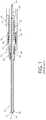
- FIG. 1 illustrates a longitudinal cross-section of a conventional ARINC 801 terminus 10 connected to the terminal end of a fiber optic cable 12.
- the assembly of the fiber optic cable 12 and the ARINC 801 terminus 10 may be referred to as an ARINC 801 terminated fiber cable.
- the fiber optic cable 12 includes a fiber optic filament 14 that is surrounded by one or more coating layers 16.
- the fiber optic filament 14 typically includes a core and a cladding.
- the coating layers 16 are surrounded by strength members 18, such as KEVLAR fibers.
- One or more jacketing layers, also referred to as a jacket 20 surround the strength members 18.
- the terminus 10 includes a tubular body 22, a ferrule 24 and a crimp sleeve 26.
- the jacket 20 and strength members 18 are captured between the crimp sleeve 26 and a land portion 28 at a rearward end of the body 22.
- the coating layers 16 are partially stripped from the fiber optic filament 14 and the ferrule 24 is secured to the filament 14 and/or coating layers 16, as is typical for fiber optic connectors.
- the ferrule 24 and forward end 30 of the filament 14 are urged in a forward direction relative to the body 22 under the force of a spring 32.
- An internal shoulder 34 in the body 22 provides a surface against which the rearward end of the spring 32 acts. Compression of the crimp sleeve 26 against the jacket 20, strength members 18 and rearward portion of the body 22 limit longitudinal movement of the body 22 relative to the fiber optic cable 12.
- the terminus 10 is inserted into and retained by a receptacle 38 to establish an operative optical coupling between the filament 14 and an optical component (not shown in FIG. 1 ) that is located in the receptacle. Retaining of the terminus 10 may be accomplished by engagement of ends of deflectable fingers 40 against an external shoulder 36 of the body 22.
- Release of the terminus 10 from the receptacle is accomplished by placing a "C" shaped sleeve of a removal tool (not shown) around the fiber optic cable 12 and advancing the sleeve in a forward direction under the ends of the deflectable fingers 40 to move the fingers outward in a radial direction a sufficient distance so that the fingers no longer trap the body 22 in the receptacle.
- a removal tool not shown
- such a tool is not always readily available or configured to fit within the space in which the terminus and receptacle are located.
- such a tool is difficult to use in a proper manner to avoid damage to the fiber optic cable or terminus.
- terminus 10 and the receptacle 38 are keyed. As such, proper insertion of the terminus 10 into the receptacle includes angular alignment of the respective keying features.
- a keying feature of the terminus 10 may include a radial projection and the keying feature of the receptacle 38 may be a coordinating slot in a housing 42 of the receptacle 38 that forms a longitudinal passage 44 for receiving the terminus 10.
- Document US5940559 discloses a fiber-optic test probe and connector adapter for testing fiber-optic terminations in fiber optic connector assemblies.
- a single and multi-channel connector adapter is provided that is adapted to be attached to the fiber-optic connector to be tested.
- the connector adapter includes an alignment sleeve that enables the terminus of the fiber-optic connector to be tested to be axially aligned with the terminus of the test probe.
- the fiber-optic test probe and connector adapter are configured to provide axial compression forces between the mating termini in a test position in order to eliminate air gaps therebetween and thus reduce transmission losses.
- the test probe includes a release sleeve that allows the test probe to be quickly released from its locked position.
- the invention describes an overboot assembly for a fiber optic assembly according to claim 1. Different embodiments of the invention are set out in the dependent claims.
- connector for the terminal end connecting assembly of a fiber optic cable
- terminus for the same or similar connecting assembly. This largely depends on the application.
- persons of ordinary skill in the art in telecommunications typically use the term connector and persons of ordinary skill in the art in the military and avionics fields typically use the term terminus.
- the term connector and terminus have the same meaning.
- FIGs. 2, 3 and 4 a representative embodiment of an overboot assembly 100 for a terminus 10 ( FIG. 4 ) for a fiber optic cable 12 is illustrated.
- the fiber optic cable 12 and terminus 10 are as described in connection with FIG. 1 . Therefore, in the illustrated embodiment, the terminus 10 is a terminus compliant with the ARINC 801 standard in the Size 16 form factor and the reference numerals used in connection with FIG. 1 are used throughout.
- the illustrated terminus 10 retains one fiber optic cable 12 and, therefore, one fiber optic filament 14. In other embodiment, the terminus 10 may retain more than one fiber optic cable 12 and/or more than one fiber optic filament 14.
- the overboot assembly is a combined strain relief and insertion/removal tool for a terminated fiber optic cable.
- the overboot assembly 100 includes a removal member 102, a spring 104, a spring anchor 106, a cable standoff 108, a cable retention member (CRM) 110 and a cover 112.
- the overboot assembly 100 may include fewer components, additional components, or different components that serve the same or similar functional purposes.
- the CRM 110 and the spring anchor 106 may be combined.
- the CRM 110 is secured to the jacket 20 of the fiber optic cable 12 by mechanical interference so that the CRM 110 is longitudinally fixed in location relative to the fiber optic cable 12.
- the CRM 110 may be secured to the fiber optic cable 12 using adhesive or another securing means.
- the CRM 110 is located relative to the crimp sleeve 26 of the terminus 10 to longitudinally trap the spring anchor 106 and the cable standoff 108 between the crimp sleeve 26 and CRM 110.
- the locations of the anchor 106 and the standoff 108 will be fixed relative to the fiber optic cable 12 since the crimp sleeve 26 and the CRM 110 will limit longitudinal travel of the anchor 106 and the standoff 108.
- a static end of the spring 104 is held by the spring anchor 106.
- the exterior surface of the spring anchor 106 is threaded and the spring 104 is threaded onto the threads of the spring anchor 106.
- the cover 112 may be configured to cover the spring 104, the spring anchor 106, the CRM 110, and a portion of the fiber optic cable 12 rearward of the CRM 110.
- the standoff 108 radially separates the fiber optic cable 12 and the spring 104 to allow for relatively smooth extension and retraction of the spring 104 during use of the removal member 102, as will be described below.
- the standoff 108 is made from low friction material.
- the removal member 102 may be tubular in nature and may include a grip 114 and a sleeve 116.
- the grip 114 and sleeve 116 are two components that are joined together by an interference fit, swaging, adhesive, or some other fastening technique.
- the grip 114 and sleeve 116 are respective portions of a monolithic element. In either case, longitudinal movement of the grip 114 under manipulation of a user's fingers or a tool results in coordinated longitudinal movement of the sleeve 116.
- the grip 114 is connected to the dynamic end of the spring 104. In the illustrated embodiment, the interior surface of the grip 114 is threaded and the spring 104 is threaded onto the threads of the grip 114.
- Thread locking adhesive or other fastening technique may be used to prevent separation of the spring 104 from the spring anchor 106 and/or the removal member 102 in the event that the removal member 102 is rotated relative to the spring 104 or the spring 104 is rotated relative to the spring anchor 106.
- the spring 104 is configured to have a normally compressed state to bias the removal member 102 in the rearward direction.
- the return force of the spring 104 may be overcome by urging the removal member 102 in a forward direction.
- the return force of the spring 104 in conjunction with damping forces due to friction between spring 104 and cover 112, and between standoff 108 and grip 114, is preferably greater than longitudinally forward force that may be placed on the removal member 102 in ordinary operating conditions of the optical system in which the terminus 10 employed. Therefore, it is contemplated that forces such mechanical stress, vibration, shock, etc. will not significantly advance the removal member 102 in the forward direction relative to the fiber optic cable 12 by an amount to unlatch the terminus 10 from a coordinating receptacle.
- the fiber optic cable 12, the terminus 10 and the overboot assembly 100 may be referred to as a fiber optic assembly 118.
- An exemplary method of assembling the fiber optic assembly 118 will be described.
- the anchor 106, the spring 104 and the removal member 102 are preassembled by attaching the spring to the anchor 106 and the removal member 102.
- Assembly of the overboot assembly 100 with the fiber optic cable 12 may include sliding the cover 112, the CRM 110, the preassembled anchor 106, spring 104 and removal member 102, and the standoff 108 onto the fiber optic cable 12 in the listed order.
- the terminus 10 is attached to the forward end of the fiber optic cable 12 in the conventional manner.
- the standoff 108, the anchor 106, spring 104 and removal member 102, and the CRM 110 are advanced in the forward direction to be positioned as desired relative to the terminus 10.
- the desired position includes a forward end of the standoff 108 contacting the rearward end of the crimp sleeve 26, the forward end of the anchor 106 contacting the rearward end of the standoff 108 and the forward end of the CRM 110 contacting the rearward end of the anchor 106.
- the sleeve 116 surrounds the crimp sleeve 26 and a rearward portion 120 of the body 22 that is located rearward of the shoulder 36.
- the CRM 110 When the components are positioned, the CRM 110 may be compressed or otherwise secured to the fiber optic cable 12 to maintain the relative positioning of the components.
- the cover 112 may then be advanced in the forward direction to cover a portion of the fiber optic cable 12, the spring 104, the CRM 110 and the anchor 106.
- the cover 112 may be shaped to maintain its position covering a portion of the fiber optic cable 12, the CRM 110 and the anchor 106.
- the cover 112 may be secured in place with adhesive, features that interlock with features of the CRM 110 or anchor 106, heat shrinking, or other securing technique.
- the sleeve 116 has a cross-sectional geometry that coordinates with the cross-sectional geometry of the rearward portion 120 of the body 22 to allow the removal member 102 to longitudinally move relative to the body 22. In the illustrated embodiment, these geometries are circular.
- the movement of the removal member 102 may include forward movement between the retracted position shown in FIG. 4 and an advanced position (e.g., FIG. 6 ).
- the advanced position is a position where a forward end 122 of the sleeve 116 is moved toward the shoulder 36 a sufficient amount to unlatch the terminus 10 from a coordinating receptacle as will be described in greater detail below.
- the advanced position includes a position where the forward end 122 contacts the shoulder 36.
- the sleeve 116 completely surrounds the fiber optic cable 12 and a rearward portion 120 of the terminus 10.
- the sleeve 116 may be circular and forms a tube or hollow cylinder that is open at both ends.
- the sleeve 116 partially surrounds the fiber optic cable 12 and the rearward portion 120 of the terminus 10, but is not separable from the terminated fiber optic cable 12.
- the sleeve 116 may be "C' shaped in cross-section.
- an outside diameter of the sleeve 116 is the same as or similar to an outside diameter of a forward portion 124 of the body 22 that is located forward of the shoulder 36.
- the wall thickness of the sleeve 116 is approximately the radial height of the shoulder 36.
- the overboot assembly 100 may provide strain relief to the fiber optic cable 12.
- the removal member 102, the anchor 106 and the CRM 110 are rigid bodies and the spring 104, standoff 108 and cover 112 are flexible bodies.
- the components of the overboot assembly 100 combine to contribute to strain relief. More specifically, the components are independent from one another and allow for small deflections relative to one another while increasing the rigidity of the underlying fiber optic assembly 118 as a whole. Thus, the combination of the components of the overboot assembly 100 allow for controlled and limited bending of the fiber optic cable 12.
- the receptacle is a receptacle that is configured to operatively coordinate with a Size 16 ARINC 801 compliant terminus.
- the terminus 10 and the receptacle 126 may be compliant with other standards or may not fall under any standards for fiber optic connectors.
- the terminus 10 is sized and shaped to coordinate with and fit into the geometry of the receptacle 126. Hence, the terminus 10 may be considered a male component of a fiber optic interface and the receptacle 126 may be considered a female component of the separable interface.
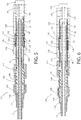
- FIG. 5 illustrates the fiber optic assembly 118 in an installed state (also referred to as a connected state) with the receptacle 126.
- the receptacle 126 may be a bulkhead or panel mounted receptacle, or a receptacle that is mounted to a circuit board.
- the receptacle 126 includes a housing 128 that forms a longitudinal passage 130 for receiving the terminus 10.
- the receptacle 126 houses an optical component 132 that optically interfaces with the fiber optic filament 14 of the fiber optic cable 12.
- the optical component 132 may be passive or may be active (e.g., an optical receiver, an optical transmitter, an optical transceiver, or another optical terminus).
- the ferrule 24 may be received in a ferrule 134 of the optical component 132. Interaction of the ferrule 134 and/or the optical component 132 with the ferrule 24 may compress the spring 32 so as to increase the forward force placed on the filament 14 to facilitate optical coupling of the filament 14 and optical component 132.
- the body 22 of the terminus 10 is retained in the receptacle 126 in a manner to minimize longitudinal movement of the terminus 10 relative to the receptacle 126 in at least the rearward direction. Radial movement of the terminus relative to the receptacle 126 also may be restricted by interaction of the terminus 10 and the receptacle 126. In one embodiment, the terminus 10 and receptacle 126 have respective key features that limit rotation of the terminus 10 relative to the receptacle 126.
- a spring clip 136 is secured in the longitudinal passage 130 in a position to surround the body 22 of the terminus 10.
- the spring clip 136 includes one or more inwardly-biased, deflectable fingers 138.
- the fingers 138 may be resilient in nature so that they return to a natural position relative to the receptacle 126 when not moved by another object, such as the body 22 or the sleeve 116.
- each finger 138 is configured to be urged radially outward by the terminus body 22 when the terminus 10 is inserted into the longitudinal passage 130 through an open end 140 opposite the optical component 132. This allows passage of the forward portion 124 of the body 22 until the shoulder 36 passes forward ends 142 of the fingers 138. At the point where the shoulder 36 passes the forward ends 142 of the fingers 138, the fingers 138 move radially inward so that the ends 142 engage the shoulder 36, thereby trapping the body 22 in the longitudinal passage 130 and preventing removal of the terminus 10 from the receptacle 126.
- the shoulder 36 serves as a stop to prevent the fiber optic terminus 10 from being removed from the receptacle 126.
- the spring clip 136 may be a c-shaped clip that snaps into a slot 144 in an inner wall of the housing 128 that defines the passage 130 to secure the spring clip in the passage 130.
- Each finger 138 may be considered a latching or retaining member that latches or locks the terminus 10 in the receptacle 126. Other retaining member configurations are possible that may be released from the terminus 10 by the removal member 102.
- the removal member 102 In the installed configuration of the terminus 10, the removal member 102 is located in its retracted position and maintained in this position by the spring 104 and damping forces due to friction between spring 104 and cover 112, and between standoff 108 and grip 114.
- a portion of the sleeve 116 may be present in the longitudinal passage 130 and interposed between the housing 128 and the rearward portion 120 of the body. In this position, however, the sleeve 116 does not interfere with operation of the spring clip 136 to retain the terminus 10 in the receptacle 126.
- the forward end 122 of the sleeve In the retracted position, the forward end 122 of the sleeve is located rearward of the fingers 138 to not influence the position of the forward ends 142 of the fingers 138 relative to the shoulder 36.
- removal of the terminus 10 from the receptacle 126 will be described. Removal involves use of the removal member 102 to defeat the locking mechanism of the receptacle. In one embodiment, installation of the terminus 10 does not involve use of the removal member 102 (other than possibly holding the removal member 102 in a rearward location relative to the terminus 10). Rather, during installation, forward force on the termini 10 may be applied by pushing the cover 112. If used in this manner, the overboot assembly 100 provides strain relief to the fiber optic cable 12 during insertion.
- the removal process includes advancing the removal member 102 in the forward direction against the bias of the spring 104.
- the removal member 102 is moved relative to the fiber optic cable 12, terminus 10 and the receptacle 126 a sufficient distance and with sufficient force to defeat the locking mechanism that retains the terminus 10 in the receptacle 126.
- the removal member 102 is moved forward a sufficient distance to unlatch the fingers 138 from the body 22 of the terminus 10 to allow rearward movement of the terminus 10 relative to the receptacle 126.
- the forward movement of the sleeve 116 advances the forward end 122 of the sleeve 116 between the fingers 138 and the rearward portion 120 of the body 22 of the terminus 10.
- the sleeve 116 is advanced so that the forward end 122 contacts or almost contacts the shoulder 36 to displace the fingers 138 and free the fingers 138 from contacting the body 22 as shown in FIG. 6 .
- the removal process is completed by holding the removal member 102 in the advanced position and rearwardly moving the cable 12, the terminus 10 and the overboot assembly 100 relative to the receptacle 126.
- friction between the ends 142 of fingers 138 and the sleeve 116 may be sufficient to hold the removal member 102 in place after it is advanced in position.
- the ends 142 may contact the forward portion 124 of the body 22 as shown in FIG. 7 .
- the fingers 138 will no longer prevent further rearward movement of the terminus 10 relative to the receptacle 126 since there are no stops on the forward portion 124 of the body 22 to engage the fingers 138. Therefore, once the shoulder 36 clears the ends 142 of the fingers 138, the terminus 10 is free to be completely removed from the receptacle 126.
- the removal member 102 is inherently constrained in its movement. Radial movement is limited by the captive arrangement of the fiber optic cable 12 extending through the removal member 102. Rearward movement is limited by the CRM 110 having a fixed relationship to the fiber optic cable 12 and functioning as a stop for the anchor 106 and removal member 102. Forward movement of the removal member 102 may be made, but is restricted by the mechanical limits of the spring 104 and/or the shoulder 36.
Landscapes
- Physics & Mathematics (AREA)
- General Physics & Mathematics (AREA)
- Optics & Photonics (AREA)
- Mechanical Coupling Of Light Guides (AREA)
Claims (11)
- Eine Überziehmuffenanordnung (100), die für eine faseroptische Anordnung (118) geeignet ist, die einen an einem faseroptischen Kabel (12) an einem Anschlussende desselben befestigten Endpunkt (10) aufweist, wobei der Endpunkt (10) so konfiguriert ist, dass er mit einer koordinierenden faseroptischen Buchse (126) zusammenpasst, und beim Zusammenstecken mit der faseroptischen Buchse wird der Endpunkt in der faseroptischen Buchse durch ein Endpunkthalteelement (138) gehalten, das sich in der faseroptischen Buchse (126) befindet und am Endpunkt (10) einrastet, wobei die Überziehmuffenanordnung (100) umfasst:einen Anker (106) mit einer in Längsrichtung fixierten Position relativ zu dem faseroptischen Kabel (12) und dem Endpunkt (10) in einem installierten Zustand, wobei sich die fixierte Position hinter dem Endpunkt (10) befindet;ein Entfernungselement (102), durch das das faseroptische Kabel (12) verläuft, wodurch das Entfernungselement (102) von der faseroptischen Anordnung nicht lösbar ist, wobei das Entfernungselement (102) in einer Vorwärtsrichtung relativ zum Anker (106) und somit dem faseroptische Kabel (12) und dem Endpunkt (10) in einem installierten Zustand vorschiebbar ist, um mit dem in der faseroptischen Aufnahme (126) angeordneten Endpunkthalteelement (138) zusammenzuwirken und in dieses einzugreifen und somit das Endpunkthalteelement (138) vom Endpunkt (10) zu entriegeln, so dass der Terminus lösbar und entfernbar aus der Buchse ist; undeine Feder (104), die das Entfernungselement (102) im eingebauten Zustand in eine zurückgezogene Position vorspannt, in der sich ein vorderes Ende des Entfernungselements hinter dem Endpunkthalteelement (138) befindet, um ein unbeabsichtigtes Lösen des Endpunkts (10) von der faseroptischen Buchse zu vermeiden;dadurch gekennzeichnet, dass die Feder (104) ein statisches hinteres Ende, das an dem Anker (106) befestigt ist und gegen diesen wirkt, und ein dynamisches vorderes Ende aufweist, das mit dem Entfernungselement (102) gekoppelt ist und auf dieses wirkt,wobei das Unlösbarmachen des Entfernungselements (102) von der faseroptischen Anordnung das Befestigen der Feder (104) und des Entfernungselements (102) umfasst.
- Die Überziehmuffenanordnung (100) nach Anspruch 1, die ferner ein Kabelhalteelement (110) aufweist, das an dem faseroptischen Kabel (12) befestigt ist, und wobei die feste Position des Ankers (106) durch Einklemmen des Ankers in Längsrichtung zwischen dem Kabelhalteelement (138) und dem Endpunkt (10) erreicht wird.
- Die Überziehmuffenanordnung (100) nach Anspruch 2, die ferner einen Abstandshalter (108) aufweist, wobei der Abstandshalter in Längsrichtung zwischen dem Anker (106) und dem Endpunkt (10) angeordnet ist.
- Die Überziehmuffenanordnung (100) nach einem der Ansprüche 1-3, wobei die Überziehmuffenanordnung (100) das Anschlussende des faseroptischen Kabels (12) an einer Verbindungsstelle desselben mit dem Endpunkt (10) strukturell abstützt, wobei die Abstützung eine Zugentlastung für die faseroptische Anordnung bereitstellt.
- Eine Faseroptische Anordnung (118), die die Überziehmuffenanordnung (100) nach Anspruch 1 umfasst, wobei die faseroptische Anordnung ferner umfasst:
ein Endpunkt (10), der an einem faseroptischen Kabel (12) an einem Anschlussende des faseroptischen Kabels befestigt ist, wobei der Endpunkt so konfiguriert ist, dass er mit einer koordinierenden faseroptischen Buchse (126) zusammenpasst, wobei der Endpunkt, wenn er mit der faseroptischen Buchse zusammengesetzt ist, in der faseroptischen Buchse durch ein Endpunkthalteelement (138) gehalten wird, das sich in der faseroptischen Buchse befindet und gegen den Endpunkt einrastet, umfassend:eine Presshülsenanordnung (24), die an einem faseroptischen Filament (14) des faseroptischen Kabels befestigt ist;einen Körper (22), der einen hinteren Abschnitt der Presshülsenanordnung umgibt und einen Abschnitt des Körpers hinter der Presshülsenanordnung, der in Längsrichtung in einer Position relativ zu dem faseroptischen Kabel befestigt ist; undeine zweite Feder (32), die radial zwischen dem hinteren Abschnitt der Presshülsenanordnung und dem Körper angeordnet ist, wobei die Feder gegen den Körper und die Presshülsenanordnung wirkt, um ein vorderes Ende des faseroptischen Filaments in eine Vorwärtsrichtung relativ zum Körper zu drängen. - Die faseroptische Anordnung nach Anspruch 5, wobei das Entfernungselement (12) das Endpunkthalteelement (138) von einer äußeren Schulter (36) des Körpers löst.
- Die faseroptische Anordnung nach einem der Ansprüche 5-6, wobei die Überziehmuffenanordnung (100) ferner ein Kabelhalteelement (110) aufweist, das an dem faseroptischen Kabel (12) befestigt ist, und wobei die feste Position des Ankers (106) dadurch erreicht wird, dass der Anker in Längsrichtung zwischen dem Kabelhalteelement (110) und dem Endpunkt (10) eingeklemmt wird.
- Die faseroptische Anordnung (118) nach Anspruch 7, wobei die Überziehmuffenanordnung (100) ferner einen Abstandshalter (108) aufweist, der in Längsrichtung zwischen dem Anker (106) und dem Endpunkt (10) angeordnet ist.
- Die faseroptische Anordnung (118) nach einem der Ansprüche 5-8, wobei die Überziehmuffenanordnung das Anschlussende des faseroptischen Kabels (12) an einer Verbindungsstelle desselben mit dem Endpunkt (10) strukturell abstützt, wobei die Abstützung eine Zugentlastung für die faseroptische Anordnung bereitstellt.
- Die Überziehmuffenanordnung (100) nach einem der Ansprüche 1-9, wobei eine Hülse (116) des Entfernungselements (102) das faseroptische Kabel (12) und einen hinteren Abschnitt (120) des Endpunkts (10) vollständig umgibt.
- Die Überziehmuffenanordnung (100) nach einem der Ansprüche 1-9, wobei eine Hülse (116) des Entfernungselements (102) das faseroptische Kabel (12) und einen rückwärtigen Abschnitt (120) des Endpunkts (10) teilweise umgibt und nicht von dem faseroptischen Kabel und dem Endpunkt trennbar ist.
Applications Claiming Priority (2)
| Application Number | Priority Date | Filing Date | Title |
|---|---|---|---|
| US201562130230P | 2015-03-09 | 2015-03-09 | |
| PCT/US2016/021408 WO2016144981A1 (en) | 2015-03-09 | 2016-03-08 | Overboot assembly for fiber optic cable terminus |
Publications (3)
| Publication Number | Publication Date |
|---|---|
| EP3268785A1 EP3268785A1 (de) | 2018-01-17 |
| EP3268785A4 EP3268785A4 (de) | 2018-08-01 |
| EP3268785B1 true EP3268785B1 (de) | 2020-11-18 |
Family
ID=56879652
Family Applications (1)
| Application Number | Title | Priority Date | Filing Date |
|---|---|---|---|
| EP16762360.2A Active EP3268785B1 (de) | 2015-03-09 | 2016-03-08 | Überziehmuffenanordnung für glasfaserkabelendstück |
Country Status (4)
| Country | Link |
|---|---|
| US (1) | US9678287B2 (de) |
| EP (1) | EP3268785B1 (de) |
| IL (1) | IL254543B (de) |
| WO (1) | WO2016144981A1 (de) |
Cited By (1)
| Publication number | Priority date | Publication date | Assignee | Title |
|---|---|---|---|---|
| EP4006604B1 (de) * | 2020-11-30 | 2025-04-16 | Corning Research & Development Corporation | Faseroptische adapteranordnung mit einem wandlergehäuse und einem freigabegehäuse |
Families Citing this family (3)
| Publication number | Priority date | Publication date | Assignee | Title |
|---|---|---|---|---|
| KR102868412B1 (ko) | 2020-01-03 | 2025-10-13 | 주식회사 쏠리드 | 광 모듈 어셈블리 |
| WO2021173793A1 (en) * | 2020-02-25 | 2021-09-02 | Senko Advanced Components, Inc. | Optical signal connector |
| CN119253357B (zh) * | 2024-12-05 | 2025-04-11 | 国网安徽省电力有限公司芜湖市繁昌区供电公司 | 一种应用于微电网的连接装置 |
Family Cites Families (15)
| Publication number | Priority date | Publication date | Assignee | Title |
|---|---|---|---|---|
| US4772081A (en) * | 1986-09-15 | 1988-09-20 | Tsi Incorporated | Fiber optic connector assembly |
| US5265182A (en) * | 1992-10-13 | 1993-11-23 | Hughes Aircraft Company | Retention and release mechanism for fiber optic alignment sleeve retainer |
| GB9307488D0 (en) * | 1993-04-08 | 1993-06-02 | Amp Holland | Optical fibre connector latching mechanism |
| US5661843A (en) * | 1996-01-30 | 1997-08-26 | Rifocs Corporation | Fiber optic probe |
| US5940559A (en) | 1996-07-17 | 1999-08-17 | Glenair, Inc. | Fiber-optic test probe and connector adapter for testing fiber-optic connector harnesses |
| US5778122A (en) * | 1996-12-24 | 1998-07-07 | Siecor Corporation | Fiber optic cable assembly for interconnecting optical fibers within a receptacle mounted within the wall of an enclosure |
| US5960137A (en) | 1997-09-12 | 1999-09-28 | Glenair, Inc. | Fiber-optic test probe and connector adapter for testing fiber-optic connector harnesses |
| US6625376B2 (en) * | 2001-02-09 | 2003-09-23 | Sci Systems, Inc. | Fiber-optic cable terminal connector and alignment device and method |
| US7244066B2 (en) * | 2005-02-25 | 2007-07-17 | Corning Cable Systems Llc | Fiber optic receptacle and plug assembly including alignment sleeve insert |
| US7264402B2 (en) * | 2005-03-10 | 2007-09-04 | Corning Cable Systems Llc | Multi-fiber optic receptacle and plug assembly |
| US7785019B2 (en) * | 2005-03-10 | 2010-08-31 | Corning Cable Systems Llc | Multi-fiber fiber optic receptacle and plug assembly |
| US7270562B1 (en) * | 2006-04-04 | 2007-09-18 | Tyco Electronics Corporation | Connector with thumb screw retention member |
| US7572065B2 (en) * | 2007-01-24 | 2009-08-11 | Adc Telecommunications, Inc. | Hardened fiber optic connector |
| JP5000778B2 (ja) * | 2010-09-06 | 2012-08-15 | 株式会社精工技研 | 光コネクタプラグ |
| US8858090B2 (en) * | 2012-06-05 | 2014-10-14 | Corning Cable Systems Llc | Ferrule holders with an integral lead-in tube employed in fiber optic connector assemblies, and related components, connectors, and methods |
-
2016
- 2016-03-08 US US15/064,580 patent/US9678287B2/en active Active
- 2016-03-08 EP EP16762360.2A patent/EP3268785B1/de active Active
- 2016-03-08 WO PCT/US2016/021408 patent/WO2016144981A1/en not_active Ceased
-
2017
- 2017-09-08 IL IL254543A patent/IL254543B/en active IP Right Grant
Non-Patent Citations (1)
| Title |
|---|
| None * |
Cited By (1)
| Publication number | Priority date | Publication date | Assignee | Title |
|---|---|---|---|---|
| EP4006604B1 (de) * | 2020-11-30 | 2025-04-16 | Corning Research & Development Corporation | Faseroptische adapteranordnung mit einem wandlergehäuse und einem freigabegehäuse |
Also Published As
| Publication number | Publication date |
|---|---|
| IL254543B (en) | 2018-04-30 |
| WO2016144981A1 (en) | 2016-09-15 |
| EP3268785A4 (de) | 2018-08-01 |
| US20160266329A1 (en) | 2016-09-15 |
| IL254543A0 (en) | 2017-10-31 |
| US9678287B2 (en) | 2017-06-13 |
| EP3268785A1 (de) | 2018-01-17 |
Similar Documents
| Publication | Publication Date | Title |
|---|---|---|
| CN109752803B (zh) | 多光纤推进式光纤连接器 | |
| AU2017228859B2 (en) | Ferrule-based fiber optic connectors with ferrule retraction balancing | |
| US7234877B2 (en) | Fiber optic industrial connector | |
| EP3622337B1 (de) | Steckbarer optischer steckverbinder mit verbinderintegriertem gelenk | |
| US9417407B2 (en) | Separable locking fiber optic connector | |
| US5661843A (en) | Fiber optic probe | |
| US9678287B2 (en) | Overboot assembly having unlatching and strain relief features for fiber optic cable terminus | |
| US9086546B2 (en) | Connector systems having receptacle assembly and plug assembly | |
| EP3304150B1 (de) | Faseroptischer abschlussadapter | |
| EP3830619B1 (de) | Glasfaserstecker mit halteelement | |
| JP7288438B2 (ja) | 光ファイバ端子コネクタ | |
| EP2914994B1 (de) | Terminusbaugruppe zum anklemmen an ein optisches kabel | |
| US9022667B2 (en) | Pin and socket terminus assemblies for terminating optical cables | |
| US20140126862A1 (en) | Terminus assembly for terminating an optical cable |
Legal Events
| Date | Code | Title | Description |
|---|---|---|---|
| STAA | Information on the status of an ep patent application or granted ep patent |
Free format text: STATUS: THE INTERNATIONAL PUBLICATION HAS BEEN MADE |
|
| PUAI | Public reference made under article 153(3) epc to a published international application that has entered the european phase |
Free format text: ORIGINAL CODE: 0009012 |
|
| STAA | Information on the status of an ep patent application or granted ep patent |
Free format text: STATUS: REQUEST FOR EXAMINATION WAS MADE |
|
| 17P | Request for examination filed |
Effective date: 20170926 |
|
| AK | Designated contracting states |
Kind code of ref document: A1 Designated state(s): AL AT BE BG CH CY CZ DE DK EE ES FI FR GB GR HR HU IE IS IT LI LT LU LV MC MK MT NL NO PL PT RO RS SE SI SK SM TR |
|
| AX | Request for extension of the european patent |
Extension state: BA ME |
|
| RIC1 | Information provided on ipc code assigned before grant |
Ipc: G02B 6/36 20060101AFI20180315BHEP Ipc: H01R 13/627 20060101ALI20180315BHEP Ipc: G02B 6/42 20060101ALI20180315BHEP Ipc: G02B 6/38 20060101ALI20180315BHEP |
|
| DAV | Request for validation of the european patent (deleted) | ||
| DAX | Request for extension of the european patent (deleted) | ||
| A4 | Supplementary search report drawn up and despatched |
Effective date: 20180704 |
|
| RIC1 | Information provided on ipc code assigned before grant |
Ipc: H01R 13/627 20060101ALI20180628BHEP Ipc: G02B 6/38 20060101ALI20180628BHEP Ipc: G02B 6/42 20060101ALI20180628BHEP Ipc: G02B 6/36 20060101AFI20180628BHEP |
|
| GRAP | Despatch of communication of intention to grant a patent |
Free format text: ORIGINAL CODE: EPIDOSNIGR1 |
|
| STAA | Information on the status of an ep patent application or granted ep patent |
Free format text: STATUS: GRANT OF PATENT IS INTENDED |
|
| INTG | Intention to grant announced |
Effective date: 20200619 |
|
| GRAS | Grant fee paid |
Free format text: ORIGINAL CODE: EPIDOSNIGR3 |
|
| GRAA | (expected) grant |
Free format text: ORIGINAL CODE: 0009210 |
|
| STAA | Information on the status of an ep patent application or granted ep patent |
Free format text: STATUS: THE PATENT HAS BEEN GRANTED |
|
| AK | Designated contracting states |
Kind code of ref document: B1 Designated state(s): AL AT BE BG CH CY CZ DE DK EE ES FI FR GB GR HR HU IE IS IT LI LT LU LV MC MK MT NL NO PL PT RO RS SE SI SK SM TR |
|
| REG | Reference to a national code |
Ref country code: GB Ref legal event code: FG4D |
|
| REG | Reference to a national code |
Ref country code: CH Ref legal event code: EP |
|
| REG | Reference to a national code |
Ref country code: IE Ref legal event code: FG4D |
|
| REG | Reference to a national code |
Ref country code: DE Ref legal event code: R096 Ref document number: 602016048115 Country of ref document: DE |
|
| REG | Reference to a national code |
Ref country code: AT Ref legal event code: REF Ref document number: 1336387 Country of ref document: AT Kind code of ref document: T Effective date: 20201215 |
|
| REG | Reference to a national code |
Ref country code: SE Ref legal event code: TRGR |
|
| REG | Reference to a national code |
Ref country code: AT Ref legal event code: MK05 Ref document number: 1336387 Country of ref document: AT Kind code of ref document: T Effective date: 20201118 |
|
| REG | Reference to a national code |
Ref country code: NL Ref legal event code: MP Effective date: 20201118 |
|
| PG25 | Lapsed in a contracting state [announced via postgrant information from national office to epo] |
Ref country code: NO Free format text: LAPSE BECAUSE OF FAILURE TO SUBMIT A TRANSLATION OF THE DESCRIPTION OR TO PAY THE FEE WITHIN THE PRESCRIBED TIME-LIMIT Effective date: 20210218 Ref country code: RS Free format text: LAPSE BECAUSE OF FAILURE TO SUBMIT A TRANSLATION OF THE DESCRIPTION OR TO PAY THE FEE WITHIN THE PRESCRIBED TIME-LIMIT Effective date: 20201118 Ref country code: PT Free format text: LAPSE BECAUSE OF FAILURE TO SUBMIT A TRANSLATION OF THE DESCRIPTION OR TO PAY THE FEE WITHIN THE PRESCRIBED TIME-LIMIT Effective date: 20210318 Ref country code: GR Free format text: LAPSE BECAUSE OF FAILURE TO SUBMIT A TRANSLATION OF THE DESCRIPTION OR TO PAY THE FEE WITHIN THE PRESCRIBED TIME-LIMIT Effective date: 20210219 Ref country code: FI Free format text: LAPSE BECAUSE OF FAILURE TO SUBMIT A TRANSLATION OF THE DESCRIPTION OR TO PAY THE FEE WITHIN THE PRESCRIBED TIME-LIMIT Effective date: 20201118 |
|
| PG25 | Lapsed in a contracting state [announced via postgrant information from national office to epo] |
Ref country code: AT Free format text: LAPSE BECAUSE OF FAILURE TO SUBMIT A TRANSLATION OF THE DESCRIPTION OR TO PAY THE FEE WITHIN THE PRESCRIBED TIME-LIMIT Effective date: 20201118 Ref country code: BG Free format text: LAPSE BECAUSE OF FAILURE TO SUBMIT A TRANSLATION OF THE DESCRIPTION OR TO PAY THE FEE WITHIN THE PRESCRIBED TIME-LIMIT Effective date: 20210218 Ref country code: PL Free format text: LAPSE BECAUSE OF FAILURE TO SUBMIT A TRANSLATION OF THE DESCRIPTION OR TO PAY THE FEE WITHIN THE PRESCRIBED TIME-LIMIT Effective date: 20201118 Ref country code: IS Free format text: LAPSE BECAUSE OF FAILURE TO SUBMIT A TRANSLATION OF THE DESCRIPTION OR TO PAY THE FEE WITHIN THE PRESCRIBED TIME-LIMIT Effective date: 20210318 Ref country code: LV Free format text: LAPSE BECAUSE OF FAILURE TO SUBMIT A TRANSLATION OF THE DESCRIPTION OR TO PAY THE FEE WITHIN THE PRESCRIBED TIME-LIMIT Effective date: 20201118 |
|
| REG | Reference to a national code |
Ref country code: LT Ref legal event code: MG9D |
|
| PG25 | Lapsed in a contracting state [announced via postgrant information from national office to epo] |
Ref country code: HR Free format text: LAPSE BECAUSE OF FAILURE TO SUBMIT A TRANSLATION OF THE DESCRIPTION OR TO PAY THE FEE WITHIN THE PRESCRIBED TIME-LIMIT Effective date: 20201118 |
|
| PG25 | Lapsed in a contracting state [announced via postgrant information from national office to epo] |
Ref country code: RO Free format text: LAPSE BECAUSE OF FAILURE TO SUBMIT A TRANSLATION OF THE DESCRIPTION OR TO PAY THE FEE WITHIN THE PRESCRIBED TIME-LIMIT Effective date: 20201118 Ref country code: SK Free format text: LAPSE BECAUSE OF FAILURE TO SUBMIT A TRANSLATION OF THE DESCRIPTION OR TO PAY THE FEE WITHIN THE PRESCRIBED TIME-LIMIT Effective date: 20201118 Ref country code: LT Free format text: LAPSE BECAUSE OF FAILURE TO SUBMIT A TRANSLATION OF THE DESCRIPTION OR TO PAY THE FEE WITHIN THE PRESCRIBED TIME-LIMIT Effective date: 20201118 Ref country code: SM Free format text: LAPSE BECAUSE OF FAILURE TO SUBMIT A TRANSLATION OF THE DESCRIPTION OR TO PAY THE FEE WITHIN THE PRESCRIBED TIME-LIMIT Effective date: 20201118 Ref country code: CZ Free format text: LAPSE BECAUSE OF FAILURE TO SUBMIT A TRANSLATION OF THE DESCRIPTION OR TO PAY THE FEE WITHIN THE PRESCRIBED TIME-LIMIT Effective date: 20201118 Ref country code: EE Free format text: LAPSE BECAUSE OF FAILURE TO SUBMIT A TRANSLATION OF THE DESCRIPTION OR TO PAY THE FEE WITHIN THE PRESCRIBED TIME-LIMIT Effective date: 20201118 |
|
| REG | Reference to a national code |
Ref country code: DE Ref legal event code: R097 Ref document number: 602016048115 Country of ref document: DE |
|
| PG25 | Lapsed in a contracting state [announced via postgrant information from national office to epo] |
Ref country code: DK Free format text: LAPSE BECAUSE OF FAILURE TO SUBMIT A TRANSLATION OF THE DESCRIPTION OR TO PAY THE FEE WITHIN THE PRESCRIBED TIME-LIMIT Effective date: 20201118 |
|
| PLBE | No opposition filed within time limit |
Free format text: ORIGINAL CODE: 0009261 |
|
| STAA | Information on the status of an ep patent application or granted ep patent |
Free format text: STATUS: NO OPPOSITION FILED WITHIN TIME LIMIT |
|
| 26N | No opposition filed |
Effective date: 20210819 |
|
| PG25 | Lapsed in a contracting state [announced via postgrant information from national office to epo] |
Ref country code: IT Free format text: LAPSE BECAUSE OF FAILURE TO SUBMIT A TRANSLATION OF THE DESCRIPTION OR TO PAY THE FEE WITHIN THE PRESCRIBED TIME-LIMIT Effective date: 20201118 Ref country code: AL Free format text: LAPSE BECAUSE OF FAILURE TO SUBMIT A TRANSLATION OF THE DESCRIPTION OR TO PAY THE FEE WITHIN THE PRESCRIBED TIME-LIMIT Effective date: 20201118 Ref country code: NL Free format text: LAPSE BECAUSE OF FAILURE TO SUBMIT A TRANSLATION OF THE DESCRIPTION OR TO PAY THE FEE WITHIN THE PRESCRIBED TIME-LIMIT Effective date: 20201118 Ref country code: MC Free format text: LAPSE BECAUSE OF FAILURE TO SUBMIT A TRANSLATION OF THE DESCRIPTION OR TO PAY THE FEE WITHIN THE PRESCRIBED TIME-LIMIT Effective date: 20201118 |
|
| REG | Reference to a national code |
Ref country code: CH Ref legal event code: PL |
|
| PG25 | Lapsed in a contracting state [announced via postgrant information from national office to epo] |
Ref country code: SI Free format text: LAPSE BECAUSE OF FAILURE TO SUBMIT A TRANSLATION OF THE DESCRIPTION OR TO PAY THE FEE WITHIN THE PRESCRIBED TIME-LIMIT Effective date: 20201118 |
|
| REG | Reference to a national code |
Ref country code: BE Ref legal event code: MM Effective date: 20210331 |
|
| PG25 | Lapsed in a contracting state [announced via postgrant information from national office to epo] |
Ref country code: IE Free format text: LAPSE BECAUSE OF NON-PAYMENT OF DUE FEES Effective date: 20210308 Ref country code: ES Free format text: LAPSE BECAUSE OF FAILURE TO SUBMIT A TRANSLATION OF THE DESCRIPTION OR TO PAY THE FEE WITHIN THE PRESCRIBED TIME-LIMIT Effective date: 20201118 Ref country code: CH Free format text: LAPSE BECAUSE OF NON-PAYMENT OF DUE FEES Effective date: 20210331 Ref country code: LI Free format text: LAPSE BECAUSE OF NON-PAYMENT OF DUE FEES Effective date: 20210331 Ref country code: LU Free format text: LAPSE BECAUSE OF NON-PAYMENT OF DUE FEES Effective date: 20210308 |
|
| REG | Reference to a national code |
Ref country code: DE Ref legal event code: R081 Ref document number: 602016048115 Country of ref document: DE Owner name: COTSWORKS, INC., HIGHLAND HEIGHTS, US Free format text: FORMER OWNER: COTSWORKS, LLC, HIGHLAND HEIGHTS, OH, US |
|
| PG25 | Lapsed in a contracting state [announced via postgrant information from national office to epo] |
Ref country code: IS Free format text: LAPSE BECAUSE OF FAILURE TO SUBMIT A TRANSLATION OF THE DESCRIPTION OR TO PAY THE FEE WITHIN THE PRESCRIBED TIME-LIMIT Effective date: 20210318 |
|
| PG25 | Lapsed in a contracting state [announced via postgrant information from national office to epo] |
Ref country code: BE Free format text: LAPSE BECAUSE OF NON-PAYMENT OF DUE FEES Effective date: 20210331 |
|
| PG25 | Lapsed in a contracting state [announced via postgrant information from national office to epo] |
Ref country code: CY Free format text: LAPSE BECAUSE OF FAILURE TO SUBMIT A TRANSLATION OF THE DESCRIPTION OR TO PAY THE FEE WITHIN THE PRESCRIBED TIME-LIMIT Effective date: 20201118 |
|
| PG25 | Lapsed in a contracting state [announced via postgrant information from national office to epo] |
Ref country code: HU Free format text: LAPSE BECAUSE OF FAILURE TO SUBMIT A TRANSLATION OF THE DESCRIPTION OR TO PAY THE FEE WITHIN THE PRESCRIBED TIME-LIMIT; INVALID AB INITIO Effective date: 20160308 |
|
| PG25 | Lapsed in a contracting state [announced via postgrant information from national office to epo] |
Ref country code: MK Free format text: LAPSE BECAUSE OF FAILURE TO SUBMIT A TRANSLATION OF THE DESCRIPTION OR TO PAY THE FEE WITHIN THE PRESCRIBED TIME-LIMIT Effective date: 20201118 |
|
| PG25 | Lapsed in a contracting state [announced via postgrant information from national office to epo] |
Ref country code: TR Free format text: LAPSE BECAUSE OF FAILURE TO SUBMIT A TRANSLATION OF THE DESCRIPTION OR TO PAY THE FEE WITHIN THE PRESCRIBED TIME-LIMIT Effective date: 20201118 |
|
| PG25 | Lapsed in a contracting state [announced via postgrant information from national office to epo] |
Ref country code: MT Free format text: LAPSE BECAUSE OF FAILURE TO SUBMIT A TRANSLATION OF THE DESCRIPTION OR TO PAY THE FEE WITHIN THE PRESCRIBED TIME-LIMIT Effective date: 20201118 |
|
| PGFP | Annual fee paid to national office [announced via postgrant information from national office to epo] |
Ref country code: SE Payment date: 20260327 Year of fee payment: 11 |
|
| PGFP | Annual fee paid to national office [announced via postgrant information from national office to epo] |
Ref country code: GB Payment date: 20260327 Year of fee payment: 11 |
|
| PGFP | Annual fee paid to national office [announced via postgrant information from national office to epo] |
Ref country code: DE Payment date: 20260327 Year of fee payment: 11 |
|
| PGFP | Annual fee paid to national office [announced via postgrant information from national office to epo] |
Ref country code: FR Payment date: 20260325 Year of fee payment: 11 |