EP3269221B1 - Landwirtschaftliche sämaschine mit streichelement - Google Patents
Landwirtschaftliche sämaschine mit streichelement Download PDFInfo
- Publication number
- EP3269221B1 EP3269221B1 EP17401071.0A EP17401071A EP3269221B1 EP 3269221 B1 EP3269221 B1 EP 3269221B1 EP 17401071 A EP17401071 A EP 17401071A EP 3269221 B1 EP3269221 B1 EP 3269221B1
- Authority
- EP
- European Patent Office
- Prior art keywords
- seed
- furrow
- travel
- firmer
- dispensing device
- Prior art date
- Legal status (The legal status is an assumption and is not a legal conclusion. Google has not performed a legal analysis and makes no representation as to the accuracy of the status listed.)
- Active
Links
Images

Classifications
-
- A—HUMAN NECESSITIES
- A01—AGRICULTURE; FORESTRY; ANIMAL HUSBANDRY; HUNTING; TRAPPING; FISHING
- A01C—PLANTING; SOWING; FERTILISING
- A01C5/00—Making or covering furrows or holes for sowing, planting or manuring
- A01C5/06—Machines for making or covering drills or furrows for sowing or planting
- A01C5/066—Devices for covering drills or furrows
- A01C5/068—Furrow packing devices, e.g. press wheels
-
- A—HUMAN NECESSITIES
- A01—AGRICULTURE; FORESTRY; ANIMAL HUSBANDRY; HUNTING; TRAPPING; FISHING
- A01C—PLANTING; SOWING; FERTILISING
- A01C5/00—Making or covering furrows or holes for sowing, planting or manuring
- A01C5/06—Machines for making or covering drills or furrows for sowing or planting
- A01C5/066—Devices for covering drills or furrows
Definitions
- the invention relates to an agricultural seed drill according to the preamble of patent claim 1.
- the seed drill has at least one furrow opening device to which a seed dispensing device is assigned.
- the seed delivery device deposits the seed in the open furrow.
- a brushing and / or pressing element closes the open furrow after the seed has been deposited and covers the furrow with earth.
- the seed dispensing device is assigned a brushing element which has a first upper, a second middle and a third lower area. With the first upper area, the brush element is attached to the rear side of the seed depositing device in the direction of travel.
- the second central area of the brush element is designed to be flexible and is suitably curved for guiding the seed.
- the third lower area of the brush element is convex towards the bottom of the seed furrow and consists of smooth, abrasion-resistant material.
- the brushing element protrudes backwards into the seed furrow as seen in the direction of travel. In the seed furrow, the brushing element brushes over the seed furrow base and seed deposited on it.
- the working pressure of the furrow opening device acts on the brush element with pressure against the seed furrow bottom in such a way that deposited seed is pressed into the seed furrow bottom to a suitable depth.
- a brush element designed in this way is exposed to great mechanical loads due to the pressure applied and the simultaneous movement of the sowing machine in the direction of travel. These typically cause the brushing element to lengthen and bend and thus cause permanent deformation over the course of its service life. There is a disadvantageous risk that the brush element can no longer reliably fulfill the intended function. At the same time, the elongated brushing element can get under the brushing and / or pressing device and be damaged.
- the invention is therefore based on the object of eliminating the disadvantages described and of providing a brushing element which ensures that the seed is guided into the seed furrow and / or the seed is pressed onto the seed furrow base and is insensitive to permanent deformation.
- the brush element is designed in the shape of a curve in the second central region and the curve points forward in the direction of travel and protrudes beyond the first upper region as seen in the direction of travel.
- the spreader element is attached with the front side of its first upper region in the direction of travel to the side of the seed dispensing device which is rearward in the direction of travel.
- the configuration according to the invention results in the advantage that the convexly curved side of the brush element points forward in the direction of travel to the seed depositing device.
- This configuration has surprisingly proven to be very dimensionally stable and insensitive to external forces.
- the trajectory of the seed dispensed by the seed dispenser is determined by the combination of its downward movement in the direction of the seed furrow and its movement in the direction of travel, determined by the forward speed of the seed drill in the direction of travel and an onset of drag-related braking when leaving the seed dispenser.
- the trajectory of the seed describes an arc that is convexly curved forwards in the direction of travel.
- the seed following the path curve described nestles against the convexly curved side of the brush element pointing forward in the direction of travel.
- the brushing element is used in an advantageous manner to guide the seeds released by the Saatgutabgabevor direction into the seed furrow.
- the brush element is at least approximately S-shaped.
- the curvature described is particularly easy to implement.
- a particular advantage is achieved in that the brushing element and the seed dispensing device are arranged with respect to one another in such a way that the seed dispensed by the seed dispensing device moves tangentially along the curvature of the brushing element.
- This is advantageous for a reliable guidance of the seed into the seed furrow by the grazing element, because the tangential guidance of the seeds along the curvature of the grazing element enables a smooth transfer of movement.
- the seeds hitting the grazing element can therefore not hit the grazing element.
- An impact against the strip element would reflect the seed and hinder reliable placement of the seed in the seed furrow.
- the first upper region of the brush element is designed to be rigid, in particular parallel to the direction of travel. A secure attachment of the grazing element to the seed depositing device is thus ensured.
- a rigid design of the first upper region reliably counteracts the length of the grazing element.
- the strip element can transfer the pressure onto the seed necessary for pressing the seed against the bottom of the seed furrow. If, on the other hand, the strip element is designed to be flexible in the first, upper area, it would be in the first area due to the application of pressure and the movement in the direction of travel Bend back the upper area, especially in the vicinity of the fastening elements.
- the first upper region of the brush element has an at least approximately T-shaped profile, with the central web pointing backwards in the direction of travel.
- the material thickness in this fastening area increases as a result, which is why, for example, tearing off is avoided.
- This configuration improves the security of the fastening of the grazing element on the seed depositing device.
- a T-shaped profile is suitable, due to its particularly high area moment of inertia, to considerably improve the flexural strength of the strip element.
- the T-shaped profile in the first, upper area is particularly advantageous so that there is no permanent bending of the strip element in the first upper area used for fastening.
- the T-shaped profile extends into the transition between the first, upper and the second, middle area of the strip element.
- This transition comprises the beginning of the arc of the grazing element which projects forward in the direction of travel beyond the first, upper area of the brushing element.
- the bending stiffness which is further increased by the T-shaped profile, prevents the strip element from lengthening.
- the first upper region of the brushing element has at least two knobs on the front side in the direction of travel, which are suitable for positive engagement in at least two recesses of the seed dispensing device.
- This configuration improves the security of the fastening considerably. For example, when cornering during the sowing operation, forces can occur on the grazing element transversely to the direction of travel. Such forces lead to tilting and / or twisting of the grazing element transversely to the direction of travel.
- the knobs according to the invention in this embodiment serve as a safety device, since they represent additional fixed points in addition to the fastening elements.
- An agricultural seed drill typically has a frame oriented transversely to the direction of travel F.
- fastening elements 1 several seed coulter units 2 are fastened to the frame, not shown, such as Fig. 1 shows.
- a coulter unit 2 has a support arm 3 which projects forward in the direction of travel F and which is connected to the fastening element 1.
- a groove opening element 4 is arranged on the support arm 3, which in the example of Figs. 1 to 3 is designed as a double disc coulter.
- the furrow opening element 4 has two coulter discs 5 which are set in a V-shape relative to one another and which are suitable for cutting into the ground and opening a furrow for depositing seeds.
- the coulter discs 5 are rotatably mounted on a holding element 6.
- the seed is deposited in the furrow by means of a seed dispensing device 7.
- the seed dispensing device 7 is fastened to the holding element 6 in the rear region of the coulter discs 5 in the direction of travel F, centered between the coulter discs 5 above the furrow.
- a pressure roller 8 following the furrow opening element 4 closes the opened furrow after the seed has been deposited.
- the pressure roller 8 is fastened to the support arm 3 via a holding arm 9.
- the pressed-on seed furrow is then covered with soil by means of a brushing element 10 connected to the holding arm 9.
- the seed dispensing device 7 releases the seed to be deposited into the seed furrow.
- the outlet opening 11 of the seed dispensing device 7 is at a distance of the order of centimeters from the ground and / or from the bottom of the seed furrow even during the sowing operation. The safe guidance of the seeds to be deposited is therefore guaranteed by a brush element 12.
- the brush element 12 is made of plastic and has a first upper area 13, a second central area 14 and a third lower area 15. In its first upper region 13, the brush element 12 is fastened to the rear side of the seed depositing device 7 in the direction of travel F by means of suitable fastening means 16. Screw connections and / or plug connections, for example, serve as fastening means 16. These are passed through a correspondingly provided recess 16A.
- the first upper area 13 of the brush element 12 has a T-shaped profile which considerably increases the flexural rigidity of the brush element in the first upper area, in particular along the direction of travel F, and prevents the brush element 12 from lengthening.
- the T-shaped profile preferably extends approximately to the transition between the first upper area 13 and the second central area 14.
- the central web of the T-shaped profile points in the direction of travel F to the rear.
- the brush element 12 is designed to be curved, in particular in the second central region 14 and its transitions to the first upper region 13 and the third lower region 15.
- the convex side of the arch 17 protrudes forward in the direction of travel F beyond the first upper region 13.
- the convex side of the arched rubbing element 12 points in the direction the seed furrow. This ensures that the seeds are guided from the outlet opening 11 of the seed dispensing element 7 into the seed furrow by means of the grazing element.
- the tangential movement prevents the seeds from bouncing off the grazing element.
- the arched shape of the brush element 12 prevents the brush element 12 from lengthening.
- the second central region 14 of the brush element 12 is designed to be flexible.
- the brush element 12 is thus protected from damage caused by overload.
- the strip element 12 is pretensioned against the ground.
- the third lower region 15 of the grazing element 12 points backwards in the direction of travel F and protrudes into the seed furrow. It has a convex shape opposite the seed furrow and consists of a smooth, wear-resistant material. Due to the flexible design of the central second area 14, it is pretensioned with respect to the furrow base and sweeps over the furrow base and the seed placed on it. The pre-tensioning causes the deposited seeds to be pressed against the bottom of the furrow. The smooth surface prevents the deposited seeds from being pushed together. This creates optimal germination conditions for the seeds. The abrasion resistance protects the material of the strip element 12 and increases its service life considerably.
- each of these coulter units 2 is equipped with a brush element 12 according to the invention.
Landscapes
- Life Sciences & Earth Sciences (AREA)
- Soil Sciences (AREA)
- Environmental Sciences (AREA)
- Sowing (AREA)
Description
- Die Erfindung betrifft eine landwirtschaftliche Sämaschine gemäß des Oberbegriffes des Patentanspruches 1.
- Eine derartige Sämaschine ist in
US 5 425 318 A beschrieben. Die Sämaschine weist zumindest eine Furchenöffnungsvorrichtung auf, der eine Saatgutabgabevorrichtung zugeordnet ist. Die Saatgutabgabevorrichtung legt das Saatgut in der geöffneten Furche ab. Ein Zustreich- und/oder Andrückelement schließt die geöffnete Furche nach der Saatgutablage und bedeckt die Furche mit Erde. Der Saatgutabgabevorrichtung ist ein Streichelement zugeordnet, welches einen ersten oberen, einen zweiten mittleren und einen dritten unteren Bereich aufweist. Mit dem ersten oberen Bereich ist das Streichelement auf der in Fahrtrichtung rückwärtigen Seite der Saatgutablagevorrichtung befestigt. Der zweite mittlere Bereich des Streichelements ist flexibel ausgebildet und zur Leitung des Saatguts geeignet gekrümmt. Der dritte untere Bereich des Streichelements ist zum Saatfurchengrund hin konvex geformt und besteht aus glattem, abriebfestem Material. Das Streichelement ragt in Fahrtrichtung gesehen nach hinten in die Saatfurche hinein. In der Saatfurche streicht das Streichelement über den Saatfurchengrund und auf diesem abgelegtes Saatgut. Gegen den Saatfurchengrund ist das Streichelement durch den Arbeitsdruck der Furchenöffnungsvorrichtung derart mit Druck beaufschlagt, dass abgelegtes Saatgut bis zu einer geeigneten Tiefe in den Saatfurchengrund gedrückt wird. - Während des Säbetriebes ist ein derartig ausgeführtes Streichelement aufgrund des beaufschlagten Drucks und der gleichzeitigen Bewegung der Sämaschine in Fahrtrichtung großen mechanischen Belastungen ausgesetzt. Diese bewirken typischerweise ein Längen und Verbiegen des Streichelements und somit im Laufe der Einsatzzeit eine dauerhafte Verformung. Es besteht dabei in nachteiliger Weise die Gefahr, dass das Streichelement die ihm angedachte Funktion nicht mehr zuverlässig erfüllen kann. Zugleich kann das gelängte Streichelement unter die Zustreich- und/oder Andrückvorrichtung geraten und beschädigt werden.
- Der Erfindung liegt daher die Aufgabe zugrunde, die beschriebenen Nachteile abzustellen und ein Streichelement bereitzustellen, welches die Saatgutführung in die Saatfurche und/oder das Andrücken des Saatguts auf dem Saatfurchengrund gewährleistet und unempfindlich gegen dauerhaftes Verformen ist.
- Die Aufgabe wird erfindungsgemäß dadurch gelöst, dass das Streichelement im zweiten mittleren Bereich bogenförmig ausgestaltet ist und der Bogen in Fahrtrichtung nach vorn weist und über den ersten oberen Bereich in Fahrtrichtung gesehen hinausragt.
- Das Streichelement ist mit der in Fahrtrichtung vorderen Seite seines ersten oberen Bereichs an der in Fahrtrichtung rückwärtigen Seite der Saatgutabgabevorrichtung befestigt. Durch die erfindungsgemäße Ausgestaltung ergibt sich dabei der Vorteil, dass die konvex gekrümmte Seite des Streichelements in Fahrtrichtung nach vorn zur Saatgutablagevorrichtung weist. Diese Ausgestaltung hat sich überraschender Weise als sehr formbeständig und unempfindlich gegen von außen einwirkende Kräfte erwiesen.
- Die Bahnkurve des von der Saatgutabgabevorrichtung abgegebenen Saatguts wird durch die Kombination ihrer Bewegung nach unten in Richtung der Saatfurche und ihrer Bewegung in Fahrtrichtung, festgelegt durch die Vortriebsgeschwindigkeit der Sämaschine in Fahrtrichtung und einer einsetzenden, luftwiderstandbedingten Bremswirkung bei Verlassen der Saatgutabgabevorrichtung, bestimmt. In dieser Kombination beschreibt die Bahnkurve des Saatguts einen in Fahrtrichtung nach vorn konvex gekrümmten Bogen.
- Durch die erfindungsgemäße Bogenform des Streichelements schmiegt sich das der beschriebenen Bahnkurve folgende Saatgut an die in Fahrtrichtung nach vorn weisende, konvex gekrümmte Seite des Streichelements an. Dadurch dient das Streichelement in vorteilhafter Weise der Führung des von der Saatgutabgabevor richtung abgegebenen Saatguts in die Saatfurche.
- Durch den in Fahrtrichtung über den ersten oberen Bereich des Streichelements hinausragenden Bogen des Streichelements ist das Streichelement im Übergang zwischen dem ersten oberen und dem zweiten mittleren Bereich in Richtung der Fahrtrichtung gekrümmt. Damit ist die Krümmung des Streichelements der entgegen der Fahrtrichtung gerichteten, das Längen verursachenden Kraftwirkung entgegengerichtet. Somit wird eine hohe Biegesteifigkeit des Streichelements in Fahrtrichtung der Sämaschine erreicht. Dadurch entsteht der Vorteil, dass die erfindungsgemäße Krümmung des Streichelements einem Längen entgegenwirkt. Dadurch wird die Lebensdauer des Streichelements erheblich erhöht.
- Es ist vorteilhaft, dass das Streichelement zumindest annähernd S-förmig ist. In dieser Ausgestaltung ist die beschriebene Krümmung besonders einfach umzusetzen.
- Es wird ein besonderer Vorteil dadurch erreicht, dass das Streichelement und die Saatgutabgabevorrichtung derart zueinander angeordnet sind, dass sich das von der Saatgutabgabevorrichtung abgegebene Saatgut tangential entlang der Krümmung des Streichelements bewegt. Dies ist für eine zuverlässige Führung des Saatguts in die Saatfurche durch das Streifelement vorteilhaft, weil durch die tangentiale Führung des Saatguts entlang der Krümmung des Streifelements eine sanfte Bewegungsübernahme ermöglicht wird. Das auf das Streifelement treffende Saatgut kann somit nicht gegen das Streifelement stoßen. Ein Stoßen gegen das Streifelement würde das Saatgut reflektieren und eine zuverlässige Ablage des Saatguts in der Saatfurche behindern.
- Es ist besonders vorteilhaft, dass der erste obere Bereich des Streichelements, insbesondere parallel zur Fahrtrichtung, biegesteif ausgeführt ist. Somit ist eine sichere Befestigung des Streifelements an der Saatgutablagevorrichtung sichergestellt. Zudem wirkt eine biegesteife Ausführung des ersten oberen Bereichs einem Längen des Streifelements zuverlässig entgegen. Überdies kann das Streifelement nur aufgrund einer Biegesteifigkeit im der Befestigung dienenden ersten, oberen Bereich den zum Andrücken des Saatguts an den Saatfurchengrund notwendigen Druck auf das Saatgut übertragen. Ist das Streifelement hingegen im ersten, oberen Bereich flexibel ausgestaltet, würde es sich aufgrund der Druckbeaufschlagung und der Bewegung in Fahrtrichtung bereits im ersten oberen Bereich, insbesondere in der Nähe der Befestigungselemente nach hinten verbiegen.
- Es ist vorteilhaft, dass der erste obere Bereich des Streichelements ein zumindest annähernd T-förmiges Profil, wobei der Mittelsteg in Fahrtrichtung nach hinten weist, aufweist. Die Materialstärke in diesem Befestigungsbereich steigt dadurch an, weswegen beispielweise ein Abreißen vermieden wird. Durch diese Ausgestaltung wird die Sicherheit der Befestigung des Streifelements an der Saatgutablagevorrichtung verbessert. Zudem ist ein T-förmiges Profil aufgrund seines besonders hohen Flächenträgheitsmoments geeignet, die Biegesteifigkeit des Streifelements erheblich zu verbessern. Damit kein dauerhaftes Verbiegen des Streifelements im der Befestigung dienenden ersten oberen Bereich auftritt, ist das T-förmige Profil im ersten, oberen besonders vorteilhaft.
- Es ist ebenfalls vorteilhaft, dass sich das T-förmige Profil bis in den Übergang zwischen dem ersten, oberen und dem zweiten, mittleren Bereich des Streifelements erstreckt. Dieser Übergang umfasst den Beginn des in Fahrtrichtung nach vorn über den ersten, oberen Bereich des Streichelements hinausragenden Bogens des Streifelements. Besonders im Zusammenwirken mit der beschriebenen Krümmung in diesem Bereich, verhindert die durch das T-förmige Profil weiter gesteigerte Biegesteifigkeit ein Längen des Streifelements.
- Es ist von Vorteil, dass der erste obere Bereich des Streichelements auf der in Fahrtrichtung vorderen Seite zumindest zwei Noppen aufweist, welche zum formschlüssigen Eingriff in zumindest zwei Aussparungen der Saatgutabgabevorrichtung geeignet sind. Diese Ausgestaltung verbessert die Sicherheit der Befestigung erheblich. Beispielsweise in Kurvenfahrten während des Säbetriebes können an das Streifelement Kräfte quer zur Fahrtrichtung auftreten. Derartige Kräfte führen zu einem Verkanten und/oder Verdrehen des Streifelements quer zur Fahrtrichtung. Um ein solches Verkanten und/oder Verdrehen zu vermeiden, dienen die erfindungsgemäßen Noppen dieser Ausführungsform als Sicherung, da sie ergänzend zu den Befestigungselementen zusätzliche Fixpunkte darstellen.
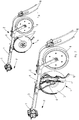
- Weitere Einzelheiten der Erfindung sind der Beispielsbeschreibung und den Zeichnungen zu entnehmen. Die Zeichnungen zeigen
- Fig.1
- eine Säschareinheit einer landwirtschaftlichen Sämaschine in perspektivischer Darstellung von schräg hinten,
- Fig.2
- eine geöffnete Säschareinheit einer landwirtschaftlichen Sämaschine in perspektivischer Ansicht von schräg hinten,
- Fig.3
- die Saatgutabgabevorrichtung mit Streichelement innerhalb der Säschareinheit in perspektivischer Ansicht von schräg hinten,
- Fig.4
- das Streichelement in seitlicher Ansicht und
- Fig.5
- das Streichelement in perspektivischer Ansicht von schräg hinten.
- Eine landwirtschaftliche Sämaschine weist typischerweise einen quer zur Fahrtrichtung F ausgerichteten Rahmen auf. Mittels Befestigungselementen 1 sind an dem nicht dargestellten Rahmen mehrere Säschareinheiten 2 befestigt, wie
Fig. 1 zeigt. - Eine Säschareinheit 2 weist einen in Fahrtrichtung F nach vorn ragenden Tragarm 3 auf, welcher mit dem Befestigungselement 1 verbunden ist. An dem Tragarm 3 ist ein Furchenöffnungselement 4 angeordnet, welches im Beispiel der
Fig. 1 bis 3 als Doppelscheibenschar ausgeführt ist. Das Furchenöffnungselement 4 weist zwei V-förmig zueinander angestellte Scharscheiben 5 auf, welche geeignet sind, in den Erdboden einzuschneiden und eine Furche zur Ablage von Saatgut zu öffnen. Die Scharscheiben 5 sind an einem Halteelement 6 drehbar gelagert. - Das Saatgut wird mittels einer Saatgutabgabevorrichtung 7 in der Furche abgelegt. Die Saatgutabgabevorrichtung 7 ist im in Fahrtrichtung F hinteren Bereich der Scharscheiben 5 zentriert zwischen den Scharscheiben 5 oberhalb der Furche an dem Halteelement 6 befestigt. Die zeigt die geöffnete Ansicht der Säschareinheit in
Fig. 2 . - Eine dem Furchenöffnungselement 4 nachlaufende Andruckrolle 8 schließt die geöffnete Furche nach der Saatgutsablage. Die Andruckrolle 8 ist über einen Haltearm 9 am Tragarm 3 befestigt. Die angedrückte Saatfurche wird anschließend mittels eines mit dem Haltearm 9 verbundenen Zustreichelements 10 mit Erde bedeckt.
- Während des Säbetriebes entlässt die Saatgutabgabevorrichtung 7 das abzulegende Saatgut in die Saatfurche. Die Auslassöffnung 11 der Saatgutabgabevorrichtung 7 weist aber auch während des Säbetriebes zum Erdboden und/oder zum Saatfurchengrund eine Entfernung in der Größenordnung von Zentimetern auf. Die sichere Führung des abzulegenden Saatguts wird daher von einem Streichelement 12 gewährleistet.
- Das Streichelement 12 ist aus Kunststoff gefertigt und weist einen ersten oberen Bereich 13, einen zweiten mittleren Bereich 14 und einen dritten unteren Bereich 15 auf. In seinem ersten oberen Bereich 13 ist das Streichelement 12 auf der in Fahrtrichtung F rückwärtigen Seite der Saatgutablagevorrichtung 7 mittels geeigneter Befestigungsmittel 16 befestigt. Als Befestigungsmittel 16 dienen beispielsweise Schraub- und/oder Steckverbindungen. Diese werden durch eine entsprechend vorgesehene Aussparung 16A geführt.
- Der erste obere Bereich 13 des Streichelements 12 weist ein T-förmiges Profil auf, welches die Biegesteifigkeit des Streichelements im ersten oberen Bereich insbesondere entlang der Fahrtrichtung F erheblich erhöht und ein Längen des Streichelements 12 verhindert. Das T-förmige Profil erstreckt sich vorzugsweise etwa bis zum Übergang zwischen dem ersten oberen Bereich 13 und dem zweiten mittleren Bereich 14. Der Mittelsteg des T-förmigen Profils weist in Fahrtrichtung F nach hinten.
- Das Streichelement 12 ist, insbesondere im zweiten mittleren Bereich 14 und dessen Übergängen zu dem ersten oberen Bereich 13 und dem dritten unteren Bereich 15 bogenförmig ausgeführt. Dabei ragt die konvexe Seite des Bogens 17 in Fahrtrichtung F nach vorn über den ersten oberen Bereich 13 hinaus.
- Die Form des Bogens 17 ermöglicht im Zusammenwirken mit der Anordnung von Saatgutabgabeelement 7 und dem Streifelement zueinander dem aus der Auslassöffnung 11 der Saatgutabgabevorrichtung 7 entlassenen Saatgut eine tangentiale Bewegung entlang der konvexen Seite des bogenförmigen Streifelements 12. Die konvexe Seite des bogenförmigen Streifelements 12 weist in Richtung der Saatfurche. Damit ist die Führung des Saatguts von der Auslassöffnung 11 des Saatgutabgabeelements 7 in die Saatfurche mittels des Streifelements gewährleistet. Durch die tangentiale Bewegung wird ein Abprallen des Saatguts vom Streifelement vermieden.
- Insbesondere im Zusammenwirken mit dem T-förmigen Profil des ersten oberen Bereichs 13 des verhindert die Bogenform des Streichelements 12 ein Längen des Streichelements 12.
- Der zweite mittlere Bereich 14 des Streichelements 12 ist flexibel ausgeführt. Somit ist das Streichelement 12 vor überlastbedingten Beschädigungen geschützt. Zudem wird eine Vorspannung des Streifelements 12 gegen den Erdboden erreicht.
- Der dritte untere Bereich 15 des Streifelements 12 weist in Fahrtrichtung F nach hinten und ragt in die Saatfurche hinein. Er ist gegenüber der Saatfurche konvex geformt und besteht aus einem glatten, abriebfesten Material. Gegenüber dem Furchengrund ist er aufgrund der flexiblen Ausführung des mittleren zweiten Bereichs 14 vorgespannt und streicht über den Furchengrund und darauf abgelegtes Saatgut. Die Vorspannung bewirkt ein Andrücken der abgelegten Saatkörner an den Furchengrund. Dabei verhindert die glatte Oberfläche ein Zusammenschieben der abgelegten Saatkörner. Dies schafft optimale Keimbedingungen für das Saatgut. Die Abriebfestigkeit schützt das Material des Streifelements 12 und erhöht dessen Lebensdauer erheblich.
- Bei Kurvenfahrten während des Säbetriebes wirken Querbelastungen auf das Streifelement 12. Damit sich dieses aufgrund dieser Querbelastungen nicht verkantet und/oder verdreht, ist es auf seiner zur Befestigung an der Saatgutabgabevorrichtung 7 vorgesehenen in Fahrtrichtung F vorderen Seite mit zwei Noppen 18 ausgestattet. Die Noppen 18 greifen formschlüssig in zwei dafür vorgesehene Aussparungen. Somit bilden die beiden Noppen 18 zusätzliche Fixpunkte im Bereich der Befestigung des Streifelements 12 an der Saatgutabgabevorrichtung 7, welche eine Sicherung gegen ein Verkanten und/oder Verdrehen darstellen.
- Weist eine Sämaschine mehrere der beschriebenen Säschareinheiten 2 aus, so ist jede dieser Säschareinheiten 2 mit einem erfindungsgemäßen Streichelement 12 ausgestattet.
Claims (6)
- Landwirtschaftliche Sämaschine aufweisend zumindest eine Furchenöffnungsvorrichtung (4), zumindest eine Saatgutabgabevorrichtung (7) zur Saatgutablage in die geöffnete Saatfurche, zumindest ein Zustreich- (10) und/oder Andrückelement zum Schließen der geöffneten Saatfurche, wobei der Saatgutabgabevorrichtung ein Streichelement (12), aufweisend einen ersten oberen, einen zweiten mittleren und einen dritten unteren Bereich (13, 14, 15), zugeordnet ist und das Streichelement in seinem ersten oberen Bereich (13) auf der in Fahrtrichtung (F) gesehen rückwärtigen Seite der Saatgutablagevorrichtung (7) befestigt ist, der zweite mittlere Bereich (14) des Streichelements flexibel ausgebildet und zur Leitung des Saatguts in die Saatfurche geeignet gekrümmt ist, der dritte untere Bereich (15) des Streichelements (12) zum Saatfurchengrund hin konvex geformt ist, aus glattem, abriebfestem Material besteht und in Fahrtrichtung gesehen nach hinten in die Saatfurche hineinragt, wobei das Streichelement in der Saatfurche über den Saatfurchengrund und abgelegtes Saatgut streicht und gegen den Saatfurchengrund durch den Arbeitsdruck der Furchenöffnungsvorrichtung (4) derart mit Druck beaufschlagt ist, dass abgelegtes Saatgut bis zu einer geeigneten Tiefe in den Saatfurchengrund gedrückt wird, wobei das Streichelement (12) im zweiten mittleren Bereich (14) bogenförmig ausgestaltet ist, dadurch gekennzeichnet, dass der Bogen in Fahrtrichtung (F) nach vorn weist und über den ersten oberen Bereich in Fahrtrichtung gesehen hinausragt.
- Sämaschine nach Anspruch 1, dadurch gekennzeichnet, dass das Streichelement zumindest annähernd S-förmig ist.
- Sämaschine nach zumindest einem der vorangegangenen Ansprüche, dadurch gekennzeichnet, dass das Streichelement und die Saatgutabgabevorrichtung derart zueinander angeordnet sind, dass sich das von der Saatgutabgabevorrichtung abgegebene Saatgut tangential entlang der Krümmung des Streichelements bewegt.
- Sämaschine nach zumindest einem der vorangegangenen Ansprüche, dadurch gekennzeichnet, dass der erste obere Bereich des Streichelements, insbesondere parallel zur Fahrtrichtung, biegesteif ausgeführt ist.
- Sämaschine nach zumindest einem der vorangegangenen Ansprüche, dadurch gekennzeichnet, dass der erste obere Bereich des Streichelements ein zumindest annähernd T-förmiges Profil, wobei der Mittelsteg in Fahrtrichtung nach hinten weist, aufweist.
- Sämaschine nach zumindest einem der vorangegangenen Ansprüche, dadurch gekennzeichnet, dass der erste obere Bereich des Streichelements auf der in Fahrtrichtung vorderen Seite zumindest zwei Noppen (18) aufweist, welche zum formschlüssigen Eingriff in zumindest zwei Aussparungen der Saatgutabgabevorrichtung (7) geeignet sind.
Priority Applications (1)
| Application Number | Priority Date | Filing Date | Title |
|---|---|---|---|
| PL17401071T PL3269221T3 (pl) | 2016-07-11 | 2017-07-05 | Siewnik rolniczy z elementem zgarniającym |
Applications Claiming Priority (1)
| Application Number | Priority Date | Filing Date | Title |
|---|---|---|---|
| DE102016112635.7A DE102016112635A1 (de) | 2016-07-11 | 2016-07-11 | Landwirtschaftliche Sämaschine mit Streichelelement |
Publications (2)
| Publication Number | Publication Date |
|---|---|
| EP3269221A1 EP3269221A1 (de) | 2018-01-17 |
| EP3269221B1 true EP3269221B1 (de) | 2020-11-11 |
Family
ID=59363081
Family Applications (1)
| Application Number | Title | Priority Date | Filing Date |
|---|---|---|---|
| EP17401071.0A Active EP3269221B1 (de) | 2016-07-11 | 2017-07-05 | Landwirtschaftliche sämaschine mit streichelement |
Country Status (3)
| Country | Link |
|---|---|
| EP (1) | EP3269221B1 (de) |
| DE (1) | DE102016112635A1 (de) |
| PL (1) | PL3269221T3 (de) |
Cited By (1)
| Publication number | Priority date | Publication date | Assignee | Title |
|---|---|---|---|---|
| US20230020374A1 (en) * | 2021-07-14 | 2023-01-19 | Botanic Gardens and Parks Authority | Apparatus for seeding |
Families Citing this family (4)
| Publication number | Priority date | Publication date | Assignee | Title |
|---|---|---|---|---|
| BR112022006689A2 (pt) | 2019-12-03 | 2022-07-12 | Prec Planting Llc | Guias de sementes para plantadores |
| DE102020113479A1 (de) * | 2020-05-19 | 2021-11-25 | Amazonen-Werke H. Dreyer SE & Co. KG | Sävorrichtung und landwirtschaftliche Sä- und/oder Düngermaschine |
| RU2758061C1 (ru) * | 2020-11-11 | 2021-10-26 | федеральное государственное бюджетное образовательное учреждение высшего образования "Ставропольский государственный аграрный университет" | Сошник |
| DE102024115597A1 (de) | 2024-06-05 | 2025-12-11 | Amazonen-Werke H. Dreyer SE & Co. KG | Reiheneinheit und Sämaschine zum Ablegen von Saatgut |
Family Cites Families (5)
| Publication number | Priority date | Publication date | Assignee | Title |
|---|---|---|---|---|
| DE280469C (de) * | ||||
| DE3441610A1 (de) * | 1984-08-10 | 1986-05-15 | Amazonen-Werke H. Dreyer Gmbh & Co Kg, 4507 Hasbergen | Drillmaschine |
| US5425318A (en) | 1994-02-14 | 1995-06-20 | J & K Keeton Enterprises, Inc. | Resilient seed firming attachment for a planting machine |
| US6666156B1 (en) * | 2002-08-22 | 2003-12-23 | New Holland North America | Seed flap for controlling seed placement |
| US7497174B2 (en) * | 2003-09-18 | 2009-03-03 | Precision Planting, Inc. | Planter bracket assembly for supporting appurtenances in substantial alignment with the seed tube |
-
2016
- 2016-07-11 DE DE102016112635.7A patent/DE102016112635A1/de not_active Withdrawn
-
2017
- 2017-07-05 PL PL17401071T patent/PL3269221T3/pl unknown
- 2017-07-05 EP EP17401071.0A patent/EP3269221B1/de active Active
Non-Patent Citations (1)
| Title |
|---|
| None * |
Cited By (2)
| Publication number | Priority date | Publication date | Assignee | Title |
|---|---|---|---|---|
| US20230020374A1 (en) * | 2021-07-14 | 2023-01-19 | Botanic Gardens and Parks Authority | Apparatus for seeding |
| US12178152B2 (en) * | 2021-07-14 | 2024-12-31 | The University Of Western Australia | Apparatus for seeding |
Also Published As
| Publication number | Publication date |
|---|---|
| EP3269221A1 (de) | 2018-01-17 |
| PL3269221T3 (pl) | 2021-05-17 |
| DE102016112635A1 (de) | 2018-01-11 |
Similar Documents
| Publication | Publication Date | Title |
|---|---|---|
| DE2319736C3 (de) | Abstreifvorrichtung für Gurtbänder | |
| EP3837934B1 (de) | Bodenbearbeitungsgerät zur landwirtschaftlichen aufbereitung von erdreich | |
| EP3269221A1 (de) | Landwirtschaftliche sämaschine mit streichelement | |
| EP1974596B1 (de) | Säscharanordnung | |
| DE60033634T3 (de) | Sävorrichtung | |
| EP3266293B1 (de) | Landwirtschaftliche sämaschine mit zustreich- und/oder andrückvorrichtung | |
| DE202016103692U1 (de) | Landwirtschaftliche Sämaschine mit Streichelement | |
| DE102016204433A1 (de) | Reiheneinheit einer landwirtschaftlichen Maschine | |
| DE69805207T2 (de) | Bodenbearbeitungsgerät mit stiel und spitze | |
| EP3254552B1 (de) | Säschar | |
| EP3225088B1 (de) | Bodenbearbeitungswerkzeug | |
| DE102006062328B3 (de) | Scheibenschar | |
| EP0295510B1 (de) | Bodenwalze | |
| DE2701982C3 (de) | Vereinzelungselement für pneumatische Einzelkornsämaschinen | |
| EP3269218B1 (de) | Landwirtschaftliche sämaschine mit abstreifelement | |
| WO2004078053A2 (de) | Sämaschine | |
| EP2335466B1 (de) | Sämaschine | |
| EP0170825B1 (de) | Vorsatzscharkörper | |
| EP3011813B1 (de) | Bodenbearbeitungsschar | |
| DE10227924B4 (de) | Silo-Austragvorrichtung | |
| DE29801820U1 (de) | Zweischeibenschar | |
| DE102023117303A1 (de) | Säscharanordnung | |
| EP2805595A1 (de) | Schar | |
| DE62571C (de) | Münzprüfer für Selbstverkäufer mit Reinigung der Münzenbahn und Prüfung nach Gewicht, Dicke, Durchmesser und Beschaffenheit der Prägungsfiäche der Münze | |
| EP4018799A1 (de) | Verfahren zum ablegen von granulatportionen auf eine landwirtschaftliche nutzfläche mittels einer landwirtschaftlichen ausbringmaschine |
Legal Events
| Date | Code | Title | Description |
|---|---|---|---|
| PUAI | Public reference made under article 153(3) epc to a published international application that has entered the european phase |
Free format text: ORIGINAL CODE: 0009012 |
|
| STAA | Information on the status of an ep patent application or granted ep patent |
Free format text: STATUS: THE APPLICATION HAS BEEN PUBLISHED |
|
| AK | Designated contracting states |
Kind code of ref document: A1 Designated state(s): AL AT BE BG CH CY CZ DE DK EE ES FI FR GB GR HR HU IE IS IT LI LT LU LV MC MK MT NL NO PL PT RO RS SE SI SK SM TR |
|
| AX | Request for extension of the european patent |
Extension state: BA ME |
|
| STAA | Information on the status of an ep patent application or granted ep patent |
Free format text: STATUS: REQUEST FOR EXAMINATION WAS MADE |
|
| 17P | Request for examination filed |
Effective date: 20180713 |
|
| RBV | Designated contracting states (corrected) |
Designated state(s): AL AT BE BG CH CY CZ DE DK EE ES FI FR GB GR HR HU IE IS IT LI LT LU LV MC MK MT NL NO PL PT RO RS SE SI SK SM TR |
|
| GRAP | Despatch of communication of intention to grant a patent |
Free format text: ORIGINAL CODE: EPIDOSNIGR1 |
|
| STAA | Information on the status of an ep patent application or granted ep patent |
Free format text: STATUS: GRANT OF PATENT IS INTENDED |
|
| INTG | Intention to grant announced |
Effective date: 20200730 |
|
| GRAS | Grant fee paid |
Free format text: ORIGINAL CODE: EPIDOSNIGR3 |
|
| GRAA | (expected) grant |
Free format text: ORIGINAL CODE: 0009210 |
|
| STAA | Information on the status of an ep patent application or granted ep patent |
Free format text: STATUS: THE PATENT HAS BEEN GRANTED |
|
| AK | Designated contracting states |
Kind code of ref document: B1 Designated state(s): AL AT BE BG CH CY CZ DE DK EE ES FI FR GB GR HR HU IE IS IT LI LT LU LV MC MK MT NL NO PL PT RO RS SE SI SK SM TR |
|
| REG | Reference to a national code |
Ref country code: GB Ref legal event code: FG4D Free format text: NOT ENGLISH |
|
| REG | Reference to a national code |
Ref country code: CH Ref legal event code: EP |
|
| REG | Reference to a national code |
Ref country code: AT Ref legal event code: REF Ref document number: 1332548 Country of ref document: AT Kind code of ref document: T Effective date: 20201115 |
|
| REG | Reference to a national code |
Ref country code: DE Ref legal event code: R096 Ref document number: 502017008144 Country of ref document: DE |
|
| REG | Reference to a national code |
Ref country code: IE Ref legal event code: FG4D Free format text: LANGUAGE OF EP DOCUMENT: GERMAN |
|
| REG | Reference to a national code |
Ref country code: SE Ref legal event code: TRGR |
|
| REG | Reference to a national code |
Ref country code: NL Ref legal event code: MP Effective date: 20201111 |
|
| RAP4 | Party data changed (patent owner data changed or rights of a patent transferred) |
Owner name: AMAZONEN-WERK H. DREYER SE & CO. KG |
|
| PG25 | Lapsed in a contracting state [announced via postgrant information from national office to epo] |
Ref country code: NO Free format text: LAPSE BECAUSE OF FAILURE TO SUBMIT A TRANSLATION OF THE DESCRIPTION OR TO PAY THE FEE WITHIN THE PRESCRIBED TIME-LIMIT Effective date: 20210211 Ref country code: PT Free format text: LAPSE BECAUSE OF FAILURE TO SUBMIT A TRANSLATION OF THE DESCRIPTION OR TO PAY THE FEE WITHIN THE PRESCRIBED TIME-LIMIT Effective date: 20210311 Ref country code: RS Free format text: LAPSE BECAUSE OF FAILURE TO SUBMIT A TRANSLATION OF THE DESCRIPTION OR TO PAY THE FEE WITHIN THE PRESCRIBED TIME-LIMIT Effective date: 20201111 Ref country code: FI Free format text: LAPSE BECAUSE OF FAILURE TO SUBMIT A TRANSLATION OF THE DESCRIPTION OR TO PAY THE FEE WITHIN THE PRESCRIBED TIME-LIMIT Effective date: 20201111 Ref country code: GR Free format text: LAPSE BECAUSE OF FAILURE TO SUBMIT A TRANSLATION OF THE DESCRIPTION OR TO PAY THE FEE WITHIN THE PRESCRIBED TIME-LIMIT Effective date: 20210212 |
|
| REG | Reference to a national code |
Ref country code: DE Ref legal event code: R081 Ref document number: 502017008144 Country of ref document: DE Owner name: AMAZONEN-WERKE H. DREYER SE & CO. KG, DE Free format text: FORMER OWNER: AMAZONEN-WERKE H.DREYER GMBH & CO.KG, 49205 HASBERGEN, DE |
|
| RAP4 | Party data changed (patent owner data changed or rights of a patent transferred) |
Owner name: AMAZONEN-WERKE H. DREYER SE & CO. KG |
|
| PG25 | Lapsed in a contracting state [announced via postgrant information from national office to epo] |
Ref country code: BG Free format text: LAPSE BECAUSE OF FAILURE TO SUBMIT A TRANSLATION OF THE DESCRIPTION OR TO PAY THE FEE WITHIN THE PRESCRIBED TIME-LIMIT Effective date: 20210211 Ref country code: LV Free format text: LAPSE BECAUSE OF FAILURE TO SUBMIT A TRANSLATION OF THE DESCRIPTION OR TO PAY THE FEE WITHIN THE PRESCRIBED TIME-LIMIT Effective date: 20201111 Ref country code: IS Free format text: LAPSE BECAUSE OF FAILURE TO SUBMIT A TRANSLATION OF THE DESCRIPTION OR TO PAY THE FEE WITHIN THE PRESCRIBED TIME-LIMIT Effective date: 20210311 |
|
| REG | Reference to a national code |
Ref country code: LT Ref legal event code: MG9D |
|
| PG25 | Lapsed in a contracting state [announced via postgrant information from national office to epo] |
Ref country code: HR Free format text: LAPSE BECAUSE OF FAILURE TO SUBMIT A TRANSLATION OF THE DESCRIPTION OR TO PAY THE FEE WITHIN THE PRESCRIBED TIME-LIMIT Effective date: 20201111 |
|
| PG25 | Lapsed in a contracting state [announced via postgrant information from national office to epo] |
Ref country code: SM Free format text: LAPSE BECAUSE OF FAILURE TO SUBMIT A TRANSLATION OF THE DESCRIPTION OR TO PAY THE FEE WITHIN THE PRESCRIBED TIME-LIMIT Effective date: 20201111 Ref country code: SK Free format text: LAPSE BECAUSE OF FAILURE TO SUBMIT A TRANSLATION OF THE DESCRIPTION OR TO PAY THE FEE WITHIN THE PRESCRIBED TIME-LIMIT Effective date: 20201111 Ref country code: RO Free format text: LAPSE BECAUSE OF FAILURE TO SUBMIT A TRANSLATION OF THE DESCRIPTION OR TO PAY THE FEE WITHIN THE PRESCRIBED TIME-LIMIT Effective date: 20201111 Ref country code: EE Free format text: LAPSE BECAUSE OF FAILURE TO SUBMIT A TRANSLATION OF THE DESCRIPTION OR TO PAY THE FEE WITHIN THE PRESCRIBED TIME-LIMIT Effective date: 20201111 Ref country code: LT Free format text: LAPSE BECAUSE OF FAILURE TO SUBMIT A TRANSLATION OF THE DESCRIPTION OR TO PAY THE FEE WITHIN THE PRESCRIBED TIME-LIMIT Effective date: 20201111 |
|
| REG | Reference to a national code |
Ref country code: DE Ref legal event code: R097 Ref document number: 502017008144 Country of ref document: DE |
|
| PG25 | Lapsed in a contracting state [announced via postgrant information from national office to epo] |
Ref country code: DK Free format text: LAPSE BECAUSE OF FAILURE TO SUBMIT A TRANSLATION OF THE DESCRIPTION OR TO PAY THE FEE WITHIN THE PRESCRIBED TIME-LIMIT Effective date: 20201111 |
|
| PLBE | No opposition filed within time limit |
Free format text: ORIGINAL CODE: 0009261 |
|
| STAA | Information on the status of an ep patent application or granted ep patent |
Free format text: STATUS: NO OPPOSITION FILED WITHIN TIME LIMIT |
|
| 26N | No opposition filed |
Effective date: 20210812 |
|
| PG25 | Lapsed in a contracting state [announced via postgrant information from national office to epo] |
Ref country code: AL Free format text: LAPSE BECAUSE OF FAILURE TO SUBMIT A TRANSLATION OF THE DESCRIPTION OR TO PAY THE FEE WITHIN THE PRESCRIBED TIME-LIMIT Effective date: 20201111 Ref country code: NL Free format text: LAPSE BECAUSE OF FAILURE TO SUBMIT A TRANSLATION OF THE DESCRIPTION OR TO PAY THE FEE WITHIN THE PRESCRIBED TIME-LIMIT Effective date: 20201111 |
|
| PG25 | Lapsed in a contracting state [announced via postgrant information from national office to epo] |
Ref country code: SI Free format text: LAPSE BECAUSE OF FAILURE TO SUBMIT A TRANSLATION OF THE DESCRIPTION OR TO PAY THE FEE WITHIN THE PRESCRIBED TIME-LIMIT Effective date: 20201111 |
|
| PG25 | Lapsed in a contracting state [announced via postgrant information from national office to epo] |
Ref country code: ES Free format text: LAPSE BECAUSE OF FAILURE TO SUBMIT A TRANSLATION OF THE DESCRIPTION OR TO PAY THE FEE WITHIN THE PRESCRIBED TIME-LIMIT Effective date: 20201111 |
|
| REG | Reference to a national code |
Ref country code: CH Ref legal event code: PL |
|
| GBPC | Gb: european patent ceased through non-payment of renewal fee |
Effective date: 20210705 |
|
| PG25 | Lapsed in a contracting state [announced via postgrant information from national office to epo] |
Ref country code: MC Free format text: LAPSE BECAUSE OF FAILURE TO SUBMIT A TRANSLATION OF THE DESCRIPTION OR TO PAY THE FEE WITHIN THE PRESCRIBED TIME-LIMIT Effective date: 20201111 |
|
| REG | Reference to a national code |
Ref country code: BE Ref legal event code: MM Effective date: 20210731 |
|
| PG25 | Lapsed in a contracting state [announced via postgrant information from national office to epo] |
Ref country code: LI Free format text: LAPSE BECAUSE OF NON-PAYMENT OF DUE FEES Effective date: 20210731 Ref country code: GB Free format text: LAPSE BECAUSE OF NON-PAYMENT OF DUE FEES Effective date: 20210705 Ref country code: CH Free format text: LAPSE BECAUSE OF NON-PAYMENT OF DUE FEES Effective date: 20210731 |
|
| PG25 | Lapsed in a contracting state [announced via postgrant information from national office to epo] |
Ref country code: IS Free format text: LAPSE BECAUSE OF FAILURE TO SUBMIT A TRANSLATION OF THE DESCRIPTION OR TO PAY THE FEE WITHIN THE PRESCRIBED TIME-LIMIT Effective date: 20210311 Ref country code: LU Free format text: LAPSE BECAUSE OF NON-PAYMENT OF DUE FEES Effective date: 20210705 |
|
| PG25 | Lapsed in a contracting state [announced via postgrant information from national office to epo] |
Ref country code: IE Free format text: LAPSE BECAUSE OF NON-PAYMENT OF DUE FEES Effective date: 20210705 Ref country code: BE Free format text: LAPSE BECAUSE OF NON-PAYMENT OF DUE FEES Effective date: 20210731 |
|
| PG25 | Lapsed in a contracting state [announced via postgrant information from national office to epo] |
Ref country code: HU Free format text: LAPSE BECAUSE OF FAILURE TO SUBMIT A TRANSLATION OF THE DESCRIPTION OR TO PAY THE FEE WITHIN THE PRESCRIBED TIME-LIMIT; INVALID AB INITIO Effective date: 20170705 |
|
| P01 | Opt-out of the competence of the unified patent court (upc) registered |
Effective date: 20230523 |
|
| PG25 | Lapsed in a contracting state [announced via postgrant information from national office to epo] |
Ref country code: CY Free format text: LAPSE BECAUSE OF FAILURE TO SUBMIT A TRANSLATION OF THE DESCRIPTION OR TO PAY THE FEE WITHIN THE PRESCRIBED TIME-LIMIT Effective date: 20201111 |
|
| PG25 | Lapsed in a contracting state [announced via postgrant information from national office to epo] |
Ref country code: MK Free format text: LAPSE BECAUSE OF FAILURE TO SUBMIT A TRANSLATION OF THE DESCRIPTION OR TO PAY THE FEE WITHIN THE PRESCRIBED TIME-LIMIT Effective date: 20201111 |
|
| PG25 | Lapsed in a contracting state [announced via postgrant information from national office to epo] |
Ref country code: TR Free format text: LAPSE BECAUSE OF FAILURE TO SUBMIT A TRANSLATION OF THE DESCRIPTION OR TO PAY THE FEE WITHIN THE PRESCRIBED TIME-LIMIT Effective date: 20201111 |
|
| PG25 | Lapsed in a contracting state [announced via postgrant information from national office to epo] |
Ref country code: MT Free format text: LAPSE BECAUSE OF FAILURE TO SUBMIT A TRANSLATION OF THE DESCRIPTION OR TO PAY THE FEE WITHIN THE PRESCRIBED TIME-LIMIT Effective date: 20201111 |
|
| PGFP | Annual fee paid to national office [announced via postgrant information from national office to epo] |
Ref country code: PL Payment date: 20250612 Year of fee payment: 9 |
|
| PGFP | Annual fee paid to national office [announced via postgrant information from national office to epo] |
Ref country code: FR Payment date: 20250610 Year of fee payment: 9 |
|
| PGFP | Annual fee paid to national office [announced via postgrant information from national office to epo] |
Ref country code: CZ Payment date: 20250618 Year of fee payment: 9 |
|
| PGFP | Annual fee paid to national office [announced via postgrant information from national office to epo] |
Ref country code: SE Payment date: 20250610 Year of fee payment: 9 |
|
| PGFP | Annual fee paid to national office [announced via postgrant information from national office to epo] |
Ref country code: DE Payment date: 20250604 Year of fee payment: 9 |
|
| PGFP | Annual fee paid to national office [announced via postgrant information from national office to epo] |
Ref country code: IT Payment date: 20250623 Year of fee payment: 9 |
|
| PGFP | Annual fee paid to national office [announced via postgrant information from national office to epo] |
Ref country code: AT Payment date: 20250625 Year of fee payment: 9 |