EP3269285B1 - Reinigungstuch und reinigungsinstrument - Google Patents
Reinigungstuch und reinigungsinstrument Download PDFInfo
- Publication number
- EP3269285B1 EP3269285B1 EP15884633.7A EP15884633A EP3269285B1 EP 3269285 B1 EP3269285 B1 EP 3269285B1 EP 15884633 A EP15884633 A EP 15884633A EP 3269285 B1 EP3269285 B1 EP 3269285B1
- Authority
- EP
- European Patent Office
- Prior art keywords
- sheet
- cleaning
- nonwoven fabric
- strip
- fiber bundle
- Prior art date
- Legal status (The legal status is an assumption and is not a legal conclusion. Google has not performed a legal analysis and makes no representation as to the accuracy of the status listed.)
- Active
Links
Images


Classifications
-
- A—HUMAN NECESSITIES
- A47—FURNITURE; DOMESTIC ARTICLES OR APPLIANCES; COFFEE MILLS; SPICE MILLS; SUCTION CLEANERS IN GENERAL
- A47L—DOMESTIC WASHING OR CLEANING; SUCTION CLEANERS IN GENERAL
- A47L13/00—Implements for cleaning floors, carpets, furniture, walls, or wall coverings
- A47L13/10—Scrubbing; Scouring; Cleaning; Polishing
- A47L13/16—Cloths; Pads; Sponges
-
- A—HUMAN NECESSITIES
- A47—FURNITURE; DOMESTIC ARTICLES OR APPLIANCES; COFFEE MILLS; SPICE MILLS; SUCTION CLEANERS IN GENERAL
- A47L—DOMESTIC WASHING OR CLEANING; SUCTION CLEANERS IN GENERAL
- A47L13/00—Implements for cleaning floors, carpets, furniture, walls, or wall coverings
- A47L13/10—Scrubbing; Scouring; Cleaning; Polishing
- A47L13/38—Other dusting implements
-
- A—HUMAN NECESSITIES
- A47—FURNITURE; DOMESTIC ARTICLES OR APPLIANCES; COFFEE MILLS; SPICE MILLS; SUCTION CLEANERS IN GENERAL
- A47L—DOMESTIC WASHING OR CLEANING; SUCTION CLEANERS IN GENERAL
- A47L13/00—Implements for cleaning floors, carpets, furniture, walls, or wall coverings
- A47L13/10—Scrubbing; Scouring; Cleaning; Polishing
- A47L13/42—Details
- A47L13/44—Securing scouring-cloths to the brush or like body of the implement
Definitions
- the present invention relates to a cleaning sheet and a cleaning tool for cleaning an object to be cleaned.
- JP-A No. 2014-150963 discloses a cleaning sheet configured to be attached to a holder.
- a cleaning operation is performed by using a cleaning side sheet having strips and a fiber assembly. Further, in the cleaning operation, the strips and constituent fibers of the fiber assembly are raised, so that a space for capturing dust is provided between the strips and the constituent fibers of the fiber assembly. Specifically, by providing the space for capturing dust in a region of the cleaning sheet which is actually used for cleaning operation, the cleaning sheet has an effective cleaning function.
- Patent Document 1 JP-A No. 2014-150963 . Further prior art in this technical filed is disclosed in documents US 2014/183780 A1 , WO 02/03847A2 , GB 2414286 A , EP 1967119 A2 and WO 2014/123012 A1 .
- a cleaning sheet according to the present invention is defined by the combination of features according to claim 1, wherein the cleaning sheet is configured to be attached to a holder and has a holding region which is attached to the holder and a cleaning region which comes in contact with an object to be cleaned.
- the holding region has sheet elements and a receiving part configured to receive the holder and formed by superposing the sheet elements.
- the receiving part is configured to be removably attached to the holder.
- the cleaning region has a fiber bundle, a cleaning side sheet-like member superposed on the fiber bundle, and a bonding part that bonds the fiber bundle and the cleaning side sheet-like member.
- the fiber bundle is formed by arranging a plurality of fiber bundle constituent fibers having prescribed orientation.
- the cleaning side sheet-like member has a first surface facing the fiber bundle, a second surface on the side opposite to the first surface, a cut element and a strip element defined by the cut element
- the cut element consists of a plurality of cuts.
- the strip element is formed between adjacent ones of the cuts and has a first strip and a second strip. Further, the strip element has a plurality of strips, and any pair of the strips can be respectively defined as the first strip and the second strip.
- the fiber bundle constituent fibers are configured to be bent along the bonding part so as to be raised up in a direction away from the holding region.
- Each of the first strip and the second strip has a first engagement part formed on the first surface and a second engagement part formed on the second surface and is configured to be bent along the bonding part so as to be raised up in a direction away from the holding region.
- a space for capturing dust is formed between the fiber bundle constituent fibers and the first and second strips.
- a user can raise the fiber bundle constituent fibers and the first and second strips by holding both ends of the cleaning sheet with both hands and alternately moving the hands up and down, or by shaking the user's hand holding the holder attached to the cleaning sheet.
- the first engagement part can be engaged with the fiber bundle constituent fibers and the second engagement part of the first strip and the second engagement part of the second strip can be engaged with each other.
- the cleaning sheet according to this invention is raised, while the first engagement parts of the strips are engaged with the fiber bundle constituent fibers and the first and second strips are engaged with each other via the respective second engagement parts. Therefore, particularly in an early stage of a cleaning operation, the raised state of the strips and the fiber bundle constituent fibers can be easily maintained.
- engagement or "engage” as used in the present invention is explained.
- the cleaning side sheet-like member is a nonwoven fabric
- the cleaning side sheet-like member has nonwoven fabric constituent fibers forming the nonwoven fabric. Therefore, the engagement between the first strip and the second strip means that the nonwoven fabric constituent fibers of the first and second strips are entangled with each other.
- the "engagement" between the strips and the fiber bundle constituent fibers means that the nonwoven fabric constituent fibers of the strips and the fiber bundle constituent fibers are entangled with each other.
- the cleaning side sheet-like member has a first direction which is defined by a direction from the bonding part toward a free end of the strip element, and a second direction crossing the first direction.
- the cleaning side sheet-like member may be formed of nonwoven fabric.
- the nonwoven fabric may have a plurality of nonwoven fabric constituent fibers having orientation in the first direction.
- the first engagement part may be formed of the nonwoven fabric constituent fibers exposed to the first surface.
- the nonwoven fabric constituent fibers and the fiber bundle constituent fibers can be engaged with each other.
- the second engagement part may be formed of the nonwoven fabric constituent fibers exposed to the second surface.
- the nonwoven fabric constituent fibers of the first strip and the nonwoven fabric constituent fibers of the second strip can be engaged with each other.
- the nonwoven fabric preferably has higher rigidity in the first direction than in the second direction.
- the nonwoven fabric has rigidity of 69.7 mm to 80.0 mm in the first direction and rigidity of 35.0 mm to 39.9 mm in the second direction.
- the nonwoven fabric preferably has total light transmittance of 83.03 to 88.43 %.
- the nonwoven fabric has a larger average surface friction coefficient in the first direction on the second surface than on the first surface.
- the nonwoven fabric preferably has an average surface friction coefficient of 0.126 to 0.129 ⁇ in the first direction on the first surface and an average surface friction coefficient of 0.138 to 0.145 ⁇ in the first direction on the second surface.
- the nonwoven fabric preferably has a larger average surface friction coefficient in the second direction on the second surface than on the first surface.
- the nonwoven fabric preferably has an average surface friction coefficient of 0.136 to 0.137 ⁇ in the second direction on the first surface and an average surface friction coefficient of 0.145 to 0.163 ⁇ in the second direction on the second surface.
- the nonwoven fabric preferably has a larger average deviation of surface roughness in the first direction on the second surface than on the first surface.
- the nonwoven fabric preferably has an average deviation of surface roughness of 3.225 to 3.350 ⁇ in the first direction on the first surface and an average deviation of surface roughness of 3.250 to 3.535 ⁇ in the first direction on the second surface.
- the sheet element may be a laminate sheet formed by superposing a first sheet-like member and a second sheet-like member one on the other.
- the laminate sheet has a first sheet bonding part which bonds the first and second sheet-like members, and a second sheet bonding part which is spaced apart from the first sheet bonding part and bonds the first and second sheet-like members.
- the receiving part may be defined by a space surrounded by the first sheet-like member, the second sheet-like member, the first sheet bonding part and the second sheet bonding part.
- the sheet element may be a single sheet-like member.
- the sheet-like member has a superposed part formed by superposing regions spaced apart from each other in the sheet-like member one on the other, and a sheet bonding part which bonds the superposed regions of the sheet-like member in the superposed part.
- the receiving part may be defined by a space surrounded by the sheet bonding part and a region of the sheet-like member which extends in a loop between the spaced-apait regions bonded at the sheet bonding part.
- a cleaning tool which has a holder and a cleaning sheet attached to the holder.
- the holder has a grip configured to be held by a user, and a long part connected to the grip.
- the cleaning sheet has a holding region attached to the long part and a cleaning region which comes in contact with an object to be cleaned.
- the holding region has sheet elements and a receiving part configured to receive the holder and formed by superposing the sheet elements.
- the receiving part is configured to be removably attached to the holder.
- the cleaning region has a fiber bundle, a cleaning side sheet-like member superposed on the fiber bundle, and a bonding part that bonds the fiber bundle and the cleaning side sheet-like member.
- the fiber bundle is formed by arranging a plurality of fiber bundle constituent fibers having prescribed orientation.
- the cleaning side sheet-like member has a first surface facing the fiber bundle, a second surface on the side opposite to the first surface, a cut element and a strip element defined by the cut element.
- the cut element consists of a plurality of cuts.
- the strip element is formed between adjacent ones of the cuts and has a first strip and a second strip. Further, the strip element has a plurality of strips, and any pair of the strips can be respectively defined as the first strip and the second strip.
- the fiber bundle constituent fibers are configured to be bent along the bonding part so as to be raised up in a direction away from the holding region.
- Each of the first and second strips has a first engagement part formed on the first surface and a second engagement part formed on the second surface and is configured to be bent along the bonding part so as to be raised up in a direction away from the holding region.
- a space for capturing dust is formed between the fiber bundle constituent fibers and the first and second strips.
- a user can raise the fiber bundle constituent fibers and the first and second strips by holding both, ends of the cleaning sheet with both hands and alternately moving the hands up and down, or by shaking the user's hand holding the holder attached to the cleaning sheet.
- the first engagement part can be engaged with the fiber bundle constituent fibers and the second engagement part of the first strip and the second engagement part of the second strip can be engaged with each other.
- the cleaning sheet is raised, while the first engagement parts of the strips are engaged with the fiber bundle constituent fibers and the first and second strips are engaged with each other via the respective second engagement parts. Therefore, particularly in an early stage of a cleaning operation, the raised state of the strips and the fiber bundle constituent fibers can be easily maintained.
- FIG. 1 is a perspective view showing a cleaning tool A100.
- the cleaning tool A100 includes a holder C100 and a cleaning sheet B100 which is removably attached to the holder C100.
- the cleaning sheet B100 has a holding region B110 to which the holder C100 is attached. Further, a region of the cleaning sheet B100 which comes in contact with an object to be cleaned forms a cleaning region B120.
- the cleaning tool A100, the holder C100, the cleaning sheet B100, the holding region B110 and the cleaning region B120 are example embodiments that correspond to the "cleaning tool”, the "holder”, the “cleaning sheet”, the “holding region” and the “cleaning region”, respectively, according to the present invention.
- the cleaning sheet B100 may be sold alone or sold as the cleaning tool A100 in a package in which the cleaning sheet B100 and the holder C100 are packed together.
- the cleaning sheet B100 may be of disposable type designed for single use, or disposable type designed for multiple use which can be used several times, while holding dust or dirt collected from a cleaning surface to be cleaned.
- the cleaning sheet B100 defines a prescribed cleaning sheet first direction B100y and a cleaning sheet second direction B100x crossing the cleaning sheet first direction B100y.
- a longitudinal direction of the cleaning sheet B100 coincides with the cleaning sheet first direction B100y.
- the holding region B110 extends in the cleaning sheet first direction B100y. Further, in the cleaning sheet first direction B100y, a direction in which the holder C100 is attached to the cleaning sheet B100 defines an inserting direction B100y1 and a direction in which the holder C100 is removed from the cleaning sheet B100 defines a removing direction B100y2.
- An extending direction of the holder C100 is defined by an extending direction of the cleaning sheet B100 when the holder C100 is attached to the cleaning sheet B100. Specifically, a long part C110 of the holder C100 is inserted into a receiving part B600 of the cleaning sheet B100 and extends in the cleaning sheet first direction B100y. Further detailed structures of the cleaning sheet B100 and the holder C100 are described below.
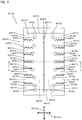
- FIG. 2 is a plan view showing the entire holder C100.
- the holder C100 has the long part C110 which is attached to the holding region B110 of the cleaning sheet B100, and a handle C160 configured to be held by a user.
- the long part C110 has a front end part C120, a base part C130 and an extending part C140 extending between the front end part C120 and the base part C130.
- the extending part C140 has a bifurcated form extending from the base part C130. It means that the long part C110 has the single base part C130 and has two extending parts C140 and two front end parts C120.
- the handle C160 has a front end part C161, a rear end part C162 and a grip C163 extending between the front end part C161 and the rear end part C162.
- the base part C130 of the long part C110 and the front end part C161 of the handle C160 are configured to be removable from each other.
- the long part C110 and the grip C163 are example embodiments that correspond to the "long part" and the "grip", respectively, according to the present invention.
- the holder C100 is formed of resin material.
- FIG. 3 is a plan view showing the cleaning sheet B100
- FIG. 4 is a bottom view showing the cleaning sheet B100
- FIG. 5 is a sectional view taken along line II-II in FIG. 3 .
- the cleaning sheet B100 mainly includes a sheet-like member and a fiber bundle B400.
- the sheet-like member refers to a first sheet B210, a second sheet B220 and a third sheet B230. Particularly the first sheet B210 and the second sheet B220 form a sheet element for forming the receiving part B600.
- the first sheet B210 and the second sheet B220 are an example embodiment that corresponds to the "sheet element" according to the present invention.
- the first sheet B210 and the second sheet B220 are superposed one on the other.
- the fiber bundle B400 is disposed between the second sheet B220 and the third sheet B230.
- the first sheet B210, the second sheet B220, the fiber bundle B400 and the third sheet B230 are bonded together by a first bonding part B710. Further, the first sheet B210, the second sheet B220 and part of the fiber bundle B400 are bonded together by a second bonding part B720.
- the holding region B110 is formed in a region surrounded by the second bonding part B720 between the first sheet B210 and the second sheet B220. In this sense, it can be said that the first bonding part B710 forms a dividing part for dividing the holding region B110.
- the first bonding part B710 is an example embodiment that corresponds to the "bonding part" according to the present invention.
- a laminate sheet formed by superposing the first and second sheets B210, B220 one on the other is bonded by a pair of second bonding parts B720.
- the second bonding parts B720 are arranged apart from each other.
- the pair second bonding parts B720 are example embodiments that correspond to the "first sheet bonding part” and the "second sheet bonding part” according to the present invention.
- the receiving part B600 is defined by a space surrounded by the first sheet B210, the second sheet B220 and the pair second bonding parts B720.
- the receiving part B600, the first sheet B210 and the second sheet B220 are example embodiments that correspond to the "receiving part", the "first sheet-like member” and the “second sheet-like member”, respectively, according to the present invention. Further, the receiving part B600 is divided by the first bonding part B710.
- the cleaning region B120 includes both end regions of the first sheet B210 and the second sheet B220 in the cleaning sheet first direction B100y, both end regions of the first sheet B210 and the second sheet B220 in the cleaning sheet second direction B100x, the fiber bundle B400 and the third sheet B230.
- the fiber bundle B400 and the third sheet B230 form a brush part B500 which is held in contact with a region to be cleaned by a user during cleaning operation.
- the third sheet B230 and the fiber bundle B400 are example embodiments that correspond to the "cleaning side sheet-like member" and the "fiber bundle", respectively, according to the present invention.
- the cleaning sheet B100 according to the first embodiment has the brush part B500 only on the second sheet B220 side.
- the brush part B500 may be formed on both sides of the receiving part B600 by bonding the fiber bundle B400 on both the first sheet B210 side and the second sheet B220 side.
- the receiving part B600 has openings B610 on its both ends.
- the long part C110 of the holder C100 can be inserted from either of the openings B610.
- the first sheet B210 is formed to be shorter than the second sheet B220 in the cleaning sheet first direction B100y.
- the first and second sheets B210, B220 have a plurality of cuts B331 extending in the cleaning sheet second direction B100x.
- the third sheet B230 also has a plurality of cuts B331 extending in the cleaning sheet second direction B100x.
- Strips B310 are formed between the adjacent cuts B331 in the first, second and third sheets B210, B220, B230. The strips B310 are brought in contact with the object to be cleaned by the user so as to perform a function of scraping dust.
- each of the first, second and third sheets B210, B220, B230 has a cut element B330 and a strip element B300 defined by the cut element B330.
- the cut element B330 consists of a plurality of the cuts B331 and the strip element B300 is formed between adjacent ones of the cuts B331.
- the strip element B300 consists of a plurality of the strips B310.
- the cut element B330, the strip element B300 and the cut B331 are example embodiments that correspond to the "cut element", the "strip element” and the “cut”, respectively, according to the present invention.
- the first, second and third sheets B210, B220, B230 are formed of flexible nonwoven fabric or other similar materials.
- the first, second and third sheets B210, B220, B230 which are welded by the bonding parts B710, B720 are preferably formed of nonwoven fabric of thermal melting fibers (thermoplastic fibers).
- thermal melting fibers thermoplastic fibers
- the first and second sheets B210, B220 may be formed of any material having a sufficient strength for use, such as nonwoven fabric, resin film and cloth containing synthetic fibers. Particularly, in terms of the strength, through-air nonwoven fabric is preferably used which has a basis weight of 10 to 100 gsm and is formed of conjugated fibers having a core of polyethylene terephthalate and a sheath of polyethylene.
- the third sheet B230 may be formed of any material having a sufficient strength for use, such as nonwoven fabric, resin film and cloth containing synthetic fibers.
- the third sheet B230 is formed of nonwoven fabric, particularly in terms of the strength, through-air nonwoven fabric is preferably used which has a basis weight of under 30 gsm and is formed of conjugated fibers having a core of polyethylene terephthalate and a sheath of polyethylene.
- the third sheet B230 is preferably formed to have a lighter basis weight than the first and second sheets B210, B220.
- the third sheet B230 can be formed to be lighter and more flexible than the first and second sheets B210, B220.
- the strips B310 of the third sheet B230 can be satisfactorily raised.
- FIG. 6 is an explanatory view showing the strip element B300 and
- FIG. 7 is an explanatory view showing the strip element and the fiber bundle.
- the third sheet B230 has a strip first direction B310y which is defined by a direction from the first bonding part B710 toward a free end of the strip element B300, and a strip second direction B310x crossing the strip first direction B310y.
- the strip first direction B310y and the strip second direction B310x are example embodiments that correspond to the "first direction" and the "second direction", respectively, according to the present invention.
- the strip B310 has a connected end B310b on the first bonding part B710 side and a free end B310a on the side opposite to the connected end B310b in the strip first direction B310y.
- a pair of the strips B310 which are opposed to each other on the opposite sides of the first bonding part B710 are defined as a first strip B321 and a second strip B322, respectively.
- the first strip B321 and the second strip B322 are example embodiments that correspond to the "first strip” and the "second strip", respectively, according to the present invention.
- nonwoven fabric constituent fibers B231 When the third sheet B230 is formed of nonwoven fabric, fibers forming the nonwoven fabric are referred to as nonwoven fabric constituent fibers B231.
- the nonwoven fabric constituent fiber B231 is an example embodiment that corresponds to the "nonwoven fabric constituent fiber" according to the present invention.
- the nonwoven fabric constituent fibers B231 are shown only in FIG. 7 for convenience of explanation.
- the nonwoven fabric constituent fibers B231 are arranged to have orientation in the strip first direction B310y.
- a plurality of fiber bundle constituent fibers B410 having prescribed orientation are arranged to form the fiber bundle B400. More specifically, the fiber bundle constituent fibers B410 have orientation in the strip first direction B310y. Further, as described below, the strips B310 and the fiber bundle constituent fibers B410 are deformed by cleaning operation. Therefore, the state in which the fiber bundle constituent fibers B410 have orientation in the strip first direction B310y refers to the state in which the strips B310 and the fiber bundle constituent fibers B410 are not yet moved or deformed, or the state of the fiber bundle constituent fibers B410 in design.
- the fiber bundle constituent fiber B410 is an example embodiment that corresponds to the "fiber bundle constituent fiber" according to the present invention.
- the fiber bundle constituent fiber B410 has a connected end B410b on the first bonding part B710 side and a free end B410a on the side opposite to the connected end B410b.
- the fiber bundle constituent fiber B410 represents a structure formed of "fibers".
- the "fibers” include a typical single fiber, and typical fibers aligned in the length direction and/or the radial direction (twist yarn, spun yarn, yarn to which a plurality of filaments are partially connected).
- the "typical fibers” as used herein are components of yarn, textile or the like and thin and flexible fibers having a substantially longer length compared with the thickness. Specifically, a long continuous fiber is defined as a filament and a short fiber as a staple. With this structure, the fiber bundle constituent fibers B410 have flexibility.
- the fiber bundle B400 is an assembly of the fiber bundle constituent fibers B410 which are manufactured from polyethylene, polypropylene, polyethylene terephthalate, nylon, rayon or the like.
- a so-called tow can be used as the fiber bundle constituent fibers B410.
- the fiber bundle constituent fibers B410 have a fineness of 0.5 to 66 dtex and are crimped fibers having 5 to 30 crimps per inch.
- the fiber bundle constituent fibers B410 are conjugated fibers having a core of polyethylene terephthalate and a core covering sheath of polyethylene.
- liquid paraffin is applied to the fiber bundle B400.
- the third sheet B230 has a first surface B311 facing the fiber bundle B400 and a second surface B312 on the side opposite to the first surface B311.
- the first surface B311 and the second surface B312 are example embodiments that correspond to the "first surface” and the "second surface", respectively, according to the present invention.
- the fiber bundle constituent fibers B410 and the strips B310 are flexible. Therefore, the fiber bundle constituent fibers B410 and the strips B310 are configured to be bent along the first bonding part B710 so as to be raised up in a direction away from the holding region B110.
- the strips B310 each have a first engagement part B311a formed on the first surface B311 and a second engagement part B312a formed on the second surface B312.
- the first engagement part B311a and the second engagement part B312a are example embodiments that correspond to the "first engagement part” and the "second engagement part", respectively, according to the present invention.
- the first engagement part B311a is formed by the nonwoven fabric constituent fibers B231 exposed to the first surface B311, and the second engagement part B312a is formed by the nonwoven fabric constituent fibers B231 exposed to the second surface B312.
- the cleaning tool A100 In use of the cleaning tool A100, a user raises the ships B310 and the fiber bundle constituent fibers B410 of the cleaning sheet B100. For this purpose, for example, the user holds both ends of the cleaning sheet B100 in the cleaning sheet first direction B100y with both hands and alternately moves the ends up and down, and thereafter attaches the holder CI00 to the cleaning sheet B100.
- the cleaning sheet B100 can also be raised by shaking up and down the user's hand holding the grip C163 of the holder C100 attached to the cleaning sheet B100.
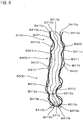
- FIG. 8 shows the raised state of the strips B310 and the fiber bundle constituent fibers B410. Further, for the sake of explanation, only the first strip B321, the second strip B322 and part of the fiber bundle constituent fibers B410 are shown in FIG. 8 .
- the first engagement part B311a is engaged with the fiber bundle constituent fibers B410.
- the first engagement part B311a and the fiber bundle constituent fibers B410 are required only to be partially engaged with each other, but not to be wholly engaged with each other.
- the second engagement part B312a of the first strip B321 and the second engagement part B312a of the second strip B322 are engaged with each other.
- the second engagement parts B312a of the two strips B310 are required only to be partially engaged with each other, but not to be wholly engaged with each other.
- the strips B310 and the fiber bundle constituent fibers B410 when the strips B310 and the fiber bundle constituent fibers B410 are raised, the strips B310 and the fiber bundle constituent fibers B410 are engaged with each other and the strips B310 are engaged with each other. Therefore, the strips B310 and the fiber bundle constituent fibers B410 which form the brush part B500 can be efficiently raised. As a result, particularly in an early stage of a cleaning operation, a space for capturing dust can be suitably secured between the strips B310 and the fiber bundle constituent fibers B410. Further, the volume of the brush part B500 is increased in appearance, which can provide the user with higher expectations for efficient cleaning operation.
- a preferable structure of the nonwoven fabric forming the third sheet B230 includes the following physical properties in order to raise the strips B310 and the fiber bundle constituent fibers B410 as described above. Further, the nonwoven fabric constituent fibers B231 preferably have orientation in the strip first direction B310y.
- the nonwoven fabric has low rigidity.
- the third sheet B230 is preferably formed of nonwoven fabric having rigidity of 69.7 to 80.0 mm in the first direction and rigidity of 35.0 to 39.9 mm in the second direction. Further, the rigidity is measured according to JIS L 8.21 bending resistance (cantilever A method). Thus, it is preferred that the third sheet B230 has higher rigidity in the first direction than in the second direction.
- first and second engagement parts B311a, B312a it is necessary to appropriately arrange the nonwoven fabric constituent fibers B231 on the first and second surfaces B311, B312.
- This structure can be achieved by increasing the distance between the nonwoven fabric constituent fibers B231 adjacent to each other. This increase means that the total light transmittance of the nonwoven fabric increases.
- the total light transmittance of the third sheet B230 is preferably 80% or more. More specifically, it is preferred that the third sheet B230 is formed of nonwoven fabric having a total light transmittance of 83.03 to 88.43%. Further, the total light transmittance is measured in accordance with JIS-K7105. More specifically, it was measured by a color difference meter Z-300A of light irradiation photometric system of Nippon Denshoku Industries Co., Ltd. domiciled at 4-45-17 Sengoku, Bunkyo-ku, Tokyo, Japan.
- the average friction coefficient of the second surface B312 in the strip first direction B310y is larger than that of the first surface B311 in the strip second direction B310x.
- the strips B310 can be engaged with each other in a satisfactory manner.
- the fiber bundle constituent fibers B410 engage with the strips B310 which are engaged with each other in a satisfactory manner, so that the reliability of raising the strips B310 and the fiber bundle constituent fibers B410 is improved.
- an average surface friction coefficient of the second surface B312 in the strip second direction B310x is larger than that of the first surface B311 in the strip second direction B310x.
- the third sheet B230 is preferably formed of nonwoven fabric having an average surface friction coefficient of 0.126 to 0.129 ⁇ in the strip first direction B310y on the first surface B311 and an average surface friction coefficient of 0.138 to 0.145 ⁇ in the strip first direction B310y on the second surface B312.
- the third sheet B230 is preferably formed of nonwoven fabric having an average surface friction coefficient of 0.136 to 0.137 ⁇ in the strip second direction B310x on the first surface B311 and an average surface friction coefficient of 0.145 to 0.163 ⁇ in the strip second direction B310x on the second surface B312.
- the average surface friction coefficient was evaluated by using KES-FB4 of Kato Tech Co., Ltd. domiciled at 26 Karato-cho, Nishikujo, Minami-ku, Kyoto, Japan. The measurement was conducted on a sample of nonwoven fabric having a size of 100 mm x 100 mm under a tension of 400 g, a friction static load of 50 g and a roughness static load of 10 g at a standard speed of 1 mm per second.
- the third sheet B230 has a rough surface.
- the third sheet B230 is a nonwoven fabric having an average deviation of surface roughness of 3.225 to 3.350 ⁇ in the strip first direction B310y on the first surface B311 and having an average deviation of surface roughness of 3.250 to 3.535 ⁇ in the strip first direction B310y on the second surface B312.
- the third sheet B230 is configured such that the average deviation of surface roughness in the strip first direction B310y on the second surface B312 is larger than that on the first surface B311.
- the average deviation of surface roughness was evaluated by using KES-FB4 of Kato Tech Co., Ltd.. The measurement was conducted on a sample of nonwoven fabric having a size of 100 mm x 100 mm under a tension of 400 g, a friction static load of 50 g and a roughness static load of 10 g at a standard speed of 1 mm per second.
- the cleaning sheet B100 having the following cleaning region B120 was prepared.
- the strips and the fiber bundle constituent fibers were raised under the same conditions and then the results were visually checked. As a result, it was confirmed that the cleaning sheet B100 in the example can be more satisfactorily raised than the cleaning sheet in the comparative example.
- the size of the third sheet B230 corresponding to seven strip sheets arranged in the strip second direction B310x was set to 40 mm square.
- the nonwoven fabrics of the example and the comparative example were prepared in such a manner as to meet the above-described conditions, and the thicknesses of the nonwoven fabrics were measured.
- the measurement was conducted by using a PEACOCK measuring instrument of Ozaki Mfg. Co., Ltd. domiciled at 1-63-11 Tokiwadai, Itabashi-ku, Tokyo, Japan.
- the PEACOCK measuring instrument has a measuring surface having a diameter of 44 mm and the measuring pressure is 3 g/cm 2 .
- the nonwoven fabric of the example has a thickness of 0.315 mm and the nonwoven fabric of the comparative example has a thickness of 0.6052 mm.
- the nonwoven fabric of the example is preferably thinner than the nonwoven fabric of the comparative example. Further, the basis weight of the nonwoven fabric of the example is lower than that of the nonwoven fabric of the comparative example, so that it is confirmed that a thinner and lighter nonwoven fabric is suitable to obtain an excellent raised state of the strips B310.
- a cleaning tool A100 according to a second embodiment of the present invention is now explained with reference to FIG. 9 .
- components or elements having the same structures and functions as those in the cleaning tool A100 of the first embodiment are given like numerals as in the first embodiment, and they are not described here.
- the cleaning tool A100 of the second embodiment is different from the cleaning tool A100 of the first embodiment in the structure of the holding region B110. Specifically, in the cleaning tool A100 of the second embodiment, the receiving part B600 is formed only by the first sheet B210.
- the first sheet B210 is an example embodiment that corresponds to the "single sheet-like member" according to the present invention.
- the first sheet B210 has a superposed part formed by superposing regions spaced apart from each other in the first sheet B210 one on the other.
- the superposed regions of the first sheet B210 are bonded by a bonding part B730 in the superposed part.
- the bonding part B730 is an example embodiment that corresponds to the "sheet bonding part" according to the present invention.
- the receiving part B600 is defined by a space surrounded by the bonding part B730 and a region of the first sheet B210 which extends in a loop between the spaced-apart regions bonded at the bonding part B730.
- the extending part C140 of the holder C100 can be attached to the receiving part B600.
- the cleaning region B120 has the same structure as that of the first embodiment, so that the same effect as the first embodiment can be obtained in raising the strips B310 and the fiber bundle constituent fibers B410.
- the cleaning tool A100 is an example embodiment that corresponds to the "cleaning tool” according to the present invention.
- the holder C100 is an example embodiment that corresponds to the "holder” according to the present invention.
- the cleaning sheet B100 is an example embodiment that corresponds to the "cleaning sheet” according to the present invention.
- the holding region B110 is an example embodiment that corresponds to the "holding region” according to the present invention.
- the cleaning region B120 is an example embodiment that corresponds to the "cleaning region” according to the present invention.
- the long part C110 is an example embodiment that corresponds to the "long part” according to the present invention.
- the grip C163 is an example embodiment that corresponds to the "grip" according to the present invention.
- the first sheet B210 and the second sheet B220 are an example embodiment that corresponds to the "sheet element" according to the present invention.
- the first bonding part B710 is an example embodiment that corresponds to the "bonding part” according to the present invention.
- a pair of second bonding parts B720 is an example embodiment that corresponds to the "first sheet bonding part” and the "second sheet bonding part” according to the present invention.
- the first sheet B210 is an example embodiment that corresponds to the "first sheet-like member” according to the present invention.
- the second sheet B220 is an example embodiment that corresponds to the "second sheet-like member” according to the present invention.
- the receiving part B600 is an example embodiment that corresponds to the "receiving part” according to the present invention.
- the third sheet B230 is an example embodiment that corresponds to the "cleaning side sheet-like member” according to the present invention.
- the fiber bundle B400 is an example embodiment that corresponds to the "fiber bundle” according to the present invention.
- the cut element B330 is an example embodiment that corresponds to the "cut element” according to the present invention.
- the strip element B300 is an example embodiment that corresponds to the "strip element” according to the present invention.
- the cut B310 is an example embodiment that corresponds to the "cut” according to the present invention.
- the strip first direction B310y is an example embodiment that corresponds to the "first direction” according to the present invention.
- the strip second direction B310x is an example embodiment that corresponds to the "second direction” according to the present invention.
- the first strip B321 is an example embodiment that corresponds to the "first strip” according to the present invention.
- the second strip B322 is an example embodiment that corresponds to the "second ship” according to the present invention.
- the nonwoven fabric constituent fiber B231 is an example embodiment that corresponds to the "nonwoven fabric constituent fiber” according to the present invention.
- the fiber bundle constituent fiber B410 is an example embodiment that corresponds to the "fiber bundle constituent fiber” according to the present invention.
- the first surface B311 is an example embodiment that corresponds to the "first surface” according to the present invention.
- the second surface B312 is an example embodiment that corresponds to the "second surface” according to the present invention.
- the first engagement part B311a is an example embodiment that corresponds to the "first engagement part” according to the present invention.
- the second engagement part B312a is an example embodiment that corresponds to the "second engagement part” according to the present invention.
- the first sheet B210 is an example embodiment that corresponds to the "single sheet-like member” according to the present invention.
- the bonding part B730 is an example embodiment that corresponds to the "sheet bonding part” according to the present invention.
Landscapes
- Cleaning Implements For Floors, Carpets, Furniture, Walls, And The Like (AREA)
Claims (15)
- Reinigungstuch (B100), das dazu konfiguriert ist, an einer Halterung (C100) angebracht zu werden, umfassend:einen Haltebereich, der an der Halterung (C100) angebracht ist, undeinen Reinigungsbereich, der mit einem zu reinigenden Objekt in Kontakt kommt, wobei:der Haltebereich Tuchelemente und ein Aufnahmeteil (B600) aufweist, das dazu konfiguriert ist, die Halterung (C100) aufzunehmen und durch Überlagerung der Tuchelemente ausgebildet ist,der Reinigungsbereich ein Faserbündel (B400), ein dem Faserbündel überlagertes, reinigungsseitiges tuchähnliches Element und ein Verbindungsteil (B710) aufweist, das das Faserbündel und das reinigungsseitige tuchähnliche Element verbindet,das Faserbündel (B400) ausgebildet ist durch Anordnen einer Vielzahl von aus dem Faserbündel bestehenden Fasern (B410) mit einer vorgegebenen Ausrichtung,das reinigungsseitige tuchähnliche Element eine erste Oberfläche, die auf das Faserbündel (B400) gerichtet ist, eine zweite Oberfläche auf der Seite gegenüber der ersten Oberfläche, ein Schneideelement (B330) und ein Streifenelement (B300), definiert durch das Schneideelement, aufweist,das Schneideelement (B330) eine Vielzahl von Schneideteilen umfasst,das Streifenelement (B300) zwischen nebeneinanderliegenden Schneideteilen ausgebildet ist und einen ersten Streifen und einen zweiten Streifen aufweist,die aus dem Faserbündel (B400) bestehenden Fasern dazu konfiguriert sind, entlang des Verbindungspfads (B710) gebogen zu sein, sodass sie in eine Richtung weg von dem Haltebereich angehoben werden, dadurch gekennzeichnet, dassjeder von dem ersten Streifen und dem zweiten Streifen ein erstes Eingriffsteil (B311a), das an der ersten Oberfläche ausgebildet ist, und ein zweites Eingriffsteil (B312a), das an der zweiten Oberfläche ausgebildet ist, aufweist und dazu konfiguriert sind, entlang des Verbindungsteils (B710) gebogen zu werden, sodass sie in eine Richtung weg von dem Haltebereich angehoben werden, undwenn der erste Streifen und der zweite Streifen angehoben sind, das erste Eingriffsteil (B311a) mit den aus dem Faserbündel bestehenden Fasern (B410) in Eingriff gebracht werden können, und das zweite Eingriffsteil (B312a) des ersten Streifens und das zweite Eingriffsteil (B312a) des zweiten Streifens miteinander in Eingriff gebracht werden können,wobei das reinigungsseitige tuchähnliche Element eine erste Richtung aufweist, die definiert ist durch eine Richtung von dem Verbindungsteil (B710) in Richtung eines freien Endes des Streifenelements und eine zweite Richtung, die die erste Richtung schneidet,wobei das reinigungsseitige tuchähnliche Element aus Vliesstoff ausgebildet ist und wobei der Vliesstoff eine Vielzahl von aus Vliesstoff bestehenden Fasern (B410) mit einer Ausrichtung in die erste Richtung aufweist,wobei der Vliesstoff einen größeren durchschnittlichen Oberffächenreibungskoeffizienten in die erste Richtung auf der zweiten Oberfläche als auf der ersten Oberfläche aufweist.
- Reinigungstuch nach Anspruch 1, wobei das erste Eingriffsteil (B311 a) aus den aus Vliesstoff bestehenden Fasern ausgebildet ist, die der ersten Oberfläche ausgesetzt sind.
- Reinigungstuch nach Anspruch 1 oder 2, wobei das zweite Eingriffsteil (B312a) aus den aus Vliesstoff bestehenden Fasern (B410) ausgebildet ist, die der zweiten Oberfläche ausgesetzt sind.
- Reinigungstuch nach einem der Ansprüche 1 bis 3, wobei der Vliesstoff in die erste Richtung eine höhere Festigkeit aufweist als in die zweite Richtung.
- Reinigungstuch nach einem der Ansprüche 1 bis 4, wobei der Vliesstoff eine Festigkeit von 69,7 bis 80,0 mm in die erste Richtung und eine Festigkeit von 35,0 bis 39,9 mm in die zweite Richtung aufweist.
- Reinigungstuch nach einem der Ansprüche 1 bis 5, wobei der Vliesstoff eine Gesamtlichtdurchlässigkeit von 83 % oder mehr aufweist.
- Reinigungstuch nach einem der Ansprüche 1 bis 6, wobei der Vliesstoff eine Gesamtlichtdurchlässigkeit von 83,03 bis 88,43 % aufweist.
- Reinigungstuch nach einem der Ansprüche 1 bis 7, wobei der Vliesstoff einen durchschnittlichen Reibungskoeffizienten von 0,126 bis 0,129 µ in die erste Richtung auf der ersten Oberfläche und einen durchschnittlichen Reibungskoeffizienten von 0,138 bis 0,145 µ in die erste Richtung auf der zweiten Oberfläche aufweist.
- Reinigungstuch nach einem der Ansprüche 1 bis 8, wobei der Vliesstoff einen größeren durchschnittlichen Reibungskoeffizienten in die zweite Richtung auf der zweiten Oberfläche als auf der ersten Oberfläche aufweist.
- Reinigungstuch nach einem der Ansprüche 1 bis 9, wobei der Vliesstoff einen durchschnittlichen Reibungskoeffizienten von 0,136 bis 0,137 µ in die zweite Richtung auf der ersten Oberfläche und einen durchschnittlichen Reibungskoeffizienten von 0,145 bis 0,163 µ in die zweite Richtung auf der zweiten Oberfläche aufweist.
- Reinigungstuch nach einem der Ansprüche 1 bis 10, wobei der Vliesstoff eine größere durchschnittliche Abweichung hinsichtlich der Oberflächenrauigkeit in die erste Richtung auf der zweiten Oberfläche als auf der ersten Oberfläche aufweist.
- Reinigungstuch nach einem der Ansprüche 1 bis 11, wobei der Vliesstoff eine durchschnittliche Abweichung hinsichtlich der Oberflächenrauigkeit von 3,225 bis 3,350 µ in die erste Richtung auf der ersten Oberfläche und eine durchschnittliche Abweichung hinsichtlich der Oberflächenrauigkeit von 3,250 bis 3,535 µ in die erste Richtung auf der zweiten Oberfläche aufweist.
- Reinigungstuch nach einem der Ansprüche 1 bis 12, wobei das Tuchelement ein Laminattuch umfasst, das durch Überlagerung eines ersten tuchähnlichen Elements und eines zweiten tuchähnliche Elements übereinander ausgebildet wird,
wobei das Laminattuch ein erstes Tuchverbindungsteil, das das erste tuchähnliche Element und das zweite tuchähnliche Element miteinander verbindet, und ein zweites Tuchverbindungsteil, das von dem ersten Tuchverbindungsteil beabstandet ist und das erste tuchähnliche Element und das zweite tuchähnliche Element miteinander verbindet, aufweist und
wobei das Aufnahmeteil (B600) einen Raum umfasst, der von dem ersten tuchähnlichen Element, dem zweiten tuchähnlichen Element, dem ersten Tuchverbindungsteil und dem zweiten Tuchverbindungsteil umgeben wird. - Reinigungstuch nach einem der Ansprüche 1 bis 13, wobei:das Tuchelement ein einziges tuchähnliches Element umfasst,das tuchähnliche Element ein überlagertes Teil, das durch sich überlagernde Bereiche in dem tuchähnlichen Element jeweils übereinander ausgebildet ist, und ein Tuchverbindungsteil aufweist, das die sich überlagernden Bereiche des tuchähnlichen Elements in dem sich überlappenden Teil verbindet, unddas Aufnahmeteil (B600) einen Raum umfasst, der von dem Tuchverbindungsteil und einem Bereich des tuchähnlichen Elements, das sich in einer Schliefe zwischen den voneinander beabstandeten Bereichen, verbunden an dem Tuchverbindungsteil, umgeben wird.
- Reinigungsinstrument (A100) mit einer Halterung (C100) und einem Reinigungstuch (B100) gemäß einem der vorstehenden Ansprüche, das an der Halterung befestigt ist, wobei:die Halterung (C100) einen Griff, der dazu konfiguriert ist, von einem Benutzer gehalten zu werden, und ein mit dem Griff verbundenes langes Teil aufweist,das Reinigungstuch (B100) den Haltebereich aufweist, der an dem langen Teil und dem Reinigungsbereich, der mit einem zu reinigendem Objekt in Kontakt kommt, befestigt ist.
Applications Claiming Priority (3)
| Application Number | Priority Date | Filing Date | Title |
|---|---|---|---|
| JP2015049425A JP2016168172A (ja) | 2015-03-12 | 2015-03-12 | 清掃シートおよび清掃用具 |
| JP2015059841A JP5740067B1 (ja) | 2015-03-23 | 2015-03-23 | 清掃シートおよび清掃用具 |
| PCT/JP2015/059507 WO2016143147A1 (ja) | 2015-03-12 | 2015-03-26 | 清掃シートおよび清掃用具 |
Publications (3)
| Publication Number | Publication Date |
|---|---|
| EP3269285A1 EP3269285A1 (de) | 2018-01-17 |
| EP3269285A4 EP3269285A4 (de) | 2018-05-30 |
| EP3269285B1 true EP3269285B1 (de) | 2019-07-31 |
Family
ID=56880257
Family Applications (1)
| Application Number | Title | Priority Date | Filing Date |
|---|---|---|---|
| EP15884633.7A Active EP3269285B1 (de) | 2015-03-12 | 2015-03-26 | Reinigungstuch und reinigungsinstrument |
Country Status (4)
| Country | Link |
|---|---|
| US (1) | US20180042440A1 (de) |
| EP (1) | EP3269285B1 (de) |
| CN (1) | CN107427178B (de) |
| WO (1) | WO2016143147A1 (de) |
Families Citing this family (2)
| Publication number | Priority date | Publication date | Assignee | Title |
|---|---|---|---|---|
| JP6126398B2 (ja) | 2013-02-07 | 2017-05-10 | ユニ・チャーム株式会社 | 清掃具 |
| JP6208949B2 (ja) * | 2013-02-07 | 2017-10-04 | ユニ・チャーム株式会社 | 清掃具 |
Family Cites Families (12)
| Publication number | Priority date | Publication date | Assignee | Title |
|---|---|---|---|---|
| EP1523921B1 (de) * | 2000-07-10 | 2011-02-23 | Uni-Charm Corporation | Gegenstand zum Reinigen |
| IL152340A (en) * | 2001-02-23 | 2007-12-03 | Yoshinori Tanaka | Cleaning article |
| CN1909821A (zh) * | 2004-03-08 | 2007-02-07 | 山田千代惠 | 清扫用具以及该清扫用具中的清扫部的制造方法 |
| JP4785369B2 (ja) * | 2004-11-16 | 2011-10-05 | ユニ・チャーム株式会社 | 清掃用物品 |
| EP1832217B1 (de) * | 2004-12-27 | 2010-12-08 | Yamada, Chiyoe | Reinigungsvorrichtung und verfahren zur herstellung selbiger |
| GB2414386B (en) * | 2005-02-09 | 2006-05-10 | Oimo Ind Co Ltd | Cleansing device having cleansing fibres |
| JP4817998B2 (ja) * | 2005-10-19 | 2011-11-16 | 花王株式会社 | 清掃具 |
| JP4845525B2 (ja) * | 2006-02-08 | 2011-12-28 | ユニ・チャーム株式会社 | 清掃体及び清掃用具 |
| JP4934464B2 (ja) * | 2007-03-05 | 2012-05-16 | 大日本印刷株式会社 | 清掃用具 |
| JP5657525B2 (ja) * | 2009-03-31 | 2015-01-21 | ユニ・チャーム株式会社 | 清掃用具、清掃体 |
| JP6047401B2 (ja) * | 2012-12-29 | 2016-12-21 | ユニ・チャーム株式会社 | 開繊された繊維束の製造方法、清掃部材の製造方法、繊維束の開繊装置、及び清掃部材の製造システム |
| JP6323981B2 (ja) * | 2013-02-07 | 2018-05-16 | ユニ・チャーム株式会社 | 清掃具 |
-
2015
- 2015-03-26 EP EP15884633.7A patent/EP3269285B1/de active Active
- 2015-03-26 US US15/557,538 patent/US20180042440A1/en not_active Abandoned
- 2015-03-26 CN CN201580077708.XA patent/CN107427178B/zh active Active
- 2015-03-26 WO PCT/JP2015/059507 patent/WO2016143147A1/ja not_active Ceased
Non-Patent Citations (1)
| Title |
|---|
| None * |
Also Published As
| Publication number | Publication date |
|---|---|
| WO2016143147A1 (ja) | 2016-09-15 |
| CN107427178A (zh) | 2017-12-01 |
| EP3269285A4 (de) | 2018-05-30 |
| EP3269285A1 (de) | 2018-01-17 |
| US20180042440A1 (en) | 2018-02-15 |
| CN107427178B (zh) | 2020-08-04 |
Similar Documents
| Publication | Publication Date | Title |
|---|---|---|
| EP2532294B1 (de) | Reinigungswerkzeug | |
| EP2433544B1 (de) | Reinigungswerkzeughalter und reinigungswerkzeug | |
| EP2308361B1 (de) | Reinigungswerkzeug und Reinigungselement | |
| CN101115430B (zh) | 清扫用物品、清扫用物品的起毛方法及其制造方法 | |
| EP2277428A1 (de) | Reinigungsvorrichtung | |
| EP3269285B1 (de) | Reinigungstuch und reinigungsinstrument | |
| JP5048274B2 (ja) | 清掃体及び清掃用具 | |
| JP5740067B1 (ja) | 清掃シートおよび清掃用具 | |
| JP2016168172A (ja) | 清掃シートおよび清掃用具 | |
| JP6228407B2 (ja) | 清掃用具および清掃用具の製造方法 | |
| JP6208949B2 (ja) | 清掃具 | |
| EP2954820B1 (de) | Reinigungswerkzeug | |
| TWI616176B (zh) | 清掃具 | |
| JP5973930B2 (ja) | 清掃具 | |
| JP6346586B2 (ja) | 清掃具 | |
| JP6195863B2 (ja) | 清掃具の製造方法および清掃シートの製造方法 | |
| JP5968245B2 (ja) | 清掃具および清掃シートの製造方法 | |
| JP6126399B2 (ja) | 清掃具および清掃シートの製造方法 | |
| JP2014150966A5 (de) | ||
| JP2014150965A5 (de) |
Legal Events
| Date | Code | Title | Description |
|---|---|---|---|
| STAA | Information on the status of an ep patent application or granted ep patent |
Free format text: STATUS: THE INTERNATIONAL PUBLICATION HAS BEEN MADE |
|
| PUAI | Public reference made under article 153(3) epc to a published international application that has entered the european phase |
Free format text: ORIGINAL CODE: 0009012 |
|
| STAA | Information on the status of an ep patent application or granted ep patent |
Free format text: STATUS: REQUEST FOR EXAMINATION WAS MADE |
|
| 17P | Request for examination filed |
Effective date: 20170919 |
|
| AK | Designated contracting states |
Kind code of ref document: A1 Designated state(s): AL AT BE BG CH CY CZ DE DK EE ES FI FR GB GR HR HU IE IS IT LI LT LU LV MC MK MT NL NO PL PT RO RS SE SI SK SM TR |
|
| AX | Request for extension of the european patent |
Extension state: BA ME |
|
| REG | Reference to a national code |
Ref country code: DE Ref legal event code: R079 Ref document number: 602015035041 Country of ref document: DE Free format text: PREVIOUS MAIN CLASS: A47L0013000000 Ipc: A47L0013380000 |
|
| A4 | Supplementary search report drawn up and despatched |
Effective date: 20180426 |
|
| RIC1 | Information provided on ipc code assigned before grant |
Ipc: A47L 13/38 20060101AFI20180420BHEP |
|
| DAV | Request for validation of the european patent (deleted) | ||
| DAX | Request for extension of the european patent (deleted) | ||
| GRAP | Despatch of communication of intention to grant a patent |
Free format text: ORIGINAL CODE: EPIDOSNIGR1 |
|
| STAA | Information on the status of an ep patent application or granted ep patent |
Free format text: STATUS: GRANT OF PATENT IS INTENDED |
|
| INTG | Intention to grant announced |
Effective date: 20190408 |
|
| GRAS | Grant fee paid |
Free format text: ORIGINAL CODE: EPIDOSNIGR3 |
|
| GRAA | (expected) grant |
Free format text: ORIGINAL CODE: 0009210 |
|
| STAA | Information on the status of an ep patent application or granted ep patent |
Free format text: STATUS: THE PATENT HAS BEEN GRANTED |
|
| AK | Designated contracting states |
Kind code of ref document: B1 Designated state(s): AL AT BE BG CH CY CZ DE DK EE ES FI FR GB GR HR HU IE IS IT LI LT LU LV MC MK MT NL NO PL PT RO RS SE SI SK SM TR |
|
| REG | Reference to a national code |
Ref country code: CH Ref legal event code: EP Ref country code: GB Ref legal event code: FG4D |
|
| REG | Reference to a national code |
Ref country code: AT Ref legal event code: REF Ref document number: 1160029 Country of ref document: AT Kind code of ref document: T Effective date: 20190815 |
|
| REG | Reference to a national code |
Ref country code: IE Ref legal event code: FG4D |
|
| REG | Reference to a national code |
Ref country code: DE Ref legal event code: R096 Ref document number: 602015035041 Country of ref document: DE |
|
| REG | Reference to a national code |
Ref country code: NL Ref legal event code: MP Effective date: 20190731 |
|
| REG | Reference to a national code |
Ref country code: LT Ref legal event code: MG4D |
|
| REG | Reference to a national code |
Ref country code: AT Ref legal event code: MK05 Ref document number: 1160029 Country of ref document: AT Kind code of ref document: T Effective date: 20190731 |
|
| PG25 | Lapsed in a contracting state [announced via postgrant information from national office to epo] |
Ref country code: PT Free format text: LAPSE BECAUSE OF FAILURE TO SUBMIT A TRANSLATION OF THE DESCRIPTION OR TO PAY THE FEE WITHIN THE PRESCRIBED TIME-LIMIT Effective date: 20191202 Ref country code: FI Free format text: LAPSE BECAUSE OF FAILURE TO SUBMIT A TRANSLATION OF THE DESCRIPTION OR TO PAY THE FEE WITHIN THE PRESCRIBED TIME-LIMIT Effective date: 20190731 Ref country code: NO Free format text: LAPSE BECAUSE OF FAILURE TO SUBMIT A TRANSLATION OF THE DESCRIPTION OR TO PAY THE FEE WITHIN THE PRESCRIBED TIME-LIMIT Effective date: 20191031 Ref country code: AT Free format text: LAPSE BECAUSE OF FAILURE TO SUBMIT A TRANSLATION OF THE DESCRIPTION OR TO PAY THE FEE WITHIN THE PRESCRIBED TIME-LIMIT Effective date: 20190731 Ref country code: LT Free format text: LAPSE BECAUSE OF FAILURE TO SUBMIT A TRANSLATION OF THE DESCRIPTION OR TO PAY THE FEE WITHIN THE PRESCRIBED TIME-LIMIT Effective date: 20190731 Ref country code: SE Free format text: LAPSE BECAUSE OF FAILURE TO SUBMIT A TRANSLATION OF THE DESCRIPTION OR TO PAY THE FEE WITHIN THE PRESCRIBED TIME-LIMIT Effective date: 20190731 Ref country code: NL Free format text: LAPSE BECAUSE OF FAILURE TO SUBMIT A TRANSLATION OF THE DESCRIPTION OR TO PAY THE FEE WITHIN THE PRESCRIBED TIME-LIMIT Effective date: 20190731 Ref country code: BG Free format text: LAPSE BECAUSE OF FAILURE TO SUBMIT A TRANSLATION OF THE DESCRIPTION OR TO PAY THE FEE WITHIN THE PRESCRIBED TIME-LIMIT Effective date: 20191031 Ref country code: HR Free format text: LAPSE BECAUSE OF FAILURE TO SUBMIT A TRANSLATION OF THE DESCRIPTION OR TO PAY THE FEE WITHIN THE PRESCRIBED TIME-LIMIT Effective date: 20190731 |
|
| PG25 | Lapsed in a contracting state [announced via postgrant information from national office to epo] |
Ref country code: AL Free format text: LAPSE BECAUSE OF FAILURE TO SUBMIT A TRANSLATION OF THE DESCRIPTION OR TO PAY THE FEE WITHIN THE PRESCRIBED TIME-LIMIT Effective date: 20190731 Ref country code: RS Free format text: LAPSE BECAUSE OF FAILURE TO SUBMIT A TRANSLATION OF THE DESCRIPTION OR TO PAY THE FEE WITHIN THE PRESCRIBED TIME-LIMIT Effective date: 20190731 Ref country code: LV Free format text: LAPSE BECAUSE OF FAILURE TO SUBMIT A TRANSLATION OF THE DESCRIPTION OR TO PAY THE FEE WITHIN THE PRESCRIBED TIME-LIMIT Effective date: 20190731 Ref country code: GR Free format text: LAPSE BECAUSE OF FAILURE TO SUBMIT A TRANSLATION OF THE DESCRIPTION OR TO PAY THE FEE WITHIN THE PRESCRIBED TIME-LIMIT Effective date: 20191101 Ref country code: ES Free format text: LAPSE BECAUSE OF FAILURE TO SUBMIT A TRANSLATION OF THE DESCRIPTION OR TO PAY THE FEE WITHIN THE PRESCRIBED TIME-LIMIT Effective date: 20190731 |
|
| PG25 | Lapsed in a contracting state [announced via postgrant information from national office to epo] |
Ref country code: TR Free format text: LAPSE BECAUSE OF FAILURE TO SUBMIT A TRANSLATION OF THE DESCRIPTION OR TO PAY THE FEE WITHIN THE PRESCRIBED TIME-LIMIT Effective date: 20190731 |
|
| PG25 | Lapsed in a contracting state [announced via postgrant information from national office to epo] |
Ref country code: IT Free format text: LAPSE BECAUSE OF FAILURE TO SUBMIT A TRANSLATION OF THE DESCRIPTION OR TO PAY THE FEE WITHIN THE PRESCRIBED TIME-LIMIT Effective date: 20190731 Ref country code: PL Free format text: LAPSE BECAUSE OF FAILURE TO SUBMIT A TRANSLATION OF THE DESCRIPTION OR TO PAY THE FEE WITHIN THE PRESCRIBED TIME-LIMIT Effective date: 20190731 Ref country code: DK Free format text: LAPSE BECAUSE OF FAILURE TO SUBMIT A TRANSLATION OF THE DESCRIPTION OR TO PAY THE FEE WITHIN THE PRESCRIBED TIME-LIMIT Effective date: 20190731 Ref country code: EE Free format text: LAPSE BECAUSE OF FAILURE TO SUBMIT A TRANSLATION OF THE DESCRIPTION OR TO PAY THE FEE WITHIN THE PRESCRIBED TIME-LIMIT Effective date: 20190731 Ref country code: RO Free format text: LAPSE BECAUSE OF FAILURE TO SUBMIT A TRANSLATION OF THE DESCRIPTION OR TO PAY THE FEE WITHIN THE PRESCRIBED TIME-LIMIT Effective date: 20190731 |
|
| PG25 | Lapsed in a contracting state [announced via postgrant information from national office to epo] |
Ref country code: CZ Free format text: LAPSE BECAUSE OF FAILURE TO SUBMIT A TRANSLATION OF THE DESCRIPTION OR TO PAY THE FEE WITHIN THE PRESCRIBED TIME-LIMIT Effective date: 20190731 Ref country code: SM Free format text: LAPSE BECAUSE OF FAILURE TO SUBMIT A TRANSLATION OF THE DESCRIPTION OR TO PAY THE FEE WITHIN THE PRESCRIBED TIME-LIMIT Effective date: 20190731 Ref country code: IS Free format text: LAPSE BECAUSE OF FAILURE TO SUBMIT A TRANSLATION OF THE DESCRIPTION OR TO PAY THE FEE WITHIN THE PRESCRIBED TIME-LIMIT Effective date: 20200224 Ref country code: SK Free format text: LAPSE BECAUSE OF FAILURE TO SUBMIT A TRANSLATION OF THE DESCRIPTION OR TO PAY THE FEE WITHIN THE PRESCRIBED TIME-LIMIT Effective date: 20190731 |
|
| REG | Reference to a national code |
Ref country code: DE Ref legal event code: R097 Ref document number: 602015035041 Country of ref document: DE |
|
| PLBE | No opposition filed within time limit |
Free format text: ORIGINAL CODE: 0009261 |
|
| STAA | Information on the status of an ep patent application or granted ep patent |
Free format text: STATUS: NO OPPOSITION FILED WITHIN TIME LIMIT |
|
| PG2D | Information on lapse in contracting state deleted |
Ref country code: IS |
|
| PG25 | Lapsed in a contracting state [announced via postgrant information from national office to epo] |
Ref country code: IS Free format text: LAPSE BECAUSE OF FAILURE TO SUBMIT A TRANSLATION OF THE DESCRIPTION OR TO PAY THE FEE WITHIN THE PRESCRIBED TIME-LIMIT Effective date: 20191030 |
|
| 26N | No opposition filed |
Effective date: 20200603 |
|
| PG25 | Lapsed in a contracting state [announced via postgrant information from national office to epo] |
Ref country code: SI Free format text: LAPSE BECAUSE OF FAILURE TO SUBMIT A TRANSLATION OF THE DESCRIPTION OR TO PAY THE FEE WITHIN THE PRESCRIBED TIME-LIMIT Effective date: 20190731 |
|
| PG25 | Lapsed in a contracting state [announced via postgrant information from national office to epo] |
Ref country code: MC Free format text: LAPSE BECAUSE OF FAILURE TO SUBMIT A TRANSLATION OF THE DESCRIPTION OR TO PAY THE FEE WITHIN THE PRESCRIBED TIME-LIMIT Effective date: 20190731 |
|
| REG | Reference to a national code |
Ref country code: CH Ref legal event code: PL |
|
| REG | Reference to a national code |
Ref country code: BE Ref legal event code: MM Effective date: 20200331 |
|
| PG25 | Lapsed in a contracting state [announced via postgrant information from national office to epo] |
Ref country code: LU Free format text: LAPSE BECAUSE OF NON-PAYMENT OF DUE FEES Effective date: 20200326 |
|
| PG25 | Lapsed in a contracting state [announced via postgrant information from national office to epo] |
Ref country code: LI Free format text: LAPSE BECAUSE OF NON-PAYMENT OF DUE FEES Effective date: 20200331 Ref country code: IE Free format text: LAPSE BECAUSE OF NON-PAYMENT OF DUE FEES Effective date: 20200326 Ref country code: CH Free format text: LAPSE BECAUSE OF NON-PAYMENT OF DUE FEES Effective date: 20200331 |
|
| PG25 | Lapsed in a contracting state [announced via postgrant information from national office to epo] |
Ref country code: BE Free format text: LAPSE BECAUSE OF NON-PAYMENT OF DUE FEES Effective date: 20200331 |
|
| PG25 | Lapsed in a contracting state [announced via postgrant information from national office to epo] |
Ref country code: MT Free format text: LAPSE BECAUSE OF FAILURE TO SUBMIT A TRANSLATION OF THE DESCRIPTION OR TO PAY THE FEE WITHIN THE PRESCRIBED TIME-LIMIT Effective date: 20190731 Ref country code: CY Free format text: LAPSE BECAUSE OF FAILURE TO SUBMIT A TRANSLATION OF THE DESCRIPTION OR TO PAY THE FEE WITHIN THE PRESCRIBED TIME-LIMIT Effective date: 20190731 |
|
| PG25 | Lapsed in a contracting state [announced via postgrant information from national office to epo] |
Ref country code: MK Free format text: LAPSE BECAUSE OF FAILURE TO SUBMIT A TRANSLATION OF THE DESCRIPTION OR TO PAY THE FEE WITHIN THE PRESCRIBED TIME-LIMIT Effective date: 20190731 |
|
| PGFP | Annual fee paid to national office [announced via postgrant information from national office to epo] |
Ref country code: GB Payment date: 20260209 Year of fee payment: 12 |
|
| PGFP | Annual fee paid to national office [announced via postgrant information from national office to epo] |
Ref country code: DE Payment date: 20260128 Year of fee payment: 12 |
|
| PGFP | Annual fee paid to national office [announced via postgrant information from national office to epo] |
Ref country code: FR Payment date: 20260209 Year of fee payment: 12 |