EP3269455B1 - Pompe à pistons verrouillables - Google Patents
Pompe à pistons verrouillables Download PDFInfo
- Publication number
- EP3269455B1 EP3269455B1 EP17179256.7A EP17179256A EP3269455B1 EP 3269455 B1 EP3269455 B1 EP 3269455B1 EP 17179256 A EP17179256 A EP 17179256A EP 3269455 B1 EP3269455 B1 EP 3269455B1
- Authority
- EP
- European Patent Office
- Prior art keywords
- axially
- piston
- finger
- lug
- slide
- Prior art date
- Legal status (The legal status is an assumption and is not a legal conclusion. Google has not performed a legal analysis and makes no representation as to the accuracy of the status listed.)
- Active
Links
Images


Classifications
-
- B—PERFORMING OPERATIONS; TRANSPORTING
- B05—SPRAYING OR ATOMISING IN GENERAL; APPLYING FLUENT MATERIALS TO SURFACES, IN GENERAL
- B05B—SPRAYING APPARATUS; ATOMISING APPARATUS; NOZZLES
- B05B11/00—Single-unit hand-held apparatus in which flow of contents is produced by the muscular force of the operator at the moment of use
- B05B11/01—Single-unit hand-held apparatus in which flow of contents is produced by the muscular force of the operator at the moment of use characterised by the means producing the flow
- B05B11/10—Pump arrangements for transferring the contents from the container to a pump chamber by a sucking effect and forcing the contents out through the dispensing nozzle
- B05B11/1042—Components or details
- B05B11/1059—Means for locking a pump or its actuation means in a fixed position
-
- B—PERFORMING OPERATIONS; TRANSPORTING
- B05—SPRAYING OR ATOMISING IN GENERAL; APPLYING FLUENT MATERIALS TO SURFACES, IN GENERAL
- B05B—SPRAYING APPARATUS; ATOMISING APPARATUS; NOZZLES
- B05B7/00—Spraying apparatus for discharge of liquids or other fluent materials from two or more sources, e.g. of liquid and air, of powder and gas
- B05B7/0018—Spraying apparatus for discharge of liquids or other fluent materials from two or more sources, e.g. of liquid and air, of powder and gas with devices for making foam
- B05B7/0025—Spraying apparatus for discharge of liquids or other fluent materials from two or more sources, e.g. of liquid and air, of powder and gas with devices for making foam with a compressed gas supply
- B05B7/0031—Spraying apparatus for discharge of liquids or other fluent materials from two or more sources, e.g. of liquid and air, of powder and gas with devices for making foam with a compressed gas supply with disturbing means promoting mixing, e.g. balls, crowns
- B05B7/0037—Spraying apparatus for discharge of liquids or other fluent materials from two or more sources, e.g. of liquid and air, of powder and gas with devices for making foam with a compressed gas supply with disturbing means promoting mixing, e.g. balls, crowns including sieves, porous members or the like
-
- B—PERFORMING OPERATIONS; TRANSPORTING
- B05—SPRAYING OR ATOMISING IN GENERAL; APPLYING FLUENT MATERIALS TO SURFACES, IN GENERAL
- B05B—SPRAYING APPARATUS; ATOMISING APPARATUS; NOZZLES
- B05B11/00—Single-unit hand-held apparatus in which flow of contents is produced by the muscular force of the operator at the moment of use
- B05B11/01—Single-unit hand-held apparatus in which flow of contents is produced by the muscular force of the operator at the moment of use characterised by the means producing the flow
- B05B11/10—Pump arrangements for transferring the contents from the container to a pump chamber by a sucking effect and forcing the contents out through the dispensing nozzle
- B05B11/1001—Piston pumps
- B05B11/1004—Piston pumps comprising a movable cylinder and a stationary piston
-
- B—PERFORMING OPERATIONS; TRANSPORTING
- B05—SPRAYING OR ATOMISING IN GENERAL; APPLYING FLUENT MATERIALS TO SURFACES, IN GENERAL
- B05B—SPRAYING APPARATUS; ATOMISING APPARATUS; NOZZLES
- B05B11/00—Single-unit hand-held apparatus in which flow of contents is produced by the muscular force of the operator at the moment of use
- B05B11/01—Single-unit hand-held apparatus in which flow of contents is produced by the muscular force of the operator at the moment of use characterised by the means producing the flow
- B05B11/10—Pump arrangements for transferring the contents from the container to a pump chamber by a sucking effect and forcing the contents out through the dispensing nozzle
- B05B11/1001—Piston pumps
- B05B11/1005—Piston pumps with means for adjusting or modifying pump stroke
- B05B11/1008—Piston pumps with means for adjusting or modifying pump stroke by adjusting or modifying the pump end-of-dispensing-stroke position
-
- B—PERFORMING OPERATIONS; TRANSPORTING
- B05—SPRAYING OR ATOMISING IN GENERAL; APPLYING FLUENT MATERIALS TO SURFACES, IN GENERAL
- B05B—SPRAYING APPARATUS; ATOMISING APPARATUS; NOZZLES
- B05B11/00—Single-unit hand-held apparatus in which flow of contents is produced by the muscular force of the operator at the moment of use
- B05B11/01—Single-unit hand-held apparatus in which flow of contents is produced by the muscular force of the operator at the moment of use characterised by the means producing the flow
- B05B11/10—Pump arrangements for transferring the contents from the container to a pump chamber by a sucking effect and forcing the contents out through the dispensing nozzle
- B05B11/1042—Components or details
- B05B11/1059—Means for locking a pump or its actuation means in a fixed position
- B05B11/106—Means for locking a pump or its actuation means in a fixed position in a retracted position, e.g. in an end-of-dispensing-stroke position
-
- B—PERFORMING OPERATIONS; TRANSPORTING
- B05—SPRAYING OR ATOMISING IN GENERAL; APPLYING FLUENT MATERIALS TO SURFACES, IN GENERAL
- B05B—SPRAYING APPARATUS; ATOMISING APPARATUS; NOZZLES
- B05B11/00—Single-unit hand-held apparatus in which flow of contents is produced by the muscular force of the operator at the moment of use
- B05B11/01—Single-unit hand-held apparatus in which flow of contents is produced by the muscular force of the operator at the moment of use characterised by the means producing the flow
- B05B11/10—Pump arrangements for transferring the contents from the container to a pump chamber by a sucking effect and forcing the contents out through the dispensing nozzle
- B05B11/1087—Combination of liquid and air pumps
-
- B—PERFORMING OPERATIONS; TRANSPORTING
- B67—OPENING, CLOSING OR CLEANING BOTTLES, JARS OR SIMILAR CONTAINERS; LIQUID HANDLING
- B67D—DISPENSING, DELIVERING OR TRANSFERRING LIQUIDS, NOT OTHERWISE PROVIDED FOR
- B67D7/00—Apparatus or devices for transferring liquids from bulk storage containers or reservoirs into vehicles or into portable containers, e.g. for retail sale purposes
- B67D7/02—Apparatus or devices for transferring liquids from bulk storage containers or reservoirs into vehicles or into portable containers, e.g. for retail sale purposes for transferring liquids other than fuel or lubricants
- B67D7/0205—Apparatus or devices for transferring liquids from bulk storage containers or reservoirs into vehicles or into portable containers, e.g. for retail sale purposes for transferring liquids other than fuel or lubricants by manually operable pumping apparatus
- B67D7/0211—Apparatus or devices for transferring liquids from bulk storage containers or reservoirs into vehicles or into portable containers, e.g. for retail sale purposes for transferring liquids other than fuel or lubricants by manually operable pumping apparatus with pump locking means
Definitions
- This invention relates to a piston pump assembly having a piston-forming element coaxially mounted to a piston chamber-forming body for reciprocal axial movement to dispense product and in which the piston-forming element is movable between locked inoperative and unlocked operative positions by sequenced rotational and/or axial movement relative the piston chamber-forming body.
- Pumps for dispensing fluid product from containers are known to include piston pumps in which a piston is moved axially to discharge a fluid and in which the piston may be moved to a locked position in which the pump is inoperative as can be advantageous during shipping or handling.
- One disadvantage is that with many known pumps, the piston inadvertently moves out a locked position in shipping.
- Another disadvantage is that during the use of many known pumps, upon moving the piston from a locked to an unlocked position, the pump does not provide a tactile feeling to a user by which the user may understand that the piston has been moved between locked and unlocked positions.
- Another disadvantage with many known pumps is that a considerable number of components are required to provide a locking mechanism as contrasted with pumps that do not include a locking mechanism.
- the present invention provides a pump assembly for dispensing a liquid from a container in accordance with claim 1.
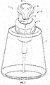
- FIG. 1 to 23 showing a first embodiment of a dispenser 9 in accordance with the present invention.
- the dispenser 9 includes a pump assembly 10 and a container 12.
- the container 12 is illustrated as being transparent.
- the container 12 is enclosed but for an opening 37, as seen in Figure 4 , provided at an axially outer end of a threaded neck 101 of the container which is coupled to a top wall 102 of the container 12.
- the top wall 102 merges into a side wall 103 and, hence, into a bottom wall 104.
- a liquid 105 is contained within the container 12 and the pump assembly 10 is adapted to discharge the liquid 105 from container 12.
- the pump assembly 10 has a piston chamber-forming body 14 and a piston-forming element 16.
- Each of the piston chamber-forming body 14 and the piston-forming element 16 are substantially disposed coaxially about a central axis 20.
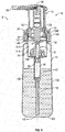
- coaxial reciprocal movement of the piston-forming element 16 relative the piston chamber-forming body 14 about the axis 20 between an axially extended position as shown in Figures 2 , 4 and 5 and an axially retracted position shown in Figures 3 and 6 , dispenses the liquid 105 from the container 12 out a discharge outlet 36 of the piston-forming element 16.
- the piston chamber-forming body 14 as seen in Figures 5 and 9 , comprises two major components, a collar member 38 and a tube member 39 which are fixedly secured together in a snap fit relation.
- the piston-forming element 16 includes as two lesser elements a one-way inlet valve 17 and a dip tube 19.
- the tube member 39 has a side wall 106 disposed coaxially about the axis 20 with a generally stepped configuration so as to define an axially inner fluid chamber 18 and an axially outer air chamber 118.
- the fluid chamber 18 is defined inside the wall 106 from an axially inner end 119 to an axially outer end 120 of the fluid chamber 18.
- the axially inner end 119 is defined by a radially inwardly extending shoulder 121 with an inlet opening 122 coaxially therethrough opening axially inwardly into a socket 123 open axially inwardly.
- the socket 123 is adapted to frictionally receive an inner end of the dip tube 19.
- the hollow tubular dip tube 19 extends downwardly to a lower end 107 disposed approximate the bottom wall 104 of the container 12.
- the one-way inlet valve 17 is secured in the inlet opening 122 in a snap fit and includes a resilient disc 124 that engages the radially inwardly directed inner surface of the wall 106 to permit fluid flow axially outwardly therepast yet to prevent fluid flow axially inwardly therepast as in a manner, for example, described in a similar one-way inlet valve in U.S. Patent No. 5,676,277 .
- the fluid chamber 18 is open at its axially outer end 120 into an inner end 125 of the air chamber 118.
- the air chamber 118 is defined within the wall 106 between its axially inner end 125 and an axially outer end 130. Thus, the fluid chamber 118 is open at its axially inner end 120 into the air chamber 118.
- the air chamber 118 is open axially outwardly at its axially outer end 130.
- the fluid chamber 118 is defined between its axially inner end 119 and its axially outer end 120 radially inwardly of an inner portion 131 of the wall 106 which is circular in cross-section, substantially cylindrical and has a diameter.
- the air chamber 118 is defined between its axially inner end 125 and its axially outer end 130 by an outer portion 132 of the wall 106 which is circular in cross-section, substantially cylindrical and has a diameter larger than the diameter of the inner wall portion 131 forming the fluid chamber 18.
- the wall 106 carries at the outer end 130 a radially outwardly extending snap flange 135 and spaced axially inwardly from the snap flange 135, a radially outwardly extending sealing flange 134.
- the collar member 38 is secured in a fixed snap fit relation on to the axially outer end 130 of the tube member 39.
- the collar member 38 has an inner guide tube 40 coaxially about the axis 20.
- the inner guide tube 40 is open both at an axially inner end 41 and an axially outer end 42.
- the guide tube 40 has a cylindrical radially inwardly directed inner guide surface 44 extending between its inner end 41 and its outer end 42.
- the collar member 38 includes a radially outwardly extending shoulder flange 140 merging into an outer collar tube 142 having a threaded radially inwardly directed surface 143 carrying threads for engagement with complementary threads on the threaded neck 101 of the container 12.
- an axially extending snap tube 144 extends axially inwardly from the shoulder flange 140.
- the snap tube 144 on the collar member 38 carries an axially inwardly directed shoulder for engagement with an axially outwardly directed shoulder on the snap flange 135 of the wall 106 of the tube member 39 to fixedly secure the collar member 38 and the tube member 39 coaxially about the axis 20 with the inner guide tube 40 disposed radially inwardly of the wall 106 of the tube member 39 about the outer end 130.
- the collar member 38 is secured to the container 12 with the threaded surface 143 of the collar member 38 engaging the threaded neck 101 on the container 12 and urging the sealing flange 134 of the tube member 38 into sealed engagement with the opening 37 of the container 12, preferably with a resilient annular gasket member 200 disposed axially therebetween.
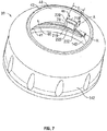
- the inner guide tube 40 carries a lug member 46 that extends radially inwardly from the inner guide surface 44.
- the lug member 46 as seen in Figure 7 has an axially outwardly directed outer axial lug stop surface 218, an axially inwardly directed inner axial lug stop surface 219, a circumferentially directed right lug side surface 220, a circumferentially directed left lug side surface 222, and a radially inwardly directed circumferential lug surface 223.
- the lug member 46 provides as a curved merger of the right lug side surface 220 and the circumferential lug surface 223, a camming surface 78.
- the lug member 46 is marked on Figure 7 to extend radially inwardly from the inner guide surface 44 over a circumferential extent C between the right lug side surface 220 and the left lug side surface 222, a radial extent R from the inner guide surface 44 to the circumferential lug surface 223 and an axial extent A between the outer axial lug stop surface 218 and the inner axial lug stop surface 219.
- piston-forming element 16 as comprising two major elements, namely, a piston member 24 and an actuator member 26.
- the piston-forming element 16 includes a foam generator 25 schematically illustrated in Figure 11 .
- the foam generator 25 is schematically illustrated as a cylindrical member comprising a pair of spaced screens 601, 602 bonded to the axial ends of a cylindrical porous sponge-like plug.
- the particular nature of the foam generator 25 is, however, not limited.
- the foam generator 25 is adapted to be received within a passageway 34 axially inwardly from an end cap 170 on the actuator member 26 and supported on a radially outwardly directed shoulder within the passageway 34.
- the particular nature of a foam generator 25 is not limited and the purpose of the foam generator is to generate a consistent mixture of a foamed air and liquid product on simultaneous passing of the air and liquid therethrough.
- the piston member 24 is best seen by itself in Figure 11 as being disposed coaxially about the axis 20.
- the piston-forming element 16 includes a central axially extending stem 32 with the passageway 34 therethrough closed at an axially inner end 150 and open at an axially outer end 151.
- the piston member 24 carries a reduced diameter axially innermost fluid piston portion 152 which is adapted to be coaxially received within the fluid chamber 18 to form a liquid pump 30.
- the fluid piston portion 152 includes a resilient inner disc 153 that engages the side wall 106 in the fluid chamber 118 to permit fluid flow axially outwardly therepast but to prevent fluid flow axially inwardly therepast.
- the fluid piston portion 152 includes an outer disc 154 that engages the side wall 106 in the fluid chamber 18 to prevent fluid flow axially therepast.
- Liquid ports 155 located on the stem 32 between the outer disc 154 and the inner disc 153 extend coaxially through the stem 32 into the passageway 34.
- the fluid 105 With reciprocal coaxial movement of the piston member 24 relative to the tube member 39, the fluid 105 is drawn upwardly from the container 12 though the dip tube 19 past the one-way inlet valve 17 into the fluid chamber 18 in a retraction stroke and in an opposite extension stroke, the fluid 105 is discharged axially outwardly past the inner disc 153 into an annular space 149 radially outward of the stem 32 and radially inward of the wall 106 and between the inner disc 153 and the outer disc 154 and hence via the liquid ports 155 radially through the stem 32 into the passageway 34 leading to the discharge outlet 36.
- the operation of the liquid pump 30 is substantially the same as described in U.S. Patent 5,676,277 referenced above. However, many other configurations of a piston pump may be adopted for the liquid pump 30 without departing from the present invention as defined in the appended claims.
- liquid pump 30 there is defined between the outer disc 154 and the one-way inlet valve 17, a liquid compartment 401 with a volume that varies with the axial position of the piston member 24 within the fluid chamber 18.
- transfer ports 156 are provided radially through the stem 32 into the passageway 34.
- annular air disc 157 extends radially outwardly from the stem 32.
- the air disc 157 extends radially from stem 32 at an axially outer end 174 of the air disc 157 as a radial shoulder 175 that bridges between the stem 32 and a generally cylindrical tubular portion 176 of the air disc 157.
- the tubular portion 176 extends coaxially about the axis 20 from the radial shoulder 175 axially inwardly to merge with at an axially inner end with the radially outwardly flange 177 carrying disc arms 161 and 162.
- the air disc 157 at its radial outer end carries the pair of resilient disc arms 161 and 162 which engage the inner surface of the wall 106 inside the air chamber 118 to provide a seal preventing flow axially inwardly or outwardly therepast.
- An air compartment 402 is defined annularly about the stem 32 radially between the stem 32 and the wall 106 about the air chamber 118 and axially between the air disc 157 and the outer disc 154.
- the air compartment 402 has a volume that varies with the axial position of the piston member 24 within the tube member 39 whereby an air pump 31 is formed.
- the volume of the air compartment 402 decreases forcing air through the transfer ports 156 into the passageway 34 simultaneously with the discharge of the liquid 105 from the pump liquid 30 into the passageway 34 for simultaneous discharge of air and liquid via the passageway 34 through the foam generator 25 to produce a foam of air and the liquid that is discharged to the discharge outlet 36.
- the volume of the air compartment 402 increases drawing via the discharge outlet 36 air from the atmosphere, as well as drawing any foam, air or liquid within the passageway 34 into the air compartment 402.
- a spring member 15 is disposed with the air chamber 118 engaged at an axially inner end of the spring member 15 on a radially extending shoulder 158 between the outer end 120 of the fluid chamber 18 and the inner end 125 of the air chamber 118 and at an axially inner end and at an axially outer end of the spring member 15 on the radial shoulder 175 of the air disc 157.
- the spring member 15 biases the piston member 24 and thereby the piston-forming element 16 axially outwardly relative to the piston chamber-forming body 14 to the extended position as shown in Figure 5 and is compressible to permit the piston-forming element 16 to be moved relative the piston chamber-forming body 14 from the extended position of Figure 5 to the retracted position of Figure 6 .
- the actuator member 26 includes at an axially outer end the radially extending end cap 170 from which an outer slide tube 48 extends axially inwardly from an axially outer end 49 of the outer slide tube 48 to an open axially inner slide tube end 50.
- the slide tube 48 extends coaxially about the axis 20 axially inwardly from the end cap 170.
- An inner stem tube 171 also extends coaxially about the axis 20 from the endcap 170 coaxially within the outer slide tube 48 to an axially inner end 172 of the inner stem tube 171.
- the actuator member 26 carries a radially outwardly extending discharge tube 96 that extends radially outwardly from the end cap 170 and carries the discharge outlet 36 at a radially outer end 97.
- An internal passage 98 extends radially through the discharge tube 96 to provide for communication between the discharge outlet 36 and the passageway 34 in the stem 32.
- the piston member 24 and the actuator member 26 are fixedly secured together with the inner stem tube 171 coaxially within the open outer end of the passageway 34 of the stem 32 of the piston member 24 in frictional engagement.
- the end cap 170 of the actuator member 26 provides an axially outer end of the actuator member 26 as an axially outwardly directed engagement surface 93 for the application of manual forces to move the piston-forming element 16 relative the piston chamber-forming body 14 axially from the extended position as seen in Figure 5 to the retracted position such as seen in Figure 6 .
- an air port 146 is provided radially through the wall 106 into the air chamber 118.
- Figure 4 illustrates the air port 146 as open on a radial outward side of the tube member 36 via an annular passageway 173 between the tube member 39 and the neck 101 of the container 12 into the interior of the container 12.
- the actuator member 26 carries the slide tube 48 which has a radially outwardly directed outer tubular slide tube wall 52 and a radially inwardly directed inner tubular slide tube wall 53.
- the outer slide tube wall 52 is circular in any cross-section normal the axis 20.
- the inner slide tube wall 53 is circular in any cross-section normal the axis 20.
- the slide tube 48 carries approximate its inner slide tube end 50 a radially outwardly extending annular end flange 202 presenting an axially outwardly directed stop shoulder 204.
- the engagement of the stop shoulder 204 on the slide tube 48 with the axially inner end 41 of the inner guide tube 40 of the collar member 38 limits axial outward sliding of the actuator member 26 relative to the collar member 38 and, hence, as seen in Figures 4 and 5 , limits the axial outward sliding of the piston-forming element 16 relative the piston chamber-forming body 14 in the extended position.
- the outer tubular side wall 52 of the slide tube 48 is in close relation to the radially inwardly directed inner guide surface 44 of the inner guide tube 40 on the collar member 38 so as to journal the actuator member 26 coaxially in the collar member 38 for both rotation about the axis 20 and coaxial sliding.
- the actuator member 26 would freely coaxially slide relative to the collar member 38 and the actuator member 26 would freely rotate relative to the collar member about the axis 20.
- the lug member 46 carries on the collar member 38 and extending radially inwardly from the inner guide surface 44 of the collar member 38 interacts with various motion control features provided on the slide tube 48 of the actuator member 26.
- These motion control features on the slide tube 48 include, as seen in Figure 15 , an axially extending slide channel 70, a stop slot 72 and a finger member 62.
- the axially extending slide channel 70 is provided on the slide tube 48 to extend radially inwardly from the outer tubular side tube wall 52 of the slide tube 48.
- the slide channel 70 is defined between two channel side walls 206 and 208 bridged by a channel base 210.
- the slide channel 70 is open radially outwardly over a circumferential extent between the side walls 206 and 208.
- the channel base 210 has a radially outwardly directed base surface 211 and a radially inwardly directed base surface 212.
- the slide channel 70 has a radial extent measured from the base surface 211 to a radius about the axis 20 in which the outer tubular slide tube wall 52 lies.
- the slide channel 70 is open at an axially inner end 220 at the inner slide tube end 50.
- the slide channel is closed at an axially outer end wall 221. While the actuator member 26 is in an operative rotational position relative to the collar member 38, the lug member 46 is received within the slide channel 70, which condition arises in the unlocked conditions of Figures 2 and 3 in which the lug member 46 is axially slidable within the slide channel 70 permitting reciprocal axial movement of the actuator member 26 between the retracted position of Figure 2 and the extended position of Figure 3 .
- the lug member 38 has its circumferential extent C and radial extent R complementary to the circumferential extent and radial extent of the slide channel 70 so as to provide for relative axial sliding of the lug member 38 within the slide channel 70.
- the stop slot 72 is provided on the slide tube 48 to extend radially inwardly from the outer slide tube wall 52 of the slide tube 48.
- the stop slot 72 as best seen in Figure 15 is cut entirely through the slide tube 48.
- the stop slot 72 is bordered by a circumferentially and radially extending axially outer axial slot stop surface 213 and with the stop slot 72 extending circumferentially between a radially and axially extending left slot side surface 214 and an axially extending right slot side surface 216.
- the stop slot 72 extends circumferentially between the left slot side surface 214 and the right slot side surface 216 axially from the axial slot stop surface 213 axially inwardly to an axially inner slot opening 217 into the stop slot 72 at the inner side tube end 50.
- the stop slot 72 has a circumferential extent between the left slot side surface 214 and the right slot side surface 216 and an axial extent between the axial slot stop surface 213 and the inner slot opening 217.
- the slide stop 72 also has a radial extent.
- the collar member 38 When the actuator member 26 and the collar member 38 are in an inoperative rotational position such as in Figures 1 , 16 , 17 and 18 , the collar member 38 is coaxially about the actuator member 26 and the lug member 46 extends radially inwardly from the collar member 38 engaged within the stop slot 72 on the slide tube 48 of the actuator member 26.
- the lug member 46 and the stop slot 72 are complementary sized as to their respective circumference extents and radially extents and axial extents respectively such that the lug member 46 is be received within the stop slot 72.
- the finger member 62 is provided on the slide tube 48 as a portion of the slide tube wall 52 between a pair of cut slots 54 and 55.
- Each of the cut slots 54 and 55 extends radially through the side wall tube 52 radially between the outer tubular slide tube wall 52 and the inner tubular slide tube wall 53.
- Each cut slot 54 and 55 extends axially from a respective axial inner slot end 56 and 57 open to the inner slide tube end 50 to a respective blind axial outer slot end 60 and 61 located spaced axially inwardly from the inner slide tube end 50.
- the cut slot 55 is provided as cut from the channel side wall 206 of the slide channel 70.
- the cut slot 54 is defined by the combination of the stop slot 72 and an axially outer slot portion 217 that extends axially outwardly from the stop slot 72.
- the finger member 62 is defined in the slide tube 48 circumferentially between the cut slots 54 and 55.
- the finger 62 extends from an axially inner distal end 64 of the finger member 62 to an axially outer end 66 of the finger member 62, where the finger member 62 merges into the slide tube wall 52 between the blind axial outer slot ends 60 and 61.
- the blind axial outer slot ends 60 and 61 are spaced axially outwardly from the inner slide tube end 50 an equal distance.
- the finger member 62 has a radially outwardly directed outer surface 224 that is concave mirroring the curvature of the outer tubular side wall 52 and a radially inwardly directed inner surface 225 that is convex and mirroring the curvature of the inner tubular side wall 53.
- the finger member 62 has a left side surface 226 that includes the right slot side surface 216 and on the opposite side a right side surface 227.
- the slide tube 48 is provided such that the finger member 62 is a resilient member that is deflectable by radially inward directed forces to move the distal end 64 the finger member 62 radially inwardly relative the slide tube wall 52.
- the finger member 62 is resilient and has an inherent bias to assume an unbiased condition as shown in Figures 13 to 15 conforming to the circular in cross-section shape of the slide tube 48.
- a radially inwardly directed force is applied to the finger member 62as schematically illustrated by the arrow F on Figure 13
- the finger member 62 deflects with movement of the distal end 64 of the finger member 62 radially inwardly relative the outer end 66 and, on release of such force F, the finger member 62 under its inherent bias moves towards its unbiased condition.
- the slide tube 48 is preferably made from materials having some inherent resiliency, preferably by injection molding as a unitary element from plastic materials. Suitable resiliency of the finger member 62 may be provided by the selection of the materials from which the slide
- the right slot side surface 216 of the stop slot 72 comprises a portion of the left side surface 226 of the finger member 62 within the stop slot 72.
- the right slot side surface 216 includes a cammed surface 80 which, while extending axially, is "beveled” so as to extend at an acute angle to an axially and radially extending plane including the axis 20 with a distance of any point on the cammed surface 80 increasing in circumferential distance from the left slot side surface 214 with increased radius from the axis 20.
- FIG. 16 to 19 are illustrations showing merely the actuator member 26 and the collar member 38 as coupled together and in which other components forming the pump assembly 10, not shown.
- FIGs 20 to 23 are illustrations showing merely the piston member 24, actuator member 26 and the collar member 38.
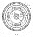
- FIGS 20 to 23 are cross-sectional views along section line D-D' in Figure 17 in the extended position but with the piston member 24 and actuator member 28 as the piston-forming element 16 in different rotational positions about the axis 20 relative the collar member 38.
- Figures 16 , 17 , 18 and 21 which illustrate the actuator member 26 and the collar member 38 coupled together in the locked condition and the inoperative rotational position.
- the outer axial lug stop surface 218 of the lug member 46 engages with the axial slot stop surface 213 of the stop slot 72 to limit coaxially outward sliding of the actuator member 26 relative to the collar member 38 thereby preventing operation of the liquid pump 30 and the air pump 31 to dispense the liquid and air.
- an angular vector A is indicated as the angle of rotation about the axis 20 between the left lug side surface 222 and the left slot side surface 214 as effectively nil.
- the actuator member 26 is manually rotated counterclockwise relative to the collar member 38 until the right lug side surface 220 of the lug member 46 first engages the right slot side surface 216 with the camming surface 78 on the lug member 46 first engaging the cammed surface 80 of the finger member 62 and assume the positions of Figures 18 and 22 in which, as seen in Figure 22 , the angular vector B about the axis between the left lug side surface 222 and the left slot side surface 214 is marginally increased over angular vector A in Figure 21 .
- the lug member 46 has moved counterclockwise past the finger member 62 and the finger member 62 under its inherent bias has moved radially outwardly from the defected condition shown in Figure 23 towards the unbiased condition as shown in Figure 20 .
- the lug member 46 is constrained within the side channel 70 by being disposed circumferential ly between the channel side walls 206 and 208 with the side surfaces of the finger member 62 in opposed relation to the channel slide walls 206 and 208.
- the lug member 46 once received within the slide channel 70 is maintained within the slide channel 70 preventing relative rotation of the actuator member 26 relative to the collar member 38 by reason of the lug member 46 being constrained between the channel side walls 206 and 208.
- the unlocked condition and operative rotational position illustrated in Figure 20 corresponds to the unlocked extended position shown in Figure 2 from which the actuator member 26 is free to slide coaxially relative to the collar member 38 between the extended position of Figure 5 and the retracted position of Figure 6 for operation of the liquid pump 30 and the air pump 31.
- Figure 19 illustrates the unlocked condition as shown in Figure 20 with the lug member 26 received within the side channel 70 in the extended position of Figures 2 and 5 .
- the actuator member 26 and the collar member 38 may be coupled together with the lug member 46 received with the stop slot 72. Subsequently, the piston member 24 may be coupled to the actuator member 26 and then the tube member 39 maybe coaxially disposed about the piston member 24 and coupled to the collar member 38.
- the various other components such as the one-way valve 17, the foam generator 25 and the spring member 95 are to be inserted at appropriate times in these assembly steps.
- Such an assembled pump 10 would thus have as an initial condition as in Figure 1 , that is, in a locked condition in the inoperative rotational position and the extended position with engagement of the lug member 46 in the stop slot 72 preventing axial sliding of the actuator member 26 to the retracted position, preventing rotation of the actuator member 26 clockwise and resisting rotation of the actuator member 26 counterclockwise relative to the collar member 38 unless sufficient relative rotational forces are applied to the actuator member 26 that engagement between the lug member 46 and the finger member 62 deflects the finger member 62 radially inwardly to permit the lug member 46 to rotate counterclockwise to be received within the slide channel 70 assuming the unlocked condition in the operative rotational position and extended position of Figure 2 .
- the actuator member 26 In the unlocked condition and extended position of Figure 2 , the actuator member 26 is free to move between the unlocked extended position of Figure 2 and the unlocked retracted position of Figure 3 to dispense the fluid and air. In the preferred embodiment of Figures 1 to 23 , once the lug member 46 becomes engaged within the slide channel 70 the lug member 46 cannot be moved out of the slide channel 70.
- the rotational forces required to be applied by a user in rotating the actuator member 26 such that engagement between the lug member 46 and the finger member 62 will deflect the finger member 62 sufficiently that the lug member 46 will move radially past the finger member 62 are preferably selected such that there is a clear tactical indication given to the user firstly that the actuator member 26 is in the inoperative rotational position relative to the collar member 38 and, secondly, that the finger member 62 has become received within the slide channel 70 and is in the operational rotational position.
- the tubular portion 176 of the air disc 157 carries a radially outwardly directed finger stopping surface 82.
- the tubular portion 176 is located radially inwardly from the finger member 62 with the radially outwardly directed finger stopping surface 82 opposed to the radially inwardly directed inner surface 225 of the finger member 62 and, as seen in Figure 23 , limits radial inward deflection of the finger member 62.
- the finger stopping surface 82 located radially inwardly from the finger member 62 is engaged by the finger member 62 and increases the resistance to deflecting the finger member 62 radially inwardly out of the path of the lug member 46, as can be advantageous to serve a number of purposes.
- the actuator member 26 and its slide tube 48 including the finger member 62 are integrally formed by injection molding from a material having desired properties with an inherent resiliency so as to provide the finger member 62 to assume an inherent unbiased position, permit deflection of the finger member 62 and return of the finger member 62 to the inherent unbiased position.
- Providing the finger stopping surface 82 located radially inwardly from the finger member 62 can assist in controlling deflection of the finger member 62. For example, in deflection of the finger member 62 the axially inner distal end 64 of the finger member 62 will come to engage the finger stopping surface 82 and limit further inward deflection of the distal end 64.
- the tubular portion 176 may be relatively rigid to prevent radial inward movement of the finger member 62 when engaged by the finger 62.
- increased radially inward deflection of the finger member 62 between its distal end 64 and its outer end 66 may be required to permit the lug member 46 to move circumferentially therepast thereby increasing the resistance required to deflect the finger member 62 outwardly out of the path of the lug member 46.
- the finger stopping surface 82 is resilient having an inherent bias to assume an inherent position and when deflected from the inherent position to return to the inherent position.
- the tubular portion 176 may provide for such resiliency and insofar as the finger member 62 is moved radially inwardly, such radial inwardly movement of the finger member 62 will deflect the finger stopping surface 82 radially inwardly with the finger stopping surface 82 resiliently biasing the finger member 62 radially outwardly towards the inherent biased position of the tubular portion 176.
- the tubular portion 176 may preferably be formed of a material that provides resiliency and is biased to return to an inherent position and will urge finger member 62 radially outwardly.
- the inherent resiliency of the tubular portion 176 provides at least stopping and preferably a resiliency.
- a separate annular spring member (not shown) could be provided and carried with the tubular portion 176 to provide in effect a spring to bias the finger member 62 radially outwardly.
- the finger member 62 in its unbiased condition as shown in Figure 21 is spaced radially from the finger stopping surface 82, that is, with the radially inwardly directed inner surface 225 of the finger member 62 spaced from the finger stopping surface 82.
- the finger member 62 as seen in the unbiased condition as shown in Figure 21 could have its radial thickness increased so as to provide the radially inwardly directed inner surface 225 of the finger member 62 closely adjacent the finger stopping surface 82 even when the finger member 62 is in its inherent unbiased position as seen in Figure 21 .
- Maintaining a resilient resistance to deflection of the finger member 62 inwardly and biasing the finger member 62 to move to its inherent position radially outwardly can be advantageous to ensure that a user on rotating the actuator member 26 relative to the collar member 38 receives tactical sensory feedback, that is, feedback perceptible by touch, indicative of the change in rotational positions as can be useful for a user to understand the relative position of the actuator member 26 and the collar 38.
- the camming surface 78 on the lug member 46 engages with the cammed surface 80 on the finger member 62 to deflect the finger member 62 radially inwardly so as to permit rotation of the actuator member 26 counterclockwise relative to the lug member 46, however, clockwise rotation of the actuator member 26 relative to the collar member 38 is prevented.
- Figure 24 shows a second embodiment of a pump in accordance with the present invention. Figure 24 is identical to Figure 20 but for two exceptions.
- the lug member 46 is modified to include as a curved merger of the left lug side surface 222 and the circumferential lug surface 223 a camming surface 178 and, as a second exception, the finger member 62 includes on its right side surface 227 a cammed surface 180.
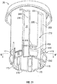
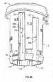
- Figure 25 illustrates a cross-sectional side view substantially the same as Figure 5 , but showing a pump assembly 10 in accordance with a third embodiment of the present invention.
- Figure 25 is identical to Figure 5 but for three exceptions.
- the transfer ports 156 through the stem 32 have been eliminated.
- an air transfer opening 208 has been provided radially through the tubular portion 176 of the air disc 157.
- the passageway 34 through the stem 32 has been reduced to have a simplified, reduced and more constant diameter, and the foam generator 25 is eliminated.
- the pump assembly 10 in accordance with the third embodiment of Figure 25 merely includes the liquid pump 30 and does not include an air pump. Air within the air compartment 402 is free to move through the air transfer opening 208 and, hence, to the atmosphere. No communication is provided from the air compartment 402 into the passageway 34. The operation of the pump assembly 10 in Figure 25 and the opening and closing of the air port 146 by the air disc 157 is unchanged and continues to provide selective passage of atmospheric air into the container 12.
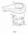
- Figure 26 showing a perspective view of an actuator member for a fourth embodiment of a pump assembly in accordance with the present invention.
- the actuator member of Figure 26 has close similarities to the actuator member 26 described with reference to that of the first embodiment as notably shown in Figure 14 .
- the stop slot 72 has been modified compared to the stop slot 72 in Figure 14 .
- dashed lines 406 delineate an axial portion 408 of the stop slot 72 from a circumferential portion 410 of the stop slot 72.
- the axial portion 408 guides and permits sliding of the lug member 46 axially outwardly relative to the actuator member 26 from the inner end opening 217 until the lug member 46 engages the outer stop surface 213.
- the circumferential portion 410 opens circumferentially into the axial portion 408 in a direction extends circumferentially away from the axial portion 408 and away from the finger member 62.
- the circumferential portion 410 is defined axially between the axial outer stop surface 213 and an outwardly directed axially inner stop shoulder 412.
- the circumferential portion 410 ends circumferentially at an axially and radially extending rotation stop surface 414 bridging between the outer stop surface 213 and the inner stop shoulder 412. While the lug member 46 is in the axial portion 410 engaged with the outer stop surface 213 against the bias of the spring 15, rotation of the actuator member 26 clockwise relative to the collar member 38 moves the lug member 46 circumferentially into the circumferential portion 410.
- the spring 15 biases the actuator member 26 axially outwardly relative the collar member 38 to the extended position in which extended position the lug member 46 is in a location axially inwardly from the circumferential portion 410 and with clockwise rotation of the lug member 46 prevented by engagement with the left slot side surface 214.
- the cammed surface 80 on the finger member 62 is shown to extend from the end flange 202 to the outer stop surface 213. This is preferred such that with the lug member 46 in the circumferential portion 410 rotation counterclockwise with sufficient force will result in the lug member 46 engaging and deflecting the finger member 62 radially inwardly.
- the cammed surface 80 may merely extend from the end flange 202 to just axially outwardly beyond the position the lug member 46 assumes in the extended position, in which case, the lug member 46 would need to move axially inwardly in the axial portion 408 before further rotation counterclockwise will engage the cammed surface 80 to deflect the finger member 62.
- the finger member 62 has a reduced radial thickness circumferentially adjacent the cammed surface 80 over a circumferentially extending slotway 407 provided between the end flange 202 and a circumferential extension of the outer stop surface 213.
- the cammed surface 80 is not provided on the end flange 202.
- FIG. 27 , 28 and 29 illustrate a fifth embodiment of a dispenser 9 and a pump 10 in accordance with the present invention.
- the actuator member 26 of Figure 27 is substantially identical to the actuator member 26 described with reference to the first embodiment as illustrated, for example, in Figure 12 to 15 and notably in Figure 15 .
- the slide channel 70 has a circumferential extent between the channel side walls 206 and 208 selected to be of a circumferential extent only marginally greater than the circumferential extent C of the lug member 46 so as to constrain the lug member 46 to slide axially within the slide channel 70 in a purely axial direction relatively closely proximate to the channel side walls 206 and 208.
- slide channel 70 is defined circumferentially between side wall 206 and side wall 208.
- the side walls 206 and 208 are spaced circumferentially an extent substantially greater than the circumferential extent of the lug member 46. In the embodiment of Figure 27 , the side walls 206 and 208 extend over the circumferential extent greater than 270 degrees. As a result, when the actuator member 26 is coupled to the collar member 38 with the lug member 46 received within the slide channel 70, the actuator member 26 may be manually rotated relative the collar member 38 to a number of different rotational positions as schematically illustrated in Figure 27 .
- the stop slot 72 and the finger member 62 is identical to that shown in Figure 15 .
- the slide channel 70 has, in any cross-section normal to the axis 20, a constant cross-section axially to the inner slide tube end 50 of the slide tube 40, and thus axially through the end flange 202.
- the embodiment of Figure 28 shows that it is not necessary that the side channel 70 extend through the end flange 202 or be open to the inner slide tube end 50.
- the slide channel 70 is at its axially inner end closed by end flange 202 and its stop shoulder 204.
- Figure 28 continues to show the cut slot 55 as extending axially inwardly to the inner slide tube end 50.
- the collar member 38 is assembled to the actuator member 26 sliding the lug member 46 axially outwardly into the stop slot 72 from which position by relative rotation of the actuator member 26, the lug member 46 may come to move past the finger member 62 to be located within the slide channel 70.
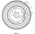
- Figure 31 is a pictorial view of an actuator member 26 for the pump 10 of the dispenser 9 in Figure 30 .
- the dispenser 9 and the pump 10 of Figure 30 are preferably identical in their components to the dispenser 9 and pump 10 of the first embodiment of Figures 1 to 23 .
- the actuator member 26 in Figure 31 is substantially identical to the actuator member 26 in the first embodiment as shown, for example, in Figures 12 to 15 and notably in Figure 15 .
- Each of the actuator member 26 of Figure 15 and the actuator member 26 of Figure 31 have an identical stop slot 72, an identical finger member 62 and an identical slide channel 70.
- each of these side channels 770 similar to the slide channel 70 have channel side walls 206 and 208, a channel base 210, a base surface 211, and a channel inner end 210. Between the slide channel 70 and the slide channel 770 adjacent thereto, there is provided a circumferentially extending part annular slotway 416. When the actuator member 26 is biased by the spring 15 to the extended position relative to the collar member 38, the lug member 46 is axially aligned with the slotway 416.
- each slotway 416 includes a pair of raised bosses 418 and 419 which prevent the lug member 46 from moving circumferentially through the slotway 416 unless a sufficient rotational force is applied to overcome the frictional interference between the lug member 46 and each boss 418.
- each pair of adjacent of the slide channels 770 are also connected to each other by a slotway 416.
- the lug member 46 can be rotated to different operational rotational positions in which the lug member 46 is received in one of the side channels 70 and 770 in which in each the actuator member 26 is axially slidable relative to the collar member 38 for operation of the pump 10.
- the plurality of different operational rotational positions that the actuator member 26 can assume relative to the collar member 38 with the lug member 46 within one of the side channels 70 and 770 to permit operation of the pump 10 is schematically illustrated in Figure 30 .
- Figure 33 showing a pictorial view of dispenser 9 with a pump assembly in accordance with a seventh embodiment that has close similarities to the dispenser of the sixth embodiment in Figures 30 to 32 .
- Figures 33 and 34 illustrate two different pictorial views of an actuator member 26 for the pump assembly 10 shown in Figure 33 .
- the actuator member 26 shown in Figures 33 and 34 is identical to the actuator member shown in Figures 31 and 32 , however, with the first exception that each of the slide channels 70 and 770 have a different axial extent.
- the actuator member 26 in Figures 33 to 35 is provided with volume indicia 300 for each of the slide channels 70 and 770 to indicate to the user the relative volume to be dispensed when the actuator member 26 is rotated to a position in line with one of the slide channels 70 and 770.
- indicia 301 is also provided on the actuator member 26 to indicate to the user a locked position.
- the indicia 300 and 301 are located on the actuator member 26 to be visible to a user when the actuator member 26 is in extended operation positions such as shown in Figure 35 .
- an indicator 303 is provided on the collar member 38 to indicate when the relative rotational position of the actuator member 26 on the collar member 38 corresponds to one of the indicia 300 and 301.
- the indicator 303 provides an indication that the actuator member 26 is in an inoperative locked position by reason of the indicator 303 being axially aligned with the indicia 301.
- the indicator 303 on the collar member 38 will come to be aligned with an appropriate one of the slide channels 70 and 170 with the indicia 301 for that slide channel being visible to the user.
- the pump assembly 10 illustrated in the first embodiment provides for the simultaneous dispensing of air and liquid through a foam generator 25 to produce a foam product.
- the configuration of the pump is, however, also suitable for simultaneous dispensing of air and liquid as a spray or mist in which case the foam generator 25 would not be provided and a suitable nozzle for producing a desired spray of the air and the liquid would be provided.
- the pump assembly includes a liquid pump or both a liquid pump and an air pump.
- a liquid pump or both a liquid pump and an air pump are shown to be piston pumps. In each of the liquid pump and air pump shown, discharge is provided in a retraction stroke.
- the particular nature of the piston pumps illustrated by the liquid pump and the air pump may, however, be substituted by other constructions for liquid pumps and air pumps which may, for example, discharge fluid in a withdrawal stroke.
- the preferred embodiments of the liquid pump provide a separate one-way inlet valve 17. It is known to a person skilled in the art by various configurations of stepped chambers that a liquid piston pump can be provided without the need for a separate one-way valve.
- the pump provides for simultaneous discharge of air and liquid in which the liquid pump and the air pump operate in sequence, that is, dispensing simultaneously in a retraction stroke. It is to be appreciated that in accordance with various liquid pumps and air pumps which may be desired to be utilized, the liquid pump may be out of phase with the air pump in the sense of the liquid pump discharging liquid into the air compartment during one stroke and the air pump discharging air and the liquid received from the liquid pump in another stroke.
- the preferred embodiment illustrates a pump assembly in which each of the components forming the pump are preferably formed as by injection molding from plastic materials and to provide for ease of manufacture from a minimal number of components.
- the piston chamber-forming body 14 is shown as being illustrated principally from two components, namely, the tube member 36 and the collar member 38. It is to be appreciated that these two components could possibly be injection molded as a single component, however, this would increase the complexity of the molds required for manufacture.
- the pump assemblies are adapted for use in a dispenser which preferably is a bottle top dispenser in which the fluid is dispensed upwardly.
- a dispenser which preferably is a bottle top dispenser in which the fluid is dispensed upwardly.
- pump assemblies could be developed which utilize similar lug members and motion controlling features yet permit dispensing of the fluid downwardly for in other orientations such as horizontally. Modifications of the liquid and/or air pumps can be made to facilitate the direction that fluid needs to be moved yet still use a similar interaction of the lug member and motion controlling features.
- the dispenser 9 is adapted to be placed on a support surface such as a table and as such a tabletop dispenser is preferably adapted for dispensing hand cleaning fluid from hand cleaning disinfectants and hand cleaning creams.
Landscapes
- Engineering & Computer Science (AREA)
- Mechanical Engineering (AREA)
- Reciprocating Pumps (AREA)
Claims (10)
- Ensemble de pompe (10) pour distribuer un liquide à partir d'un récipient (12) comprenant:un corps formant chambre de piston (14) ayant une chambre de fluide cylindrique (18) disposée autour d'un axe (20) et ouverte à une extrémité axialement extérieure (120),un élément formant piston (16) comprenant un organe de piston (24) et un organe d'actionnement (26),l'élément de piston (24) s'étendant depuis l'organe d'actionnement (26) coaxialement vers l'intérieur à travers l'extrémité extérieure (120) de la chambre de fluide (18) dans la chambre de fluide (18) et engageant la chambre de fluide (18) pour former une pompe à liquide (30),l'élément formant piston (16) comprenant une tige centrale s'étendant axialement (32) avec un passage (34) à travers celle-ci pour le passage du liquide refoulé par la pompe à liquide (30) axialement vers l'extérieur vers une sortie de refoulement (36) sur l'organe d'actionnement (26) axialement vers l'extérieur du corps formant chambre de piston (14),dans lequel, lors d'un mouvement alternatif coaxial de l'élément formant piston (16) par rapport au corps formant chambre de piston (14) autour de l'axe (20) entre une position axiale rétractée et une position axiale étendue, la pompe à liquide (30) distribue le liquide du récipient (12) par la sortie de décharge (36),le corps formant chambre de piston (14) comprenant un élément de collier (38) pour l'engagement avec une ouverture (37) du récipient (12), caractérisé par:l'élément de collier (38) ayant un tube de guidage intérieur (40) coaxialement autour de l'axe (20) ouvert à la fois à une extrémité axialement intérieure (41) et à une extrémité axialement extérieure (42), le tube de guidage (40) ayant une surface de guidage intérieure cylindrique (44) dirigée radialement vers l'intérieur,un élément d'ergot (46) s'étendant radialement vers l'intérieur à partir de la surface de guidage intérieure (44),l'élément d'ergot (46) s'étendant radialement vers l'intérieur à partir de la surface de guidage interne (44) sur une étendue circonférentielle C, une étendue radiale R et une étendue axiale A,l'élément formant piston (16) ayant un tube coulissant extérieur (48) fixé à l'organe d'actionnement (26) à une extrémité axialement extérieure (49) et s'étendant axialement vers l'intérieur jusqu'à une extrémité axialement intérieure ouverte du tube coulissant (50),le tube coulissant (48) coaxialement autour de l'élément de piston (24) radialement vers l'extérieur autour de l'élément de piston (24),le tube coulissant (48) ayant une paroi tubulaire extérieure (52) dirigée radialement vers l'extérieur,une paire de fentes découpées (54, 55) s'étendant axialement et espacées circonférentiellement, chacune découpant radialement la paroi du tube coulissant (52) depuis une extrémité de fente intérieure respective (56, 57) ouverte sur l'extrémité intérieure du tube coulissant (50) jusqu'à une extrémité de fente extérieure aveugle respective (60, 61) située à distance axiale vers l'extérieur de l'extrémité intérieure du tube coulissant (50),un premier élément de doigt (62) défini dans la paroi du tube coulissant (52) entre les fentes découpées (54, 55), le premier élément de doigt (62) s'étendant d'une extrémité distale axialement intérieure (64) du premier élément de doigt (62) à une extrémité axialement extérieure (66) du premier élément de doigt (62) où le premier élément de doigt (62) se fond dans la paroi du tube coulissant (52) entre les extrémités des fentes extérieures (60) et (61),le premier élément de doigt (62) pouvant être dévié par des forces dirigées radialement vers l'intérieur pour déplacer l'extrémité distale (64) radialement vers l'intérieur par rapport à la paroi du tube coulissant (52),le tube de glissement (48) ayant un premier canal de glissement (70) s'étendant axialement et radialement vers l'intérieur à partir de la paroi du tube de glissement (52),le premier canal latéral (70) et l'élément d'ergot (46) sont dimensionnés de manière complémentaire en termes d'étendue circonférentielle et d'étendue radiale de telle sorte que lorsque le tube coulissant (48) est tourné autour de l'axe (20) par rapport au tube de guidage (40) dans une première position de rotation de fonctionnement, l'élément d'ergot (46) coulisse axialement dans le premier canal latéral (70) permettant un coulissement coaxial relatif entre la position axiale rétractée et la position axiale étendue pour le fonctionnement de la pompe à liquide (30) pour distribuer le liquide,le tube coulissant (48) ayant une première fente d'arrêt (72) s'étendant axialement et s'étendant radialement vers l'intérieur dans la paroi du tube coulissant (52),la première fente d'arrêt (72) et l'élément d'ergot (46) sont dimensionnés de manière complémentaire en étendue circonférentielle et en étendue radiale de telle sorte que lorsque le tube coulissant (48) est tourné autour de l'axe (20) par rapport au tube de guidage (40) dans une première position de rotation inopérante, l'élément d'ergot (46) est reçu dans la première fente d'arrêt (72) et l'engagement entre le tube coulissant (48) et le tube de guidage (40) limite le coulissement coaxial relatif pour empêcher le fonctionnement de la pompe à liquide (30) pour distribuer le liquide,le premier élément de doigt (62) situé sur le tube de glissement (48) sur la circonférence entre le premier canal de glissement (70) et la première fente d'arrêt (72),en rotation relative du tube de guidage (40) et du tube coulissant (48) autour de l'axe (20) de la première position de rotation inopérante à la première position de rotation opérante, le premier élément de doigt (62) bloque le mouvement circonférentiel de l'élément d'ergot (46) jusqu'à ce que, par rotation relative autour de l'axe (20), une surface de came (78) de l'élément d'ergot (46) et une surface à came (80) sur le premier élément de doigt (62) s'engagent en déviant le premier élément de doigt (62) radialement vers l'intérieur hors de la trajectoire de l'élément d'ergot (46) permettant à l'élément d'ergot (46) de tourner circonférentiellement devant lui de la première position de rotation inopérante à la première position de rotation opérationnelle.
- Ensemble de pompe selon la revendication 1, dans lequel l'élément formant piston (16) portant une surface d'arrêt de doigt (82) située radialement vers l'intérieur du premier élément de doigt (62) limitant la déviation radiale vers l'intérieur du premier élément de doigt (62).
- Ensemble de pompe selon la revendication 2, dans lequel, lors de la déflexion radiale vers l'intérieur du premier élément de doigt (62), la surface d'arrêt de doigt (82) située radialement vers l'intérieur à partir du premier élément de doigt (62) est engagée par le premier élément de doigt (62) et augmente la résistance à la déflexion du premier élément de doigt (62) radialement vers l'intérieur hors du trajet de l'élément d'ergot (46).
- Ensemble de pompe selon la revendication 3, dans lequel la surface d'arrêt du doigt (82) est élastique, ayant une sollicitation inhérente pour prendre une position inhérente et, lorsqu'elle est déviée de la position inhérente revient à la position inhérente, la surface d'arrêt du doigt (82) située radialement vers l'intérieur à partir du premier élément de doigt (62) est engagée par le premier élément de doigt (62) et sollicite élastiquement le premier élément de doigt (62) radialement vers l'extérieur,
la surface d'arrêt du doigt (82) est portée sur la tige (32) de l'élément formant le piston (16),
la surface d'arrêt du doigt (82) comprend une surface cylindrique dirigée radialement vers l'extérieur de la tige (32) coaxiale à l'axe (20). - Ensemble de pompe selon l'une quelconque des revendications 1 à 4, dans lequel, lorsque le tube coulissant (48) est dans la première position de rotation inopérante avec l'élément d'ergot (46) reçu dans la première fente d'arrêt (72), l'engagement entre une surface d'arrêt d'ergot axiale extérieure dirigée axialement vers l'extérieur (218) sur l'élément d'ergot (46) et une surface d'arrêt de fente axiale dirigée axialement vers l'intérieur (213) de la première fente d'arrêt (72) limite le coulissement coaxial relatif de l'élément d'ergot (46) dans la première fente d'arrêt (72) axialement vers l'extérieur.
- Ensemble de pompe selon l'une quelconque des revendications 1 à 5, dans lequel:l'extrémité intérieure du tube coulissant (50) porte une bride d'extrémité annulaire s'étendant radialement vers l'extérieur (202) avec un épaulement de butée (204) dirigé axialement vers l'extérieur,la bride d'extrémité (202) située axialement à l'intérieur de l'extrémité axialement intérieure (41) du tube de guidage (40) pour engager une surface de butée (92) dirigée axialement vers l'intérieur sur l'extrémité axialement intérieure (41) du tube de guidage (40) pour limiter le mouvement axial vers l'extérieur de l'élément formant piston (16) par rapport au corps formant chambre de piston (14) dans la position axiale étendue.
- Ensemble de pompe selon l'une quelconque des revendications 1 à 6, dans lequel le premier canal de coulissement (70) comprend des parois latérales de canal (206, 208) qui engagent l'élément d'ergot (46) pour empêcher la rotation à partir de la première position de rotation opérationnelle une fois que l'élément d'ergot(46) est dans le premier canal de coulissement (70).
- Ensemble de pompe selon l'une quelconque des revendications 1 à 7, dans lequel l'organe d'actionnement (26) portant à une extrémité axialement extérieure (94) une surface d'engagement (93) dirigée axialement vers l'extérieur pour l'application de forces manuelles afin de déplacer l'élément formant piston (16) vers la position axiale rétractée
un élément de ressort (95) disposé entre le corps formant chambre de piston (14) et l'élément formant le piston (16), qui sollicite l'élément formant le piston (16) vers la position axiale étendue,
l'organe d'actionnement (26) comprend un tube de décharge (96) s'étendant radialement avec la sortie de décharge (36) à une extrémité radialement extérieure (97) et un passage interne (98) dirigeant le liquide du passage (34) dans la tige (32) radialement vers l'extérieur vers la sortie de décharge (36). - Ensemble de pompe selon l'une quelconque des revendications 1 à 8, dans lequel:le corps formant chambre de piston (14) ayant une chambre à air cylindrique (118) disposée autour de l'axe (20) ayant une extrémité axialement intérieure et une extrémité axialement extérieure,l'extrémité axialement extérieure (120) de la chambre à fluide (18) débouchant dans la chambre à air (118),l'élément de piston (24) s'étendant depuis l'organe d'actionnement (26) coaxialement vers l'intérieur à travers l'extrémité extérieure de la chambre à air (118) dans la chambre à fluide (18),l'élément de piston (24) engageant la chambre à air (118) pour former une pompe à air (31) pour l'évacuation de l'air dans le passage (34) de la tige (32) pour le passage simultané du liquide évacué par la pompe à liquide (30) et de l'air évacué par la pompe à air (31) axialement vers l'extérieur vers la sortie d'évacuation (36),dans lequel, lors du mouvement réciproque coaxial de l'élément formant piston (16) par rapport au corps formant chambre de piston (14) autour de l'axe (20) entre la position axiale rétractée et la position axiale étendue, la pompe à liquide (30) distribue le liquide du récipient (12) par la sortie de décharge (36) et la pompe à air (31) décharge l'air par la sortie de décharge (36).
- Ensemble de pompe selon l'une quelconque des revendications 1 à 9, dans lequel le premier élément de doigt (62) est élastique et a une sollicitation inhérente pour prendre une position inhérente et, lorsqu'il est dévié radialement vers l'intérieur à partir de la position inhérente, revient à la position inhérente.
Applications Claiming Priority (1)
| Application Number | Priority Date | Filing Date | Title |
|---|---|---|---|
| CA2935908A CA2935908C (fr) | 2016-07-12 | 2016-07-12 | Pompe a piston comportant des pistons bloquants |
Publications (2)
| Publication Number | Publication Date |
|---|---|
| EP3269455A1 EP3269455A1 (fr) | 2018-01-17 |
| EP3269455B1 true EP3269455B1 (fr) | 2020-10-21 |
Family
ID=59276577
Family Applications (1)
| Application Number | Title | Priority Date | Filing Date |
|---|---|---|---|
| EP17179256.7A Active EP3269455B1 (fr) | 2016-07-12 | 2017-07-03 | Pompe à pistons verrouillables |
Country Status (3)
| Country | Link |
|---|---|
| US (1) | US9999896B2 (fr) |
| EP (1) | EP3269455B1 (fr) |
| CA (1) | CA2935908C (fr) |
Families Citing this family (7)
| Publication number | Priority date | Publication date | Assignee | Title |
|---|---|---|---|---|
| US11161127B2 (en) | 2018-03-29 | 2021-11-02 | Op-Hygiene Ip Gmbh | Two stage foam pump and method of producing foam |
| EP3897282A4 (fr) * | 2018-12-19 | 2022-09-07 | GlaxoSmithKline Consumer Healthcare Holdings (US) LLC | Applicateur de dose variable |
| WO2020222631A1 (fr) * | 2019-04-29 | 2020-11-05 | Gonzalez Calleja Humberto | Pompe à siphon manuelle pour transvaser des liquides |
| CA3078207A1 (fr) | 2020-04-28 | 2021-10-28 | Op-Hygiene Ip Gmbh | Distributeur de nettoyant pour les mains sur pied |
| JP7485541B2 (ja) * | 2020-05-01 | 2024-05-16 | 株式会社三谷バルブ | ポンプおよびポンプ式製品 |
| IT202100025532A1 (it) * | 2021-10-07 | 2023-04-07 | Silgan Dispensing Systems Milano S R L | Pompa ad azionamento manuale |
| EP4658142A1 (fr) * | 2023-02-01 | 2025-12-10 | Silgan Dispensing Systems Corporation | Indicateur dans un distributeur moulé et ses procédés de fabrication |
Family Cites Families (19)
| Publication number | Priority date | Publication date | Assignee | Title |
|---|---|---|---|---|
| US4057176A (en) * | 1975-07-18 | 1977-11-08 | Plastic Research Products, Inc. | Manually operated spray pump |
| US4343417A (en) * | 1980-02-13 | 1982-08-10 | Corsette Douglas Frank | Dispensing pump locking means |
| US4433799A (en) * | 1982-03-31 | 1984-02-28 | Calmar, Inc. | Liquid dispensing pump arrangement with selective stroke restriction |
| US4871092A (en) * | 1982-07-10 | 1989-10-03 | Ing. Erich Pfeiffer Gmbh & Co. Kg | Atomizing or metering pump |
| JPS6227060A (ja) * | 1985-07-19 | 1987-02-05 | リ−レツクス・コ−ポレ−シヨン | 下方にロツキングを行なうさん布用ポンプ |
| US4773567A (en) * | 1986-04-21 | 1988-09-27 | Stoody William R | Child resistant latching actuator for aerosol/pump valve |
| US4991746A (en) * | 1989-07-07 | 1991-02-12 | Emson Research Inc. | Modular pump having a locking rotatable sleeve |
| US5676277A (en) | 1991-05-20 | 1997-10-14 | Ophardt; Heiner | Disposable plastic liquid pump |
| US5664703A (en) * | 1994-02-28 | 1997-09-09 | The Procter & Gamble Company | Pump device with collapsible pump chamber having supply container venting system and integral shipping seal |
| US5518147A (en) * | 1994-03-01 | 1996-05-21 | The Procter & Gamble Company | Collapsible pump chamber having predetermined collapsing pattern |
| US5899363A (en) * | 1997-12-22 | 1999-05-04 | Owens-Illinois Closure Inc. | Pump dispenser having a locking system with detents |
| DE10007638A1 (de) * | 2000-02-19 | 2001-08-23 | Pfeiffer Erich Gmbh & Co Kg | Spender für Medien |
| US6612468B2 (en) * | 2000-09-15 | 2003-09-02 | Rieke Corporation | Dispenser pumps |
| US6443331B1 (en) * | 2001-10-24 | 2002-09-03 | Saint-Gobain Calmer Inc. | Metered dispenser with pull fill mechanism |
| US6695171B2 (en) * | 2002-02-12 | 2004-02-24 | Seaquistperfect Dispensing Foreign, Inc. | Pump dispenser |
| US20070080174A1 (en) * | 2005-10-06 | 2007-04-12 | Coe Matthew T | Fluid dispenser with a safety dispensing actuator and fluid dispensing product containing the same |
| US20070080173A1 (en) * | 2005-10-06 | 2007-04-12 | Coe Matthew T | Fluid dispenser with a safety dispensing actuator |
| US7735688B2 (en) | 2006-10-10 | 2010-06-15 | Meadwestvaco Calmar, Inc. | Rotating collar and locking and venting closure connector for an air foaming pump dispenser |
| JP6227060B2 (ja) | 2016-06-20 | 2017-11-08 | 能美防災株式会社 | 支援システム |
-
2016
- 2016-07-12 CA CA2935908A patent/CA2935908C/fr active Active
-
2017
- 2017-07-03 EP EP17179256.7A patent/EP3269455B1/fr active Active
- 2017-07-10 US US15/645,149 patent/US9999896B2/en active Active
Non-Patent Citations (1)
| Title |
|---|
| None * |
Also Published As
| Publication number | Publication date |
|---|---|
| CA2935908C (fr) | 2023-10-17 |
| US9999896B2 (en) | 2018-06-19 |
| CA2935908A1 (fr) | 2018-01-12 |
| EP3269455A1 (fr) | 2018-01-17 |
| US20180015489A1 (en) | 2018-01-18 |
Similar Documents
| Publication | Publication Date | Title |
|---|---|---|
| EP3269455B1 (fr) | Pompe à pistons verrouillables | |
| US5687884A (en) | Metering device for dispensing constant unit doses | |
| US4640444A (en) | Pump dispenser with slidable trigger | |
| EP3219395B1 (fr) | Pompe en trois parties | |
| US3759426A (en) | Manually-operated liquid dispenser | |
| US4452379A (en) | Pump dispenser with one-piece stretchable biasing member and valve | |
| EP2641521B1 (fr) | Pompe de précharge adaptative | |
| KR101922512B1 (ko) | 유체 디스펜서 헤드 | |
| CA2841279A1 (fr) | Pompe a mousse a chambre d'air multiple | |
| US7959037B2 (en) | Severable piston pump | |
| US5356049A (en) | Hand pump assembly with a pump mechanism which is independent of the pump housing | |
| US4179049A (en) | Pump dispenser | |
| EP2228139B1 (fr) | Disque à deux joints pour pompe à piston | |
| US20130336823A1 (en) | Drawback check valve | |
| EP2676736B1 (fr) | Piston de cloche télescopique pour pompe | |
| US10174754B2 (en) | Displacement pump | |
| CA2517326C (fr) | Pompe a mousse avec ressort | |
| WO2019238237A1 (fr) | Pompe à piston manuel pour un contenant de fluide | |
| EP2676737B1 (fr) | Clapet anti-retour avec rappel | |
| EP3845104B1 (fr) | Pompe à tige stationnaire de sortie |
Legal Events
| Date | Code | Title | Description |
|---|---|---|---|
| PUAI | Public reference made under article 153(3) epc to a published international application that has entered the european phase |
Free format text: ORIGINAL CODE: 0009012 |
|
| STAA | Information on the status of an ep patent application or granted ep patent |
Free format text: STATUS: THE APPLICATION HAS BEEN PUBLISHED |
|
| AK | Designated contracting states |
Kind code of ref document: A1 Designated state(s): AL AT BE BG CH CY CZ DE DK EE ES FI FR GB GR HR HU IE IS IT LI LT LU LV MC MK MT NL NO PL PT RO RS SE SI SK SM TR |
|
| AX | Request for extension of the european patent |
Extension state: BA ME |
|
| STAA | Information on the status of an ep patent application or granted ep patent |
Free format text: STATUS: REQUEST FOR EXAMINATION WAS MADE |
|
| 17P | Request for examination filed |
Effective date: 20180627 |
|
| RBV | Designated contracting states (corrected) |
Designated state(s): AL AT BE BG CH CY CZ DE DK EE ES FI FR GB GR HR HU IE IS IT LI LT LU LV MC MK MT NL NO PL PT RO RS SE SI SK SM TR |
|
| STAA | Information on the status of an ep patent application or granted ep patent |
Free format text: STATUS: EXAMINATION IS IN PROGRESS |
|
| 17Q | First examination report despatched |
Effective date: 20181109 |
|
| GRAP | Despatch of communication of intention to grant a patent |
Free format text: ORIGINAL CODE: EPIDOSNIGR1 |
|
| STAA | Information on the status of an ep patent application or granted ep patent |
Free format text: STATUS: GRANT OF PATENT IS INTENDED |
|
| RIC1 | Information provided on ipc code assigned before grant |
Ipc: B05B 7/00 20060101ALI20191007BHEP Ipc: B05B 11/00 20060101AFI20191007BHEP |
|
| INTG | Intention to grant announced |
Effective date: 20191113 |
|
| GRAJ | Information related to disapproval of communication of intention to grant by the applicant or resumption of examination proceedings by the epo deleted |
Free format text: ORIGINAL CODE: EPIDOSDIGR1 |
|
| STAA | Information on the status of an ep patent application or granted ep patent |
Free format text: STATUS: EXAMINATION IS IN PROGRESS |
|
| INTC | Intention to grant announced (deleted) | ||
| GRAP | Despatch of communication of intention to grant a patent |
Free format text: ORIGINAL CODE: EPIDOSNIGR1 |
|
| STAA | Information on the status of an ep patent application or granted ep patent |
Free format text: STATUS: GRANT OF PATENT IS INTENDED |
|
| INTG | Intention to grant announced |
Effective date: 20200506 |
|
| GRAS | Grant fee paid |
Free format text: ORIGINAL CODE: EPIDOSNIGR3 |
|
| GRAA | (expected) grant |
Free format text: ORIGINAL CODE: 0009210 |
|
| STAA | Information on the status of an ep patent application or granted ep patent |
Free format text: STATUS: THE PATENT HAS BEEN GRANTED |
|
| AK | Designated contracting states |
Kind code of ref document: B1 Designated state(s): AL AT BE BG CH CY CZ DE DK EE ES FI FR GB GR HR HU IE IS IT LI LT LU LV MC MK MT NL NO PL PT RO RS SE SI SK SM TR |
|
| REG | Reference to a national code |
Ref country code: GB Ref legal event code: FG4D |
|
| REG | Reference to a national code |
Ref country code: CH Ref legal event code: EP |
|
| REG | Reference to a national code |
Ref country code: IE Ref legal event code: FG4D |
|
| REG | Reference to a national code |
Ref country code: DE Ref legal event code: R096 Ref document number: 602017025736 Country of ref document: DE |
|
| REG | Reference to a national code |
Ref country code: AT Ref legal event code: REF Ref document number: 1325303 Country of ref document: AT Kind code of ref document: T Effective date: 20201115 |
|
| REG | Reference to a national code |
Ref country code: AT Ref legal event code: MK05 Ref document number: 1325303 Country of ref document: AT Kind code of ref document: T Effective date: 20201021 |
|
| REG | Reference to a national code |
Ref country code: NL Ref legal event code: MP Effective date: 20201021 |
|
| PG25 | Lapsed in a contracting state [announced via postgrant information from national office to epo] |
Ref country code: GR Free format text: LAPSE BECAUSE OF FAILURE TO SUBMIT A TRANSLATION OF THE DESCRIPTION OR TO PAY THE FEE WITHIN THE PRESCRIBED TIME-LIMIT Effective date: 20210122 Ref country code: FI Free format text: LAPSE BECAUSE OF FAILURE TO SUBMIT A TRANSLATION OF THE DESCRIPTION OR TO PAY THE FEE WITHIN THE PRESCRIBED TIME-LIMIT Effective date: 20201021 Ref country code: NO Free format text: LAPSE BECAUSE OF FAILURE TO SUBMIT A TRANSLATION OF THE DESCRIPTION OR TO PAY THE FEE WITHIN THE PRESCRIBED TIME-LIMIT Effective date: 20210121 Ref country code: NL Free format text: LAPSE BECAUSE OF FAILURE TO SUBMIT A TRANSLATION OF THE DESCRIPTION OR TO PAY THE FEE WITHIN THE PRESCRIBED TIME-LIMIT Effective date: 20201021 Ref country code: PT Free format text: LAPSE BECAUSE OF FAILURE TO SUBMIT A TRANSLATION OF THE DESCRIPTION OR TO PAY THE FEE WITHIN THE PRESCRIBED TIME-LIMIT Effective date: 20210222 Ref country code: RS Free format text: LAPSE BECAUSE OF FAILURE TO SUBMIT A TRANSLATION OF THE DESCRIPTION OR TO PAY THE FEE WITHIN THE PRESCRIBED TIME-LIMIT Effective date: 20201021 |
|
| REG | Reference to a national code |
Ref country code: LT Ref legal event code: MG4D |
|
| PG25 | Lapsed in a contracting state [announced via postgrant information from national office to epo] |
Ref country code: SE Free format text: LAPSE BECAUSE OF FAILURE TO SUBMIT A TRANSLATION OF THE DESCRIPTION OR TO PAY THE FEE WITHIN THE PRESCRIBED TIME-LIMIT Effective date: 20201021 Ref country code: BG Free format text: LAPSE BECAUSE OF FAILURE TO SUBMIT A TRANSLATION OF THE DESCRIPTION OR TO PAY THE FEE WITHIN THE PRESCRIBED TIME-LIMIT Effective date: 20210121 Ref country code: LV Free format text: LAPSE BECAUSE OF FAILURE TO SUBMIT A TRANSLATION OF THE DESCRIPTION OR TO PAY THE FEE WITHIN THE PRESCRIBED TIME-LIMIT Effective date: 20201021 Ref country code: PL Free format text: LAPSE BECAUSE OF FAILURE TO SUBMIT A TRANSLATION OF THE DESCRIPTION OR TO PAY THE FEE WITHIN THE PRESCRIBED TIME-LIMIT Effective date: 20201021 Ref country code: IS Free format text: LAPSE BECAUSE OF FAILURE TO SUBMIT A TRANSLATION OF THE DESCRIPTION OR TO PAY THE FEE WITHIN THE PRESCRIBED TIME-LIMIT Effective date: 20210221 Ref country code: AT Free format text: LAPSE BECAUSE OF FAILURE TO SUBMIT A TRANSLATION OF THE DESCRIPTION OR TO PAY THE FEE WITHIN THE PRESCRIBED TIME-LIMIT Effective date: 20201021 Ref country code: ES Free format text: LAPSE BECAUSE OF FAILURE TO SUBMIT A TRANSLATION OF THE DESCRIPTION OR TO PAY THE FEE WITHIN THE PRESCRIBED TIME-LIMIT Effective date: 20201021 |
|
| PG25 | Lapsed in a contracting state [announced via postgrant information from national office to epo] |
Ref country code: HR Free format text: LAPSE BECAUSE OF FAILURE TO SUBMIT A TRANSLATION OF THE DESCRIPTION OR TO PAY THE FEE WITHIN THE PRESCRIBED TIME-LIMIT Effective date: 20201021 |
|
| REG | Reference to a national code |
Ref country code: DE Ref legal event code: R097 Ref document number: 602017025736 Country of ref document: DE |
|
| PG25 | Lapsed in a contracting state [announced via postgrant information from national office to epo] |
Ref country code: CZ Free format text: LAPSE BECAUSE OF FAILURE TO SUBMIT A TRANSLATION OF THE DESCRIPTION OR TO PAY THE FEE WITHIN THE PRESCRIBED TIME-LIMIT Effective date: 20201021 Ref country code: EE Free format text: LAPSE BECAUSE OF FAILURE TO SUBMIT A TRANSLATION OF THE DESCRIPTION OR TO PAY THE FEE WITHIN THE PRESCRIBED TIME-LIMIT Effective date: 20201021 Ref country code: SM Free format text: LAPSE BECAUSE OF FAILURE TO SUBMIT A TRANSLATION OF THE DESCRIPTION OR TO PAY THE FEE WITHIN THE PRESCRIBED TIME-LIMIT Effective date: 20201021 Ref country code: LT Free format text: LAPSE BECAUSE OF FAILURE TO SUBMIT A TRANSLATION OF THE DESCRIPTION OR TO PAY THE FEE WITHIN THE PRESCRIBED TIME-LIMIT Effective date: 20201021 Ref country code: SK Free format text: LAPSE BECAUSE OF FAILURE TO SUBMIT A TRANSLATION OF THE DESCRIPTION OR TO PAY THE FEE WITHIN THE PRESCRIBED TIME-LIMIT Effective date: 20201021 Ref country code: RO Free format text: LAPSE BECAUSE OF FAILURE TO SUBMIT A TRANSLATION OF THE DESCRIPTION OR TO PAY THE FEE WITHIN THE PRESCRIBED TIME-LIMIT Effective date: 20201021 |
|
| PLBE | No opposition filed within time limit |
Free format text: ORIGINAL CODE: 0009261 |
|
| STAA | Information on the status of an ep patent application or granted ep patent |
Free format text: STATUS: NO OPPOSITION FILED WITHIN TIME LIMIT |
|
| PG25 | Lapsed in a contracting state [announced via postgrant information from national office to epo] |
Ref country code: DK Free format text: LAPSE BECAUSE OF FAILURE TO SUBMIT A TRANSLATION OF THE DESCRIPTION OR TO PAY THE FEE WITHIN THE PRESCRIBED TIME-LIMIT Effective date: 20201021 |
|
| 26N | No opposition filed |
Effective date: 20210722 |
|
| PG25 | Lapsed in a contracting state [announced via postgrant information from national office to epo] |
Ref country code: IT Free format text: LAPSE BECAUSE OF FAILURE TO SUBMIT A TRANSLATION OF THE DESCRIPTION OR TO PAY THE FEE WITHIN THE PRESCRIBED TIME-LIMIT Effective date: 20201021 Ref country code: AL Free format text: LAPSE BECAUSE OF FAILURE TO SUBMIT A TRANSLATION OF THE DESCRIPTION OR TO PAY THE FEE WITHIN THE PRESCRIBED TIME-LIMIT Effective date: 20201021 |
|
| PG25 | Lapsed in a contracting state [announced via postgrant information from national office to epo] |
Ref country code: SI Free format text: LAPSE BECAUSE OF FAILURE TO SUBMIT A TRANSLATION OF THE DESCRIPTION OR TO PAY THE FEE WITHIN THE PRESCRIBED TIME-LIMIT Effective date: 20201021 |
|
| REG | Reference to a national code |
Ref country code: CH Ref legal event code: PL |
|
| PG25 | Lapsed in a contracting state [announced via postgrant information from national office to epo] |
Ref country code: MC Free format text: LAPSE BECAUSE OF FAILURE TO SUBMIT A TRANSLATION OF THE DESCRIPTION OR TO PAY THE FEE WITHIN THE PRESCRIBED TIME-LIMIT Effective date: 20201021 |
|
| REG | Reference to a national code |
Ref country code: BE Ref legal event code: MM Effective date: 20210731 |
|
| PG25 | Lapsed in a contracting state [announced via postgrant information from national office to epo] |
Ref country code: LI Free format text: LAPSE BECAUSE OF NON-PAYMENT OF DUE FEES Effective date: 20210731 Ref country code: CH Free format text: LAPSE BECAUSE OF NON-PAYMENT OF DUE FEES Effective date: 20210731 |
|
| PG25 | Lapsed in a contracting state [announced via postgrant information from national office to epo] |
Ref country code: IS Free format text: LAPSE BECAUSE OF FAILURE TO SUBMIT A TRANSLATION OF THE DESCRIPTION OR TO PAY THE FEE WITHIN THE PRESCRIBED TIME-LIMIT Effective date: 20210221 Ref country code: LU Free format text: LAPSE BECAUSE OF NON-PAYMENT OF DUE FEES Effective date: 20210703 |
|
| PG25 | Lapsed in a contracting state [announced via postgrant information from national office to epo] |
Ref country code: IE Free format text: LAPSE BECAUSE OF NON-PAYMENT OF DUE FEES Effective date: 20210703 Ref country code: BE Free format text: LAPSE BECAUSE OF NON-PAYMENT OF DUE FEES Effective date: 20210731 |
|
| PG25 | Lapsed in a contracting state [announced via postgrant information from national office to epo] |
Ref country code: HU Free format text: LAPSE BECAUSE OF FAILURE TO SUBMIT A TRANSLATION OF THE DESCRIPTION OR TO PAY THE FEE WITHIN THE PRESCRIBED TIME-LIMIT; INVALID AB INITIO Effective date: 20170703 |
|
| PG25 | Lapsed in a contracting state [announced via postgrant information from national office to epo] |
Ref country code: CY Free format text: LAPSE BECAUSE OF FAILURE TO SUBMIT A TRANSLATION OF THE DESCRIPTION OR TO PAY THE FEE WITHIN THE PRESCRIBED TIME-LIMIT Effective date: 20201021 |
|
| PG25 | Lapsed in a contracting state [announced via postgrant information from national office to epo] |
Ref country code: MK Free format text: LAPSE BECAUSE OF FAILURE TO SUBMIT A TRANSLATION OF THE DESCRIPTION OR TO PAY THE FEE WITHIN THE PRESCRIBED TIME-LIMIT Effective date: 20201021 |
|
| PG25 | Lapsed in a contracting state [announced via postgrant information from national office to epo] |
Ref country code: TR Free format text: LAPSE BECAUSE OF FAILURE TO SUBMIT A TRANSLATION OF THE DESCRIPTION OR TO PAY THE FEE WITHIN THE PRESCRIBED TIME-LIMIT Effective date: 20201021 |
|
| PG25 | Lapsed in a contracting state [announced via postgrant information from national office to epo] |
Ref country code: MT Free format text: LAPSE BECAUSE OF FAILURE TO SUBMIT A TRANSLATION OF THE DESCRIPTION OR TO PAY THE FEE WITHIN THE PRESCRIBED TIME-LIMIT Effective date: 20201021 |
|
| PGFP | Annual fee paid to national office [announced via postgrant information from national office to epo] |
Ref country code: DE Payment date: 20250725 Year of fee payment: 9 |
|
| PGFP | Annual fee paid to national office [announced via postgrant information from national office to epo] |
Ref country code: GB Payment date: 20250725 Year of fee payment: 9 |
|
| PGFP | Annual fee paid to national office [announced via postgrant information from national office to epo] |
Ref country code: FR Payment date: 20250729 Year of fee payment: 9 |