EP3270132B1 - Capteur de pression mems et son procédé de positionnement - Google Patents
Capteur de pression mems et son procédé de positionnement Download PDFInfo
- Publication number
- EP3270132B1 EP3270132B1 EP15885595.7A EP15885595A EP3270132B1 EP 3270132 B1 EP3270132 B1 EP 3270132B1 EP 15885595 A EP15885595 A EP 15885595A EP 3270132 B1 EP3270132 B1 EP 3270132B1
- Authority
- EP
- European Patent Office
- Prior art keywords
- space
- pressure
- mems
- pressure sensor
- mems pressure
- Prior art date
- Legal status (The legal status is an assumption and is not a legal conclusion. Google has not performed a legal analysis and makes no representation as to the accuracy of the status listed.)
- Active
Links
Images


Classifications
-
- A—HUMAN NECESSITIES
- A61—MEDICAL OR VETERINARY SCIENCE; HYGIENE
- A61B—DIAGNOSIS; SURGERY; IDENTIFICATION
- A61B5/00—Measuring for diagnostic purposes; Identification of persons
- A61B5/02—Detecting, measuring or recording for evaluating the cardiovascular system, e.g. pulse, heart rate, blood pressure or blood flow
- A61B5/021—Measuring pressure in heart or blood vessels
- A61B5/02108—Measuring pressure in heart or blood vessels from analysis of pulse wave characteristics
-
- A—HUMAN NECESSITIES
- A61—MEDICAL OR VETERINARY SCIENCE; HYGIENE
- A61B—DIAGNOSIS; SURGERY; IDENTIFICATION
- A61B5/00—Measuring for diagnostic purposes; Identification of persons
- A61B5/68—Arrangements of detecting, measuring or recording means, e.g. sensors, in relation to patient
- A61B5/6801—Arrangements of detecting, measuring or recording means, e.g. sensors, in relation to patient specially adapted to be attached to or worn on the body surface
- A61B5/683—Means for maintaining contact with the body
- A61B5/6832—Means for maintaining contact with the body using adhesives
- A61B5/6833—Adhesive patches
-
- A—HUMAN NECESSITIES
- A61—MEDICAL OR VETERINARY SCIENCE; HYGIENE
- A61B—DIAGNOSIS; SURGERY; IDENTIFICATION
- A61B5/00—Measuring for diagnostic purposes; Identification of persons
- A61B5/02—Detecting, measuring or recording for evaluating the cardiovascular system, e.g. pulse, heart rate, blood pressure or blood flow
- A61B5/021—Measuring pressure in heart or blood vessels
- A61B5/022—Measuring pressure in heart or blood vessels by applying pressure to close blood vessels, e.g. against the skin; Ophthalmodynamometers
-
- A—HUMAN NECESSITIES
- A61—MEDICAL OR VETERINARY SCIENCE; HYGIENE
- A61B—DIAGNOSIS; SURGERY; IDENTIFICATION
- A61B5/00—Measuring for diagnostic purposes; Identification of persons
- A61B5/02—Detecting, measuring or recording for evaluating the cardiovascular system, e.g. pulse, heart rate, blood pressure or blood flow
- A61B5/024—Measuring pulse rate or heart rate
- A61B5/02444—Details of sensor
-
- A—HUMAN NECESSITIES
- A61—MEDICAL OR VETERINARY SCIENCE; HYGIENE
- A61B—DIAGNOSIS; SURGERY; IDENTIFICATION
- A61B5/00—Measuring for diagnostic purposes; Identification of persons
- A61B5/68—Arrangements of detecting, measuring or recording means, e.g. sensors, in relation to patient
- A61B5/6801—Arrangements of detecting, measuring or recording means, e.g. sensors, in relation to patient specially adapted to be attached to or worn on the body surface
- A61B5/684—Indicating the position of the sensor on the body
-
- G—PHYSICS
- G01—MEASURING; TESTING
- G01L—MEASURING FORCE, STRESS, TORQUE, WORK, MECHANICAL POWER, MECHANICAL EFFICIENCY, OR FLUID PRESSURE
- G01L19/00—Details of, or accessories for, apparatus for measuring steady or quasi-steady pressure of a fluent medium insofar as such details or accessories are not special to particular types of pressure gauges
-
- A—HUMAN NECESSITIES
- A61—MEDICAL OR VETERINARY SCIENCE; HYGIENE
- A61B—DIAGNOSIS; SURGERY; IDENTIFICATION
- A61B2562/00—Details of sensors; Constructional details of sensor housings or probes; Accessories for sensors
- A61B2562/02—Details of sensors specially adapted for in-vivo measurements
- A61B2562/0247—Pressure sensors
-
- A—HUMAN NECESSITIES
- A61—MEDICAL OR VETERINARY SCIENCE; HYGIENE
- A61B—DIAGNOSIS; SURGERY; IDENTIFICATION
- A61B2562/00—Details of sensors; Constructional details of sensor housings or probes; Accessories for sensors
- A61B2562/02—Details of sensors specially adapted for in-vivo measurements
- A61B2562/028—Microscale sensors, e.g. electromechanical sensors [MEMS]
-
- A—HUMAN NECESSITIES
- A61—MEDICAL OR VETERINARY SCIENCE; HYGIENE
- A61B—DIAGNOSIS; SURGERY; IDENTIFICATION
- A61B5/00—Measuring for diagnostic purposes; Identification of persons
- A61B5/68—Arrangements of detecting, measuring or recording means, e.g. sensors, in relation to patient
- A61B5/6801—Arrangements of detecting, measuring or recording means, e.g. sensors, in relation to patient specially adapted to be attached to or worn on the body surface
- A61B5/6813—Specially adapted to be attached to a specific body part
- A61B5/6824—Arm or wrist
-
- A—HUMAN NECESSITIES
- A61—MEDICAL OR VETERINARY SCIENCE; HYGIENE
- A61B—DIAGNOSIS; SURGERY; IDENTIFICATION
- A61B5/00—Measuring for diagnostic purposes; Identification of persons
- A61B5/68—Arrangements of detecting, measuring or recording means, e.g. sensors, in relation to patient
- A61B5/6801—Arrangements of detecting, measuring or recording means, e.g. sensors, in relation to patient specially adapted to be attached to or worn on the body surface
- A61B5/684—Indicating the position of the sensor on the body
- A61B5/6842—Indicating the position of the sensor on the body by marking the skin
Definitions
- the present invention relates to a micro electro mechanical system (hereinafter, referred to as MEMS) pressure sensing apparatus, a pressure measuring system using the same, and a method of positioning an MEMS pressure sensor.
- MEMS micro electro mechanical system
- Patent Document 1 discloses a measuring system, which measures a pulse pressure of, for example, a radial artery part using an optical sensor.
- the invention according to Patent Document 1 is a blood vessel pulse wave measurement system, which performs blood vessel pulse wave measurement using an optical probe circuit provided with an optical probe.
- the blood vessel pulse wave measurement system includes a light emitting element and a light receiving element, where the light emitting element radiates light to a blood vessel through a skin, and the light receiving element receives, through the skin, reflected light from the blood vessel or transmitted light through the blood vessel.
- the blood vessel pulse wave measurement system further includes a drive circuit for driving the light emitting element based on an input drive signal; and a detection circuit for converting the light received by the light receiving element into an electrical signal, and outputting the same signal.
- the blood vessel pulse wave measurement system further includes measurement means, that directly and synchronously feeds back an electrical signal to the drive circuit as a drive signal to generate a self-oscillation signal from the detection circuit, and measures the self-oscillation signal as a blood vessel pulse wave signal.
- the blood vessel pulse wave measurement system further includes control means for controlling an operating point of at least one of the detection circuit and the drive circuit such that the self-oscillation signal substantially reaches a maximum level thereof.
- Fig. 1 is a schematic view showing a configuration example of a pulse wave blood pressure meter system according to a conventional example
- Fig. 1(a) is a vertical sectional view seen from a side of an MEMS pressure sensor 220
- Fig. 1(b) is a bottom view seen from a contact surface in contact with a wrist
- Fig. 2 is a vertical sectional view showing a state of measurement when the MEMS pressure sensor 220 of Fig. 1 is brought into close contact with a radial artery part 7 of a wrist 8 (See, for example, Patent Document 2).
- the MEMS pressure sensor 220 is connected to a pulse wave blood pressure meter main unit 210 via connectors 211a and 21 lb by a cable to measure a blood pressure on a basis of a blood vessel pulse wave signal by a known method.
- a blood pressure of a person under measurement can be measured by bringing the MEMS pressure sensor 220 into close contact with the radial artery part 7 of the wrist 8, and then sensing a pressure variation of a radial arterial pressure detected by the MEMS pressure sensor 220 as a pressure/voltage converted voltage signal so as to be converted into a blood pressure in a manner of making a voltage signal correspond to a standard blood pressure value measured in advance.
- Non-Patent Document 1 Kenichi Yamagoshi and Tatsuo Togawa, "Sensor for Living Body and Measurement Apparatus", edited by Japanese Society for Medical and Biological Engineering/ME Textbook Series, A-I, pp.49 to 50, Corona Publishing Co., Ltd., published on September 25, 2000 .
- An object of the present invention is to solve the foregoing problems and to provide an MEMS pressure sensor and a pressure measuring system using the same, and a method of positioning the MEMS pressure sensor, the MEMS pressure sensor being capable of positioning a sensing portion of the MEMS pressure sensor to, for example, an area of the radial artery part 7 more precisely as compared with the conventional example and being capable of obtaining an S/N ratio higher than that of the conventional example.
- an MEMS pressure sensing apparatus according to independent claim 1.
- Preferred embodiments are defined by dependent claims 2-6.
- the MEMS pressure sensor and the pressure measuring system using the same and the method of positioning the MEMS pressure sensor according to the present invention, it is possible to more precisely position the sensing portion of the MEMS pressure sensor to an area of the radial artery part 7 as compared with a conventional example and to obtain an S/N ratio higher than that of the conventional example.
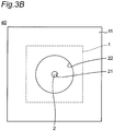
- Fig. 3A is a vertical sectional view showing a configuration of a pressure sensor unit 40 according to a first embodiment and Fig. 3B is a bottom view of the pressure sensor unit 40 in Fig. 3A .
- an MEMS pressure sensor 1 is fixed, by a plurality of solder balls 31, to a center part of a lower side of a square plate-shaped dielectric substrate (may be a semiconductor substrate) 10 with a thickness of t1 and a width of d4 as a dielectric substance made of, for example, glass or epoxy.
- a space 30 is formed to be as large as a thickness of the solder balls 31.
- the MEMS pressure sensor 1 has a square plate-shape with, for example, a width of d3 and has a diaphragm 2 provided in a center part thereof, which is a pressure detection surface 2a having, for example, a round or oval shape.
- the diaphragm 2 On the side of a surface 2b opposed to the pressure detection surface 2a of the diaphragm 2, the above space 30 is formed.
- the diaphragm 2 has a thickness smaller than a thickness t2 of the MEMS pressure sensor 1 in proximity of an upper most part of the MEMS pressure sensor 1, and has a space 21, which is, for example, a tubular or oval tubular hole formed on a lower side of the diaphragm 2.
- the space 21 is sealed against the diaphragm 2 and has a lower side direction opened, so that the space 21 and the space 30 fail to communicate with each other.
- the MEMS pressure sensor 1 which has the space 21 with the height of t2 provided on the side of the pressure detection surface 2a of the diaphragm 2, detects a pressure using the pressure detection surface 2a facing the space 21, and outputs an electrical signal corresponding to the detected pressure via a cable 41 inserted through the dielectric substrate 10.
- a pad 11 with the thickness t3 which is, for example, a double-sided adhesive sheet, is adhered, the pad 11 supporting the MEMS pressure sensor 1 and the dielectric substrate 10.
- support by the pad 11 is realized by a bottom surface 11b of a space in a center part of an upper part thereof with a thickness (t3 to t4) (the center part having a hole of a downward space 22 to be described later).
- the pad 11 has a bottom surface 11a thereof placed on and in contact with a part under measurement which is, for example, a radial artery part 7 of a wrist 8 of a person under measurement (See Fig. 5 ) and has the space 22, which is a through hole communicating with the space 21 in the center part of the pad 11 and having a size in a direction parallel to the pressure detection surface 2a and larger than the space 21.
- the space 21 and the space 22 have bottom surfaces substantially parallel to, for example, the pressure detection surface 2a of the diaphragm 2 and have, for example, substantially tubular or oval tubular shapes coaxial to each other, or polygonal shapes such as a square, rectangular shapes and the like.
- the bottom surface of the space 22 is configured to have a diameter d2 larger than a diameter d 1 of the bottom surface of the space 21.
- pressure sensor unit 40 When thus configured pressure sensor unit 40 is placed on and in contact with, for example, a part under measurement which is the radial artery part 7 of the wrist 8 of a person under measurement (See Fig. 5 ), the space 21 and the space 22 are sealed to be a sealed space, so that a pressure of the part under measurement is transmitted to the diaphragm 2 of the MEMS pressure sensor 1 via the space 21 and the space 22, and the MEMS pressure sensor 1 detects the pressure. A pressure detection signal of the MEMS pressure sensor 1 is outputted via the cable 41.
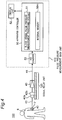
- Fig. 4 is a block diagram showing a configuration of a pulse pressure measuring system 100 using the pressure sensor unit 40 in Fig. 3A .
- the pressure detection signal from the pressure sensor unit 40 is input to a signal amplifier 43 of a signal relay unit 120 via the cable 41, and connectors 42a and 42b, the pressure sensor unit 40 being placed such that the space 22 of the pressure sensor unit 40 is close to, for example, the radial artery part 7 of the person under measurement 6 so as to be able to detect a pressure.
- the signal amplifier 43 amplifies the input pressure detection signal and inputs the amplified signal to an A/D converter 53 of a pulse pressure measurement main unit 110 via a cable 44.
- the pulse pressure measurement main unit 110 is configured with an apparatus controller 50 formed of, for example, a digital computer and having a blood vessel pulse pressure measurement processing module 51 and an internal memory 50m; a display unit 52 such as, for example, a liquid crystal display; and the A/D converter 53.
- the A/D converter 53 outputs the input pressure detection signal to the apparatus controller 50 after A/D converting the same into digital data.
- the apparatus controller 50 By executing processing of the blood vessel pulse pressure measurement processing module 51, the apparatus controller 50 converts the digital data of the pressure detection signal into a pulse pressure value by using a signal level to a pressure value correction table (indicative of a relationship between an electrical signal level of the pressure detection signal and a pressure value) measured and stored in advance in the internal memory 50m, and outputs the obtained value to the display unit 52 to display the same. In this case, the apparatus controller 50 calculates a blood vessel pulse wave signal by executing the above blood vessel pulse pressure measurement processing in real time to display the same on the display unit 52.
- a pressure value correction table indicative of a relationship between an electrical signal level of the pressure detection signal and a pressure value
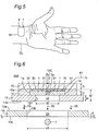
- Fig. 5 is a perspective view showing the pressure sensor unit 40 in Fig. 3A when the pressure sensor unit 40 is attached to the radial artery part 7 of a person under measurement 6. As is clear from Fig. 5 , the pressure sensor unit 40 is attached to the radial artery part 7 of the person under measurement 6 to measure a pulse pressure.
- the inventors have made samples of the pressure sensor unit 40 and the pulse pressure measuring system 100 according to the embodiment A design result was obtained that the diameter d1 of the diaphragm 2 (the space 21) of the MEMS pressure sensor 1 in the pressure sensor unit 40 was most preferably on the order of 1 mm.
- the length d4 of one side of each of the dielectric substrate 10 and the pad 11 was set to be 3 to 4 mm and the diameter d2 of the space 22 was set to be 2 to 3 mm.
- the thickness t2 of the MEMS pressure sensor 1 was 400 ⁇ m and a thickness of a lower portion of the pad 11 was 0.5 to 1 mm.
- a blood vessel needs to be positioned within a range of 1 mm, which is the diameter d1 of the diaphragm 2 of the MEMS pressure sensor 1, and when the position deviates, no pulse pressure can be detected.
- provision of the space 22 enables a pulse pressure to be reliably detected even when the diaphragm 2 of the MEMS pressure sensor 1 deviates on the order of 1 to 1.5 mm as long as the deviation is within a range of the space 22.
- the MEMS pressure sensing apparatus of the present embodiment enables detection of a pulse pressure without applying a pressure, bloodless blood pressure pulse wave measurement can be conducted for a long period of time. Additionally, it is possible, in a manner similar to that of the conventional example, to measure a blood pressure of a person under measurement using the measurement method of Patent Document 2.
- the space 21 and the space 22 are sealed to be a sealed space, so that a pressure of the part under measurement is transmitted to the diaphragm 2 of the MEMS pressure sensor 1 via the space 21 and the space 22, and the MEMS pressure sensor 1 detects the pressure. Accordingly, even when the position of the MEMS pressure sensor 1 deviates from a measurement position, it is possible to precisely measure a pressure of the part under measurement. Additionally, since it is not necessary to apply a pressure to the part under measurement, it is possible to measure, for example, a bloodless blood pressure pulse wave for a long period of time.
- Fig. 6 is a vertical sectional view showing a configuration of a pressure sensor unit 40A according an embodiment of the present invention. Referring to Fig. 6 , the pressure sensor unit 40A according to the second embodiment is different from the pressure sensor unit 40 in Fig. 3A in the following points.
- Step A First of all, the film sheet 13 is adhered to a position of the radial artery part 7 (preferably, a part first confirmed and marked as a position at which pulse can be taken).
- the film sheet 13 is positioned and adhered such that a bonding lower surface 13b of the film sheet 13 is bonded to a surface of skin of the radial artery part 7, and a center part of the pressure sensing cavity hole 13h of the film sheet 13 is located at the radial artery part 7.
- Step B Subsequently, to an upper surface 13a of the film sheet 13, the film sheet 12 of the pressure sensor unit 40A is adhered.
- the pressure sensor unit 40A having the film sheet 12 is positioned such that the mark 10C is located at the center part of the pressure sensing cavity hole 13h, i.e., such that a center part of the pressure sensing cavity hole 12h of the film sheet 12 is located at the center part of the pressure sensing cavity hole 13h.
- Fig. 7 is a vertical sectional view showing the pressure sensor unit 40A in Fig. 6 when the pressure sensor unit 40A is attached to the radial artery part 7 of a person under measurement 6. Specifically, Fig. 7 shows a state after the above Step B.
- a two-stage adhering step enables the sealed spaces 21, 22, and 23 to be reliably formed for sensing pulsation by the MEMS sensor.
- the pressure sensor unit 40A of the second embodiment when the pressure sensor unit 40A is placed on a part under measurement, the spaces 21, 22, and 23 are sealed to be a sealed space, so that a pressure of the part under measurement is transmitted to a diaphragm 2 of an MEMS pressure sensor 1 via the spaces 21, 22, and 23, and the MEMS pressure sensor 1 detects the pressure. Accordingly, even when the position of the MEMS pressure sensor 1 deviates from a measurement position, it is possible to precisely measure the pressure of the part under measurement. Additionally, since it is not necessary to apply a pressure to the part under measurement, it is possible to measure, for example, a bloodless blood pressure pulse wave for a long period of time.
- Fig. 8 is a photograph of signal waveforms of an experimental result obtained when a pulse wave signal of a radial artery part is measured using the MEMS pressure sensor 220 according to the conventional example in Fig. 1 , where Fig. 8(a) shows an output signal waveform of the MEMS pressure sensor 220, and Fig. 8(b) shows a signal waveform obtained when the output signal is passed through a low pass filter.
- Fig. 9 is a photograph of signal waveforms of an experimental result obtained when a pulse wave signal of a radial artery part is measured using the MEMS pressure sensor unit 40A according to the second embodiment in Fig. 6 , where Fig. 9(a) shows an output signal waveform of the MEMS pressure sensor unit 40A, and Fig. 9(b) shows a signal waveform obtained when the output signal is passed through a low pass filter.
- both an output waveform of the sensor and a signal waveform obtained after passing through a low pass filter can be measured with an S/N ratio drastically increased as compared with a signal waveform of a conventional example.
- the present invention is not limited thereto and is applicable to a pressure measuring system and a blood pressure measuring system, that measure a pulse pressure of other animal than a human being and a common pressure.
- the pressure sensor units 40 and 40A can be used as a pressure sensing apparatus to detect not only a pulse pressure of a blood vessel but also a pulse pressure of other animal than a human being and detect a common pressure.
- shapes of the spaces 21, 22, and 23 formed by the respective cavity holes may be not only tubular but also oval tubular.
- the MEMS pressure sensing apparatus when the MEMS pressure sensing apparatus is placed on a part under measurement to have a sealed space, a pressure of the part under measurement is transmitted to the diaphragm of the MEMS pressure sensor via two or three spaces, so that the MEMS pressure sensor detects a pressure. Accordingly, even when a position of the MEMS pressure sensor deviates from a measurement position, it is possible to precisely measure a pressure of the part under measurement. Additionally, since it is unnecessary to apply a pressure to the part under measurement, a bloodless blood pressure pulse wave can be measured for a long period of time.
- the present invention enables the sensing portion of the MEMS pressure sensor to be positioned at an area of a radial artery part more precisely as compared with a conventional example, and an S/N ratio can be obtained which is higher than that of the conventional example.
Landscapes
- Health & Medical Sciences (AREA)
- Life Sciences & Earth Sciences (AREA)
- Physics & Mathematics (AREA)
- Cardiology (AREA)
- Surgery (AREA)
- Public Health (AREA)
- Biomedical Technology (AREA)
- Heart & Thoracic Surgery (AREA)
- Medical Informatics (AREA)
- Molecular Biology (AREA)
- Pathology (AREA)
- Animal Behavior & Ethology (AREA)
- General Health & Medical Sciences (AREA)
- Engineering & Computer Science (AREA)
- Veterinary Medicine (AREA)
- Biophysics (AREA)
- Physiology (AREA)
- Vascular Medicine (AREA)
- General Physics & Mathematics (AREA)
- Ophthalmology & Optometry (AREA)
- Measuring Pulse, Heart Rate, Blood Pressure Or Blood Flow (AREA)
Claims (7)
- Appareil de détection de pression MEMS, comprenant :un capteur de pression MEMS (1), dans lequel,le capteur de pression MEMS (1) comprendun premier espace (21) sur un côté d'une surface de détection de pression d'un diaphragme (2), dans lequel le côté de la surface de détection de pression est tourné vers la partie à mesurer,le diaphragme (2) pour détecter une pression au moyen de la surface de détection de pression tournée vers le premier espace (21), dans lequelle capteur de pression MEMS (1) est configuré pour délivrer un signal électrique correspondant à la pression détectée ; etune première feuille de film (12) placée entre le capteur de pression MEMS (1) et une partie à mesurer de manière à supporter le capteur de pression MEMS (1), la première feuille de film (12) comprend un deuxième espace (22) communiquant avec le premier espace (21) et présentant une taille dans une direction parallèle à la surface de détection de pression, la taille de la première feuille de film (12) étant plus grande que le premier espace (21),caractérisé en ce quel'appareil de détection de pression MEMS comprend en outre une deuxième feuille de film (13) présentant un troisième espace (23) avec une taille dans une direction parallèle à la surface de détection de pression pour positionner l'appareil de détection de pression MEMS sur la partie à mesurer, la deuxième feuille de film (13) est configurée pour être placée de telle sorte qu'une zone de la partie à mesurer est située dans le troisième espace (23) avant que l'appareil de détection de pression MEMS ne soit placé sur la partie à mesurer, dans lequel le premier espace (21), le deuxième espace (22) et le troisième espace (23) présentent des surfaces de fond sensiblement parallèles à la surface de détection de pression du diaphragme (2), dans lequelle diamètre de la surface de fond du troisième espace (23) est plus grand que le diamètre de la surface de fond du deuxième espace (22), etle diamètre de la surface de fond du deuxième espace (22) est plus grand que le diamètre de la surface de fond du premier espace (21).
- Appareil de détection de pression MEMS selon la revendication 1 configuré de telle sorte que, lorsque l'appareil de détection de pression MEMS est placé sur la partie à mesurer par le biais de la deuxième feuille de film (13), le premier espace (21), le deuxième espace (22) et le troisième espace (23) sont étanchéifiés pour être un espace étanchéifié, de sorte qu'une pression de la partie à mesurer est transmise au diaphragme (2) du capteur de pression MEMS (1) par le biais du premier espace (21), du deuxième espace (22), et du troisième espace (23), et le capteur de pression MEMS (1) détecte la pression.
- Appareil de détection de pression MEMS selon la revendication 1 ou 2, dans lequel les surfaces de fond du premier espace (21), du deuxième espace (22) et du troisième espace (23) présentent des formes sensiblement tubulaires ou tubulaires ovales coaxiales les unes par rapport aux autres.
- Appareil de détection de pression MEMS selon l'une quelconque des revendications 1 à 3, dans lequel les première et deuxième feuilles de film (12, 13) sont des feuilles adhésives, respectivement.
- Système de mesure de pression comprenant :l'appareil de détection de pression MEMS selon l'une quelconque des revendications 1 à 4 ; etune unité de mesure de pression (110) qui calcule une valeur de pression sur la base d'un signal électrique provenant de l'appareil de détection de pression MEMS par rapport à une relation entre un niveau de signal électrique et une valeur de pression mesurée à l'avance, et délivre la valeur de pression calculée.
- Système de mesure de pression selon la revendication 5 configuré de telle sorte que le troisième espace (23) de l'appareil de détection de pression MEMS est prévu pour être proche d'un vaisseau sanguin de la partie à mesurer de manière à être apte à détecter une pression, et dans lequel l'unité de mesure de pression (110) est configurée pour calculer et délivrer une valeur de pression différentielle qui est la valeur de pression.
- Procédé pour positionner un appareil de détection de pression MEMS selon la revendication 1,
caractérisé en ce que
le procédé de positionnement de l'appareil de détection de pression MEMS comprend les étapes de :placement d'une deuxième feuille de film (13) comprenant un troisième espace (23) avec une taille dans une direction parallèle à la surface de détection de pression sur une zone de la partie à mesurer de telle sorte que la zone de la partie à mesurer est située dans le troisième espace (23) ; et par la suite,placement du capteur de pression MEMS (1) présentant la première feuille de film (12) sur la deuxième feuille de film (13) de telle sorte que le deuxième espace (22) est situé dans le troisième espace (23), positionnant ainsi l'appareil de détection de pression MEMS sur la partie à mesurer.
Applications Claiming Priority (2)
| Application Number | Priority Date | Filing Date | Title |
|---|---|---|---|
| JP2015050920 | 2015-03-13 | ||
| PCT/JP2015/084799 WO2016147503A1 (fr) | 2015-03-13 | 2015-12-11 | Capteur de pression mems et son procédé de positionnement |
Publications (3)
| Publication Number | Publication Date |
|---|---|
| EP3270132A1 EP3270132A1 (fr) | 2018-01-17 |
| EP3270132A4 EP3270132A4 (fr) | 2018-10-31 |
| EP3270132B1 true EP3270132B1 (fr) | 2021-04-07 |
Family
ID=56920326
Family Applications (1)
| Application Number | Title | Priority Date | Filing Date |
|---|---|---|---|
| EP15885595.7A Active EP3270132B1 (fr) | 2015-03-13 | 2015-12-11 | Capteur de pression mems et son procédé de positionnement |
Country Status (3)
| Country | Link |
|---|---|
| US (1) | US10582859B2 (fr) |
| EP (1) | EP3270132B1 (fr) |
| WO (1) | WO2016147503A1 (fr) |
Families Citing this family (3)
| Publication number | Priority date | Publication date | Assignee | Title |
|---|---|---|---|---|
| WO2019171028A1 (fr) * | 2018-03-07 | 2019-09-12 | Bae Systems Plc | Système de fusée d'obus |
| KR102751479B1 (ko) * | 2018-07-06 | 2025-01-09 | 삼성전자주식회사 | 생체 정보 측정 장치 및 방법 |
| CA3136043A1 (fr) * | 2019-04-19 | 2020-10-22 | 42 Health Sensor Holdings Ltd | Dispositif de surveillance cardiovasculaire extracorporel |
Citations (1)
| Publication number | Priority date | Publication date | Assignee | Title |
|---|---|---|---|---|
| US20110031566A1 (en) * | 2008-04-03 | 2011-02-10 | Snu R&Db Foundation | Conductive nanomembrane, and mems sensor of using the same |
Family Cites Families (7)
| Publication number | Priority date | Publication date | Assignee | Title |
|---|---|---|---|---|
| JPS5017501B1 (fr) | 1970-03-13 | 1975-06-21 | ||
| BRPI0821411A2 (pt) | 2007-12-20 | 2015-06-16 | Acarix As | Emplastro adesivo para monitorar sinais acústicos. |
| US8230745B2 (en) * | 2008-11-19 | 2012-07-31 | Honeywell International Inc. | Wet/wet differential pressure sensor based on microelectronic packaging process |
| CN104000563A (zh) | 2011-01-24 | 2014-08-27 | 株式会社Act医疗服务 | 血管脉搏波测量系统 |
| JP5766569B2 (ja) * | 2011-09-27 | 2015-08-19 | 株式会社東芝 | 脈波伝播速度計測装置 |
| WO2015170376A1 (fr) * | 2014-05-07 | 2015-11-12 | 株式会社アクトメディカルサービス | Dispositif capteur de pression mems |
| JP6240581B2 (ja) * | 2014-09-24 | 2017-11-29 | 株式会社アドバンテスト | 脈波センサユニット |
-
2015
- 2015-12-11 WO PCT/JP2015/084799 patent/WO2016147503A1/fr not_active Ceased
- 2015-12-11 EP EP15885595.7A patent/EP3270132B1/fr active Active
- 2015-12-11 US US15/557,280 patent/US10582859B2/en active Active
Patent Citations (1)
| Publication number | Priority date | Publication date | Assignee | Title |
|---|---|---|---|---|
| US20110031566A1 (en) * | 2008-04-03 | 2011-02-10 | Snu R&Db Foundation | Conductive nanomembrane, and mems sensor of using the same |
Also Published As
| Publication number | Publication date |
|---|---|
| WO2016147503A1 (fr) | 2016-09-22 |
| EP3270132A4 (fr) | 2018-10-31 |
| EP3270132A1 (fr) | 2018-01-17 |
| US20180055387A1 (en) | 2018-03-01 |
| US10582859B2 (en) | 2020-03-10 |
Similar Documents
| Publication | Publication Date | Title |
|---|---|---|
| EP3943001B1 (fr) | Appareil de mesure de pression sanguine de type tactile | |
| CN103327886B (zh) | 光学测量装置和用于光学测量的方法 | |
| CN103637787B (zh) | 血压实时测量装置以及实时测量脉搏波传输时间差的方法 | |
| EP3270132B1 (fr) | Capteur de pression mems et son procédé de positionnement | |
| CN112190245B (zh) | 血压测量装置 | |
| EP2030564A3 (fr) | Systèmes et procédés de mesure de la pression sanguine systémique implantable | |
| EP3114986A1 (fr) | Appareil et procédé de mesure d'un biosignal | |
| CN109059748B (zh) | 柔性传感器及柔性信号检测装置 | |
| CN103637788B (zh) | 血压实时测量装置 | |
| RU2010150169A (ru) | Картирование по данным с зонда с использованием информации о контакте | |
| WO2020148280A3 (fr) | Dispositif à capteurs multiples pour surveiller la santé | |
| JP5961327B1 (ja) | 睡眠状態モニタリングシステム | |
| CN107847168B (zh) | 脉搏波传感装置 | |
| CN103637789B (zh) | 血压实时测量装置 | |
| JP5401678B2 (ja) | 透析患者用プローブガーゼおよび透析患者用判定器 | |
| JP5937775B1 (ja) | Mems圧力センサとその位置決め方法 | |
| WO2010089893A1 (fr) | Système permettant de mesurer l'onde d'impulsion d'un vaisseau sanguin | |
| CN211381310U (zh) | 振动传感器及脉搏测量系统 | |
| Ziaie et al. | An implantable pressure sensor cuff for tonometric blood pressure measurement | |
| WO2014147553A1 (fr) | Système de surveillance amélioré | |
| JP7088166B2 (ja) | 流体圧力検出装置 | |
| WO2015170376A1 (fr) | Dispositif capteur de pression mems | |
| US20210361931A1 (en) | Component for conducting a fluid having a sensor | |
| CN114754918A (zh) | 具有多个压力感测元件的压力传感器 | |
| JP2017029504A (ja) | 信号変換アダプタ装置及び血管脈波測定システム |
Legal Events
| Date | Code | Title | Description |
|---|---|---|---|
| STAA | Information on the status of an ep patent application or granted ep patent |
Free format text: STATUS: THE INTERNATIONAL PUBLICATION HAS BEEN MADE |
|
| PUAI | Public reference made under article 153(3) epc to a published international application that has entered the european phase |
Free format text: ORIGINAL CODE: 0009012 |
|
| STAA | Information on the status of an ep patent application or granted ep patent |
Free format text: STATUS: REQUEST FOR EXAMINATION WAS MADE |
|
| 17P | Request for examination filed |
Effective date: 20171013 |
|
| AK | Designated contracting states |
Kind code of ref document: A1 Designated state(s): AL AT BE BG CH CY CZ DE DK EE ES FI FR GB GR HR HU IE IS IT LI LT LU LV MC MK MT NL NO PL PT RO RS SE SI SK SM TR |
|
| AX | Request for extension of the european patent |
Extension state: BA ME |
|
| DAV | Request for validation of the european patent (deleted) | ||
| DAX | Request for extension of the european patent (deleted) | ||
| A4 | Supplementary search report drawn up and despatched |
Effective date: 20181002 |
|
| RIC1 | Information provided on ipc code assigned before grant |
Ipc: A61B 5/021 20060101ALI20180925BHEP Ipc: A61B 5/02 20060101ALI20180925BHEP Ipc: A61B 5/00 20060101ALI20180925BHEP Ipc: A61B 5/022 20060101ALI20180925BHEP Ipc: G01L 19/00 20060101AFI20180925BHEP Ipc: A61B 5/024 20060101ALI20180925BHEP |
|
| STAA | Information on the status of an ep patent application or granted ep patent |
Free format text: STATUS: EXAMINATION IS IN PROGRESS |
|
| 17Q | First examination report despatched |
Effective date: 20200414 |
|
| GRAP | Despatch of communication of intention to grant a patent |
Free format text: ORIGINAL CODE: EPIDOSNIGR1 |
|
| STAA | Information on the status of an ep patent application or granted ep patent |
Free format text: STATUS: GRANT OF PATENT IS INTENDED |
|
| INTG | Intention to grant announced |
Effective date: 20201027 |
|
| GRAS | Grant fee paid |
Free format text: ORIGINAL CODE: EPIDOSNIGR3 |
|
| GRAA | (expected) grant |
Free format text: ORIGINAL CODE: 0009210 |
|
| STAA | Information on the status of an ep patent application or granted ep patent |
Free format text: STATUS: THE PATENT HAS BEEN GRANTED |
|
| AK | Designated contracting states |
Kind code of ref document: B1 Designated state(s): AL AT BE BG CH CY CZ DE DK EE ES FI FR GB GR HR HU IE IS IT LI LT LU LV MC MK MT NL NO PL PT RO RS SE SI SK SM TR |
|
| REG | Reference to a national code |
Ref country code: GB Ref legal event code: FG4D |
|
| REG | Reference to a national code |
Ref country code: AT Ref legal event code: REF Ref document number: 1380295 Country of ref document: AT Kind code of ref document: T Effective date: 20210415 Ref country code: CH Ref legal event code: EP |
|
| REG | Reference to a national code |
Ref country code: DE Ref legal event code: R096 Ref document number: 602015067947 Country of ref document: DE |
|
| REG | Reference to a national code |
Ref country code: IE Ref legal event code: FG4D |
|
| REG | Reference to a national code |
Ref country code: LT Ref legal event code: MG9D |
|
| REG | Reference to a national code |
Ref country code: NL Ref legal event code: MP Effective date: 20210407 Ref country code: AT Ref legal event code: MK05 Ref document number: 1380295 Country of ref document: AT Kind code of ref document: T Effective date: 20210407 |
|
| PG25 | Lapsed in a contracting state [announced via postgrant information from national office to epo] |
Ref country code: BG Free format text: LAPSE BECAUSE OF FAILURE TO SUBMIT A TRANSLATION OF THE DESCRIPTION OR TO PAY THE FEE WITHIN THE PRESCRIBED TIME-LIMIT Effective date: 20210707 Ref country code: AT Free format text: LAPSE BECAUSE OF FAILURE TO SUBMIT A TRANSLATION OF THE DESCRIPTION OR TO PAY THE FEE WITHIN THE PRESCRIBED TIME-LIMIT Effective date: 20210407 Ref country code: HR Free format text: LAPSE BECAUSE OF FAILURE TO SUBMIT A TRANSLATION OF THE DESCRIPTION OR TO PAY THE FEE WITHIN THE PRESCRIBED TIME-LIMIT Effective date: 20210407 Ref country code: FI Free format text: LAPSE BECAUSE OF FAILURE TO SUBMIT A TRANSLATION OF THE DESCRIPTION OR TO PAY THE FEE WITHIN THE PRESCRIBED TIME-LIMIT Effective date: 20210407 Ref country code: NL Free format text: LAPSE BECAUSE OF FAILURE TO SUBMIT A TRANSLATION OF THE DESCRIPTION OR TO PAY THE FEE WITHIN THE PRESCRIBED TIME-LIMIT Effective date: 20210407 Ref country code: LT Free format text: LAPSE BECAUSE OF FAILURE TO SUBMIT A TRANSLATION OF THE DESCRIPTION OR TO PAY THE FEE WITHIN THE PRESCRIBED TIME-LIMIT Effective date: 20210407 |
|
| PG25 | Lapsed in a contracting state [announced via postgrant information from national office to epo] |
Ref country code: SE Free format text: LAPSE BECAUSE OF FAILURE TO SUBMIT A TRANSLATION OF THE DESCRIPTION OR TO PAY THE FEE WITHIN THE PRESCRIBED TIME-LIMIT Effective date: 20210407 Ref country code: RS Free format text: LAPSE BECAUSE OF FAILURE TO SUBMIT A TRANSLATION OF THE DESCRIPTION OR TO PAY THE FEE WITHIN THE PRESCRIBED TIME-LIMIT Effective date: 20210407 Ref country code: NO Free format text: LAPSE BECAUSE OF FAILURE TO SUBMIT A TRANSLATION OF THE DESCRIPTION OR TO PAY THE FEE WITHIN THE PRESCRIBED TIME-LIMIT Effective date: 20210707 Ref country code: PT Free format text: LAPSE BECAUSE OF FAILURE TO SUBMIT A TRANSLATION OF THE DESCRIPTION OR TO PAY THE FEE WITHIN THE PRESCRIBED TIME-LIMIT Effective date: 20210809 Ref country code: PL Free format text: LAPSE BECAUSE OF FAILURE TO SUBMIT A TRANSLATION OF THE DESCRIPTION OR TO PAY THE FEE WITHIN THE PRESCRIBED TIME-LIMIT Effective date: 20210407 Ref country code: GR Free format text: LAPSE BECAUSE OF FAILURE TO SUBMIT A TRANSLATION OF THE DESCRIPTION OR TO PAY THE FEE WITHIN THE PRESCRIBED TIME-LIMIT Effective date: 20210708 Ref country code: IS Free format text: LAPSE BECAUSE OF FAILURE TO SUBMIT A TRANSLATION OF THE DESCRIPTION OR TO PAY THE FEE WITHIN THE PRESCRIBED TIME-LIMIT Effective date: 20210807 Ref country code: LV Free format text: LAPSE BECAUSE OF FAILURE TO SUBMIT A TRANSLATION OF THE DESCRIPTION OR TO PAY THE FEE WITHIN THE PRESCRIBED TIME-LIMIT Effective date: 20210407 |
|
| REG | Reference to a national code |
Ref country code: DE Ref legal event code: R097 Ref document number: 602015067947 Country of ref document: DE |
|
| PG25 | Lapsed in a contracting state [announced via postgrant information from national office to epo] |
Ref country code: SM Free format text: LAPSE BECAUSE OF FAILURE TO SUBMIT A TRANSLATION OF THE DESCRIPTION OR TO PAY THE FEE WITHIN THE PRESCRIBED TIME-LIMIT Effective date: 20210407 Ref country code: SK Free format text: LAPSE BECAUSE OF FAILURE TO SUBMIT A TRANSLATION OF THE DESCRIPTION OR TO PAY THE FEE WITHIN THE PRESCRIBED TIME-LIMIT Effective date: 20210407 Ref country code: DK Free format text: LAPSE BECAUSE OF FAILURE TO SUBMIT A TRANSLATION OF THE DESCRIPTION OR TO PAY THE FEE WITHIN THE PRESCRIBED TIME-LIMIT Effective date: 20210407 Ref country code: EE Free format text: LAPSE BECAUSE OF FAILURE TO SUBMIT A TRANSLATION OF THE DESCRIPTION OR TO PAY THE FEE WITHIN THE PRESCRIBED TIME-LIMIT Effective date: 20210407 Ref country code: CZ Free format text: LAPSE BECAUSE OF FAILURE TO SUBMIT A TRANSLATION OF THE DESCRIPTION OR TO PAY THE FEE WITHIN THE PRESCRIBED TIME-LIMIT Effective date: 20210407 Ref country code: RO Free format text: LAPSE BECAUSE OF FAILURE TO SUBMIT A TRANSLATION OF THE DESCRIPTION OR TO PAY THE FEE WITHIN THE PRESCRIBED TIME-LIMIT Effective date: 20210407 Ref country code: ES Free format text: LAPSE BECAUSE OF FAILURE TO SUBMIT A TRANSLATION OF THE DESCRIPTION OR TO PAY THE FEE WITHIN THE PRESCRIBED TIME-LIMIT Effective date: 20210407 |
|
| PLBE | No opposition filed within time limit |
Free format text: ORIGINAL CODE: 0009261 |
|
| STAA | Information on the status of an ep patent application or granted ep patent |
Free format text: STATUS: NO OPPOSITION FILED WITHIN TIME LIMIT |
|
| 26N | No opposition filed |
Effective date: 20220110 |
|
| PG25 | Lapsed in a contracting state [announced via postgrant information from national office to epo] |
Ref country code: IS Free format text: LAPSE BECAUSE OF FAILURE TO SUBMIT A TRANSLATION OF THE DESCRIPTION OR TO PAY THE FEE WITHIN THE PRESCRIBED TIME-LIMIT Effective date: 20210807 Ref country code: AL Free format text: LAPSE BECAUSE OF FAILURE TO SUBMIT A TRANSLATION OF THE DESCRIPTION OR TO PAY THE FEE WITHIN THE PRESCRIBED TIME-LIMIT Effective date: 20210407 |
|
| PG25 | Lapsed in a contracting state [announced via postgrant information from national office to epo] |
Ref country code: MC Free format text: LAPSE BECAUSE OF FAILURE TO SUBMIT A TRANSLATION OF THE DESCRIPTION OR TO PAY THE FEE WITHIN THE PRESCRIBED TIME-LIMIT Effective date: 20210407 Ref country code: IT Free format text: LAPSE BECAUSE OF FAILURE TO SUBMIT A TRANSLATION OF THE DESCRIPTION OR TO PAY THE FEE WITHIN THE PRESCRIBED TIME-LIMIT Effective date: 20210407 |
|
| REG | Reference to a national code |
Ref country code: CH Ref legal event code: PL |
|
| REG | Reference to a national code |
Ref country code: BE Ref legal event code: MM Effective date: 20211231 |
|
| PG25 | Lapsed in a contracting state [announced via postgrant information from national office to epo] |
Ref country code: LU Free format text: LAPSE BECAUSE OF NON-PAYMENT OF DUE FEES Effective date: 20211211 Ref country code: IE Free format text: LAPSE BECAUSE OF NON-PAYMENT OF DUE FEES Effective date: 20211211 |
|
| PG25 | Lapsed in a contracting state [announced via postgrant information from national office to epo] |
Ref country code: BE Free format text: LAPSE BECAUSE OF NON-PAYMENT OF DUE FEES Effective date: 20211231 |
|
| PG25 | Lapsed in a contracting state [announced via postgrant information from national office to epo] |
Ref country code: LI Free format text: LAPSE BECAUSE OF NON-PAYMENT OF DUE FEES Effective date: 20211231 Ref country code: CH Free format text: LAPSE BECAUSE OF NON-PAYMENT OF DUE FEES Effective date: 20211231 |
|
| PG25 | Lapsed in a contracting state [announced via postgrant information from national office to epo] |
Ref country code: HU Free format text: LAPSE BECAUSE OF FAILURE TO SUBMIT A TRANSLATION OF THE DESCRIPTION OR TO PAY THE FEE WITHIN THE PRESCRIBED TIME-LIMIT; INVALID AB INITIO Effective date: 20151211 |
|
| PG25 | Lapsed in a contracting state [announced via postgrant information from national office to epo] |
Ref country code: CY Free format text: LAPSE BECAUSE OF FAILURE TO SUBMIT A TRANSLATION OF THE DESCRIPTION OR TO PAY THE FEE WITHIN THE PRESCRIBED TIME-LIMIT Effective date: 20210407 |
|
| PG25 | Lapsed in a contracting state [announced via postgrant information from national office to epo] |
Ref country code: MK Free format text: LAPSE BECAUSE OF FAILURE TO SUBMIT A TRANSLATION OF THE DESCRIPTION OR TO PAY THE FEE WITHIN THE PRESCRIBED TIME-LIMIT Effective date: 20210407 |
|
| PG25 | Lapsed in a contracting state [announced via postgrant information from national office to epo] |
Ref country code: MT Free format text: LAPSE BECAUSE OF FAILURE TO SUBMIT A TRANSLATION OF THE DESCRIPTION OR TO PAY THE FEE WITHIN THE PRESCRIBED TIME-LIMIT Effective date: 20210407 |
|
| PG25 | Lapsed in a contracting state [announced via postgrant information from national office to epo] |
Ref country code: TR Free format text: LAPSE BECAUSE OF FAILURE TO SUBMIT A TRANSLATION OF THE DESCRIPTION OR TO PAY THE FEE WITHIN THE PRESCRIBED TIME-LIMIT Effective date: 20210407 |
|
| PGFP | Annual fee paid to national office [announced via postgrant information from national office to epo] |
Ref country code: GB Payment date: 20251114 Year of fee payment: 11 |
|
| PGFP | Annual fee paid to national office [announced via postgrant information from national office to epo] |
Ref country code: FR Payment date: 20251103 Year of fee payment: 11 |
|
| PGFP | Annual fee paid to national office [announced via postgrant information from national office to epo] |
Ref country code: DE Payment date: 20260119 Year of fee payment: 11 |