EP3270363A1 - Verfahren zur herstellung eines drahtlosen flurförderersteuerungssystems - Google Patents
Verfahren zur herstellung eines drahtlosen flurförderersteuerungssystems Download PDFInfo
- Publication number
- EP3270363A1 EP3270363A1 EP16179520.8A EP16179520A EP3270363A1 EP 3270363 A1 EP3270363 A1 EP 3270363A1 EP 16179520 A EP16179520 A EP 16179520A EP 3270363 A1 EP3270363 A1 EP 3270363A1
- Authority
- EP
- European Patent Office
- Prior art keywords
- floor conveyor
- remote control
- pairing
- communication protocol
- wireless
- Prior art date
- Legal status (The legal status is an assumption and is not a legal conclusion. Google has not performed a legal analysis and makes no representation as to the accuracy of the status listed.)
- Withdrawn
Links
- 238000000034 method Methods 0.000 title claims abstract description 54
- 238000004891 communication Methods 0.000 claims description 50
- 238000005516 engineering process Methods 0.000 claims description 13
- 230000005540 biological transmission Effects 0.000 description 5
- FGUUSXIOTUKUDN-IBGZPJMESA-N C1(=CC=CC=C1)N1C2=C(NC([C@H](C1)NC=1OC(=NN=1)C1=CC=CC=C1)=O)C=CC=C2 Chemical compound C1(=CC=CC=C1)N1C2=C(NC([C@H](C1)NC=1OC(=NN=1)C1=CC=CC=C1)=O)C=CC=C2 FGUUSXIOTUKUDN-IBGZPJMESA-N 0.000 description 2
- YTAHJIFKAKIKAV-XNMGPUDCSA-N [(1R)-3-morpholin-4-yl-1-phenylpropyl] N-[(3S)-2-oxo-5-phenyl-1,3-dihydro-1,4-benzodiazepin-3-yl]carbamate Chemical compound O=C1[C@H](N=C(C2=C(N1)C=CC=C2)C1=CC=CC=C1)NC(O[C@H](CCN1CCOCC1)C1=CC=CC=C1)=O YTAHJIFKAKIKAV-XNMGPUDCSA-N 0.000 description 2
- 230000006978 adaptation Effects 0.000 description 2
- 230000003993 interaction Effects 0.000 description 2
- 230000002349 favourable effect Effects 0.000 description 1
- HDDSHPAODJUKPD-UHFFFAOYSA-N fenbendazole Chemical compound C1=C2NC(NC(=O)OC)=NC2=CC=C1SC1=CC=CC=C1 HDDSHPAODJUKPD-UHFFFAOYSA-N 0.000 description 1
- 230000000977 initiatory effect Effects 0.000 description 1
- 238000005007 materials handling Methods 0.000 description 1
- 238000005457 optimization Methods 0.000 description 1
- 229940092174 safe-guard Drugs 0.000 description 1
- 230000000153 supplemental effect Effects 0.000 description 1
Images


Classifications
-
- G—PHYSICS
- G08—SIGNALLING
- G08C—TRANSMISSION SYSTEMS FOR MEASURED VALUES, CONTROL OR SIMILAR SIGNALS
- G08C17/00—Arrangements for transmitting signals characterised by the use of a wireless electrical link
- G08C17/02—Arrangements for transmitting signals characterised by the use of a wireless electrical link using a radio link
-
- G—PHYSICS
- G08—SIGNALLING
- G08C—TRANSMISSION SYSTEMS FOR MEASURED VALUES, CONTROL OR SIMILAR SIGNALS
- G08C2201/00—Transmission systems of control signals via wireless link
- G08C2201/20—Binding and programming of remote control devices
Definitions
- the present invention relates to a method of preparing a wireless floor conveyor control system according to claim 1, a floor conveyor remote control system according to claim 8 and a first and a second computer readable software according to claim 12.
- the document EP2079065 A2 describes a method of synchronizing a transmitter and a receiver in a supplemental remote control system for a materials handling vehicle.
- the object of the present invention is achieved by a method of preparing a wireless floor conveyor remote control system comprising a floor conveyor and a wireless floor conveyor remote control both comprising a respective transceiver with a respective pairing antenna device, comprising the steps of:
- This method will simplify the pairing of a floor conveyor to a remote control by using the distance between the floor conveyor and the remote control as a determining factor for the pairing sequence, and the method as a whole.
- a floor conveyor remote control system comprising a floor conveyor and a wireless floor conveyor remote control
- the floor conveyor comprises, a transceiver, a paring antenna device and a control unit
- the remote control comprises transceiver, a pairing antenna device and a control unit
- the transceivers are arranged such that such that radio signals cannot be transmitted further than 20 cm, preferably at most 15 cm, most preferably at most 10 cm, even more preferred at most 5 cm, most preferred at most 2-4 cm, by means of pairing antenna technology and a pairing communication protocol controlled by respective control unit, wherein the transceivers of the floor conveyor and the remote control are able to execute the method according to the above.
- the present disclosure relates to a method of pairing a wireless floor conveyor remote control to a floor conveyor. Pairing means in the context of the disclosure to permit a floor conveyor to be controlled by a particular wireless floor conveyer remote control, and no other wireless floor conveyor remote control.
- the wireless floor conveyor remote control is operable with a floor conveyor for controlling the functions of the floor conveyor.
- the function that is most relevant is the repositioning of the floor conveyor at order picking operations.
- the operator will step off the floor conveyor and walk up to the goods that are to be picked. In that situation it is of interest for the operator to reposition the floor conveyor without going back to the floor conveyor. In this situation a short repositioning of the floor conveyor by means of a wireless floor conveyor remote control is of great help and increases the efficiency of the order picker operation.
- a floor conveyor can be any floor conveyor that is suitable for remote control.
- Figure 4 discloses an order picker truck, figure 5 a reach truck, and figure 6 a stacker truck. But the present disclosure are not limited for these particular floor conveyors, also any type of tow tractor could be used. This means that a load carrier in the form of forks is not essential for the present disclosure.
- the present disclosure is related to material handling vehicles that mainly operate inside a warehouse. In general it is to be applied to electrically powered floor conveyors. It is preferred that the floor conveyor can detect and avoid objects when operated by means of the remote control.
- the remote control is preferably a simple device that can control start and forward travel, and not make more advanced travel manoeuvres.
- the sensor device is preferably a centrally positioned laser sensor.
- the sensor device is preferably able to detect objects by means of a plane that is angled to the horizontal plane.
- the sensor device preferably transmits the sensor data to a control unit of the floor conveyor, wherein the control unit is operable to control the travel function of the floor conveyor.
- the travel function of the floor conveyor is to be understood to mean the motor, and brakes, and other devices needed for driving the floor conveyor.
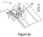
- the floor conveyor 2 Figures 4-6 , of the present disclosure comprises a transceiver 3.
- the transceiver 3 in general comprises an emitter and a receiver.
- the floor conveyor 2 comprises further a control unit 4 of the transceiver 3.
- a pairing antenna device 5 is also comprised in the floor conveyor 2.
- floor conveyors 2 comprise a control handle 7 or steering controls 7a.
- floor conveyors also comprise a main control unit 8.
- the control handle 7 or the steering controls 7a are used by the operator for operating the floor conveyor 2 in material handling situations as known to the person skilled in the art.
- the transceiver control unit 4 can be incorporated with the main control unit 8, not disclosed in the Figures. There is also an internal bus and a travel motor etc.
- the floor conveyor further comprises in general an operation protocol antenna device 6. It is possible to use the pairing antenna device 5 for operation protocol radio transmissions, but in general a further antenna device is preferable for easy adaptation to the operation protocol transmission.
- Figure 4a discloses an example of a Floor conveyor 2 with a sensor device 40 for detecting objects as a part of a remote control system 1.
- the wireless floor conveyor remote control 20 of the present disclosure comprises a pairing antenna device 26, and a control unit 24, and a transceiver 23.
- the wireless floor conveyor remote control 20 further comprises in general an operation protocol antenna device 26. It is possible to use the pairing antenna device 25 for operation protocol radio transmissions, but in general a further antenna device 26 is preferable for easy adaptation to the operation protocol transmission.
- the remote control 20 also comprises an operator interaction device 27, preferably a button.
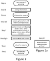
- the present disclosure refers to a method of preparing a floor conveyor remote control system, see Figure 1 .
- the system requires a floor conveyor and a wireless floor conveyor remote control with a respective transceiver and a respective pairing antenna device.
- the method involves the steps of:
- the pairing sequence is ended by step j.
- the complete method is ended by step k. and after this the floor conveyor and the remote control can operate together as a paired system.
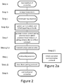
- a step j1 can be comprised:
- step j1. is primarily to save energy, and not continuously run the pairing sequence itself.
- the remote control and the floor conveyor are still operable with each other.
- the pairing antennas of the transceivers are arranged in cooperation with the pairing communication protocol such that no standing wave can be achieved, preferably by arranging the pairing antennas with a length that mismatch with the radio wave length ⁇ of the pairing communication protocol.
- This explains how the pairing can be limited to the distances that are required for the method. It is of course important that the pairing radio signals are not received by a further floor conveyor for example. This could lead to serious consequences in the warehouse.
- the mismatch in general means that no standing wave is to be achieved. Generally a standing wave is desired by a transmitter/transceiver in order to safe guard a good distribution range of the radio waves. In this case the desire is the opposite.
- the pairing protocol e.g. wave length ⁇
- the technology used could be Near Field Communication or NFC.
- the pairing of the floor conveyor and the remote control is ended after a predetermined time t of inactivity of the floor conveyor and/or the remote control or the pairing is ended if a new pairing sequence is initiated, after pairing is ended the floor conveyor is no longer associated with the remote control.
- the method further comprises the step of:
- the pairing radio protocol itself is not particularly well adapted for remote controlling the floor conveyor over a longer distance for reasons given above.
- the initiation of the operation communication protocol provides for a better operation, when using the remote control. It is thinkable that the operation communication protocol uses the pairing antenna devices of the floor conveyor. By having the operation communication protocol better adapted to the pairing antenna devices a much further range is achieved, than the limit for the pairing sequence.
- On preferred technology for this is Bluetooth, but other radio protocols is thinkable. Bluetooth is well suited as it is very energy efficient.
- respective operation antenna devices are used by the operation protocol. These antenna devices can be optimized in a favourable manner for the best function of the operation radio protocol.
- the operation communication protocol must be able to communicate at distances above 5 meters, for example above 10 meters. However it is not desired that the operation radio protocol can communicate over 100 meters.
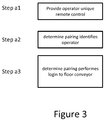
- step a1 is performed already before step a.
- step a2 could be executed after step f.
- Step a3 could be executed after step j.
- a remote control system 1 comprising a floor conveyor 2 and a wireless floor conveyor remote control 20, wherein the floor conveyor 20 comprises, a transceiver 3, a paring antenna device 5 and a control unit 4, wherein the remote control 20 comprises transceiver 23, a pairing antenna device 25 and a control unit 24, wherein the transceivers 3, 23 are arranged such that such that radio signals cannot be transmitted further than 20 cm, preferably at most 15 cm, most preferably at most 10 cm, even more preferred at most 5 cm, most preferred at most 2-4 cm, by means of pairing antenna technology and a pairing communication protocol controlled by respective control unit 4, 24, wherein the transceivers 3, 23 of the floor conveyor 2 and the remote control 20 are able to execute the method according to any described methods above.
- the smallest part of the disclosed system is one floor conveyor 2 and one wireless floor conveyor remote control 20
- the floor conveyor 20 needs of course to be adapted with a transceiver and respective antenna device.
- the control unit itself should be understood as discussed above to be either a particular transceiver control unit 4 or the control unit 4 is incorporated into the main control unit 8 of the floor conveyor 2.
- the disclosure relates to a remote control system 1 according to the above wherein, the pairing antenna devices 5, 25 of the transceivers 3, 23 are arranged together with the pairing communication protocol such that no standing wave can be achieved, preferably by arranging the pairing antenna devices 5, 25 with a length that mismatch with the radio wave length ⁇ . This is a convenient way of achieving the desired range of the pairing operation.
- the disclosure relates to a floor conveyor remote control system 1 according to the above, wherein the floor conveyor 2 and the remote control 20 comprise a further communication protocol, that can be initiated after the pairing communication protocol, wherein the further communication protocol is an operation communication protocol arranged such that it is able to transmit operation signals over at least a distance of 5 meters, such that the wireless remote control 20 and floor conveyor 2 are able to execute the method according to the above.
- the operation communication protocol is based on Bluetooth technology.
- This further operation communication protocol is more optimal for performing the operation of the floor conveyor 1 as it can operate outside the very limited range of the pairing protocol.
- Bluetooth is a preferred protocol of communication. A distance of 5 meters is at least desirable, but above 10 meters is better, however not longer than 100 meters of communication is desired for the operation communication protocol.
- the disclosure relates to a floor conveyor remote control system 1 according to the above, wherein the floor conveyor 2 and the remote control 20 comprise dedicated operation antenna devices 6, 26, different from the pairing antenna devices 5, 25.
- a dedicated operation antenna device provides for the possibility of a better optimization of the operative communication.
- the disclosure also relates to a first computer readable software that when stored on a control unit of a floor conveyor and a second computer readable software that when stored on a control unit of a wireless floor conveyor remote control are able to in cooperation execute the method according to any of the method steps described above. It must be understood that step a1 is executed by dedicating particular codes as identification of a person. Thus the software will need to store the codes in the control unit of the floor conveyor, and also optionally in the remote control. That is in order to provide a dedicated remote control.
Landscapes
- Engineering & Computer Science (AREA)
- Computer Networks & Wireless Communication (AREA)
- Physics & Mathematics (AREA)
- General Physics & Mathematics (AREA)
- Control Of Position, Course, Altitude, Or Attitude Of Moving Bodies (AREA)
Priority Applications (1)
| Application Number | Priority Date | Filing Date | Title |
|---|---|---|---|
| EP16179520.8A EP3270363A1 (de) | 2016-07-14 | 2016-07-14 | Verfahren zur herstellung eines drahtlosen flurförderersteuerungssystems |
Applications Claiming Priority (1)
| Application Number | Priority Date | Filing Date | Title |
|---|---|---|---|
| EP16179520.8A EP3270363A1 (de) | 2016-07-14 | 2016-07-14 | Verfahren zur herstellung eines drahtlosen flurförderersteuerungssystems |
Publications (1)
| Publication Number | Publication Date |
|---|---|
| EP3270363A1 true EP3270363A1 (de) | 2018-01-17 |
Family
ID=56801353
Family Applications (1)
| Application Number | Title | Priority Date | Filing Date |
|---|---|---|---|
| EP16179520.8A Withdrawn EP3270363A1 (de) | 2016-07-14 | 2016-07-14 | Verfahren zur herstellung eines drahtlosen flurförderersteuerungssystems |
Country Status (1)
| Country | Link |
|---|---|
| EP (1) | EP3270363A1 (de) |
Cited By (3)
| Publication number | Priority date | Publication date | Assignee | Title |
|---|---|---|---|---|
| CN113093651A (zh) * | 2021-02-22 | 2021-07-09 | 中国汽车工业工程有限公司 | 一种设备遥控系统 |
| US12308681B2 (en) | 2019-02-01 | 2025-05-20 | Crown Equipment Corporation | On-board charging station for a remote control device |
| EP3918588B1 (de) * | 2019-02-01 | 2025-06-04 | Crown Equipment Corporation | Bordladestation für eine fernsteuerungsvorrichtung |
Citations (5)
| Publication number | Priority date | Publication date | Assignee | Title |
|---|---|---|---|---|
| US20010035729A1 (en) * | 2000-03-17 | 2001-11-01 | Dieter Graiger | Method of connecting a mobile control and/or monitoring unit to a machine and a control and/or monitoring unit for same |
| EP2079065A2 (de) | 2006-09-14 | 2009-07-15 | Crown Equipment Corporation | Systeme und Verfahren zur Fernsteuerung eines Materialhandhabungsfahrzeugs |
| US20140194056A1 (en) * | 2013-01-07 | 2014-07-10 | Cloudcar, Inc. | Automatic device initialization and pairing |
| US20150366124A1 (en) * | 2014-06-18 | 2015-12-24 | Deere & Company | Arrangement for the control of a device interface of an agricultural work vehicle |
| EP3173371A1 (de) * | 2015-11-27 | 2017-05-31 | Jungheinrich Aktiengesellschaft | Flurförderzeug mit einer tragbaren funkbedieneinheit sowie verfahren zur bedienung eines flurförderzeugs aus der entfernung mit einer tragbaren funkbedieneinheit |
-
2016
- 2016-07-14 EP EP16179520.8A patent/EP3270363A1/de not_active Withdrawn
Patent Citations (5)
| Publication number | Priority date | Publication date | Assignee | Title |
|---|---|---|---|---|
| US20010035729A1 (en) * | 2000-03-17 | 2001-11-01 | Dieter Graiger | Method of connecting a mobile control and/or monitoring unit to a machine and a control and/or monitoring unit for same |
| EP2079065A2 (de) | 2006-09-14 | 2009-07-15 | Crown Equipment Corporation | Systeme und Verfahren zur Fernsteuerung eines Materialhandhabungsfahrzeugs |
| US20140194056A1 (en) * | 2013-01-07 | 2014-07-10 | Cloudcar, Inc. | Automatic device initialization and pairing |
| US20150366124A1 (en) * | 2014-06-18 | 2015-12-24 | Deere & Company | Arrangement for the control of a device interface of an agricultural work vehicle |
| EP3173371A1 (de) * | 2015-11-27 | 2017-05-31 | Jungheinrich Aktiengesellschaft | Flurförderzeug mit einer tragbaren funkbedieneinheit sowie verfahren zur bedienung eines flurförderzeugs aus der entfernung mit einer tragbaren funkbedieneinheit |
Non-Patent Citations (3)
| Title |
|---|
| MISHRA ET AL.: "System on chip interfaces for low power design", 2016, article "NFC Interfaces", pages: 271 - 273, XP055668132 |
| SANJEEB MISHRA ET AL: "NFC Interfaces", 1 January 2016 (2016-01-01), pages 1 - 9, XP055668132, ISBN: 978-0-12-801630-5, Retrieved from the Internet <URL:https://www.sciencedirect.com/book/9780128016305/system-on-chip-interfaces-for-low-power-design#book-info> [retrieved on 20200212], DOI: https://doi.org/10.1016/C2014-0-00336-X * |
| WIKIPEDIA: "Near-field communication", 29 April 2016 (2016-04-29), pages 1 - 15, XP055668130, Retrieved from the Internet <URL:https://en.wikipedia.org/w/index.php?title=Near-field_communication&oldid=717679432> [retrieved on 20200212] * |
Cited By (5)
| Publication number | Priority date | Publication date | Assignee | Title |
|---|---|---|---|---|
| US12308681B2 (en) | 2019-02-01 | 2025-05-20 | Crown Equipment Corporation | On-board charging station for a remote control device |
| EP3918588B1 (de) * | 2019-02-01 | 2025-06-04 | Crown Equipment Corporation | Bordladestation für eine fernsteuerungsvorrichtung |
| US12504752B2 (en) | 2019-02-01 | 2025-12-23 | Crown Equipment Corporation | On-board charging station for a remote control device |
| CN113093651A (zh) * | 2021-02-22 | 2021-07-09 | 中国汽车工业工程有限公司 | 一种设备遥控系统 |
| CN113093651B (zh) * | 2021-02-22 | 2022-09-16 | 中国汽车工业工程有限公司 | 一种设备遥控系统 |
Similar Documents
| Publication | Publication Date | Title |
|---|---|---|
| EP2533119B1 (de) | Vorrichtung zum fernsteuern eines materialtransportfahrzeugs | |
| US10820493B2 (en) | Ground working system with signal adaptation | |
| AU2011202248B2 (en) | Method of remotely controlling a materials handling vehicle | |
| US10986775B2 (en) | Ground working system with an endless boundary wire | |
| EP2631731B1 (de) | Verbessertes Roboter-Arbeitswerkzeug | |
| US20130321864A1 (en) | Control device, control method of a control device, and recording medium storing a program executed by a control unit of the control device | |
| JP2017225184A5 (de) | ||
| AU2018314391B2 (en) | Remote control arrangement | |
| WO2012097787A3 (de) | Verfahren zum betätigen eines kraftfahrzeug-schliesssystems unter verwendung eines mobilen kommunikationsgerätes | |
| JP5504307B2 (ja) | 車両用電力伝送装置 | |
| JP6312100B1 (ja) | 携帯機、およびリレーアタックを防止する通信制御方法 | |
| US8760283B2 (en) | Smart communication system and method for illuminating an indicator on a portable device | |
| US10312958B2 (en) | Remote receive antenna for vehicle communication system | |
| KR20110086229A (ko) | 이동통신 단말기의 동작 인식 장치 및 방법 | |
| JP2009239371A5 (de) | ||
| US20200245111A1 (en) | Access system and access verification method | |
| US12269443B2 (en) | Stabilizer leg control system, a vehicle, and a method | |
| GB2497374A (en) | A tire pressure sensor device setting method | |
| CN107317654B (zh) | 通信系统、传送器、接收器及使用传送器及接收器的方法 | |
| JP2015074958A (ja) | キーレスエントリシステム | |
| US20170155428A1 (en) | Conveyor truck with portable radio operating unit | |
| EP2708434B1 (de) | Verfahren zur Kontrolle einer Luftseilbahn und Luftseilbahn | |
| JP2024526008A5 (de) | ||
| KR101987242B1 (ko) | 무인 비행체의 조종 시스템 | |
| CN106143411B (zh) | 车辆智能钥匙控制系统及车辆智能钥匙控制方法 |
Legal Events
| Date | Code | Title | Description |
|---|---|---|---|
| PUAI | Public reference made under article 153(3) epc to a published international application that has entered the european phase |
Free format text: ORIGINAL CODE: 0009012 |
|
| STAA | Information on the status of an ep patent application or granted ep patent |
Free format text: STATUS: THE APPLICATION HAS BEEN PUBLISHED |
|
| AK | Designated contracting states |
Kind code of ref document: A1 Designated state(s): AL AT BE BG CH CY CZ DE DK EE ES FI FR GB GR HR HU IE IS IT LI LT LU LV MC MK MT NL NO PL PT RO RS SE SI SK SM TR |
|
| AX | Request for extension of the european patent |
Extension state: BA ME |
|
| STAA | Information on the status of an ep patent application or granted ep patent |
Free format text: STATUS: REQUEST FOR EXAMINATION WAS MADE |
|
| 17P | Request for examination filed |
Effective date: 20180614 |
|
| RBV | Designated contracting states (corrected) |
Designated state(s): AL AT BE BG CH CY CZ DE DK EE ES FI FR GB GR HR HU IE IS IT LI LT LU LV MC MK MT NL NO PL PT RO RS SE SI SK SM TR |
|
| STAA | Information on the status of an ep patent application or granted ep patent |
Free format text: STATUS: EXAMINATION IS IN PROGRESS |
|
| 17Q | First examination report despatched |
Effective date: 20190903 |
|
| TPAC | Observations filed by third parties |
Free format text: ORIGINAL CODE: EPIDOSNTIPA |
|
| TPAC | Observations filed by third parties |
Free format text: ORIGINAL CODE: EPIDOSNTIPA |
|
| STAA | Information on the status of an ep patent application or granted ep patent |
Free format text: STATUS: THE APPLICATION IS DEEMED TO BE WITHDRAWN |
|
| 18D | Application deemed to be withdrawn |
Effective date: 20200703 |